V-LCD241MD - Pregnant Marshall Electronics - Free user manual and instructions
Find the device manual for free V-LCD241MD Marshall Electronics in PDF.


| Product Type | LCD Monitor |
| Screen Size | 24 inches |
| Panel Resolution | 1920 x 1080 (Full HD) |
| Aspect Ratio | 16:9 |
| Inputs | HDMI, SDI, Composite, VGA |
| Outputs | SDI Loop Out, Headphone Jack |
| Dimensions (W x H x D) | 22.6 x 15.5 x 3.1 inches (without stand) |
| Weight | 13.2 lbs |
| Power Consumption | 45W typical |
| Power Input | AC 100-240V, 50/60Hz |
| Built-in Speakers | Yes, 2 x 5W |
| Viewing Angle | 178° / 178° |
| Brightness | 250 cd/m² |
| Contrast Ratio | 1000:1 |
| Mounting | VESA 100 x 100 mm |
| Operating Temperature | 32°F to 104°F (0°C to 40°C) |
| Storage Temperature | -4°F to 140°F (-20°C to 60°C) |
| Maintenance | Clean with a soft dry cloth; avoid liquids |
| Safety | Do not open casing; risk of electric shock |
| Spare Parts | Internal power supply available from authorized service |
Frequently Asked Questions - V-LCD241MD Marshall Electronics
User questions about V-LCD241MD Marshall Electronics
0 question about this device. Answer the ones you know or ask your own.
Ask a new question about this device
Download the instructions for your Pregnant in PDF format for free! Find your manual V-LCD241MD - Marshall Electronics and take your electronic device back in hand. On this page are published all the documents necessary for the use of your device. V-LCD241MD by Marshall Electronics.
USER MANUAL V-LCD241MD Marshall Electronics
Marshall Electronics
Model No. V-LCD241MD
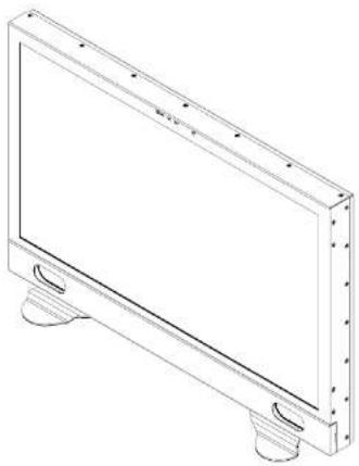
natural_image
Technical line drawing of a rectangular electronic panel with mounting feet (no text or symbols)Operating Instructions
Marshall Electronics
1910 East Maple Ave. EL Sprado, CA 90245
Tel (800) 800-6608 / (310) 333-0606 · Fax: 310-333-0688
www.LCDRacks.com + sales@lcdracks.com
This page intentionally left blank
Maintenance
■ Screen Cleaning
Periodically clean the screen surface using ammonia-free cleaning wipes (Marshall Part No. V-HWP-K). A clean micro-fiber cloth can also be used using only non-abrasive and ammonia-free cleaning agents. Do not use paper towels. Paper towel fibers are coarse and may scratch the surface of the polycarbonate faceplate or leave streaks on the surface. Antistatic and fingerprint resistant cleaning agents are recommended. Do not apply excessive pressure to the screen to avoid damaging the LCD.
■ Faceplate Dusting
Dust the unit with a soft, damp cloth or chamois. Dry or abrasive cloths may cause electrostatic charge on the surface, attracting dust particles. Neutralize static electricity effects by using the recommended cleaning and polishing practice.
Warranty
Marshall Electronics warranties to the first consumer that this V-LCD241MD LCD monitor will, under normal use, be free from defects in workmanship and materials, when received in its original container, for a period of one year from the purchase date. This warranty is extended to the first consumer only, and proof of purchase is necessary to honor the warranty. If there is no proof of purchase provided with a warranty claim, Marshall Electronics reserves the right not to honor the warranty set forth above. Therefore, labor and parts may be charged to the consumer. This warranty does not apply to the product exterior or cosmetics. Misuse, abnormal handling, alterations or modifications in design or construction void this warranty. It is considered normal for a minimal amount of pixels, not to exceed three, to fall on the periphery of the display active viewing area. Marshall Electronics reserves the option to refuse service for display pixel failure if deemed unobtrusive to effective use of the monitor by our technicians. No sales personnel of the seller or any other person is authorized to make any warranties other than those described above, or to extend the duration of any warranties on behalf of Marshall Electronics, beyond the time period described above. Due to constant effort to improve products and product features, specifications may change without notice.
Dimensions
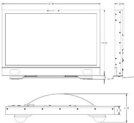
Table of Contents
| Installation and Initial Setup | 4 |
| Front Panel Features | 5 |
| Rear Panel Features | 6 |
| Compatible Input Formats | 7 |
| MAIN MENU AND NAVIGATION | 8 |
| Using the menu buttons | 8 |
| Using the RotoMenu (BRIGHT) knob | 8 |
| Scaling Submenu | 9 |
| Color Submenu | 12 |
| Markers Submenu | 14 |
| Filters Submenu | 16 |
| Audio Submenu | 20 |
| Signal Analysis Submenu | 21 |
| User Settings Submenu | 22 |
| System Submenu | 23 |
| Specifications | 25 |
| Dimensions | 26 |
| Maintenance | 27 |
| Warranty | 27 |
Installation and Initial Setup
■ Unpacking
Carefully unpack the V-LCD241MD monitor and verify that the following items are included:
• V-LCD241MD Monitor (3G Module Optional)
• V-PS12-5V-XLR Power Supply
- Operating Instructions
Inspect the unit for any physical damage that may have occurred during shipping. Should there be any damage, immediately contact Marshall Electronics at (800) 800-6608. If you are not located within the continental United States, call +1 (310) 333-0506.
■ Connections, Power-On and Initial Setup
Plug the power supply into an AC power source (100-240 V @ 50/60 Hz). Attach the Power connector to the back of the monitor. Connect the required cables for video signal input and output. (Power must be applied to the V-LCD241MD for the active loop though output to be activated.) The monitor defaults to 'ON' when power is supplied. Video will automatically be detected and displayed on the screen.
Always install the product in a well ventilated area to ensure proper operating temperatures in the installation environment.
Specifications
■ PANEL
Screen Size 24.0" Diagonal
Display Area (h x v)
Pixels 1920 x RGB x 1080
Brightness 300 cd/m2
Contrast Ratio 3000:1
■ CONNECTORS
HDMI Video Input
1 x HDMI Female Receptacle
HDMI Video Output (Active Loop-Through)
1 x HDMI Female Receptacle
Stereo Headphone Jack
1/8" (3.5mm) Female Jack
Marshall Electronics Module Input (Optional)
Power Input
XLR Connector
ELECTRICAL
Power Consumption
Voltage Requirement
2.0A @ 12VDC [24W]
12 VDC via 4 Pin XLR
MECHANICAL
Weight: 12.10 lbs
Operating Temperature 50°F to 104°F (10°C to
40°C, <50% Humidity
Storage Temperature 32°F to 122°F (0°C to 50°C)
See Dimensions for enclosure measurements
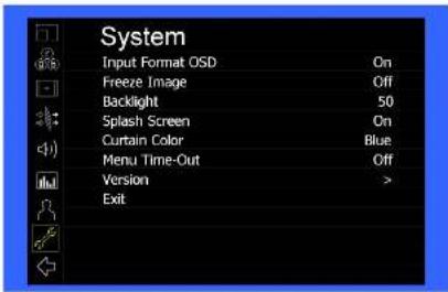
■ Input Format OSD
Use this setting to modify the appearance of the Input Format OSD. Choose between OFF, ON (always on), or 5 Seconds.
■ Freeze Image
Use this function to Freeze the incoming image display.
■ Backlight
Use this function to adjust the Backlight strength of the panel. Values range from 0 (lowest Backlight setting) to 100 (highest Backlight setting). Values increment by 2.
* Raising the backlight value will increase the amount of current used by the monitor, which will reduce battery time.
■ Splash Screen
Use this setting to save the enable (ON) or disable (OFF) the "Marshall Electronics, Inc." splash screen on monitor power up.
■ Curtain Color
Use this setting to select between different Curtain Color settings for the monitor. Choose between Blue, Black or Green.
■ Menu Time-Out
Use this setting to set the Menu Time-Out length. Select between 10-30 seconds (5 second increments) or Off to disable automatic Menu Time-Out.
■ Version
Use this function to view the current Firmware versions of all monitor components.
Front Panel Features
flowchart
graph TD
    A["POWER"] --> B["F1"]
    C["INPUT"] --> D["F2"]
    E["MENU"] --> F["F3"]
    G["SELECT"] --> H["BRIGHT"]
    I["COLOR"] --> J["CONTRAST"]
    K["USER"] --> L["7"]
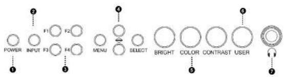
Power Button
Turn the display ON or OFF by pressing the power button. In the ON state, the LED on the power button will dim. In the OFF state, the LED on the button will be at full power.
② Input Select Button
Use the Input select button to switch between the on-board HDMI input or (if available) the module Input.
3 User-Definable Function Buttons
Four user-definable function buttons can be used for direct access to various settings. Functions are assigned using the on-screen menu or by highlighting a function and pressing one of the function buttons. See User Settings Submenu for information on changing Functions.
4 Menu Navigation Buttons
Use the Menu, ↑, ↓, and Select buttons to display and navigate the on-screen menu. See MAIN MENU AND NAVIGATION for details on using the Menu.
⑤ Image Adjustment Knobs
Use the image adjustment knobs to adjust color saturation, brightness and contrast of the image. The status of each image adjustment parameter is shown on the bottom left of the screen, with values ranging from 0 to 100. Pressing a knob once displays the current value. Pressing a knob twice resets the value to the default setting.
# User Control Knob
The USER control knob can be customized to control multiple functions. By default, it controls the volume of the front facing speakers. Change the function of this knob in the MENU. See the User Settings Submenu for more information.
7 Stereo Headphone Jack
The 1/8" Headphone jack on monitor's side takes two channels of embedded HDMI or SDI audio and provides an audio signal. See the Audio Submenu for information on working with audio capabilities.
Rear Panel Features
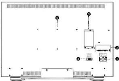
1 Power Connector
Power the unit through this port. Power can be supplied from the included power supply or from a variety of DC sources supplying the appropriate voltage on the listed pins. See the Specifications section for more information.
② HDMI Input and Output
The V-LCD241MD has one HDMI input and one active loop-through output. The HDMI Output is HDCP Compliant and will NOT pass through HDCP protected content. See Compatible Input Formats for details on accepted formats.
Module Slot
Us the Module slot to install the 3GSDI module. Contact Marshall Electronics for more information.
4 Tally Port
For activation of the tally LEDs on the front of the unit.
③ VESA mounting area
Standard VESA mount pattern for customized mounting options.
• Marker Width Toggle through On-Screen Marker widths
Marker Color Toggle through On-Screen Marker colors
Marker Transparency Toggle through Marker Background Transparency settings
- Check Field Toggle through Check Field options
• False Color Enable/disable False Color filter
- Peaking Filter Enable/disable Peaking filter
- Clip Filter Enable/disable the Clip filter
• Clip: Invert Enable/disable the Clip Invert feature
- Clip: Monochrome Enable/disable the Clip Monochrome feature
• Waveform Clip Enable/disable the Clip filter on the Waveform monitor
• Audio Mute Enable/disable the Audio Mute feature
• Audio Channels Toggle through the available Audio Channels
• Signal Analysis Enable/disable the Signal Analysis feature
• Analyzer Layout Toggle through Analyzer Layout setup (audio, video or both)
• Analyzer Position Toggle through Analyzer on-screen locations
• Analyzer Transparency Toggle through Analyzer transparency settings
• Input Format OSD Toggle through Input Format OSD on-screen time
• Freeze Image Enable/disable the Freeze Image feature
- Splash Screen Enable/disable the Splash Screen on monitor startup
• Curtain Color Toggle through different Curtain Colors
• Menu Time Out Toggle through Menu Time-Out settings
• Input Crop Enable/disable the Input Crop feature
All F(function) buttons also act as Function Hot Keys, which makes it easy to assign functions to the available F(function) keys. Simply highlight a function in the menu and press the desired "F" key to assign the function to that key, then press again to confirm the setting. If the function is not available for "F" Hot Key assignment, there will be notification on the screen.
System Submenu
Use the System Submenu Settings to modify general monitor settings.
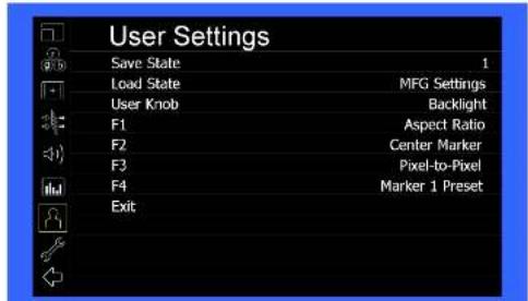
User Settings Submenu
Use the User Settings submenu to customize User Settings and Function buttons on the monitor's keypad for easy access to frequently used features.
■ Save State
Use this setting to save the state of the monitor to 1 of 5 available slots.
- Load State
Use this setting to load a previously configured monitor state. You can also load the Manufacturer Default state (MFG Settings)
■ User Knob
Use this setting to select the function of the USER knob on the monitor's rotary encoder section. Choose between Volume (default), Peaking Threshold (used with the Peaking function) and Backlight.
■ F1, F2, F3, F4
Use this setting to select the functions to be activated by the F1-F4 buttons on the monitor's keypad. Choose between the following options:
• Aspect Ratio Toggle through Aspect Ratio Settings
- Pixel to Pixel Enable/disable Pixel to Pixel
• DSLR Preset Toggle through DSLR Preset settings
• Color Temperature Toggle through Color Temperature presets
- Gamma Toggle through Gamma settings
• Color Space Switch between YCbCr and RGB Color Space (HDMI ONLY)
- Marker Enable Enable/disable On-Screen Markers
• Center Marker Enable/disable the Center Marker
• Marker Select Toggle between two different On-Screen Markers
- Marker Preset Toggle through On-Screen Markers
Compatible Input Formats
MD-3GE
525i/60, 625i/50
720p/25, 29.97, 30, 50, 59.94, 60
1080p/23.98, 23.98sF, 24, 24sF, 25, 29.97, 30
1035/59.94,60
1080/50,59.94,60
3G - Level A
YCbCr, RGB
1080p/60,59.94,50
HDMI Input
480p59.94, 576p50
720p/25, 29.97, 30, 50, 59.94, 60
1080p/23.98, 23.98sF, 24, 24sF, 25, 29.97, 30
1080p/50,59.94,60
1035/59 94 60
1080/50.59.94.60
MAIN MENU AND NAVIGATION
Access and navigate the main menu using the 4 menu buttons or the RotoMenu™ knob:
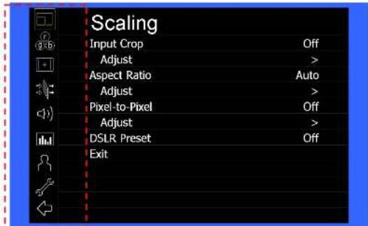
Main Menu
Using the menu buttons
• Press the MENU button to enter the main menu.
• Use the ↑ and ↓ buttons to scroll through the main menu or each submenu.
- Press the SELECT button to enter a submenu or choose a setting.
- Press the MENU button to exit the main menu, or return to the main menu from a submenu.
Using the RotoMenu (BRIGHT) knob
The Marshall Electronics RotoMenu concept has been brought to our line of camera top monitors to make navigating the Main Menu easier than ever. To RotoMenu functionality has been integrated into the BRIGHT knob, so that whenever the Main Menu is up,
• Press the MENU button to enter the main menu.
- Rotate the BRIGHT knob to scroll up or down in the main menu or each submenu.
• Press the BRIGHT knob to enter a submenu or choose a setting.
By default, the menu automatically times out after 15 seconds of being idle.
Signal Analysis Submenu
Use the Video Configuration submenu to select various video settings such as monochrome mode or blue-only mode.
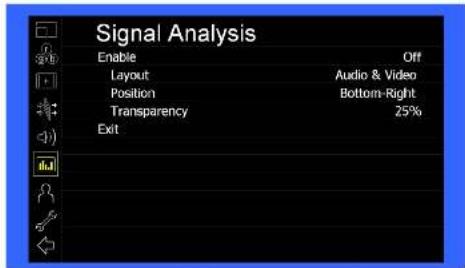
Signsi Analyse Submenu
■ Enable
Use this setting to enable the signal analysis instruments selected in the Layout mode.
Layout
Select which of the signal analysis instruments to display on screen. You can display an Audio Meter (Audio) or a Waveform monitor (VIDEO) or both simultaneously.
■ Position
Select the location of the Signal Analysis instruments on the screen. Choose between Bottom-Right, Bottom-Left, Top-Left and Top-Right.
■ Transparency
Adjust the transparency of the Signal Analysis instruments on the screen. Choose between 0% (completely blocking video in background), 25% (Default), 50% and 75% (show the most amount of video possible).
Audio Submenu
Use the Audio Submenu to enable and adjust the various Audio functions available.
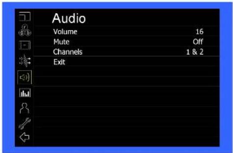
Volume
Use this function adjust the volume of the Headphone jack audio signal.
■ Mute
Use this function to Mute (ON) or Unmute (OFF) the audio output from the Headphone jack.
■ Channels
Use this function to select which stereo audio pair to route to the headphone jack.
HDMI options are stereo pairs 1-8.
MD-3GE options are stereo pairs 1-16.
Scaling Submenu
Use the Scaling submenu to adjust various scaling options and to allow greater control of how your video signal is shown on the display.
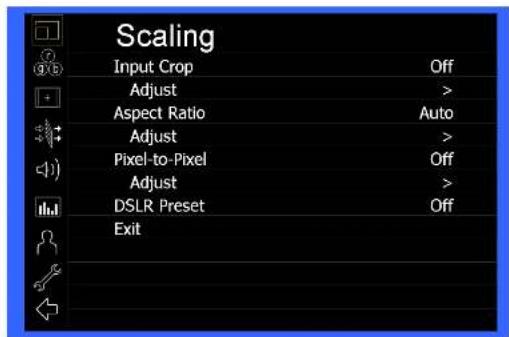
Scaling Submenu
■ Input Crop
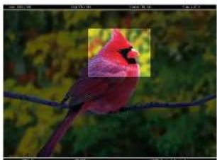
Enable the Input Crop function to select the area of active video that you would like shown on the image display. Select the desired Input by accessing the Adjust option below the main function:
Adjust
Use the BRIGHT knob to move the selection box LEFT and RIGHT.
Use the COLOR knob to move the selection box UP and DOWN.
Use the CONTRAST knob to move the right border LEFT and RIGHT.
Use the USER knob to move the bottom border UP and DOWN.
natural_image
Close-up photo of a red bird perched on a branch with green foliage in the background (no text or symbols visible)When you are satisfied with the position, press the SELECT button or press the BRIGHT knob to confirm your selection.

The new cropped selection will be displayed on the screen. If your Aspect Ratio is set to AUTO, the monitor will select the closest aspect ratio to the dimensions of your customized input.
■ Aspect Ratio
Use this menu option to switch between several aspect ratio settings.
• In 4:3 mode, images are scaled up or down to fill the maximum 4:3 portion of the screen.
• In 16:9 mode, images are scaled to fill the entire 16:9 screen.
• In Full Screen, images are scaled to fill the entire screen.
• In Custom mode, images scaling is adjusted to your selection in the Adjust portion of the menu;
Adjust
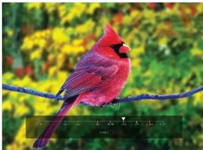
Use any of the rotary knobs to select your desired aspect ratio. Some of the more common aspect ratio settings are shown on the Aspect Ratio selection widget. As you move along the scale, your current aspect ratio will be displayed below the widget.

Aspect Ratio selection widget
In the image above, the Lower Threshold has been set to 20 IRE (Red). This means that any part of the image UNDER 20 IRE will be "colored" in RED. Also, the Upper Threshold has been set to 90 IRE (Yellow). This means that any part of the image OVER 90 IRE will be "colored" in YELLOW.
■ Invert
The Clip function can also be inverted to filter the area between the Upper and Lower Threshold. The color selected for the Lower Threshold acts as the color for all inverted Clip data.
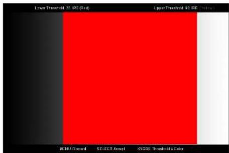
In the image above, the Lower Threshold is set to 20 IRE and the Upper Threshold is set to 90 IRE. The Clip Invert will filter all data in between 20 IRE and 90 IRE and color it RED.
■ Monochrome
Enabling Monochrome in the Clip filter will convert all video to monochrome first, and then apply the Clip filter. This helps visually filtered data stand out from regular color video.
■ Apply To Waveform
Enabling Monochrome in the Clip filter will convert all video to monochrome first, and then apply the Clip filter. This helps visually filtered data stand out from regular color video.
■ Peaking (Focus assist)
The Peaking Filter is used to aid the camera operator in obtaining the sharpest possible picture.
You can turn the Peaking filter ON and adjust the Threshold and Color by accessing the Adjust function. Use the BRIGHT knob to adjust the Threshold. Adjusting the Threshold to a higher value forces the Peaking algorithm to react quicker to objects that are in focus. Use COLOR knob to adjust the Color. Your choice is arc Red (default), Yellow, Pink, Green and Blue,
Clip
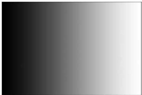
The Clip function is used to visually filter data on the screen that is under a Lower Threshold or over an Upper Threshold. Data on either side of the filters can be filtered with a custom color.
natural_image
Gradient grayscale image transitioning from black to white (no text or symbols)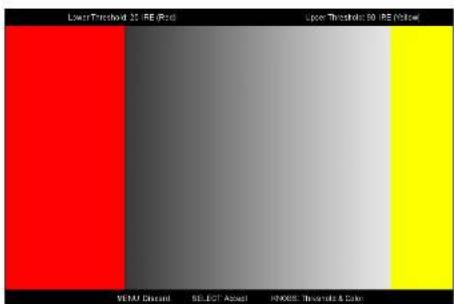
The Lower Threshold numerical value and color can be adjusted using the BRIGHT and COLOR knob, respectively. The Upper Threshold can be adjusted using the CONTRAST and USER knob, respectively.
natural_image
Red California Red Clifton perched on a branch with green foliage background (no text or symbols)Custom Aspect Ratio selection
■ Pixel-to-Pixel
Use this setting to enable Pixel-to-Pixel mode.
This mode bypasses the monitor's internal scaling function and displays images in their native resolution and aspect ratio, with a one-to-one mapping of incoming image pixels to screen pixels:
- For incoming formats smaller than the native resolution of the screen (or selected aspect ratio), the image will be displayed in the center of the screen using only the necessary LCD pixels. For example, 720p images will occupy exactly 1280x720 pixels in the center of the screen. The surrounding screen area will be black.
■ DSLR Preset
Use the DSLR Preset option to reduce the visibility of on screen indicators shown with popular DSLR cameras. The available options are:
■ NK 16:9
• NK 3:2
CN 16:9
• CN 3:2
Color Submenu
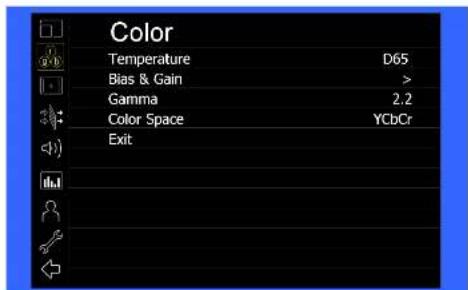
IMD Configuration Submenu
■ Temperature
Use this setting to choose one of three color temperature presets:
• DSS (5500K)
• D65 (6500K)
• D93 (9300K)
Custom (Adjustable Color Bias and Gain)
• Linear (No processing is applied to the panel)
■ Bias & Gain
Select this submenu to fine-tune the monitor's color balance (R, G, B). This should only be done by someone experienced with video engineering, as this will alter the overall color shading of the screen. The purpose is to allow color matching to other types of monitors and/or displays. Note: The Color Temperature preset will automatically switch to Custom when Color Bias settings are adjusted. It is normal for color bias adjustments to be very subtle.
When selecting the RGB Bias and Gain submenu, bias adjustment indicators will appear at the top of the screen, and gain adjustment indicators will appear at the bottom of the screen:
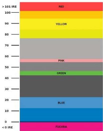
This monitor has a false color filter to aid in the setting of camera exposure. As the camera iris is adjusted, elements of the image will change color based on the luminance or brightness values. This enables proper exposure to be achieved without the use of costly, complicated external equipment. To best utilize this feature, you must understand the color chart below and have a basic understanding of camera exposure. Normally, when shooting subjects like people, it is common practice to set exposure of faces to the equivalent of approximately 55 IRE. The false color filter will show this area as the color PINK on the monitor. Therefore, as you increase exposure (open the IRIS), your subject will change color as indicated on the chart: PINK, then GREY, then a few shades of YELLOW. Over exposed subjects (above 101 IRE) on the monitor will be shown as RED. In addition, underexposed subjects will show as DEEP-BLUT to DARK-BLUT, with clipped blacks indicated with a FUCHSIA-like color. Lastly, the color GREEN is used to indicate elements of the image that are approximately 45 IRE. This represents a 'neutral' or 'mid-level' exposure commonly used for objects (not people).
bar_stacked
| Category | Value | |---|---| | RED | 101 | | 100 | 101 | | YELLOW | 90 | | 80 | 80 | | 70 | 70 | | 60 | 60 | | 50 | 50 | | 40 | 40 | | 30 | 30 | | 20 | 20 | | BLUE | 10 | | 10 | 0 | | < 0 IRE | 0 | FUCHSIA | 0 |False Color Key
Filters Submenu
Use the Filters Submenu to enable various modes.
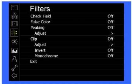
- Check Field
Use the check field modes for monitor calibration or to analyze individual color components of an image. In Monochrome mode, all color is disabled and only a grayscale image is shown. In Blue, Green, and Red check field modes, only the selected color will be shown.
Use the following procedure when calibrating the monitor to SMPTE color bars with the following procedure:
- Allow the monitor to warm up for at least 5-10 minutes.
- Display SMPTE split-field color bars on the monitor using an external source.
- Enable Monochrome mode.
- Locate the plugc pattern (super black, black, and gray bars) at the lower-right corner of the screen. Adjust the Brightness knob until there is no visible difference between the super black and black bars, but the gray bar is still visible.
- Adjust the Contrast knob until an even grayscale appears along the top bars.
- Disable Monochrome mode.
- Enable Blue Check Field mode and adjust the Color knob so that the outermost bars (white and blue) appear to match in brightness.
- Disable Blue Check Field mode.
False Color
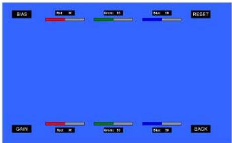
Use the ▲ and ▼ buttons to select each individual bias or gain control. Highlighting the BIAS or GAIN icons enables a group change of the Red, Green and Blue color components, respectively. Alternatively, you can use the BRIGHT knob to scroll through the different color components and settings.
After selecting the color component to adjust, use the ▲ and ▼ buttons to increase or decrease the value.
■ Gamma
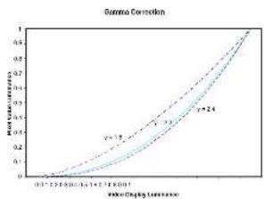
Use the Gamma setting to adjust the value of the gamma applied to incoming video signals. The default gamma value is 2.2. Gamma correction represents the relationship between the pixel levels from your incoming video and the luminance of your monitor. The lowest gamma level available, 1.5, will cause the image to appear brighter. The highest gamma level available, 2.4, will cause the image to appear darker. The chart below shows this on a scale.
line
| Index Display Temperature | Total Correlation (γ=1.5) | Total Correlation (γ=2.4) | Total Correlation (γ=3.5) | | ------------------------- | -------------------------- | -------------------------- | -------------------------- | | 0.0 | 0.0 | 0.0 | 0.0 | | 0.2 | 0.1 | 0.1 | 0.1 | | 0.4 | 0.2 | 0.2 | 0.2 | | 0.6 | 0.3 | 0.3 | 0.3 | | 0.8 | 0.4 | 0.4 | 0.4 | | 1.0 | 0.5 | 0.5 | 0.5 |■ Color Space
Use this setting to automatically detect (Auto) or select the color space (RGB or YCrCb) of incoming HDMI video. This should match the color space of the video output settings on your playback device.
Markers Submenu
Use the Markers submenu to select various types of markers and settings in 4:3, 16:9, or Full Screen mode.
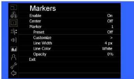
Markers Submera
■ Marker Enable
The Marker Enable setting turns 16:9 or 4:3 screen markers On or Off. By default, this setting is On.
■ Center Marker
Use this setting to display a center marker on the screen.
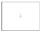
Center Marker
■ Marker Selection
Use this setting to adjust and view the settings of 1 of 2 available markers.
■ Presets
Use this setting to superimpose one of 13 markers on the screen or 1 custom setting. This setting is disabled when the Pixel-to-Pixel mode is enabled.
- Off (No Marker)
• 4:3 Aspect Ratio
• 13:9 Aspect Ratio
• 14:9 Aspect Ratio
• 16:9 Aspect Ratio
• 1.85:1 Aspect Ratio
• 2.35:1 Aspect Ratio
• 2.39-1 Aspect Ratio
• 95% Safe Area
- 92% Safe Area
- 95% Safe Area
- 90% Safe Area
- 50% Sale Area
- 88% Sale Area
- 85% Safe Area
- 80% Safe Area
- Custom
- Customize
Use this setting to customize the screen markers by using the BRIGHT, COLOR, CONTRAST and USER knobs. These control the LEFT, RIGHT, TOP and BOTTOM edges, respectively.

natural_image
Red bird perched on a branch with green foliage background (no text or symbols visible)Each Marker (1 or 2) can be fully customized in this fashion.
■ Line Width
Use this setting to choose the width of the marker lines, from 1 px (thinnest) to 10 px (widest).
■ Line Color
Use this setting to select a custom color for the Screen Markers. You can choose between White (default), Yellow, Red, Green and Blue.
■ Transparency (Opacity)
Use this setting to select the transparency of the marker background. Choose between 0% (black), 25%, 50%, 75% and 100% (see through) transparency.
- Marshall Electronics
- Maintenance
- ■ Screen Cleaning
- ■ Faceplate Dusting
- Warranty
- Installation and Initial Setup
- ■ Unpacking
- ■ Connections, Power-On and Initial Setup
- Specifications
- ■ PANEL
- ■ CONNECTORS
- ELECTRICAL
- MECHANICAL
- Front Panel Features
- Power Connector
- ② HDMI Input and Output
- Module Slot
- Tally Port
- ③ VESA mounting area
- System Submenu
- User Settings Submenu
- Compatible Input Formats
- MD-3GE
- MAIN MENU AND NAVIGATION
- Using the menu buttons
- Using the RotoMenu (BRIGHT) knob
- Signal Analysis Submenu
- ■ Enable
- Layout
- ■ Position
- ■ Transparency
- Audio Submenu
- Scaling Submenu
- ■ Aspect Ratio
- ■ Invert
- ■ Monochrome
- ■ Apply To Waveform
- ■ Peaking (Focus assist)
- Clip
- ■ Pixel-to-Pixel
- ■ DSLR Preset
- Color Submenu
- ■ Temperature
- ■ Bias & Gain
- Filters Submenu
- - Check Field
- False Color
- ■ Gamma
- ■ Color Space
- Markers Submenu
- ■ Marker Enable
- ■ Center Marker
- ■ Marker Selection
- ■ Presets
- - Customize
- ■ Line Width
- ■ Line Color
- ■ Transparency (Opacity)
Brand : Marshall Electronics
Model : V-LCD241MD
Category : Pregnant