DG832 - Generator Rigol - Free user manual and instructions
Find the device manual for free DG832 Rigol in PDF.


| Product Type | Function / Arbitrary Waveform Generator |
| Number of Channels | 2 |
| Maximum Frequency (Sine) | 30 MHz |
| Waveforms | Sine, Square, Ramp, Pulse, Noise, DC, Arbitrary |
| Sample Rate | 200 MSa/s |
| Vertical Resolution | 14 bits |
| Memory Depth | 16 kpts per channel |
| Amplitude Range | 1 mVpp to 10 Vpp (into 50 Ω) |
| Frequency Resolution | 1 μHz |
| Modulation Types | AM, FM, PM, FSK, ASK, PWM, DSB-AM |
| Display | 4.3-inch TFT LCD, 480 x 272 pixels |
| Dimensions (W x H x D) | 260 mm x 107 mm x 295 mm |
| Weight | 3.5 kg |
| Power Supply | AC 100-240 V, 50/60 Hz |
| Interfaces | USB (Host & Device), LAN (10/100), Option GPIB |
| Cleaning | Wipe with a soft dry cloth; do not use solvents. |
| Maintenance | Replaceable fuse (T2A/250V); no user-serviceable parts inside. |
| Safety | Overvoltage protection, safety earth; meet EN 61010-1. |
| Warranty | 3 years standard, optional extended warranty. |
| Accessories Included | Power cord, USB cable, BNC cables (2), quick start guide. |
Frequently Asked Questions - DG832 Rigol
User questions about DG832 Rigol
0 question about this device. Answer the ones you know or ask your own.
Ask a new question about this device
Download the instructions for your Generator in PDF format for free! Find your manual DG832 - Rigol and take your electronic device back in hand. On this page are published all the documents necessary for the use of your device. DG832 by Rigol.
USER MANUAL DG832 Rigol
Function/ Arbitrary Waveform Generator
Jul. 2018
RIGOL (SUZHOU) TECHNOLOGIES INC.
Guaranty and Declaration
Copyright
© 2018 RIGOL (SUZHOU) TECHNOLOGIES INC. All Rights Reserved.
Trademark Information
RIGOL is a registered trademark of RIGOL (SUZHOU) TECHNOLOGIES INC.
Publication Number
PGB11100-1110
Software Version
00.00.01
Software upgrade might change or add product features. Please acquire the latest version of the manual from RIGOL website or contact RIGOL to upgrade the software.
Notices
● RIGOL products are covered by P.R.C. and foreign patents, issued and pending.
- RIGOL reserves the right to modify or change parts of or all the specifications and pricing policies at the company's sole decision.
● Information in this publication replaces all previously released materials.
● Information in this publication is subject to change without notice.
- RIGOL shall not be liable for either incidental or consequential losses in connection with the furnishing, use, or performance of this manual, as well as any information contained.
- Any part of this document is forbidden to be copied, photocopied, or rearranged without prior written approval of RIGOL.
Product Certification
RIGOL guarantees that this product conforms to the national and industrial standards in China as well as the ISO9001:2015 standard and the ISO14001:2015 standard. Other international standard conformance certifications are in progress.
Contact Us
If you have any problem or requirement when using our products or this manual, please contact RIGOL.
E-mail: service@rigol.com
Website: www.rigol.com
Document Overview
This manual introduces how to program the signal generator over the remote interfaces in details.
Main Topics in this Manual:
Chapter 1 Programming Overview
This chapter introduces how to build the remote communication between the signal generator and the PC; how to control the signal generator remotely. It also introduces the syntax, symbols, parameter types, and abbreviation rules of the SCPI commands.
Chapter 2 Command System
This chapter introduces the syntax, function, parameters, and usages of each DG800 command in A-Z order.
Chapter 3 Application Instances
This chapter provides the application examples of the main functions of the signal generator. In the examples, a series of commands are combined to realize the basic functions of the signal generator.
Chapter 4 Programming Examples
This chapter illustrates how to control DG800 by programming in the development environments such as Visual C++, Visual Basic, and LabVIEW.
Chapter 5 Appendix
This chapter provides the command list and the factory settings.
Tip
For the latest version of this manual, download it from the official website of RIGOL (www.rigol.com).
Format Conventions in this Manual:
1. Keys:
The keys on the front panel are usually denoted by the format of "Key Name (Bold) + Text Box". For example, Utility denotes the Utility key.
2. Menu Labels:
The menu labels are usually denoted by the format of "Menu Word (Bold) + Character Shading". For example, System Setting.
3. Operation Procedures:
"→" represents the next step of operation. For example, Utility → System Setting denotes that first press Utility on the front panel, and then tap the System Setting menu label.
Content Conventions in this Manual:
DG800 series function/arbitrary waveform generator includes the following models: Unless otherwise specified, this manual takes DG832 as an example to introduce each command of the DG800 series.
| Model | No. of Channels | Max. Output Frequency |
| DG812 | 2 | 10 MHz |
| DG822 | 2 | 25 MHz |
| DG832 | 2 | 35 MHz |
| DG811 | 1 | 10 MHz |
| DG821 | 1 | 25 MHz |
| DG831 | 1 | 35 MHz |
Contents
Guaranty and Declaration.... I
Document Overview ......II
Chapter 1 Programming Overview.... 1-1
Build Remote Communication 1-2
Remote Control Method....1-4
SCPI Command Overview 1-4
Syntax 1-4
Symbol Description....1-5
Parameter Type 1-5
Command Abbreviation....1-6
Chapter 2 Command System.... 2-1
:COUNter Commands 2-2
:COUpling Commands 2-8
:DISPLAY Commands....2-19
:HCOPy Commands....2-21
IEEE488.2 Common Commands 2-22
:LICENSE Commands 2-29
:MEMory Commands 2-31
:MMEMory Commands....2-34
:OUTPUT Commands....2-43
:ROSCillator Commands....2-48
:SOURce Commands 2-50
:SOURce:APPLY 2-51
:SOURce:BURSt....2-58
:SOURce:FREQuency 2-66
:SOURce:FUNCTION 2-73
:SOURce:HARMonic 2-89
:SOURce:MARKer 2-93
:SOURce[:MOD]:AM 2-94
:SOURce[:MOD]:ASKey 2-99
:SOURce[:MOD]:FM....2-102
:SOURce[:MOD]:FSKey 2-106
:SOURce[:MOD]:PM....2-109
:SOURce[:MOD]:PSKey 2-112
:SOURce[:MOD]:PWM....2-116
:SOURce:MOD....2-120
:SOURce:PERiod....2-122
:SOURce:PHASE 2-123
:SOURce:PULSe....2-124
:SOURce:SUM 2-126
:SOURce:SWEep....2-129
:SOURce:TRACE 2-136
:SOURce:TRACK....2-137
:SOURce:VOLTage 2-137
:SYSTem Commands 2-142
:TRIGger Commands....2-156
Chapter 3 Application Instances.... 3-1
To Output Basic Waveforms 3-2
To Output the Arbitrary Waveform....3-2
To Output Harmonic....3-3
To Output AM Modulated Waveform 3-3
To Output FSK Modulated Waveform 3-4
To Output Sweep Waveform....3-4
To Output Burst Waveform 3-5
To Use the Frequency Counter 3-5
Chapter 4 Programming Examples ....4-1
Programming Preparations 4-2
Excel Programming Examples 4-3
Matlab Programming Example 4-6
LabVIEW Programming Example....4-8
Visual Basic Programming Example 4-15
Visual C++ Programming Example....4-18
Chapter 5 Appendix ....5-1
Appendix A: Factory Setting 5-1
Appendix B: Warranty 5-5
Chapter 1 Programming Overview
This chapter introduces how to build the remote communication between the signal generator and the PC; how to control the signal generator remotely. It also introduces the syntax, symbols, parameter types, and abbreviation rules of the SCPI commands.
Contents in this chapter:
◆ Build Remote Communication
◆ Remote Control Method
◆ SCPI Command Overview
Build Remote Communication
You can build the remote communication between DG800 and the PC via the USB (USB DEVICE), LAN (extended from the USB HOST interface by using the USB-LAN interface converter) or GPIB interface (extended from the USB HOST interface by using the USB-GPIB interface converter).
Operation Procedures:
1. Install Ultra Sigma (PC) software
Download the Ultra Sigma common PC software from www.rigol.com and install it according to the instructions.
2. Connect the analyzer to the PC and configure the interface parameters for the instrument DG800 supports the USB, LAN (extended from the USB HOST interface by using the USB-LAN interface converter), and GPIB (extended from the USB HOST interface by using the USB-GPIB interface converter) communication interfaces, as shown in the figure below.
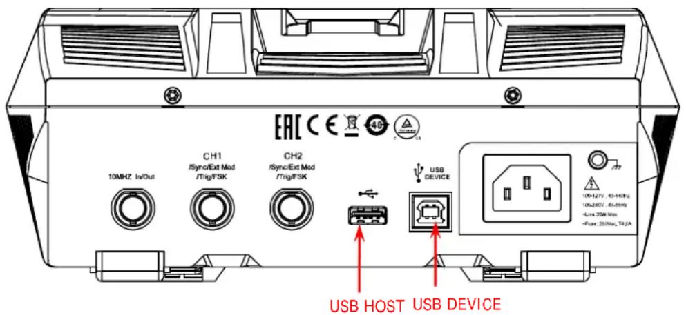
Figure 1-1 DG800 Communication Interface
1) Use the USB interface: connect the USB DEVICE interface on the rear panel of DG800 and the USB HOST interface of the PC by using a USB cable. The "Found New Hardware Wizard" dialog box will be displayed and please install the "USB Test and Measurement Device (IVI)" according to the instructions (refer to "Remote Control via USB" in Chapter 3 "Remote Control" in DG800 User's Guide).
2) Use the LAN interface:
● Make sure that your PC has been accessed to the local area network.
- Check whether the local area network where your PC resides supports DHCP or auto IP mode. If not, you need to acquire the network interface parameters available, such as the IP address, subnet mask, default gateway, and DNS.
- Extend a LAN interface by connecting the USB HOST interface on the rear panel of DG800 by using the USB-LAN interface converter.
- Use the network cable to have DG800 get access to the local area network.
- Press Utility → Interface → LAN to configure the IP address, subnet mask, default gateway, and DNS.
3) Use the GPIB interface:
- Extend a GPIB interface by connecting the USB HOST interface on the rear panel of DG800 by using the USB-GPIB interface converter.
● Use the GPIB cable to connect the instrument to your PC. - Press Utility → Interface → GPIB to set the GPIB address of the instrument.
3. Check whether the connection is successful
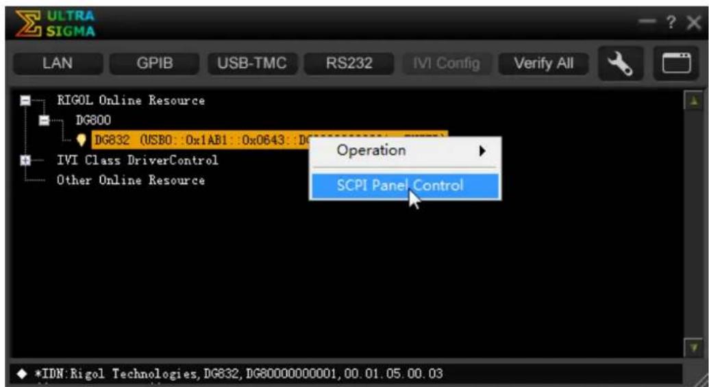
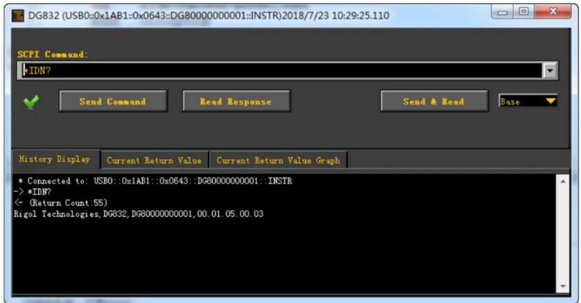
Run Ultra Sigma, and then search for the resources and right-click the resource name. Select "SCPI Panel Control" to open the SCPI command control panel. Input a correct command in the pop-up SCPI
control panel and click Send Command and Read Response in sequence or directly click
Send & Read to check whether the connection is successful, as shown in the figure below (the USB interface is taken as an example).
Remote Control Method
1. User-defined programming
You can use the SCPI (Standard Commands for Programmable Instruments) commands listed in Chapter 2 "Command System" of this manual to program and control the instrument in various development environments (e.g. Visual C++, Visual Basic, and LabVIEW). For details, refer to descriptions in Chapter 4 "Programming Examples".
2. Send SCPI commands via the PC software
You can use the PC software to send commands to control the signal generator remotely. RIGOL Ultra Sigma is recommended. You can download the software from RIGOL official website (www.rigol.com).
SCPI Command Overview
SCPI (Standard Commands for Programmable Instruments) is a standardized instrument programming language that is built upon the existing standard IEEE 488.1 and IEEE 488.2 and conforms to various standards, such as the floating point operation rule in IEEE 754 standard, ISO 646 7-bit coded character set for information interchange (equivalent to ASCII programming). This chapter introduces the syntax, symbols, parameters, and abbreviation rules of the SCPI commands.
Syntax
The SCPI commands provide a hierarchical tree structure, and consist of multiple subsystems. Each command subsystem consists of one root keyword and one or more sub-keywords. The command line usually starts with a colon; the keywords are separated by colons, and following the keywords are the parameter settings available. The command ending with a question mark indicates querying a certain function. The keywords of the command and the first parameter is separated by a space.
For example,
:SYSTem:COMMunicate:LAN:IPADdress
:SYSTem:COMMunicate:LAN:IPADdress?
SYSTem is the root keyword of the command. COMMunicate, LAN, and IPADdress are the second-level, third-level, and forth-level keywords respectively. The command string starts with ":" which is also used to separate the multiple-level keywords.
command :SYSTem:COMMunicate:LAN:IPADdress and the parameter
In some commands with parameters, "," is often used to separate multiple parameters. For example, :DISPLAY:TEXT[:SET]
Symbol Description
The following four symbols are not part of the SCPI command, and they are not sent with the commands, but taken as delimiters to better describe the parameters in the command.
1. Braces { }
The contents enclosed in the braces can contain multiple parameter options; and the vertical bar is used to separate multiple parameter options. When sending the command, you must select one of the parameters. For example, :COUPLing[
2. Vertical Bar |
The vertical bar is used to separate multiple parameters. When using the command, you must select one of the parameters. For example, :COUPLing[
3. Square Brackets []
The contents (command keywords or parameters) in the square brackets can be omitted. If the parameter is omitted, the instrument will set the parameter to its default. For example, for the :COUNter:STATIstics[:STATE]? command, send any of the following two commands can achieve the same effect.
:COUNTER:STATI stics?
:COUNTER:STATIstics:STATE?
4. Triangle Brackets <>
The parameter enclosed in the angle brackets must be replaced by an effective value. For example, sending the :COUNter:LEVEL
Parameter Type
The command parameters introduced in this manual include 5 types: Bool, Integer, Real, Discrete, and ASCII String.
1. Bool
The parameter can be set to "ON (1)" or "OFF (0)". For example, :COUNTER:HF {ON|1|OFF|0}.
2. Integer
Unless otherwise specified, the parameter can be any integer within the effective value range. Note: Do not set the parameter to a decimal, otherwise, errors will occur. For example, in the :DISPLAY:BRIGHTness
3. Real
Unless otherwise noted, the parameter can be any number within the effective value range. For example, the range of
4. Discrete
The parameters can only be the specified numerical values or characters. For example, in the :COUpling[
5. ASCII String
The parameter can be the combinations of ASCII characters. For example, in the :MMEMory:LOAD:STATE
Besides, you can replace the parameters in many commands with MI Nimum or MAXimum to set the parameters to their minimum or maximum value.
For example, MINimum and MAXimum in the :DISPLAY:BRIGHTness {
Command Abbreviation
The letters in the commands are case-insensitive. The commands can be input all in uppercase letters or in lowercase letters. For abbreviations, you must enter all the uppercase letters that exist in the command syntax. For example, the :COUNTER:COUPLing? command can be abbreviated as :COUN:COUP?.
Chapter 2 Command System
This chapter introduces the syntax, function, parameters, and usages of each DG800 command in A-Z order.
Contents in this chapter:
◆ :COUNTER Commands
◆ :COUPIING Commands
◆ :DISPLAY Commands
◆ :HCOPy Commands
IEEE488.2 Common Commands
◆ :LICense Commands
◆ :MEMory Commands
◆ :MMEMory Commands
◆ :OUTPut Commands
◆ :ROSCillator Commands
◆ :SOURce Commands
◆ :SYSTem Commands
◆ :TRIGger Commands
Remarks: In this command system, setting commands relating to the frequency and amplitude parameters can be sent with units. The units available and the default unit of each parameter are as shown in the table below.
| Parameter Type | Units Available | Default Unit |
| Frequency | MHz/kHz/Hz/uHz | Hz |
| Sample Rate | MSa/s, kSa/s, Sa/s, uSa/s | Sa/s |
| Amplitude Vpp/mVpp/Vrms/mVrms/dBm | Vpp/Vrms/dBm (Relates to the current amplitude unit to be set.) | |
| Offset V | _dc /mV _dc | V_dc |
| High Level/Low Level | V/mV | V |
| Time | Ms/ks/s/ms/us/ns | s |
| Phase | ° | ° |
| Duty Cycle/Modulation Depth/Brightness/ | % | % |
| Impedance | Ω | Ω |
Note:
- In this manual, the range of the parameter in the command takes DG832 as an example.
- As all the commands are case-insensitive, for DG800, MHZ (mhz) and MSA/S (msa/s) are interpreted as megahertz and mega points per second respectively; whereas MVPP (mvpp), MVRMS (mvrms), MVDC (mvdc), MV (mv), and MS (ms) are interpreted as millivolt (peak-peak value), millivolt (effective value), millivolt (DC), millivolt, and millisecond respectively.
- When the output impedance is HighZ, the amplitude unit dBm is invalid.
:COUNTER Commands
The :COUNTER commands are used to enable or disable the frequency counter; set the related information of the frequency counter.
Command List ^[1] :
◆ :COUNTER:AUTO
◆ :COUNTER:COUPLing
◆ :COUNTER:GATEme
◆ :COUNter:HF
◆ :COUNTER:LEVEI
◆ :COUNTER:MEASure?
◆ :COUNTER:SENSitive
◆ :COUNTER[:STATE]
◆ :COUNTER:STATI stics:CLEAr
◆ :COUNTER:STATIstics[:STATE]
Note ^[1] : In the "Command List" in this manual, the parameters in the setting commands and the query commands are not included and you can refer to the complete introductions of the commands in the text according to the keywords.
:COUNTER:AUTO
Syntax
:COUNTER:AUTO
Description
The instrument will select a proper gate time automatically according to the characteristics of the signal under test after sending this command.
Remarks
You can also send the :COUNTER:GATEme command to set the desired gate time.
:COUNTER:COUPLING
Syntax
:COUNTER:COUPLING {AC|DC}
:COUNTER:COUPLING?
Description
Sets the coupling mode of the input signal to AC or DC.
Queries the coupling mode of the input signal.
Parameter
| Name | Type | Range | Default |
| {AC|DC} | Discrete | AC|DC | AC |
Return Format
The query returns AC or DC.
Example
:COUN:COUP DC /* Sets the coupling mode of the input signal to DC.*/
:COUN:COUP? /*Queries the coupling mode of the input signal and the query returns DC.*/
:COUNTER:GATEme
Syntax
:COUNter:GATEmime {USER1|USER2|USER3|USER4|USER5|USER6}
:COUNter:GATEme?
Description
Selects the gate time of the measurement system.
Queries the gate time of the measurement system.
Parameter
| Name | Type | Range | Default |
| { USER1|USER2|USER3|USER4|USER5|USER6} | Discrete | { USER1|USER2|USER3|USER4|USER5|USER6} | USER1 |
Remarks
● The gate time represented by USER1 through USER6 are as shown in the table below.
| USER1 | USER2 | USER3 | USER4 | USER5 | USER6 |
| 1.048ms | 8.389 ms | 134.218 ms | 1.074 s | 8.590 s | >8.590 s |
- For low-frequency signals (for example, the frequency is lower than 5 Hz), you are recommended to set the gate time to USER6.
- Send the :COUNTER:AUTO command and the instrument will select a proper gate time automatically
according to the characteristics of the signal under test. During this process, "AUTO" is displayed in the gate time area in the frequency counter interface. The gate time currently selected by the instrument will be displayed in the gate time area in the frequency counter interface after the instrument selects a proper gate time.
Return Format
If you have currently selected a gate time, the query returns USER1, USER2, USER3, USER4, USER5, or USER6 that corresponds to the specified gate time. If you send the :COUNTER:AUTO command to enable the instrument to select a proper gate time automatically, then during this process, the query returns "AUTO"; and returns USER1, USER2, USER3, USER4, USER5, or USER6 after a proper gate time is selected by the instrument.
Example
:COUN:GATE USER2 /* Sets the gate time of the measurement system to USER2 (10.48 ms).*/ :COUN:GATE? /* Queries the gate time of the measurement system and the query returns USER2.*/
:COUNTER:HF
Syntax
:COUNTER:HF {ON|1|OFF|0}
:COUNTER:HF?
Description
Enables or disables the high frequency rejection function of the frequency counter. Queries the on/off status of the high frequency rejection function of the frequency counter.
Parameter
| Name | Type | Range | Default |
| {ON|1|OFF|0} | Bool | ON|1|OFF|0 | OFF |
Remarks
Enable the high frequency rejection when low-frequency signal with less than 150 kHz frequency is measured to filter out the high-frequency noise interference and improve the measurement accuracy. Disable the high frequency rejection when high-frequency signal with greater than 150 kHz frequency is measured. At this time, the maximum input frequency can be 240 MHz.
Return Format
The query returns ON or OFF.
Example
:COUN:HF ON /*Enables the high frequency rejection function of the frequency counter.*/ :COUN:HF? /*Queries the on/off status of the high frequency rejection function of the frequency counter and the query returns ON.*/
:COUNTER:LEVEI
Syntax
:COUNTER:LEVEL {
:COUNTER:LEVEL? [MINimum|MAXimum]
Description
Sets the trigger level of the frequency counter. Queries the trigger level of the frequency counter.
Parameter
| Name | Type | Range | Default |
| Real | -2.5 V to 2.5 V | 0V |
Remarks
● The frequency counter starts measuring when the input signal reaches the specified trigger level.
● The minimum resolution is 6 mV.
Return Format
The query returns the trigger level in scientific notation. The returned value contains 7 effective digits, for example, 1.500000E+00 (the trigger level is 1.5 V).
Example
:COUN:LEVE 1.5 /* Sets the trigger level of the frequency counter to 1.5 V.*/ :COUN:LEVE? /* Queries the trigger level of the frequency counter and the query returns 1.500000E+00.*/
:COUNTER:MEASure?
Syntax
:COUNTER:MEASure?
Description
Queries the measurement results of the frequency counter.
Remarks
When the frequency counter is in the "RUN" or "SINGLE" state, send this command to query the measurement values. When the frequency counter is in the "STOP" state, send this command to query the measurement values of the last measurement.
Return Format
The query returns a string consisting of 5 parts (representing the frequency, period, duty cycle, positive pulse width, and negative pulse width respectively), separated by commas. Each part is expressed in scientific notation and contains 10 effective digits, for example, 2.000000000E+03,5.000000000E-04,4.760800000E+01,2.380415000E-04, 2.619585000E-04 (representing the measurement result: 2 kHz frequency, 500 us period, 47.608% duty cycle, 238.0415 us positive pulse width, and 261.9585 us negative pulse width). When the frequency counter function is disabled, the query returns 0.000000000E+00,0.000000000E+00, 0.000000000E+00, 0.000000000E+00, 0.000000000E+00, 0.000000000E+00, 0.000000000E+
Example
:COUN:MEAS? /*Queries the measurement results of the frequency counter and the query returns 2.000000000E+03,5.000000000E-04, 4.760800000E+01,2.380415000E-04,2.619585000E-04.*/
:COUNTER:SENSitive
Syntax
:COUNter:SENSitive {LOW|HIGH} :COUNter:SENSitive? [LOW|HIGH]
Description
Sets the trigger sensitivity of the frequency counter. Queries the trigger sensitivity of the frequency counter.
Parameter
| Name | Type | Range | Default |
| {LOW|HIGh} | Real | LOW|HIGh | LOW |
Remarks
A higher sensitivity is recommended for the signal with a small amplitude; a low sensitivity is recommended for a low-frequency signal with a large amplitude or a signal with a slow rising edge to ensure the accuracy of the measurement result.
Return Format
The query returns LOW or HIG.
Example
:COUN:SENS LOW /* Sets the trigger sensitivity of the frequency counter to LOW.*/
:COUN:SENS? /*Queries the trigger sensitivity of the frequency counter and the query returns LOW.*/
:COUNTER[:STATe]
Syntax
:COUNTER[:STATe] {ON|1|OFF|0|RUN|STOP|SINGLE}
:COUNTER[:STATE]?
Description
Sets the status of the frequency counter.
Queries the status of the frequency counter.
Parameter
| Name | Type | Range | Default |
| {ON|1|OFF|0|RUN|STOP|SINGLE} | Discrete | ON|1|OFF|0|RUN|STOP|SINGLE | OFF |
Remarks
- "ON" and "1" denote enabling the frequency counter function; "OFF" and "0" denote disabling the frequency counter function; "RUN", "STOP", and "SINGLE" denote setting the running status of the frequency counter to "run", "stop", and "single" respectively.
- The command for setting the operating status (the parameter is RUN, STOP, or SINGLE) is only valid when the frequency counter function is enabled.
- When the frequency counter function is enabled, the sync output of CH2 will be disabled.
- In the "RUN" status, the frequency counter measures the input signal continuously according to the current configuration. In the "SINGLE" status, the frequency counter executes a measurement, then enters the "STOP" status, and then stops measurement. In the "STOP" status, the frequency counter stops measuring.
- When the frequency counter is enabled, the default operating status is "RUN", and the instrument measures the input signal continuously according to the current configuration. At this point, if you send the :COUNter:STATe SINGLE command, the frequency counter enters the "Single" status, finishes the current measurement, and then stops; if you send the :COUNter:STATe STOP command, the frequency counter enters the "STOP" state immediately.
- When the frequency counter is in the "STOP" status, the frequency counter performs a measurement and then enters the "STOP" status to stop the measurement each time you send the :COUNTER:STATE SINGLE command.
Return Format
When the frequency counter function is enabled, the query returns the current operating status (RUN, STOP, or SINGLE); when the frequency counter function is disabled, the query returns OFF.
Example
:COUN OFF /* Disables the frequency counter function.*/
:COUN? /*Queries the status of the frequency counter and the query returns OFF.*/
:COUN 1 /*Enables the frequency counter function.*/
:COUN? /*Queries the status of the frequency counter and the query returns RUN (the default operating status).*/
:COUN STOP /* Sets the operating status of the frequency counter to "STOP".*/
:COUN? /*Queries the status of the frequency counter and the query returns STOP.*/
:COUNTER:STATI stics:CLEAR
Syntax
:COUNTER:STATI stics:CLEAR
Description
Clears the statistics results.
Remarks
- This command is only valid when the statistical function of the frequency counter is enabled (:COUNter:STATIstics[:STATE]).
- The statistics results are cleared automatically when the statistical function of the frequency counter is disabled.
:COUNTER:STATI stics[:STATE]
Syntax
:COUNter:STATIstics[:STATE] {ON|1|OFF|0}
:COUNTER:STATI stics[:STATE]?
Description
Enables or disables the statistical function of the measurement results of the frequency counter. Queries the on/off status of the statistical function of the measurement results of the frequency counter.
Parameter
| Name | Type | Range | Default |
| {ON|1|OFF|0} | Bool | ON|1|OFF|0 | OFF |
Return Format
The query returns ON or OFF.
Example
:COUN:STATI ON /* Enables the statistical function of the measurement results of the frequency counter.*/
:COUN:STATI? /* Queries the on/off status of the statistical function of the measurement results of the frequency counter and the query returns ON.*/
:COUPLing Commands
The :COUpling commands are used to set the related information of the channel frequency coupling, amplitude coupling, and phase coupling; enable and disable the three coupling functions.
Command List:
◆ :COUPling[
◆ :COUPling[
◆ :COUPling[
◆ :COUPling[
◆ :COUPling[
◆ :COUPling[
◆ :COUPling[
◆ :COUPling[
◆ :COUPling[
◆ :COUPling[
◆ :COUPling[
◆ :COUPling[
◆ :COUPling[
◆ :COUPling[
Note: The coupling function is only available when both the waveforms of the two channels are basic waveforms (Sine, Square, Ramp, or Arbitrary waveform).
:COUPling[]:AMPL:DEViation
Syntax
:COUPling[
:COUPling[
Description
Sets the amplitude deviation in the amplitude coupling of the specified channel.
Queries the amplitude deviation in the amplitude coupling of the specified channel.
Parameter
| Name | Type | Range | Default |
| [] | Discrete | 1|2 | 1 |
| Real | -19.998 Vpp to 19.998 Vpp | 0 Vpp |
Remarks
- When [
] is omitted, the commands set and query the related parameters of CH1 by default. - Select the desired amplitude coupling mode ( :COUPling[
]:AMPL:MODE) and set the corresponding amplitude deviation or amplitude ratio ( :COUPling[ ]:AMPL:RATio) before enabling the amplitude coupling function ( :COUPling[ ]:AMPL[:STATe]). You cannot set the amplitude coupling mode and amplitude deviation/ratio after the amplitude coupling function is enabled. - When the amplitude coupling function is disabled, if the current amplitude coupling mode is amplitude deviation, sending this command can set the amplitude deviation; if the current amplitude coupling mode is amplitude ratio, sending this command can set the amplitude coupling mode to amplitude deviation and set the amplitude deviation.
Return Format
The query returns the amplitude deviation in scientific notation. The returned value contains 7 effective digits, for example, 1.000000E+00 (the amplitude deviation is 1 Vpp).
Example
:COUP1:AMPL:DEV 1 /* Sets the amplitude deviation in the amplitude coupling of CH1 to 1 Vpp.*/
:COUP1:AMPL:DEV? /*Queries the amplitude deviation in the amplitude coupling of CH1 and the query returns 1.000000E+00.*/
:COUPling[]:AMPL:MODE
Syntax
:COUPling[
:COUPling[
Description
Sets the amplitude coupling mode of the specified channel to OFFSET (amplitude deviation) or RATio (amplitude ratio).
Queries the selected amplitude coupling mode of the specified channel.
Parameter
| Name | Type | Range | Default |
| [] | Discrete | 1|2 | 1 |
| {OFFSET|RATio} | Discrete | OFFSET|RATio | RATio |
Remarks
- When [
] is omitted, the commands set and query the related parameters of CH1 by default. - Amplitude deviation mode: the amplitudes of CH1 and CH2 have a certain deviation relation. The parameter relations are A_CH2 = A_CH1 + A_Dev (the reference source is CH1); A_CH1 = A_CH2 - A_Dev (the reference source is CH2). Wherein, A_CH1 is the amplitude of CH1, A_CH2 is the amplitude of CH2 and A_Dev is the set
amplitude deviation.
- Amplitude ratio mode: the amplitudes of CH1 and CH2 have a certain ratio relation. The parameter relations are A_CH2 = A_CH1 * A_Ratio (the reference source is CH1); A_CH1 = A_CH2 / A_Ratio (the reference source is CH2). Wherein, A_CH1 is the amplitude of CH1, A_CH2 is the amplitude of CH2, and A_Ratio is the set amplitude ratio.
- If the amplitude of CH1 or CH2 exceeds the amplitude upper limit or lower limit of the channel after the channel coupling, the instrument will automatically adjust the amplitude upper limit or lower limit of the other channel to avoid parameter over-range.
- Select the desired amplitude coupling mode and set the corresponding amplitude deviation (:COUPling[
]:AMPL:DEViation) or amplitude ratio (:COUPling[ ]:AMPL:RATio) before enabling the amplitude coupling function (:COUPling[ ]:AMPL[:STATe]). You cannot set the amplitude coupling mode and amplitude deviation/ratio after the amplitude coupling function is enabled.
Return Format
The query returns OFFS or RAT.
Example
:COUP1:AMPL:MODE OFFS /*Sets the amplitude coupling mode of CH1 to amplitude deviation.*/ :COUP1:AMPL:MODE? /*Queries the selected amplitude coupling mode of CH1 and the query returns OFFS.*/
:COUPling[]:AMPL:RATio
Syntax
:COUPLing[
Description
Sets the amplitude ratio in the amplitude coupling of the specified channel. Queries the amplitude ratio in the amplitude coupling of the specified channel.
Parameter
| Name | Type | Range | Default |
| [] | Discrete | 1|2 | 1 |
| Real | 0.001 to 1000 | 1 |
Remarks
- When [
] is omitted, the commands set and query the related parameters of CH1 by default. - Select the desired amplitude coupling mode ( :COUPling[
]:AMPL:MODE) and set the corresponding amplitude deviation ( :COUPling[ ]:AMPL:DEViation) or amplitude ratio before enabling the amplitude coupling function ( :COUPling[ ]:AMPL[:STATE]). You cannot set the amplitude coupling mode and amplitude deviation/ratio after the amplitude coupling function is enabled. - When the amplitude coupling function is disabled, if the current amplitude coupling mode is amplitude ratio, sending this command can set the amplitude ratio; if the current amplitude coupling mode is amplitude deviation, sending this command can set the amplitude coupling mode to amplitude ratio and set the amplitude ratio.
Return Format
The query returns the amplitude ratio in scientific notation. The returned value contains 7 effective digits, for example, 1.123000E+00 (the amplitude ratio is 1.123).
Example
:COUP1:AMPL:RAT 1.123 /* Sets the amplitude ratio in the amplitude coupling of CH1 to 1.123.*/ :COUP1:AMPL:RAT? /* Queries the amplitude ratio in the amplitude coupling of CH1 and the query returns 1.123000E+00.*/
:COUPling[]:AMPL[:STATE]
Syntax
:COUPling[
:COUPling[
Description
Enables or disables the amplitude coupling function of the specified channel.
Queries the on/off status of the amplitude coupling function of the specified channel.
Parameter
| Name | Type | Range | Default |
| [] | Discrete | 1|2 | 1 |
| {ON|1|OFF|0} | Bool | ON|1|OFF|0 | OFF |
Remarks
- When [
] is omitted, the commands set and query the related parameters of CH1 by default. - After the amplitude coupling function is enabled, CH1 and CH2 take each other as the reference source. When the amplitude of one channel (this channel is taken as the reference source) is modified, the amplitude of the other channel is automatically modified accordingly and always keeps the specified amplitude deviation or ratio with that of the reference channel.
- Select the desired amplitude coupling mode (:COUPling[
]:AMPL:MODE) and set the corresponding amplitude deviation (:COUPling[ ]:AMPL:DEViation) or amplitude ratio(:COUPling[ ]:AMPL:RATio) before enabling the amplitude coupling function. You cannot set the amplitude coupling mode and amplitude deviation/ratio after the amplitude coupling function is enabled. - You can also send the [:SOURce[
]]:VOLTage:COUPLE[:STATE] command to set and query the on/off status of the amplitude coupling function.
Return Format
The query returns ON or OFF.
Example
:COUP1:AMPL ON /*Enables the amplitude coupling function of CH1.*/
:COUP1:AMPL? /* Queries the on/off status of the amplitude coupling function and the query returns ON.*/
:COUPling[]:FREQuency:DEViation
Syntax
:COUPLing[
:COUPling[
Description
Sets the frequency deviation in the frequency coupling of the specified channel.
Queries the frequency deviation in the frequency coupling of the specified channel.
Parameter
| Name | Type | Range | Default |
| [] | Discrete | 1|2 | 1 |
| Real | -99.999 999 999 9 MHz to 99.999 999 999 9 MHz | 0Hz |
Remarks
- When [
] is omitted, the commands set and query the related parameters of CH1 by default. - Select the desired frequency coupling mode ( :COUpling[
]:FREQuency:MODE) and set the corresponding frequency deviation or frequency ratio ( :COUpling[ ]:FREQuency:RATio) before enabling the frequency coupling function ( :COUpling[ ]:FREQuency[:STATe]). You cannot set the
frequency coupling mode and frequency deviation/ratio after the frequency coupling function is enabled.
- When the frequency coupling function is disabled, if the current frequency coupling mode is frequency deviation, sending this command can set the frequency deviation; if the current frequency coupling mode is frequency ratio, sending this command can set the frequency coupling mode to frequency deviation and set the frequency deviation.
- You can also send the [:SOURce[
]]:FREQUENCY:COUPLE:OFFSET command to set and query the frequency deviation in the frequency coupling.
Return Format
The query returns the frequency deviation in scientific notation. The returned value contains 7 effective digits, for example, 1.000000E+02 (the frequency deviation is 100 Hz).
Example
:COUP1:FREQ:DEV 100 /* Set the frequency deviation in the frequency coupling of CH1 to 100 Hz.*/
:COUP1:FREQ:DEV? /*Queries the frequency deviation in the frequency coupling of CH1 and the query returns 1.000000E+02.*/
:COUpling[]:FREQuency:MODE
Syntax
:COUpling[
:COUPling[
Description
Sets the frequency coupling mode to frequency deviation (OFFSET) or frequency ratio (RATio).
Queries the selected frequency coupling mode of the specified channel.
Parameter
| Name | Type | Range | Default |
| [] | Discrete | 1|2 | 1 |
| {OFFSET|RATio} | Discrete | OFFSET|RATio | RATio |
Remarks
- When [
] is omitted, the commands set and query the related parameters of CH1 by default. - Frequency deviation mode: the frequencies of CH1 and CH2 have a certain deviation relation. The parameter relations are F_CH2 = F_CH1 + F_Dev (the reference source is CH1); F_CH1 = F_CH2 - F_Dev (the reference source is CH2). Wherein, F_CH1 is the frequency of CH1, F_CH2 is the frequency of CH2, and F_Dev is the frequency deviation.
- Frequency ratio mode: the frequencies of CH1 and CH2 have a certain ratio relation. The parameter relations are F_CH2 = F_CH1 * F_Ratio (the reference source is CH1); F_CH1 = F_CH2 / F_Ratio (the reference source is CH2). Wherein, F_CH1 is the frequency of CH1, F_CH2 is the frequency of CH2, and F_Ratio is the set frequency ratio.
- If the frequency of CH1 or CH2 exceeds the frequency upper limit or lower limit of the channel after the channel coupling, the instrument will automatically adjust the frequency upper limit or lower limit of the other channel to avoid parameter over-range.
- Select the desired frequency coupling mode and set the corresponding frequency deviation (:COUpling[
]:FREQuency:DEViation) or frequency ratio (:COUpling[ ]:FREQuency:RATio) before enabling the frequency coupling function (:COUpling[ ]:FREQuency[:STATe]). You cannot set the frequency coupling mode and frequency deviation/ratio after the frequency coupling function is enabled. - You can also send the [:SOURce[
]]:FREQUENCY:COUPLE:MODE command to set and query the frequency coupling mode of the specified channel.
Return Format
The query returns OFFS or RAT.
Example
:COUP1:FREQ:MODE OFFS /* Sets the frequency coupling mode of CH1 to frequency deviation. */ :COUP1:FREQ:MODE? /* Queries the selected frequency coupling mode and the query returns OFFS. */
:COUPling[]:FREQuency:RATio
Syntax
:COUPling[
:COUPling[
Description
Sets the frequency ratio in the frequency coupling of the specified channel. Queries the frequency ratio in the frequency coupling of the specified channel.
Parameter
| Name | Type | Range | Default |
| [] | Discrete | 1|2 | 1 |
| Real | 0.000 001 to 1 000 000 | 1 |
Remarks
- When [
] is omitted, the commands set and query the related parameters of CH1 by default. - Select the desired frequency coupling mode ( :COUPling[
]:FREQuency:MODE) and set the corresponding frequency deviation ( :COUPling[ ]:FREQuency:DEViation) or frequency ratio before enabling the frequency coupling function ( :COUPling[ ]:FREQuency[:STATE]). You cannot set the frequency coupling mode and frequency deviation/ratio after the frequency coupling function is enabled. - When the frequency coupling function is disabled, if the current frequency coupling mode is frequency ratio, sending this command can set the frequency ratio; if the current frequency coupling mode is frequency deviation, sending this command can set the frequency coupling mode to frequency ratio and set the frequency ratio.
- You can also send the [:SOURce[
]:FREQuency:COUPle:RATio command to set and query the frequency ratio in the frequency coupling.
Return Format
The query returns the frequency ratio in scientific notation. The returned value contains 7 effective digits, for example, 1.001230E+02 (the frequency ratio is 100.123).
Example
:COUP1:FREQ:RAT 100.123 /*Sets the frequency ratio in the frequency coupling of CH1 to 100.123.*/ :COUP1:FREQ:RAT? /*Queries the frequency ratio in the frequency coupling of CH1 and the query returns 1.001230E+02.*/
:COUPling[]:FREQuency[:STATE]
Syntax
:COUPling[
Description
Enables or disables the frequency coupling function of the specified channel. Queries the on/off status of the frequency coupling function of the specified channel.
Parameter
| Name | Type | Range | Default |
| [] | Discrete | 1|2 | 1 |
| {ON|1|OFF|0} | Bool | ON|1|OFF|0 | OFF |
Remarks
- When [
] is omitted, the commands set and query the related parameters of CH1 by default. - Select the desired frequency coupling mode and set the corresponding frequency deviation or frequency ratio when the frequency coupling function is disabled. After the frequency coupling function is enabled, CH1 and CH2 take each other as the reference source. When the frequency of one channel (this channel is taken as the reference source) is modified, the frequency of the other channel is automatically modified accordingly and always keeps the specified frequency deviation or ratio with that of the reference channel.
- Select the desired frequency coupling mode (:COUPling[
]:FREQuency:MODE) and set the corresponding frequency deviation (:COUPling[ ]:FREQuency:DEViation) or frequency ratio (:COUPling[ ]:FREQuency:RATio) before enabling the frequency coupling function. You cannot set the frequency coupling mode and frequency deviation/ratio after the frequency coupling function is enabled. - You can also send the [:SOURce[
]]:FREQUENCY:COUPLE[:STATe] command to set and query the on/off status of the frequency coupling function.
Return Format
The query returns ON or OFF.
Example
:COUP1:FREQ ON /*Enables the frequency coupling function of CH1.*/
:COUP1:FREQ? /*Queries the on/off status of the frequency coupling function of CH1 and the query returns ON.*/
:COUPling[]:PHASe:DEViation
Syntax
:COUPIing[
:COUPIing[
Description
Sets the phase deviation in the phase coupling of the specified channel.
Queries the phase deviation in the phase coupling of the specified channel.
Parameter
| Name | Type | Range | Default |
| [] | Discrete | 1|2 | 1 |
| Real | -360° to 360° | 0 |
Remarks
- When [
] is omitted, the commands set and query the related parameters of CH1 by default. - Select the desired phase coupling mode (:COUpling[
]:PHASε:MODE) and set the corresponding phase deviation or phase ratio (:COUpling[ ]:PHASε:RATio) before enabling the phase coupling function (:COUpling[ ]:PHASε[:STATe]). You cannot set the phase coupling mode and phase deviation/ratio after the phase coupling function is enabled. - When the phase coupling function is disabled, if the current phase coupling mode is phase deviation, sending this command can set the phase deviation; if the current phase coupling mode is phase ratio, sending this command can set the phase coupling mode to phase deviation and set the phase deviation.
Return Format
The query returns the phase deviation in scientific notation. The returned value contains 7 effective digits, for example, 9.000000E+01 (the phase deviation is 90°).
Example
:COUP1:PHAS:DEV 90 /* Sets the phase deviation in the phase coupling of CH1 to 90°.*/
:COUP1:PHAS:DEV? /*Queries the phase deviation in the phase coupling of CH1 and the query returns 9.000000E+01.*/
:COUPling[]:PHASe:MODE
Syntax
:COUPling[
Description
Sets the phase coupling mode of the specified channel to phase deviation (OFFSET) or phase ratio (RATio). Queries the selected phase coupling mode of the specified channel.
Parameter
| Name | Type | Range | Default |
| [] | Discrete | 1|2 | 1 |
| {OFFSET|RATio} | Discrete | OFFSET|RATio | RATio |
Remarks
- When [
] is omitted, the commands set and query the related parameters of CH1 by default. - Phase deviation mode: the phases of CH1 and CH2 have a certain deviation relation. The parameter relations are P_CH2 = P_CH1 + P_Dev (the reference source is CH1); P_CH1 = P_CH2 - P_Dev (the reference source is CH2). Wherein, P_CH1 is the phase of CH1, P_CH2 is the phase of CH2, and P_Dev is the set phase deviation.
- Phase ratio mode: the phases of CH1 and CH2 have a certain ratio relation. The parameter relations are P_CH2 = P_CH1 * P_Ratio (the reference source is CH1); P_CH1 = P_CH2 / P_Ratio (the reference source is CH2). Wherein, P_CH1 is the phase of CH1, P_CH2 is the phase of CH2, and P_Ratio is the set phase ratio.
- If the phase of CH1 or CH2 exceeds the phase upper limit or lower limit of the channel after the channel coupling, the instrument will automatically adjust the phase upper limit or lower limit of the other channel to avoid parameter over-range.
- Select the desired phase coupling mode and set the corresponding phase deviation (:COUPling[
]:PHASe:DEViation) or phase ratio (:COUPling[ ]:AMPL:RATio) before enabling the phase coupling function (:COUPling[ ]:PHASe[:STATe]). You cannot set the phase coupling mode and phase deviation/ratio after the phase coupling function is enabled.
Return Format
The query returns OFFS or RAT.
Example
:COUP1:PHAS:MODE OFFS /* Sets the phase coupling mode of CH1 to phase deviation.*/
:COUP1:PHAS:MODE? /*Queries the phase coupling mode of CH1 and the query returns OFFS.*/
:COUPling[]:PHASe:RATio
Syntax
:COUPling[
:COUPling[
Description
Sets the phase ratio in the phase coupling of the specified channel.
Queries the phase ratio in the phase coupling of the specified channel.
Parameter
| Name | Type | Range | Default |
| [] | Discrete | 1|2 | 1 |
| Real | 0.01 to 100 | 1 |
Remarks
- When [
] is omitted, the commands set and query the related parameters of CH1 by default. - Select the desired phase coupling mode ( :COUPling[
]:PHASe:MODE) and set the corresponding phase deviation or phase ratio ( :COUPling[ ]:PHASe:RATio) before enabling the phase coupling function ( :COUPling[ ]:PHASe[:STATe]). You cannot set the phase coupling mode and phase deviation/ratio after the phase coupling function is enabled. - When the phase coupling function is disabled, if the current phase coupling mode is phase ratio, sending this command can set the phase ratio; if the current phase coupling mode is phase deviation, sending this command can set the phase coupling mode to phase ratio and set the phase ratio.
Return Format
The query returns the phase ratio in scientific notation. The returned value contains 7 effective digits, for example, 1.120000E+00 (the phase ratio is 1.12).
Example
:COUP1:PHAS:RAT 1.12 /* Sets the phase ratio in the phase coupling of CH1 to 1.12.*
:COUP1:PHAS:RAT? /*Queries the phase ratio in the phase coupling of CH1 and the query returns 1.120000E+00.*/
:COUPling[]:PHASe[:STATe]
Syntax
:COUPling[
:COUPling[
Description
Enables or disables the phase coupling function of the specified channel.
Queries the on/off status of the phase coupling function of the specified channel.
Parameter
| Name | Type | Range | Default |
| [<n>] | Discrete | 1|2 | 1 |
| {ON|1|OFF|0} | Bool | ON|1|OFF|0 | OFF |
Remarks
- When [
] is omitted, the commands set and query the related parameters of CH1 by default. - After the phase coupling function is enabled, CH1 and CH2 take each other as the reference source. When the phase of one channel (this channel is taken as the reference source) is modified, the phase of the other channel is automatically modified accordingly and always keeps the specified phase deviation or ratio with that of the reference channel.
- Select the desired phase coupling mode ( :COUPling[
phase deviation (:COUPling[
- Select the desired phase coupling mode and set the corresponding phase deviation or phase ratio when the phase coupling function is disabled.
Return Format
The query returns ON or OFF.
Example
:COUP1:PHAS ON /*Enables the phase coupling function of CH1.*/ :COUP1:PHAS? /*Queries the on/off status of the phase coupling function of CH1 and the query returns ON.*/
:COUPling[][:STATe]
Syntax
:COUPling[
Description
Enables or disables the frequency coupling, phase coupling, and amplitude coupling of the specified channel at the same time.
Queries the on/off status of the frequency coupling, phase coupling, and amplitude coupling of the specified channel.
Parameter
| Name | Type | Range | Default |
| [] | Discrete | 1|2 | 1 |
| {ON|1|OFF|0} | Bool | ON|1|OFF|0 | OFF |
Remarks
- When [
] is omitted, the commands set and query the related parameters of CH1 by default. - DG800 supports frequency, amplitude, and phase coupling functions. When the corresponding coupling functions are enabled, CH1 and CH2 are mutual base sources. When the frequency, amplitude, or phase of one channel (as the base source) is changed, the corresponding parameter of the other channel will be changed automatically and always keeps the specified frequency deviation (ratio), amplitude deviation (ratio), or phase deviation (ratio) relative to the base channel.
- You can also enable or disable the frequency coupling function (:COUPling[
]:FREQuency[:STATe]), phase coupling function (:COUPling[ ]:PHASe[:STATe]), and amplitude coupling function (:COUPling[ ]:AMPL[:STATe]) respectively.
Return Format
The query returns a string consisting of 3 parts (representing the on/off status of the frequency coupling, phase coupling, and amplitude coupling functions in sequence) separated by commas, for example, FREQ:ON, PHASE:OFF, AMPL:OFF.
Example
:COUP1 ON /*Enables the frequency coupling, phase coupling, and amplitude coupling of CH1 at the same time.*/ :COUP1? /*Queries the on/off status of the frequency coupling, phase coupling, and amplitude coupling of CH1 and the query returns FREQ:ON,PHASE:ON,AMPL:ON.*/
:COUPling[]:TRI gger[:STATE]
Syntax
:COUpling[
:COUPling[
Description
Enables or disables the trigger coupling function of the specified channel.
Queries the on/off status of the trigger coupling function of the specified channel.
Parameter
| Name | Type | Range | Default |
| [<n>] | Discrete | 1|2 | 1 |
| {ON|1|OFF|0} | Bool | ON|1|OFF|0 | OFF |
Remarks
- When [
] is omitted, the commands set and query the related parameters of CH1 by default. - After the trigger coupling function is enabled, CH1 and CH2 take each other as the reference source. When one channel (this channel is taken as the reference source) initiates the trigger, the other channel is automatically triggered.
Return Format
The query returns ON or OFF.
Example
:COUP1:TRI ON /*Enables the trigger coupling function of CH1.*/ :COUP1:TRI? /*Queries the on/off status of the trigger coupling function of CH1 and the query returns ON.*/
:DI SPlay Commands
The :DISPLAY commands are used to set the display-related information, display the specified characters on the screen, and clear the characters displayed on the screen.
Command List:
◆ :DISPLAY:BRIGHTness
◆ :DISPLAY:SAVer:IMMediate
◆ :DISPLAY:SAVer[:STATE]
:DI SPlay:BRI Ghtness
Syntax
:DISPLAY:BRIGHTness {
:DISPLAY:BRIGHTness? [MINimum|MAXimum]
Description
Sets the screen brightness.
Queries the screen brightness.
Parameter
| Name | Type | Range | Default |
| Integer | 1% to 100% | 50% |
Return Format
The query returns the screen brightness in scientific notation. The returned value contains 7 effective digits, for example, 5.100000E+01 (the screen brightness is 51%).
Example
:DISP:BRIG 51 /* Sets the screen brightness to 51%.*/
:DISP:BRIG? /*Queries the screen brightness and the query returns 5.100000E+01.*/
:DI SPlay:SAVer:I MMediate
Syntax
:DISPLAY:SAVer:IMMediate
Description
Enables the screen saver immediately without waiting.
:DI SPlay:SAVer[:STATE]
Syntax
:DISPLAY:SAVer[:STATE] {ON|1|OFF|0}
:DISPLAY:SAVer[:STATE]?
Description
Enables or disables the screen saver function.
Queries the on/off status of the screen saver function.
Parameter
| Name | Type | Range | Default |
| {ON|1|OFF|0} | Bool | ON|1|OFF|0 | ON |
Remarks
When the screen saver function is enabled, the instrument enters the screen saver mode automatically when you stop operating the instrument for more than 15 minutes and the screen stays black automatically after another 30 minutes.
Return Format
The query returns ON or OFF.
Example
| :DISP:SAV OFF | /*Disables the screen saver function.*/ |
| :DISP:SAV? | /*Queries the on/off status of the screen saver function and the query returns OFF.*/ |
| :DISP:SAV 1 | /*Enables the screen saver function.*/ |
| :DISP:SAV? | /*Queries the on/off status of the screen saver function and the query returns ON.*/ |
:HCOPy Commands
The :HCOPy commands are used to set and query the format of the returned image of the screenshot and execute the screenshot operation.
Command List:
◆ :HCOPy:SDUMp:DATA?
◆ :HCOPy:SDUMp:DATA:FORMAT
:HCOPy:SDUMp:DATA?
Syntax
:HCOPy:SDUMp:DATA?
Description
Queries the image of the front panel screen (screenshot).
Return Format
The query returns a definite-length binary data block that contains the image. The block starts with # . For example, #9000230456BM6\x84\x03\x00......; wherein, "9" following "#" denotes that there are 9 characters (000230456) following behind and they are used to denote the data length.
:HCOPy:SDUMp:DATA:FORMAT
Syntax
:HCOPy:SDUMp:DATA:FORMAT {BMP|PNG}
:HCOPy:SDUMp:DATA:FORMAT?
Description
Sets the format of the returned image of the screenshot to BMP or PNG.
Queries the format of the returned image of the screenshot.
Parameter
| Name | Type | Range | Default |
| {BMP|PNG} | Discrete | BMP|PNG | BMP |
Return Format
The query returns BMP or PNG.
Example
:HCOP:SDUM:DATA:FORM BMP
:HCOP:SDUM:DATA:FORM?
/* Sets the format of the returned image of the screenshot to BMP.*/
/*Queries the format of the returned image of the screenshot and the query returns BMP.*/
IEEE488.2 Common Commands
The IEEE488.2 standard defines a series of common commands that can be used to execute various functions, such as the reset, self-test, and status operations.
Command List:
* CLS
* ESE
*ESR?
* IDN?
* OPC
*OPT?
* PSC
* RCL
* RST
*SAV
* SRE
*STB?
*TRG
* WAI
\* CLS
Syntax
* CLS
Description
Clears the event registers in all the register sets and clears the error queue.
\* ESE
Syntax
* ESE
* ESE?
Description
Enables the bits in the standard event register to be reported to the status byte register.
Queries the bit enabled in the standard event register.
Parameter
| Name | Type | Range | Default |
| Integer | Refer to "Remarks" | 0 |
Remarks
- The parameter
is a decimal value. It corresponds to the binary-weighted sum of the bits to be reported to the status byte register in the standard event register. - When the parameter
is set to 0, you can run the command to clear the enable register part of
the standard event register.
- If you have configured the instrument by using the *PSC 1 command, the enable register of the standard event register will be cleared at the next power-on of the instrument. If you have configured the instrument by using the *PSC 0 command, the enable register of the standard event register will not be cleared at the next power-on of the instrument.
Return Format
The query returns a decimal value that corresponds to the binary-weighted sum of the bits enabled in the standard event register.
* ESR?
Syntax
* ESR?
Description
Queries the event register of the standard event register.
Remarks
The event register of the standard event register is read-only. Its bits are latched and the event register will be cleared when you query the register. Once a bit is set, the later occurred events corresponding to that bit will be ignored until the register is cleared by the query command or the *CLS command (used to clear the status).
Return Format
The query returns a decimal value corresponding to the binary-weighted sum of all the bits in the event register of the standard event register.
* IDN?
Syntax
* IDN?
Description
Queries the ID string of the instrument.
Return Format
The query returns the ID string of the instrument. The returned value consists of 4 parts separated by commas. For example, Rigol Technologies,DG832,DG80000000001,00.01.05.00.03; wherein, the first part is the manufacturer name, the second part is the instrument model, the third part is the instrument serial number, and the forth part is the version number.
* OPC
Syntax
* OPC
* OPC?
Description
Sets the OPC (operation complete) bit in the standard event register to 1 after all the previous commands are executed.
Queries whether all the previous commands that have been sent are executed. If yes, the query returns 1 to the output buffer.
Remarks
- "operation complete" refers to that all the previous commands that have been sent, including the * OPC command, are executed completely.
- You can also use the *OPC (operation complete) or *OPC? (operation complete query) command to set the system to output a signal when finishing the sweep or burst. The *OPC command sets the OPC (operation complete) bit in the standard event register to 1 after all the previous commands that have been sent are executed. When the bus is used to trigger the sweep or burst, the system can execute other commands before this bit is set to 1. The *OPC? command returns 1 to the output buffer after all the previous commands that have been sent are executed and the system cannot execute any other command before completing executing this command.
- Sending the *OPC? command (query command) and reading the result can ensure synchronization.
- When setting the instrument by programming (by executing command strings), taking the *OPC command as the last command of the command queue can determine when the command queue is completed (the OPC (operation complete) bit in the standard event register is set to 1 after the command queue is completed).
Return Format
The query returns 1 or 0.
Example
| * OPC | /* Configures the instrument to set the OPC (operation complete) bit in the standard event register to 1 after all the previous commands that have been sent are executed.*/ |
| * OPC? | /*Queries whether all the previous commands that have been sent are executed. If yes, the query returns 1 to the output buffer.*/ |
\* OPT?
Syntax
* OPT?
Description
Queries the installation state of the option.
Remarks
- The option includes the single-dual channel upgrade option (DG800-DCH) and memory depth upgrade option (DG800-ARB8M).
- If you need to use optional functions, please purchase the appropriate option and install it properly.
Return Format
The query returns the installation state of the option. Different options are separated by a comma. If the option is installed, the query returns the name of the option; If not installed, the query returns 0.
Example
* OPT? /*Queries the installation state of the option. The query returns 0,DCH.*/
\* PSC
Syntax
* PSC {0|1}
* PSC?
Description
Enables or disables clearing of the status byte enable register and standard event enable register at power-on. Queries whether to clear the status byte enable register and standard event enable register at power-on.
Parameter
| Name | Type | Range | Default |
| {0|1} | Discrete | 0|1 | 1 |
Remarks
- The *PSC 1 command means clearing the status byte enable register and standard event enable register at power-on. The *PSC 0 command means the status byte enable register and standard event enable register will not be affected at power-on.
- You can also send the *SRE_0 and *ESE_0 commands to clear the status byte enable register and standard event enable register respectively.
Return Format
The query returns 0 or 1.
Example
* PSC 1 /*Enables clearing of the status byte enable register and standard event enable register at power-on.*/
* PSC? /*Queries whether to enable or disable the clearing of the affected registers at power-on. The query returns 1.*/
\* RCL
Syntax
* RCL {0|1|2|3|4|5}
Description
Recalls the state file stored in the specified location of the internal non-volatile memory.
Parameter
| Name | Type | Range | Default |
| {0|1|2|3|4|5} | Discrete | 0|1|2|3|4|5 | None |
Remarks
- The instrument provides 6 storage locations (No. 0 to 5) in the internal memory for storing the state files. Sending this command can recall the state file stored in the specified storage location of the internal non-volatile memory. Select the files from No. 0 to No. 5 to recall the state file stored in the corresponding storage location respectively.
- This command is only valid when an effective state file is found in the specified storage location of the internal non-volatile memory.
- The state file stored includes the dual-channel selected waveform, frequency, amplitude, offset, duty cycle, symmetry, phase, modulation, sweep, burst parameters, frequency counter parameters, as well as utility function parameters and system parameters under the Utility menu.
\* RST
Syntax
* RST
Description
Restores the instrument to its factory default state.
Remarks
- Restores the instrument to its factory default state (please refer to "Factory Setting") and it is not affected by the :MEMory:STATE:RECall:AUTO command.
● This command will stop the sweep or burst in progress in an abnormal way.
\* SAV
Syntax
* SAV {0|1|2|3|4|5}
Description
Stores the current instrument state in the specified storage location of the internal non-volatile memory with the default name.
Parameter
| Name | Type | Range | Default |
| {0|1|2|3|4|5} | Discrete | 0|1|2|3|4|5 | None |
Remarks
- The internal memory of the instrument provides 6 storage locations (No. 0 to 5) for the instrument state. The default sate file name is Scpin.RSF. Wherein, n corresponds to the storage location number.
- If a file is already found in the specified storage location, this command will store the current instrument state in the specified storage location to directly overwrite the original file.
- For descriptions of the state file, please refer to the "Remarks" under the *RCL command.
- You can send the *RCL command to recall the state file stored in the internal non-volatile memory of the instrument.
Example
*SAV 1 /*Stores the current instrument state in storage location 1 in the internal non-volatile memory of the instrument with the filename Scpi1.RSF.*/
\* SRE
Syntax
* SRE
* SRE?
Description
Enables the bits in the status byte register to generate the service request.
Queries the bits enabled in the status byte register.
Parameter
| Name | Type | Range | Default |
| Integer | Refer to "Remarks". | None |
Remarks
- The parameter
enabled in the status byte register. The selected bits are summarized in the "master summary" bit (bit6) of the status byte register. If any of the selected bits change from 0 to 1, the instrument generates a Service Request signal.
- When
is set to 0, executing this command will clear the enable register of the status byte register. - If you have configured the instrument by using the *PSC 1 command, the enable register of the standard event register will be cleared at the next power-on of the instrument. If you have configured the instrument by using the *PSC 0 command, the enable register of the standard event register will not be cleared at the next power-on of the instrument.
Return Format
The query returns a decimal value that corresponds to the binary-weighted sum of the bits enabled in the status byte register.
\* STB?
Syntax
*STB?
Description
Queries the status register of the status byte register.
Remarks
This command cannot clear the service request. Bit6 (master summary bit) of the status byte register will not be cleared as long as the condition that generates the service request is still in effect.
Return Format
The query returns a decimal value that corresponds to the binary-weighted sum of all the bits in the status register of the status byte register.
\* TRG
Syntax
* TRG
Description
Triggers a sweep or a burst.
Remarks
- You can only trigger the sweep or burst via the remote interface when the sweep or burst function is currently enabled and the trigger source is set to manual (use the [:SOURce[
- You can also send the [:SOURce[
* WAI
Syntax
* WAI
Description
Executes any other command via the interface after all the pending operations are completed.
Remarks
This command is only applicable to the triggered sweep mode or triggered burst mode, and is used to ensure synchronization.
:LI Cense Commands
The :LICense commands are used to install the option.
Before installing the option, you need to acquire the option license through the following method.
- Order an option (e.g. single-dual channel upgrade option, with the order No. DG800-DCH) to acquire the key.
- Log in to the RIGOL official website (www.rigol.com), click License Activation to enter the "Registered product license code" interface.
- Input the correct key, serial number, (press Utility → System Info to acquire the serial number of the instrument) and verification code. Then click Generate to obtain the option license.
Command List:
◆ :LICense:CLEAR
◆ :LICense:INSTall
◆ :LICense:SET
◆ :LICense[:STATe]?
:LI Cense:CLEAR
Syntax
:LICense:CLEAR [DCH|ARB|ALL]
Description
Clears the option.
Parameter
| Name | Type | Range | Default |
| [DCH|ARB|ALL] | Discrete | DCH|ARB|ALL | None |
Remarks
DCH: single-dual channel upgrade option (DG800-DCH).
ARB: memory depth upgrade option (DG800-ARB8M).
ALL: all options.
Example
:LICense:CLEAR DCH
/* Deletes the single-dual channel upgrade option.*/
:LI Cense:I NSTall
:LI Cense:SET
Syntax
:LICENSE:INSTALL
:LICENSE:SET
Description
Installs the option.
Parameter
| Name | Type | Range | Default |
| ASCII String | Refer to "Remarks". | None |
Remarks
, namely the option license (with the hyphens being omitted), is a string of 28 bytes. It can include uppercase English letters and numbers. - Each instrument corresponds to an option license. If you need to use this option, please order this option to acquire the key. Then, visit the website of RIGOL to obtain the option license.
Example
:LICENSE:INSTall
0A485CC695F5A7EC1116D598FF5F4DFFF7D3359266C6A400DA3DE9A5EE6F58758BC25E0FA8CAC3D115
D3267C419A3496E80629FAA2E8FA632D192E344B1285BB
:LI Cense[:STATe]?
Syntax
:LICense[:STATe]?
Description
Queries the installation state of the option.
Remarks
- The option includes the single-dual channel upgrade option (DG800-DCH) and memory depth upgrade option (DG800-ARB8M).
- If you need to use optional functions, please purchase the appropriate option and install it properly.
Return Format
The query returns the installation state of the option. Different options are separated by a comma. If the option is installed, the query returns the name of the option; If not installed, the query returns 0.
Example
:LIC? /*Queries the installation state of the option. The query returns 0,DCH.*/
:MEMory Commands
The :MEMory commands are used to query the storage capacity and the state files stored in the internal non-volatile memory of the instrument; query whether the state file is stored in the specified storage location; delete, lock, and unlock the state files in the internal memory; query and modify the filenames of the state files stored as well as set the power-on configuration.
Command List:
◆ :MEMory:NSTates?
◆ :MEMory:STATE:CATalog?
◆ :MEMory:STATE:DElete
◆ :MEMory:STATE:NAME
◆ :MEMory:STATE:RECall:AUTO
◆ :MEMory:STATE:VALid?
:MEMory:NSTates?
Syntax
:MEMory:NSTates?
Description
Queries the number of storage locations for the state files in the non-volatile memory of the internal memory of the instrument.
Return Format
The query returns a fixed value 6.
:MEMory:STATe:CATalog?
Syntax
:MEMory:STATE:CATalog?
Description
Queries the state files stored in the internal non-volatile memory of the instrument.
Remarks
The internal non-volatile memory of the instrument provides 6 storage locations for state files.
Return Format
The query returns a string consisting of 6 parts (representing the filenames of the files stored in locations 1 to 6 respectively) separated by commas. For example,
"Scpi1.RSF", "Scpi2.RSF", "0.RSF", "1.RSF", "012.RSF", "" . Wherein, the contents in the double quotation marks are the filenames of the files stored in the corresponding locations. The query only returns a pair of double quotation marks if no file is stored in the corresponding location.
:MEMory:STATE:DElete
Syntax
:MEMory:STATE:DElete {0|1|2|3|4|5}
Description
Deletes the state file stored in the specified location of the internal non-volatile memory of the instrument.
Parameter
| Name | Type | Range | Default |
| {0|1|2|3|4|5} | Discrete | 0|1|2|3|4|5 | None |
Remarks
- The internal non-volatile memory of the instrument provides 6 storage locations for state files. 0 to 5 represents the state files stored in the specified locations respectively.
- This command is only valid when a state file is found in the specified storage location.
Example
:MEM:STAT:DEL 1 /* Deletes the state file stored in location 1 of the internal non-volatile memory of the instrument.*/
:MEMory:STATE:NAME
Syntax
:MEMory:STATE:NAME {0|1|2|3|4|5}[,
:MEMory:STATE:NAME? {0|1|2|3|4|5}
Description
Modifies the filename of the state file stored in the specified storage location of the internal non-volatile memory of the instrument.
Queries the filename of the state file stored in the specified storage location of the internal non-volatile memory of the instrument.
Parameter
| Name | Type | Range | Default |
| {0|1|2|3|4|5} | Discrete | 0|1|2|3|4|5 | None |
| ASCII String | Refer to "Remarks". | Null |
Remarks
- The internal non-volatile memory of the instrument provides 6 storage locations for state files. The parameters 0 to 5 represent the state files in the specified storage locations respectively.
- The parameter
is the specified filename and its length cannot exceed 7 characters. It can be composed of Chinese characters, English uppercase characters and numbers. Wherein, one Chinese character is counted as 2 characters. If the parameter is omitted, the filename is empty. - This command is only valid when a state file is already found in the specified storage location (:MEMory:STATe:VALid?).
Return Format
The query returns a string enclosed by double quotation marks. For example, "123.RSF". Wherein, 123 is the filename and .RSF is the filename suffix of the state file.
Example
:MEM:STAT:VAL? 2
/*Queries whether a state file is already found in storage location 2 of the internal non-volatile memory of the instrument. The query returns 1.*/
:MEM:STAT:NAME 2,123
/* Modifies the filename of the state file stored in storage location 2 of the internal non-volatile memory of the instrument to 123.RSF.*/
:MEM:STAT:NAME? 2
/*Queries the filename of the state file stored in storage location 2 of the internal non-volatile memory of the instrument. The query returns "123.RSF"."*/
:MEMory:STATE:RECall:AUTO
Syntax
:MEMory:STATe:RECall:AUTO {ON|1|OFF|0}
:MEMory:STATE:RECall:AUTO?
Description
Recalls the configuration of the instrument to last (ON or 1) or default (OFF or 0) at next power-on. Queries the configuration of the instrument at next power-on.
Parameter
| Name | Type | Range | Default |
| {ON|1|OFF|0} | Bool | ON|1|OFF|0 | OFF |
Remarks
- Last (ON or 1): the instrument recalls the last system configuration (including all the system parameters and states except the channel on/off state) at the next power-on.
- Default (OFF or 0): the instrument recalls the factory defaults (except the parameters that will not be affected by factory default settings, refer to "Factory Setting") at power-on.
Return Format
The query returns ON or OFF.
Example
:MEM:STAT:RECall:AUTO ON /*Recalls the last system configuration at the next power-on.*/ :MEM:STAT:RECall:AUTO? /*Queries the configuration of the instrument at next power-on. The query returns ON.*/
:MEMory:STATE:VALid?
Syntax
:MEMory:STATE:VALid? {0|1|2|3|4|5}
Description
Queries whether a state file is found in the specified storage location of the internal non-volatile memory of the instrument.
Parameter
| Name | Type | Range | Default |
| {0|1|2|3|4|5} | Discrete | 0|1|2|3|4|5 | None |
Remarks
The internal non-volatile memory of the instrument provides 6 storage locations for state files. 0 to 5 represents the state files stored in the specified locations respectively.
Return Format
The query returns 1 or 0. 1 denotes that a state file is already found in the specified storage location; and 0 denotes that no state file is found in the specified storage location.
:MMEMory Commands
The :MMEMory commands are used to query and set the related information of the internal and external memory. The internal memory of the instrument is always present, while the external memory is available only when the USB HOST interface of the rear panel detects the USB storage device.
Command List:
◆ :MMEMory:CATalog[:ALL]?
◆ :MMEMory:CATalog:DATA:ARBitrary?
◆ :MMEMory:CATalog:STATe?
◆ :MMEMory:CDI Rectory
◆ :MMEMory:COPY
◆ :MMEMory:DElete
◆ :MMEMory:DOWNLOAD:FNAME
◆ :MMEMory:DOWNLOAD:DATA
◆ :MMEMory:LOAD[:ALL]
◆ :MMEMory:LOAD:DATA
◆ :MMEMory:LOAD:STATE
◆ :MMEMory:MDIRectory
◆ :MMEMory:MOVE
◆ :MMEMory:RDI Rectory?
◆ :MMEMory:RDIRectory
◆ :MMEMory:STORe[:ALL]
◆ :MMEMory:STORe:DATA
◆ :MMEMory:STORe:STATe
:MMEMory:CATalog[:ALL]?
Syntax
:MMEMory:CATalog[:ALL]? [
Description
Queries all the files and folders in the current directory.
Parameter
| Name | Type | Range | Default |
| ASCII String | Valid directory | None |
Remarks
The parameter
Return Format
The query returns a string in the following format: space used, space available, "size, property, name",......; wherein, the units of the space used and space available are byte, the property of the file is empty and the size is the space that it occupies, the property of the folder is DIR and the size is the sum of the number of
the files and folders in the folder plus 1. For example,
28672,4102361088,"3,DIR,Rigol","80,,Rigol1.RAF","1360,,Rigol0.RSF" denotes that for the current directory, its space used is 28672 bytes and the space available is 4102361088 bytes; it contains 1 folder (Rigol) and the folder contains 2 files or folders; it contains 2 files, of which the size of the arbitrary waveform file (Rigol1.RAF) is 80 bytes and the size of the state file (Rigol0.RSF) is 1360 bytes.
Example
Assume that the current directory is D:.
:MMEM:CAT?
/*Queries all the files and folders in the external memory and the query returns
28672,4102361088,"3,DIR,Rigol","80,,Rigol1.RAF","1360,,Rigol0.RSF".*/
:MMEMory:CATalog:DATA:ARBitrary?
Syntax
:MMEMory:CATalog:DATA:ARBitrary? [
Description
Queries the arbitrary waveform file and sequence file (*.RAF) under the current operation directory.
Parameter
| Name | Type | Range | Default |
| ASCII String | Valid directory | None |
Remarks
The parameter
Return Format
The query returns a string in the following format: space used, space available, "size, property, name",......; wherein, the units of the space used and space available are byte, the property of the file is empty and the size is the space that it occupies. For example, 28672, 4102361088, "80,, Rigol1.RAF" denotes that for the current directory, its space used is 28672 bytes and the space available is 4102361088 bytes; it contains 1 arbitrary waveform file (Rigol1.RAF) and the size of the file is 80 bytes.
Example
Assume that the current directory is D:.
:MMEM:CAT:DATA:ARB?
/*Queries the arbitrary waveform file and sequence file in the external memory directory and the query returns
28672,4102361088,"80,,Rigol1.RAF".*/
:MMEMory:CATalog:STATe?
Syntax
:MMEMory:CATalog:STATE? [
Description
Queries the state file under the current operation directory.
Parameter
| Name | Type | Range | Default |
| ASCII String | Valid directory | None |
Remarks
The parameter
double quotation marks. For example, "C:\" and "D:\Rigol".
Return Format
The query returns a string in the following format: space used, space available, "size, property, name",......; wherein, the units of the space used and space available are byte, the property of the file is empty and the size is the space that it occupies. For example, 28672, 4102361088, "1360,, Rigol0.RSF" denotes that for the current directory, its space used is 28672 bytes and the space available is 4102361088 bytes; it contains 1 state file (Rigol0.RSF) and the size of the file is 1360 bytes.
Example
Assume that the current directory is D:.
:MMEM:CAT:STAT? /*Queries the state file in the external memory directory and the query returns 28672,4102361088,"1360,,Rigol0.RSF".*/
:MMEMory:CDI Rectory
Syntax
:MMEMory:CDIRECTory
:MMEMory:CDIRectory?
Description
Sets the current directory.
Queries the current directory.
Parameter
| Name | Type | Range | Default |
| ASCII String | Valid directory | "C:\" |
Remarks
The parameter
Return Format
The query returns a string enclosed by double quotation marks and the content in the double quotation marks is the current directory. For example, "D:".
Example
:MMEM:CDIR "D:" /*Sets the current directory to Disk D (external memory).*/ :MMEM:CDIR? /*Queries the current directory and the query returns "D":".*/
:MMEMory:COPY
Syntax
:MMEMory:COPY
Description
Copies the file from the current directory to the specified directory (not the current directory).
Parameter
| Name | Type | Range | Default |
| ASCII String | Valid directory | None | |
| ASCII String | Filename of the file under the current directory | None |
Remarks
The parameter
Example
Assume that the current directory is D:.
:MMEM:COPY "D:\Rigol", "Rigol1.RAF" /* Copies the file Rigol1.RAF from the external memory directory to "D:\Rigol" (i.g. the Rigol folder in Disk D).*/
:MMEMory:DElete
Syntax
:MMEMory:DElete
Description
Deletes the specified file or empty folder from the current directory.
Parameter
| Name | Type | Range | Default |
| ASCII String | Filename of the file or the folder name of the empty folder under the current directory | None |
Remarks
The parameter
Example
Assume that the current directory is D:.
:MMEM:DEL " D:\Rigo1.RAF" /* Deletes the file Rigol1.RAF from the external memory (D:).*/
:MMEMory:DOWNLOAD:FNAME
:MMEMory:DOWNLOAD:DATA
Syntax
:MMEMory:DOWNLOAD:FNAME
:MMEMory:DOWNLOAD:DATA
Description
Creates a file under the current directory.
Loads binary data into the currently created file.
Parameter
| Name | Type | Range | Default |
| ASCII String | Valid filename | None | |
| ASCII String | Valid data | None |
Remarks
The parameter < file_name> is a string with double quotes and its length cannot exceed 7 characters. It can be composed of Chinese characters, English uppercase characters and numbers. Wherein, one Chinese character is counted as 2 characters.
Example
Assume that the current directory is C:.
:MMEM:DOWN:FNAM "C:\state" /* Creates a "state" file in the internal memory (Disk C)*/
:MMEM:DOWN:DATA #15Hello /* Loads the data "Hello" into the "state" file of the internal memory*/
:MMEMory:LOAD[:ALL]
Syntax
:MMEMory:LOAD[:ALL]
Description
Loads the specified state file or arbitrary waveform file under the current path.
Parameter
| Name | Type | Range | Default |
| ASCII String | The filename of the state file or the arbitrary waveform file in the current directory | None |
Remarks
- The parameter
- If the file to be loaded is an arbitrary waveform file, it will be loaded into the current channel.
Example
Assume that the current directory is D:.
:MMEM:LOAD "Rigol0.RSF" /* Loads the file Rigol0.RSF from the external memory (D:).*
:MMEMory:LOAD:DATA
Syntax
:MMEMory:LOAD:DATA[
Description
Load the specified arbitrary waveform file and sequence file (*.RAF) from the current directory into the specified channel.
Parameter
| Name | Type | Range | Default |
| [] | Discrete | 1|2 | 1 |
| ASCII String | The filename of the arbitrary waveform file and sequence file in the current directory | None |
Remarks
- The parameter [
] indicates CH1 or CH2 where the specified arbitrary waveform file and sequence file under the current directory is loaded into. When this parameter is omitted, by default, the file will be loaded into CH1. - The parameter
Example
Assume that the current directory is D:\Rigol.
:MMEM:LOAD:DATA "Rigol4.RAF"
/*Loads the arbitrary waveform file Rigol4.RAF in the current directory (D:\Rigol) into the current channel.*/
:MMEMory:LOAD:STATE
Syntax
:MMEMory:LOAD:STATE
Description
Loads the specified state file from the current directory.
Parameter
| Name | Type | Range | Default |
| ASCII String | The filename of the state file in the current directory | None |
Remarks
The parameter
Example
Assume that the current directory is D:.
:MMEM:LOAD:STAT "D:\Rigol0.RSF" /* Loads the state file Rigol0.RSF from the external memory (D:).*/
:MMEMory:MDI Rectory
Syntax
:MMEMory:MDIRectory
Description
Creates a folder in the current directory with a specified name.
Parameter
| Name | Type | Range | Default |
| ASCII String | Refer to "Remarks". | None |
Remarks
- The parameter
- If a folder with the same name is found in the current directory, the system displays a prompt message, indicating that errors occur on the remote command.
● This command is only applicable to the external memory.
Example
Assume that the current directory is D:.
:MMEM:MDIR "RIGOL1" /*Creates a folder named "RIGOL1" under the directory of Disk D.*/
:MMEMory:MOVE
Syntax
:MMEMory:MOVE
Description
Moves file 1 from the current directory to path 2.
Parameter
| Name | Type | Range | Default |
| ASCII String | The file in the current directory | None | |
| ASCII String | Valid directory | None |
Remarks
- The parameter
is the filename of the file in the current directory and it is a string enclosed by double quotation marks. For example, "Rigol.RSF". - The parameter
is a valid directory in the internal or external memory. It is a string enclosed by double quotation marks. For example, "C:\" and "D:\Rigol".
Example
Assume that the current directory is D:.
:MMEM:MOVE "D:\Rigol.RSF", "D:\Rigol"
/* Moves the file Rigol.RSF from the external memory directory to "D:\Rigol" (i.g. the Rigol folder in Disk D).* /
:MMEMory:RDI Rectory?
Syntax
:MMEMory:RDI Rectory?
Description
Queries the available disk drive.
Return Format
The query returns a string in the form of "the number of disk drives available,"the names of the disk drives available:"". For example, "1,"D:" denotes that there is one disk drive available, and its name is D:. If there is no disk drive available currently, the query returns "0,"NULL".
:MMEMory:RDI Rectory
Syntax
:MMEMory:RDIRectory
Description
Deletes the specified directory (empty folder) in the current path.
Parameter
| Name | Type | Range | Default |
| ASCII String | Folder name of the empty folder | None |
Example
Assume that the current directory is D:\, which contains an empty folder named 111,
:MMEM:RDIR "111" /* Deletes the empty folder 111 from the external memory.*/
:MMEMory:STORe[:ALL]
Syntax
:MMEMory:STORE[:ALL]
Description
Stores the current instrument state or the arbitrary waveform data of the current channel into the current directory in state file or arbitrary waveform file form with the specified name.
Parameter
| Name | Type | Range | Default |
| ASCII String | Filename of the specified state file or arbitrary waveform file | None |
Remarks
The parameter
Example
Assume that the current directory is D:.
:MMEM:STOR "R00.RSF" /*Stores the current instrument state into disk D in the state file form with the filename R00.RSF.*/
:MMEMory:STORe:DATA
Syntax
:MMEMory:STORE:DATA[
Description
Stores the arbitrary waveform or sequence data of the specified channel into the current directory in arbitrary waveform file or sequence file (*.RAF) form with the specified filename.
Parameter
| Name | Type | Range | Default |
| [] | Discrete | 1|2 | 1 |
| ASCII String | Filename of the specified arbitrary waveform or sequence file | None |
Remarks
The parameter
Example
Assume that the current directory is D:.
:MMEM:STOR:DATA "R11.RAF" /* Stores the arbitrary waveform data of the current channel into Disk D in arbitrary waveform file form with the filename R11.RAF.*/
:MMEMory:STORe:STATe
Syntax
:MMEMory:STORe:STATE
Description
Stores the current instrument state into the current directory in state file form with the specified filename.
Parameter
| Name | Type | Range | Default |
| ASCII String | Refer to "Remarks". | None |
Remarks
The parameter
Example
Assume that the current directory is D:.
:MMEM:STOR:STAT "R22.RSF" /* Stores the current instrument state into Disk D in state file form with the filename R22.RSF.* /
:OUTPUT Commands
The :OUTPUT commands is used to set and query the information related to the channel output and sync signal, including setting and querying the channel output state, output polarity, output impedance, output mode and gate polarity as well as setting and querying the output state, output polarity and delay time of the sync signal.
Command List:
◆ :OUTPUT[
◆ :OUTPUT[
◆ :OUTPut[
◆ :OUTPUT[
◆ :OUTPUT[
◆ :OUTPUT[
◆ :OUTPUT[
◆ :OUTPUT[
◆ :OUTPUT[
:OUTPUT[
:OUTPUT[
Syntax
:OUTPUT[
:OUTPUT[
:OUTPUT[
:OUTPUT[
Description
Sets the output impedance of the output connector of the specified channel.
Queries the output impedance of the output connector of the specified channel.
Parameter
| Name | Type | Range | Default |
| [] | Discrete | 1|2 | 1 |
| Integer | 1 Ω to 10 kΩ | 50 Ω |
Remarks
- When [
] is omitted, the commands set and query the related parameters of CH1 by default. - The parameter
denotes setting the output impedance of the output connector of the specified channel to a specified value within the range available. The parameter INFinity denotes setting the output impedance of the output connector of the specified channel to HighZ. - The output impedance setting affects the output amplitude and DC offset. If the actual load is different from the specified value, then the displayed voltage level will not match the voltage level of the components under test. To ensure a correct voltage level, ensure that the load impedance setting must match the actual load.
Return Format
The query returns the output impedance in scientific notation, with 7 effective digits. For example, 1.000000E+02 denotes that the output impedance is 100 Ω. If the output impedance of the output connector of the specified channel is set to INFinity, the query returns 9.900000E+37.
Example
:OUTP1:IMP INF /* Sets the output impedance of the output connector of CH1 to HighZ.*/
:OUTP1:IMP? /*Queries the output impedance of the output connector of CH1 and the query returns 9.900000E+37.*/
:OUTP1:LOAD 100 /* Sets the output impedance of the output connector of CH1 to 100 Ω.*/
:OUTP1:LOAD? /*Queries the output impedance of the output connector of CH1 and the query returns 1.000000E+02.*/
:OUTPUT[]:POLarity
Syntax
:OUTPUT[
:OUTPUT[
Description
Sets the output polarity of the specified channel to normal (NORMAL) or inverted (INverted).
Queries the output polarity of the specified channel.
Parameter
| Name | Type | Range | Default |
| [<n>] | Discrete | 1|2 | 1 |
| {NORMal|INverted} | Discrete | NORMal|INverted | NORMal |
Remarks
- When [
] is omitted, the commands set and query the related parameters of CH1 by default. - The output polarity of the channel refers to that the signal on the output connector of the channel is normal (NORMAL) output or inverted (INverted) output. In the normal mode, the instrument outputs the normal waveform; in the inverted mode, the waveform is inverted and then output.
- Waveform is inverted relative to the offset voltage. After the waveform is inverted, any offset voltage remains unchanged. The sync signal related to the waveform is not inverted.
Return Format
The query returns NORM or INV.
Example
:OUTP1: POL NORM /* Sets the output polarity of CH1 to Normal.*/
:OUTP1:POL? /*Queries the output polarity of CH1 and the query returns NORM.*/
:OUTPUT[][:STATE]
Syntax
:OUTPUT[
:OUTPUT[
Description
Enables or disables the output of the specified channel.
Queries the output status of the specified channel.
Parameter
| Name | Type | Range | Default |
| [] | Discrete | 1|2 | 1 |
| {ON|1|OFF|0} | Bool | ON|1|OFF|0 | OFF |
Remarks
When [
Return Format
The query returns ON or OFF.
Example
| :OUTP1? | /*Queries the output status of CH1 and the query returns OFF.*/ |
| :OUTP1 ON | /*Enables the output of CH1.*/ |
| :OUTP1? | /*Queries the output status of CH1 and the query returns ON.*/ |
:OUTPUT[]:SYNC:POLarity
Syntax
| :OUTPUT[<n>]:SYNC:POLarity {POSitive|NEGative} |
| :OUTPUT[<n>]:SYNC:POLarity? |
Description
Sets the output polarity of the sync signal on the rear-panel [Sync/ Ext Mod/ Trig/ FSK] connector of the specified channel to normal (POSitive) or inverted (NEGative).
Queries the output polarity of the sync signal on the rear-panel [Sync/ Ext Mod/ Trig/ FSK] connector of the specified channel.
Parameter
| Name | Type | Range | Default |
| [<n>] | Discrete | 1|2 | 1 |
| {POSitive|NEGative} | Discrete | POSitive|NEGative | POSitive |
Remarks
- When [
] is omitted, the commands set and query the related parameters of CH1 by default. - The output polarity of the sync signal refers to that the sync signal on the rear-panel [Sync/ Ext Mod/ Trig/ FSK] connector of the specified channel is normal (POSitive) output or inverted (NEGative) output. In the normal mode, the instrument outputs the normal sync signal; in the inverted mode, the sync signal is inverted and then output.
- After the waveform is inverted ( :OUTPut[
]:POLarity), the sync signal related to the waveform is not inverted.
Return Format
The query returns POS or NEG.
Example
:OUTP1:SYNC:POL POS /* Sets the output polarity of the sync signal on the rear-panel [CH1/ Sync/ Ext Mod/ Trig/ FSK] connector to POSitive.* /
:OUTP1:SYNC:POL? /*Queries the output polarity of the sync signal on the rear-panel [CH1/ Sync/ Ext Mod/ Trig/ FSK] connector, and the query returns POS.*/
:OUTPUT[]:SYNC[:STATE]
Syntax
:OUTPUT[
:OUTPUT[
Description
Enables or disables the sync signal output from the rear-panel [Sync/ Ext Mod/ Trig/ FSK] connector of the specified channel.
Queries the output status of the sync signal output from the rear-panel [Sync/ Ext Mod/ Trig/ FSK] connector of the specified channel.
Parameter
| Name | Type | Range | Default |
| [<n>] | Discrete | 1|2 | 1 |
| {ON|1|OFF|0} | Bool | ON|1|OFF|0 | ON |
Remarks
- DG800 can output the basic waveforms (except Noise), arb waveforms, harmonics, sweep waveforms, burst waveforms, and the sync signal of the modulated waveforms from a single channel or the dual channels at the same time. The sync signal will be output from the rear-panel [Sync/ Ext Mod/ Trig/ FSK] connector of the corresponding channel.
- When [
] is omitted, the commands set and query the related parameters of CH1 by default. - When the carrier frequency is greater than 30 MHz, the sync signal will be output in frequency dividing way.
- If the sync signal is disabled, the marker signal used in the sweep is also disabled.
Return Format
The query returns ON or OFF.
Example
:OUTP1:SYNC 1 /*Enables to output the sync signal from the rear-panel [CH1/ Sync/ Ext Mod/ Trig/ FSK] connector.*/
:OUTP1:SYNC? /* Queries the output status of the sync signal output from the rear-panel [CH1/ Sync/ Ext Mod/ Trig/ FSK] connector and returns ON.* /
:OUTP1:SYNC OFF /*Disables to output the sync signal from the rear-panel [CH1/ Sync/ Ext Mod/ Trig/ FSK] connector.*/
:OUTP1:SYNC? /*Queries the output status of the sync signal output from the rear-panel [CH1/ Sync/ Ext Mod/ Trig/ FSK] connector and returns OFF.*/
:OUTPUT[]:VOLLimit:HI GH
Syntax
:OUTPUT[
:OUTPUT[
Description
Sets the high level amplitude of voltage limit.
Queries the high level amplitude of voltage limit.
Parameter
| Name | Type | Range | Default |
| [<n>] | Discrete | 1|2 | 1 |
| Real | Refer to "Remarks". | 0 V |
Remarks
- When [
] is omitted, the commands set and query the related parameters of CH1 by default.
● The range of high level limit depends on the current amplitude and offset settings.
Return Format
The query returns the high level limit value in scientific notation with 7 effective digits. For example, 1.000000E+00, indicating that the high level limit value is 1 V.
Example
:OUTP1:VOLLimit:HIGH 1 /* Sets the high level amplitude of voltage limit of CH1 to 1 V. */ :OUTP1:VOLLimit:HIGH? /* Queries the high level amplitude of voltage limit of CH1 and returns 1.000000E+00.*/
:OUTPUT[]:VOLLimit:LOW
Syntax
:OUTPUT[
:OUTPUT[
Description
Sets the low level amplitude of voltage limit.
Queries the low level amplitude of voltage limit.
Parameter
| Name | Type | Range | Default |
| [] | Discrete | 1|2 | 1 |
| Real | Refer to "Remarks". | 0 V |
Remarks
- When [
] is omitted, the commands set and query the related parameters of CH1 by default.
● The range of low level limit depends on the current amplitude and offset settings.
Return Format
The query returns the low level limit value in scientific notation with 7 effective digits. For example, -1.000000E+00, indicating that the high level limit value is -1 V.
Example
:OUTP1:VOLLimit:LOW /* Sets the low level amplitude of voltage limit of CH1 to -1 V.*/
:OUTP1:VOLLimit:LOW? /* Queries the low level amplitude of voltage limit of CH1 and returns -1.000000E+00.*/
:OUTPUT[]:VOLLimit[:STATE]
Syntax
:OUTPUT[
:OUTPUT[
Description
Enables or disables the voltage limit.
Queries the on/off status of the voltage limit.
Parameter
| Name | Type | Range | Default |
| [<n>] | Discrete | 1|2 | 1 |
| {ON|1|OFF|0} | Bool | ON|1|OFF|0 | ON |
Remarks
When [
Return Format
The query returns ON or OFF.
Example
:OUTP1:VOLLimit? /*Queries the on/off status of the voltage limit of CH1 and the query returns OFF.*/
:OUTP1:VOLLimit ON /*Enables the voltage limit of CH1.*/
:OUTP1:VOLLimit? /*Queries the on/off status of the voltage limit of CH1 and the query returns ON.*/
:ROSCillator Commands
The :ROSCillator commands are used to set the system clock source and query the currently selected system clock source.
Command List:
◆ :ROSCillator:SOURce
◆ :ROSCillator:SOURce:CURRent?
:ROSCillator:SOURce
Syntax
:ROSCillator:SOURce {INTernal|EXTernal}
Description
Sets the system clock source to internal source (INTernal) or external source (EXTernal).
Parameter
| Name | Type | Range | Default |
| {INTernal|EXTernal} | Discrete | INTernal|EXTernal | INTernal |
Remarks
- DG800 provides an internal 10 MHz clock source and receives the external clock source from the rear-panel [10MHz In/ Out] connector. It can also output clock source from the [10MHz In/ Out] connector for other devices.
- If "External" is selected, the instrument will detect whether a valid external clock signal is input from the rear-panel [10MHz In/ Out] connector. If no valid clock source is detected, a prompt message "No valid external clock is detected!" is displayed, and the clock source will be switched to "Internal".
- You can send the :ROSCillator:SOURce:CURRENT? command to query the currently selected clock source.
- You can synchronize two or multiple instruments by setting the clock source. When two instruments are synchronized with each other, the "Align Phase" function is not available. It is only applicable in adjusting the phase relations between two output channels of the same instrument and cannot be used to change the phase relations between the output channels of two instruments. You can change the phase relations between two instruments by modifying the "Start Phase" ([:SOURce[
]]:PHASe[:ADJust]) of each output channel.
Example
:ROSC:SOUR INT /* Sets the system clock source to Internal.*/
:ROSCillator:SOURce:CURRENT?
Syntax
:ROSCillator:SOURce:CURRENT?
Description
Queries the currently selected system clock source.
Remarks
You can send the :ROSCillator:SOURce command to set the system clock source to Internal or External.
Return Format
The query returns INT or EXT.
Example
:ROSC:SOUR:CURR? /*Queries the currently selected system clock source and the query returns INT.*/
:SOURce Commands
The :SOURce commands are used to set and query the channel parameters, the related parameters of the modulation, sweep, and burst functions, the coupling and waveform combination functions as well as enabling or disabling the corresponding function.
The frequency ranges available for different models and different waveforms of DG800 series are as shown in the table below.
Table 2-1 Frequency Range of Different Models and Different Waveforms of DG800 Series
| Frequency Characteristics | DG812/ DG811 | DG822/ G821 | DG832/ DG831 |
| Sine | 1 μHz to 10 MHz | 1 μHz to 25 MHz | 1 μHz to 35 MHz |
| Square | 1 μHz to 5 MHz | 1 μHz to 10 MHz | 1 μHz to 10 MHz |
| Ramp | 1 μHz to 200 kHz | 1 μHz to 500 kHz | 1 μHz to 1 MHz |
| Pulse | 1 μHz to 5 MHz | 1 μHz to 10 MHz | 1 μHz to 10 MHz |
| Harmonic | 1 μHz to 5 MHz | 1 μHz to 10 MHz | 1 μHz to 15 MHz |
| Noise (-3 dB) 100MHz Bandwidth | |||
| Arbitrary Waveform | 1 μHz to 5 MHz | 1 μHz to 10 MHz | 1 μHz to 10 MHz |
| Dual-tone | 1 μHz to 10 MHz | 1 μHz to 20 MHz | 1 μHz to 20 MHz |
| PRBS | 2 kbps to 10 Mbps | 2 kbps to 20 Mbps | 2 kbps to 30 Mbps |
| RS232 | baud rate range: 9600, 14400, 19200, 38400, 57600, 115200, 128000, 230400 | ||
| Sequence | 2 k to 30 MSa/s | ||
Command List:
:SOURce:APPLY
:SOURce:BURSt
◆ :SOURCE:FREQuency
◆ :SOURCE:FUNCTION
◆ :SOURCE:HARMonic
:SOURce:MARKer
◆ :SOURCE[:MOD]:AM
◆ :SOURCE[:MOD]:ASKey
◆ :SOURCE[:MOD]:FM
◆ :SOURCE[:MOD]:FSKey
◆ :SOURCE[:MOD]:PM
◆ :SOURCE[:MOD]:PSKey
◆ :SOURCE[:MOD]:PWM
:SOURce:MOD
:SOURce:PERiod
:SOURce:PHASE
:SOURce:PULSE
:SOURce:SUM
:SOURce:SWEep
◆ :SOURCE:TRACe
◆ :SOURCE:TRACK
◆ :SOURCE:VOLTage
:SOURce:APPLy
Command List:
[:SOURCE[
◆ [:SOURCE[
[:SOURce[
[:SOURCE[
[:SOURCE[
[:SOURCE[
[:SOURCE[
[:SOURCE[
[:SOURCE[
[:SOURCE[
[:SOURce[
[:SOURCE[
[:SOURCE[
[:SOURCE[
Syntax
[:SOURCE[
Description
Queries the waveform type as well as the frequency, amplitude, offset, and phase of the specified channel.
Parameter
| Name | Type | Range | Default |
| [] | Discrete | 1|2 | 1 |
Remarks
- When [:SOURce[
]] or [ ] is omitted, the command queries the related parameters of CH1 by default. - The channel waveform types and the corresponding returned waveform names are as shown in the table below.
| Sine | Square | Ramp | Pulse | Noise | DC | Arbitrary Waveform |
| SIN | SQU | RAMP | PULSE | NOISE | DC | USER |
Return Format
The query returns a string enclosed by double quotation marks. The returned value consists of 5 parts separated by commas. Wherein, the first part is the waveform name of the specified channel and the rest 4 parts are the frequency, amplitude, offset, and phase (expressed in scientific notation, with 7 effective
digits and the default units are Hz, Vpp, V_dc and ° respectively; the absent item is replaced by DEF) of the waveform of the specified channel respectively. For example,
"SQU,1.000000E+03,2.000000E+00,3.000000E+00,4.000000E+00" denotes that the current waveform is Square, the frequency is 1 kHz, the amplitude is 2 Vpp, the offset is 3 V _dc , and the start phase is 4°.
Example
:SOUR1:APPL? /*Queries the waveform type as well as the frequency, amplitude, offset, and phase of CH1; the query returns SQU,1.000000E+03,2.000000E+00,3.000000E+00,4.000000E+00".*/
[:SOURCE[]]:APPLy:DC
Syntax
[:SOURCE[
[ {
Description
Sets the waveform of the specified channel to DC with the specified offset.
Parameter
| Name | Type | Range | Default |
| [] | Discrete | 1|2 | 1 |
| Real | Refer to "Remarks". | 0 V_dc |
Remarks
- When [:SOURce[
]] or [ ] is omitted, the system sets the related parameters of CH1 by default. and are not applicable to the DC function, but a placeholder must be specified for them. - The range of
is limited by the "Impedance" (:OUTPUT[ ]:IMPedance or :OUTPUT[ ]:LOAD) setting.
Example
:SOUR1:APPL:DC 1,1,2 /* Sets the waveform of CH1 to DC, with 2 Vdc offset.*/
[:SOURCE[]]:APPLy:DUALTone
Syntax
[:SOURCE[
[
Description
Sets the waveform of the specified channel to Dual-tone waveform with the specified frequency, amplitude, offset, and phase.
Parameter
| Name | Type | Range | Default |
| [] | Discrete | 1|2 | 1 |
| Real | 1 μHz to 20 MHz | 1 kHz | |
| Real | Refer to "Remarks". | 5 Vpp | |
| Real | Refer to "Remarks". | 0 V_dc |
Remarks
- When [:SOURce[
]] or [ ] is omitted, the system sets the related parameters of CH1 by default. - The range of
is limited by the "Impedance" (:OUTPUT[ ]:IMPedance or :OUTPUT[ ]:LOAD) and "Frequency/Period" settings. The range of is limited by the
"Impedance" and "Amplitude/High Level" settings.
Example
:SOUR1:APPL:DUALTone 100,1,2
/* Sets the waveform of CH1 to Dual-tone, with 100 Hz frequency, 1 Vpp amplitude, and 2 Vdc offset.*/
[:SOURCE[]]:APPLy:HARMonic
Syntax
[:SOURCE[
[
Description
Enables the harmonic function of the specified channel and sets the fundamental waveform (Sine) parameters (frequency, amplitude, offset, and phase).
Parameter
| Name | Type | Range | Default |
| [] | Discrete | 1|2 | 1 |
| Real | 1 μHz to 15 MHz | 1 kHz | |
| Real | Refer to "Remarks". | 5 Vpp | |
| Real | Refer to "Remarks". | 0 V_dc | |
| Real | 0° to 360° | 0° |
Remarks
- When [:SOURce[
]] or [ ] is omitted, the system sets the related parameters of CH1 by default. - The range of
is limited by the "Impedance" (:OUTPUT[ ]:IMPedance or :OUTPUT[ ]:LOAD) and "Frequency/Period" settings. The range of is limited by the "Impedance" and "Amplitude/High Level" settings. - When this command is executed, the instrument uses the default harmonic parameters or the harmonic parameters set at the last time. You can send the[:SOURce[
]]:HARMonic series commands to set the desired harmonic parameters as well as enable or disable the harmonic function.
Example
:SOUR1:APPL:HARM 100,1,2,3
/*Enables the harmonic function of CH1 and set the fundamental waveform (Sine) parameters: 100 Hz frequency, 1 Vpp amplitude, 2 V_dc offset, and 3^ start phase.*/
[:SOURCE[]]:APPLy:NOI Se
Syntax
[:SOURCE[
[
Description
Sets the waveform of the specified channel to Noise with the specified amplitude and offset.
Parameter
| Name | Type | Range | Default |
| [] | Discrete | 1|2 | 1 |
| Real | Refer to "Remarks". | 5 Vpp | |
| Real | Refer to "Remarks". | 0 V_dc |
Remarks
- When [:SOURce[
]] or [ ] is omitted, the system sets the related parameters of CH1 by default. - The range of
is limited by the "Impedance" (:OUTPUT[ ]:IMPedance or :OUTPUT[ ]:LOAD) setting. The range of is limited by the "Impedance" and "Amplitude/High Level" settings.
Example
:SOUR1:APPL:NOIS 1,2 /* Sets the waveform of CH1 to Noise with 1 Vpp amplitude and 2 V_dc offset.*/
[:SOURCE[]]:APPLy:PRBS
Syntax
[:SOURCE[
Description
Sets the waveform of the specified channel to PRBS waveform with the specified frequency, amplitude, and offset.
Parameter
| Name | Type | Range | Default |
| [] | Discrete | 1|2 | 1 |
| Real | 2 kbps to 30 Mbps | 2 kbps | |
| Real | Refer to "Remarks". | 5 Vpp | |
| Real | Refer to "Remarks". | 0 V_dc |
Remarks
- When [:SOURce[
]] or [ ] is omitted, the system sets the related parameters of CH1 by default. - The range of
is limited by the "Impedance" (:OUTPUT[ ]:IMPedance or :OUTPUT[ ]:LOAD) and "Frequency/Period" settings. The range of is limited by the "Impedance" and "Amplitude/High Level" settings.
Example
:SOUR1:APPL:PRBS 10000,1,2 /*Sets the waveform of CH1 to PRBS with 10 kHz frequency, 1 Vpp amplitude, and 2 V_dc offset.*/
[:SOURCE[]]:APPLy:PULSe
Syntax
[:SOURce[
Description
Sets the waveform of the specified channel to Pulse with the specified frequency, amplitude, offset, and phase.
Parameter
| Name | Type | Range | Default |
| [] | Discrete | 1|2 | 1 |
| Real | 1 μHz to 10 MHz | 1 kHz | |
| Real | Refer to "Remarks". | 5 Vpp | |
| Real | Refer to "Remarks". | 0 V_dc | |
| Real | 0° to 360° | 0° |
Remarks
- When [:SOURce[
- The range of
Example
:SOUR1:APPL:PULS 100,3,2,1
/*Sets the waveform of CH1 to Pulse with 100 Hz frequency, 3 Vpp amplitude, 2 Vdc offset, and 1° start phase.*/
[:SOURCE[]]:APPLy:RAMP
Syntax
[:SOURCE[
[
Description
Sets the waveform of the specified channel to Ramp with the specified frequency, amplitude, offset, and phase.
Parameter
| Name | Type | Range | Default |
| [] | Discrete | 1|2 | 1 |
| Real | 1 μHz to 1 MHz | 1 kHz | |
| Real | Refer to "Remarks". | 5 Vpp | |
| Real | Refer to "Remarks". | 0 V_dc | |
| Real | 0° to 360° | 0° |
Remarks
- When [:SOURce[
- The range of
Example
:SOUR1:APPL:RAMP 100,1,2,3
/* Sets the waveform of CH1 to Ramp with 100 Hz frequency, 1 Vpp amplitude, 2 Vdc offset, and 3° start phase.*/
[:SOURCE[]]:APPLy:RS232
Syntax
[:SOURCE[
[
Description
Sets the waveform of the specified channel to RS232 with the specified amplitude and offset.
Parameter
| Name | Type | Range | Default |
| [] | Discrete | 1|2 | 1 |
| Real | Refer to "Remarks". | 5 Vpp | |
| Real | Refer to "Remarks". | 0 V_dc |
Remarks
- When [:SOURce[
- The range of
Example
:SOUR1:APPL:RS232 1,2
/* Sets the waveform of CH1 to RS232 with 1 Vpp amplitude and 2 Vdc offset. */
[:SOURCE[]]:APPLy:SEQUence
Syntax
[:SOURCE[
Description
Sets the waveform of the specified channel to sequence waveform with the specified sample rate, amplitude, offset, and start phase.
Parameter
| Name | Type | Range | Default |
| [] | Discrete | 1|2 | 1 |
| Real | 2 kSa/s to 30 MSa/s | 1 MSa/s | |
| Real | Refer to "Remarks". | 5 Vpp | |
| Real | Refer to "Remarks". | 0 V_dc | |
| Real | 0° to 360° | 0° |
Remarks
- When [:SOURce[
]] or [ ] is omitted, the system sets the related parameters of CH1 by default.
● This command only selects and sets the sequence waveform parameters of the channel. - The range of
is limited by the "Impedance" (:OUTPUT[ ]:IMPedance or :OUTPUT[ ]:LOAD) setting. The range of is limited by the "Impedance" and "Amplitude/High Level" settings.
Example
:SOUR1:APPL:SEQ 10000,1,2,1
/* Sets the waveform of CH1 to Sequence with 10 kSa/s sample rate, 1 Vpp amplitude, 2 Vdc offset, and 1° start phase.*/
[:SOURCE[]]:APPLy:SI Nusoid
Syntax
[:SOURCE[
Description
Sets the waveform of the specified channel to Sine with the specified frequency, amplitude, offset, and phase.
Parameter
| Name | Type | Range | Default |
| [] | Discrete | 1|2 | 1 |
| Real | 1 μHz to 35 MHz | 1 kHz | |
| Real | Refer to "Remarks". | 5 Vpp | |
| Real | Refer to "Remarks". | 0 V_dc | |
| Real | 0° to 360° | 0° |
Remarks
- When [:SOURce[
]] or [ ] is omitted, the system sets the related parameters of CH1 by default. - The range of
is limited by the "Impedance" (:OUTPUT[ ]:IMPedance or :OUTPUT[ ]:LOAD) and "Frequency/Period" settings. The range of is limited by the "Impedance" and "Amplitude/High Level" settings.
Example
:SOUR1:APPL:SIN 100,3,2,1 /* Sets the waveform of CH1 to Sine with 100 Hz frequency, 3 Vpp amplitude, 2 V_dc offset, and 1^ start phase.*/
[:SOURCE[]]:APPLy:SQUare
Syntax
[:SOURCE[
Description
Sets the waveform of the specified channel to Square with the specified frequency, amplitude, offset, and phase.
Parameter
| Name | Type | Range | Default |
| [] | Discrete | 1|2 | 1 |
| Real | 1 μHz to 10 MHz | 1 kHz | |
| Real | Refer to "Remarks". | 5 Vpp | |
| Real | Refer to "Remarks". | 0 V_dc | |
| Real | 0° to 360° | 0° |
Remarks
- When [:SOURce[
]] or [ ] is omitted, the system sets the related parameters of CH1 by default. - The range of
is limited by the "Impedance" (:OUTPUT[ ]:IMPedance or :OUTPUT[ ]:LOAD) and "Frequency/Period" settings. The range of is limited by the "Impedance" and "Amplitude/High Level" settings.
Example
:SOUR1:APPL:SQU 100,1,2,3 /* Sets the waveform of CH1 to Square with 100 Hz frequency, 1 Vpp amplitude, 2 V_dc offset, and 3^ start phase.*/
[:SOURCE[]]:APPLy:USER
Syntax
[:SOURCE[
Description
Sets the waveform of the specified channel to Arbitrary with the specified frequency, amplitude, offset, and phase.
Parameter
| Name | Type | Range | Default |
| [] | Discrete | 1|2 | 1 |
| Real | 1 μHz to 10 MHz | 1 kHz | |
| Real | Refer to "Remarks". | 5 Vpp | |
| Real | Refer to "Remarks". | 0 V_dc | |
| Real | 0° to 360° | 0° |
Remarks
- When [:SOURce[
]] or [ ] is omitted, the system sets the related parameters of CH1 by default. - This command only selects and sets the arbitrary waveform parameters of the channel and does not set the arbitrary waveform type. The default arbitrary waveform is Sinc. You can send the [:SOURce[
]]:FUNCTION[:SHAPe] command to select the desired arbitrary waveform for the specified channel. - The range of the amplitude is limited by the "Impedance" (:OUTPUT[
]:IMPedance or :OUTPUT[ ]:LOAD) and "Frequency/Period" settings. The range of the offset is limited by the "Impedance" and "Amplitude/High Level" settings.
Example
:SOUR1:APPL:USER 100,1,2,3
/*Sets the waveform of CH1 to Arbitrary with 100 Hz frequency, 1 Vpp amplitude, 2 Vdc offset, and 3° start phase.*/
:SOURce:BURSt
Command List:
◆ [:SOURCE[
◆ [:SOURce[
[:SOURce[
[:SOURCE[
[:SOURCE[
[:SOURCE[
◆ [:SOURce[
[:SOURCE[
◆ [:SOURce[
◆ [:SOURce[
◆ [:SOURce[
[:SOURCE[
[:SOURCE[]]:BURSt:GATE:POLarity
Syntax
[:SOURCE[
[:SOURCE[
Description
Sets the gate polarity of the gated burst of the specified channel to Positive (NORMAL) or Negative (INverted).
Queries the gate polarity of the gated burst of the specified channel.
Parameter
| Name | Type | Range | Default |
| [<n>] | Discrete | 1|2 | 1 |
| {NORMal|INverted} | Discrete | NORMal|INverted | NORMal |
Remarks
- When [:SOURce[
]] or [ ] is omitted, the system sets the related parameters of CH1 by default. - The gate polarity is only applicable to the gated burst mode ([:SOURce[
]]:BURSt:MODE). The signal generator controls the burst output according to the level of the external signal (i.g. the gated signal) input from the rear-panel [Sync/ Ext Mod/ Trig/ FSK] connector of the corresponding channel. - Positive (NORMAL): the gated signal is true (false) when the external signal level is high (low); Negative (INverted): the gated signal is true (false) when the external signal level is low (high).
- When the gated signal is "True", the generator outputs a continuous waveform. When the gated signal is "False", the generator first completes the output of the current period and then stops. For Noise waveform, the output will stop immediately once the gated signal becomes "False".
Return Format
The query returns NORM or INV.
Example
:SOUR1:BURS:GATE:POL NORM
:SOUR1:BURS:GATE:POL?
/* Sets the gate polarity of the gated burst of CH1 to NORM.*/
/*Queries the gate polarity of the gated burst of CH1 and the query returns NORM.*/
[:SOURCE[]]:BURSt:INTernal:PERiod
Syntax
[:SOURCE[
[:SOURCE[
Description
Sets the internal burst period of the N cycle burst of the specified channel.
Queries the internal burst period of the N cycle burst of the specified channel.
Parameter
| Name | Type | Range | Default |
| [] | Discrete | 1|2 | 1 |
| Real | 2.0166 μs to 500 s | 10 ms |
Remarks
- When [:SOURce[
]] or [ ] is omitted, the system sets the related parameters of CH1 by default. - The burst period is only applicable to the N cycle burst mode ([:SOURce[
]]:BURSt:MODE) for the internal trigger and is defined as the time from the start of a burst to the start of the next burst. - The relations among the burst period, waveform period (the period of the burst function (e.g. Sine and Square)), and the number of cycles of bursts is as follows:
$$ P \geq P N _ {\text { cyclewaveform }} 2 \mathrm{uS} $$
Wherein,
P_burst ——burst period;
P_waveform ——waveform period;
N_cycle ——number of cycles.
- If the specified burst period is too small, the signal generator will increase it automatically to ensure the output of the specified number of cycles.
Return Format
The query returns the burst period in scientific notation, with 7 effective digits. For example, 1.000000E-01 (the burst period is 0.1 s).
Example
:SOUR1:BURS:INT:PER 0.1 /* Sets the internal burst period of the N cycle burst of CH1 to 0.1 s.*/
:SOUR1:BURS:INT:PER? /*Queries the internal burst period of the N cycle burst of CH1 and the query returns 1.000000E-01.*/
[:SOURCE[]]:BURSt:MODE
Syntax
[:SOURce[
Description
Sets the burst type of the specified channel to N cycle (TRIGgered), Infinite (INFinity), or Gated (GATed). Queries the burst type of the specified channel.
Parameter
| Name | Type | Range | Default |
| [<n>] | Discrete | 1|2 | 1 |
| {TRIGgered|INFinity|GATed} | Discrete | TRIGgered|INFinity|GATed | TRIGgered |
Remarks
● DG800 can output three types of bursts, including N cycle, Infinite and Gated.
- In N Cycle mode, the generator will output waveforms with a specified number of cycles after receiving the trigger signal. The waveform functions that support the N cycle burst include Sine, Square, Ramp, Pulse, Arbitrary, PRBS, RS232, and Sequence. For N cycle burst, "Internal", "External", or "Manual" trigger source could be selected. Besides, you can also set the parameters of "Burst Period" (internal trigger), "Delay", "Trig In" (external trigger), and "Trig Out" (internal and manual trigger).
- In Infinite mode, the cycle number of the waveform is set as an infinite value. The generator outputs a continuous waveform after receiving a trigger signal. The waveform functions that support the Infinite burst include Sine, Square, Ramp, Pulse, Arbitrary, PRBS, RS232, and Sequence. For the Infinite burst, "External" or "Manual" trigger source could be selected. Besides, users can set the parameters of "Delay", "Trig In" (external trigger), and "Trig Out" (manual trigger).
- In the gated burst mode, the signal generator controls the waveform output according to the level of the external signal input from the rear-panel [Sync/ Ext Mod/ Trig/ FSK] connector of the corresponding channel. The waveform functions that support the Gated burst include Sine, Square, Ramp, Pulse, Noise, Arbitrary, PRBS, RS232, and Sequence. Gated Burst could only be triggered by "External" trigger source.
- When [:SOURCE[
Return Format
The query returns TRIG, INF, or GAT.
Example
:SOUR1:BURS:MODE TRIG /*Sets the burst type of CH1 to TRIG (N cycle).*/ :SOUR1:BURS:MODE? /*Queries the burst type of CH1 and the query returns TRIG.*/
[:SOURCE[]]:BURSt:NCYCles
Syntax
[:SOURCE[
[:SOURce[
Description
Sets the number of cycles in the N cycle burst of the specified channel.
Queries the number of cycles in the N cycle burst of the specified channel.
Parameter
| Name | Type | Range | Default |
| [] | Discrete | 1|2 | 1 |
| Integer | 1 to 1,000,000 (external or manual trigger)1 to 500,000 (internal trigger) | 1 |
Remarks
- In the N cycle burst mode ([:SOURce[
]]:BURSt:MODE), the signal generator outputs the waveform with the specified number of cycles when receiving the trigger signal. - When [:SOURce[
]] or [ ] is omitted, the system sets the related parameters of CH1 by default.
Return Format
The query returns the number of cycles in scientific notation, with 7 effective digits. For example, 1.000000E+01 (the number of cycles is 10).
Example
:SOUR1:BURS:NCYC 10 /*Sets the number of cycles in the N cycle burst of CH1 to 10.*/ :SOUR1:BURS:NCYC? /*Queries the number of cycles in the N cycle burst of CH1 and the query returns 1.000000E+01.*/
[:SOURCE[]]:BURSt:PHASE
Syntax
[:SOURCE[
[:SOURCE[
Description
Sets the start phase of the burst function of the specified channel. Queries the start phase of the burst function of the specified channel.
Parameter
| Name | Type | Range | Default |
| [] | Discrete | 1|2 | 1 |
| Real | 0° to 360° | 0° |
Remarks
When [:SOURCE[
Return Format
The query returns the start phase in scientific notation, with 7 effective digits. For example, 1.000000E+01 (the start phase is 10^ ).
Example
:SOUR1:BURS:PHAS 10 /* Sets the start phase of the burst function of CH1 to 10°.*/ :SOUR1:BURS:PHAS? /* Queries the start phase of the burst function of CH1 and the query returns 1.000000E+01.*/
[:SOURCE[]]:BURSt[:STATE]
Syntax
[:SOURCE[
[:SOURCE[
Description
Enables or disables the burst function of the specified channel.
Queries the on/off status of the burst function of the specified channel.
Parameter
| Name | Type | Range | Default |
| [<n>] | Discrete | 1|2 | 1 |
| {ON|1|OFF|0} | Bool | ON|1|OFF|0 | OFF |
Remarks
- DG800 can output the waveforms with a specified number of cycles (Burst) from a single channel or from dual channels at the same time. After the Burst function is enabled, the modulation or the sweep function will automatically be disabled (if enabled currently). At this time, the generator will output burst waveform from the corresponding channel (if currently turned on) according to the current configuration
- To avoid a large quantity of waveform changes, please enable the burst function after configuring the other burst parameters.
- When [:SOURce[
]] or [ ] is omitted, the system sets the related parameters of CH1 by default.
Return Format
The query returns ON or OFF.
Example
:SOUR1:BURS ON /*Enables the burst function of CH1.*/
:SOUR1:BURS? /*Queries the on/off status of the Burst function of CH1 and the query returns ON.*/
[:SOURCE[]]:BURSt:TDELay
Syntax
[:SOURCE[
[:SOURce[
Description
Sets the burst delay of the N cycle burst or Infinite burst of the specified channel.
Queries the burst delay of the N cycle burst or Infinite burst of the specified channel.
Parameter
| Name | Type | Range | Default |
| [] | Discrete | 1|2 | 1 |
| Real | Refer to "Remarks". | 0 s |
Remarks
- Burst delay is only available for N cycle and Infinite burst mode ([:SOURce[
]]:BURSt:MODE). It is defined as the duration from the time when the generator receives the trigger signal to the time when it starts to output the N Cycle (or Infinite) burst. - For the N cycle burst or Infinite burst in the external trigger or manual trigger mode ([:SOURce[
]]:BURSt:TRIGger:SOURce), the range of is 0 s to 100 s. - For the N cycle burst in the internal trigger mode, the range of <delay> is 0 s to (P_burst-P_waveform× N_cycle-2us) and its range should be smaller than or equal to 100 s.
Wherein,
$$ P _ {b u r s t} \text { ——burst period; } $$
P_waveform ——waveform period (i.g. the period of the burst function (Sine, Square, etc.));
N_cycle ——number of the burst cycles.
- When [:SOURCE[
Return Format
The query returns the burst delay in scientific notation, with 7 effective digits. For example, 1.000000E-01 (the burst delay is 0.1 s).
Example
:SOUR1:BURS:TDEL 0.1 /* Sets the burst delay of the N cycle burst or Infinite burst of CH1 to 0.1 s.*/ :SOUR1:BURS:TDEL? /* Queries the burst delay of the N cycle burst or Infinite burst of CH1 and the query returns 1.000000E-01.*/
[:SOURce[]]:BURSt:TRIGger[:IMMediate]
Syntax
[:SOURCE[
Description
Triggers a burst output immediately on the specified channel.
Parameter
| Name | Type | Range | Default |
| [<n>] | Discrete | 1|2 | 1 |
Remarks
● This command is only applicable to the burst mode in manual trigger
([:SOURCE[
- When [:SOURCE[
Example
:SOUR1:BURS:TRIG /* Triggers a burst output immediately on CH1.*/
[:SOURCE[]]:BURSt:TRIGger:SLOPe
Syntax
[:SOURce[
Description
Sets the edge type of the trigger input signal in the burst mode of the specified channel to Rising (POSitive) or Falling (NEGative).
Queries the edge type of the trigger input signal in the burst mode of the specified channel.
Parameter
| Name | Type | Range | Default |
| [] | Discrete | 1|2 | 1 |
| {POSitive|NEGative} | Discrete | POSitive|NEGative | POSitive |
Remarks
● This command is only applicable to the burst mode (N cycle, Infinite, or Gated) in external trigger
([:SOURce[
- When [:SOURCE[
Return Format
The query returns POS or NEG.
Example
:SOUR1:BURS:TRIG:SLOP NEG
:SOUR1:BURS:TRIG:SLOP?
/* Sets CH1 to trigger on the falling edge of the trigger input signal.*/ /* Queries the edge type of the trigger input signal of CH1 and the query returns NEG.*/
[:SOURCE[]]:BURSt:TRIGger:SOURce
Syntax
[:SOURCE[
[:SOURCE[
Description
Sets the trigger source of the burst mode of the specified channel to Internal (INTernal), External (EXTernal), or Manual (MANual).
Queries the trigger source of the burst mode of the specified channel.
Parameter
| Name | Type | Range | Default |
| [<n>] | Discrete | 1|2 | 1 |
| {INTernal|EXTernal|MANual} | Discrete | INTernal|EXTernal|MANual | INTernal |
Remarks
- Burst trigger source can be internal, external, or manual. The generator will generate a burst output when a trigger signal is received, and then it waits for the next trigger signal.
- Only the N cycle burst ([:SOURce[
●
- [:SOURce[
- The N cycle, Infinite, and Gated bursts all support the external trigger. In the External trigger, the signal generator receives the trigger signal input from the rear-panel [Sync/ Ext Mod/ Trig/ FSK] connector of the specified channel. Once it receives a TTL pulse with a specified polarity, a burst output is initiated. You can specify the edge type of the trigger input signal (rising edge or falling edge).
- The N cycle and Infinite bursts support the manual trigger. When the Manual trigger is selected and the output of the corresponding channel is enabled, send the *TRG, :TRIGger[
Return Format
The query returns INT, EXT, or MAN.
Example
:SOUR1:BURS:TRIG:SOUR EXT
/* Sets the trigger source of the burst mode of CH1 to External.*/
:SOUR1:BURS:TRIG:SOUR?
/*Queries the trigger source of the burst mode of CH1 and the query returns EXT.*/
[:SOURCE[]]:BURSt:TRIGger:TRIGOut
Syntax
[:SOURCE[
[:SOURCE[
Description
Sets the edge type of the trigger output signal in the burst mode of the specified channel to Rising (POSitive) or Falling (NEGative) or disable the trigger output signal.
Queries the type of the trigger output signal in the burst mode of the specified channel.
Parameter
| Name | Type | Range | Default |
| [] | Discrete | 1|2 | 1 |
| {POSitive|NEGative|OFF} | Discrete | POSitive|NEGative|OFF | OFF |
Remarks
- This command is applicable to the burst mode (N cycle, Infinite, or Gated, [:SOURce[
]]:BURSt:MODE) in Internal or Manual trigger
([:SOURce[]]:BURSt:TRIGger:SOURce). When Internal or Manual trigger is selected, you can set the instrument to output the trigger signal with the specified edge (rising edge or falling edge) from the corresponding rear-panel [Sync/ Ext Mod/ Trig/ FSK] connector or disable the trigger output signal.
- When [:SOURce[
Return Format
The query returns POS, NEG, or OFF.
Example
:SOUR:BURS:TRIG:TRIGO POS
/* Sets the edge type of the trigger output signal in the burst mode of CH1 to Rising edge.*/
:SOUR:BURS:TRIG:TRIGO?
/*Queries the type of the trigger output signal in the burst mode of CH1 and the query returns POS.*/
[:SOURCE[]]:BURSt:I DLE
Syntax
[:SOURCE[
[:SOURCE[
Description
Sets the idle level position of the burst mode of the specified channel to 1st Point, Top, Center, Bottom, or User.
Queries the idle level position of the burst mode of the specified channel.
Parameter
| Name | Type | Range | Default |
| [] | Discrete | 1|2 | 1 |
| Integer | 0 to 16383 | FPT |
Remarks
When [:SOURce[
Return Format
The query returns FPT, TOP, CENTER, BOTTOM; or returns the user-defined idle level position in integer.
Example
[:SOURce[
:SOURce:FREQuency
Command List:
[:SOURCE[
[:SOURCE[
[:SOURCE[
[:SOURCE[
◆ [:SOURCE[
◆ [:SOURCE[
[:SOURCE[
[:SOURCE[
◆ [:SOURCE[
[:SOURCE[]]:FREQUENCY:CENTER
Syntax
[:SOURCE[
[:SOURCE[
Description
Sets the center frequency of the sweep function of the specified channel.
Queries the center frequency of the sweep function of the specified channel.
Parameter
| Name | Type | Range | Default |
| [] | Discrete | 1|2 | 1 |
| Real | Refer to "Remarks". | 550 Hz |
Remarks
- You can set the sweep boundaries via the center frequency and frequency span ([:SOURce[
- When [:SOURce[
]] or [ ] is omitted, the system sets the related parameters of CH1 by default. - The start frequency, stop frequency, center frequency and frequency span fulfills the following equations.
$$ F = F _ {\text { startcenterstop }} |) (; F _ {\text { span }} = F _ {\text { stop }} - F _ {\text { start }} |) $$
Wherein,
F_center ——center frequency;
F_span ——frequency span;
F_start ——start frequency;
F_stop ——stop frequency.
- The generator will restart to sweep and output from the specified "Start Frequency" after the "center frequency" is modified. In large-scale sweep, the amplitude characteristic of the output signal might change.
Return Format
The query returns the center frequency in scientific notation with 7 effective digits. For example, 5.000000E+02 (the center frequency is 500 Hz).
Example
:SOUR1:FREQ:CENT 500 /* Sets the center frequency of the sweep function of CH1 to 500 Hz. */ :SOUR1:FREQ:CENT? /* Queries the center frequency of the sweep function of CH1 and the query returns 5.000000E+02.*/
[:SOURCE[]]:FREQUENCY:COUPIe:MODE
Syntax
[:SOURCE[
[:SOURCE[
Description
Sets the frequency coupling mode to frequency deviation (OFFSET) or frequency ratio (RATio). Queries the frequency coupling mode.
Parameter
| Name | Type | Range | Default |
| [<n>] | Discrete | 1|2 | 1 |
| {OFFSET|RATio} | Discrete | OFFSET|RATio | RATio |
Remarks
- Frequency deviation mode: the frequencies of CH1 and CH2 have a certain deviation relation. The parameter relations are F_CH2 = F_CH1 + F_Dev (the reference source is CH1); F_CH1 = F_CH2 - F_Dev (the reference source is CH2). Wherein, F_CH1 is the frequency of CH1, F_CH2 is the frequency of CH2, and F_Dev is the frequency deviation.
- Frequency ratio mode: the frequencies of CH1 and CH2 have a certain ratio relation. The parameter relations are F_CH2 = F_CH1 * F_Ratio (the reference source is CH1); F_CH1 = F_CH2 / F_Ratio (the reference source is CH2). Wherein, F_CH1 is the frequency of CH1, F_CH2 is the frequency of CH2, and F_Ratio is the set frequency ratio.
- If the frequency of CH1 or CH2 exceeds the frequency upper limit or lower limit of the channel after the channel coupling, the instrument will automatically adjust the frequency upper limit or lower limit of the other channel to avoid parameter over-range.
- Select the desired frequency coupling mode and set the corresponding frequency deviation ([:SOURce[
]]:FREQuency:COUPle:OFFSET) or frequency ratio ([:SOURce[ ]]:FREQuency:COUPle:RATio) before enabling the frequency coupling function ([:SOURce[ ]]:FREQuency:COUPle[:STATe]). You cannot set the frequency coupling mode and frequency deviation/ratio after the frequency coupling function is enabled.
- You can also send the :COUPling[
Return Format
The query returns OFFS or RAT.
Example
:FREQ:COUP:MODE OFFS /* Sets the frequency coupling mode of CH1 to Frequency Deviation.*/
:FREQ:COUP:MODE? /*Queries the frequency coupling mode and the query returns OFFS.*/
[:SOURce[]]:FREQuency:COUPLE:OFFSET
Syntax
[:SOURCE[
[:SOURCE[
Description
Sets the frequency deviation in the frequency coupling.
Queries the frequency deviation in the frequency coupling.
Parameter
| Name | Type | Range | Default |
| [] | Discrete | 1|2 | 1 |
| Real | -99.999 999 999 9 MHz to 99.999 999 999 9 MHz | 0 |
Remarks
- Select the desired frequency coupling mode ([:SOURce[
- When the frequency coupling function is disabled, if the current frequency coupling mode is frequency deviation, sending this command can set the frequency deviation; if the current frequency coupling mode is frequency ratio, sending this command can set the frequency coupling mode to frequency deviation and set the frequency deviation.
- You can also send the :COUpling[
Return Format
The query returns the frequency deviation in scientific notation, with 7 effective digits. For example, 1.000000E+02 (the frequency deviation in the frequency coupling is 100 Hz).
Example
:FREQ:COUP:OFFS 100 /* Sets the frequency deviation in the frequency coupling to 100 Hz. */ :COUP1:FREQ:DEV? /* Queries the frequency deviation in the frequency coupling and the query returns 1.000000E+02.*/
[:SOURCE[]]:FREQuency:COUPLE:RATio
Syntax
[:SOURCE[
[:SOURCE[
Description
Sets the frequency ratio in the frequency coupling.
Queries the frequency ratio in the frequency coupling.
Parameter
| Name | Type | Range | Default |
| [] | Discrete | 1|2 | 1 |
| Real | 0.000 001 to 1 000 000 | 1 |
Remarks
- Select the desired frequency coupling mode ([:SOURce[
]]:FREQuency:COUPle:MODE) and set the corresponding frequency deviation ([:SOURce[ ]]:FREQuency:COUPle:OFFSET) or frequency ratio before enabling the frequency coupling function ([:SOURce[ ]]:FREQuency:COUPle[:STATE]). You cannot set the frequency coupling mode and frequency deviation/ratio after the frequency coupling function is enabled. - When the frequency coupling function is disabled, if the current frequency coupling mode is frequency ratio, sending this command can set the frequency ratio; if the current frequency coupling mode is frequency deviation, sending this command can set the frequency coupling mode to frequency ratio and set the frequency ratio.
- You can also send the :COUPling[
]:FREQuency:RATio command to set and query the frequency ratio in the frequency coupling.
Return Format
The query returns the frequency ratio in scientific notation. The returned value contains 7 effective digits, for example, 1.001230E+02 (the frequency ratio is 100.123).
Example
:FREQ:COUP:RAT 100.123 /*Sets the frequency ratio in the frequency coupling to 100.123.*/ :FREQ:COUP:RAT? /*Queries the frequency ratio in the frequency coupling and the query returns 1.001230E+02.*/
[:SOURCE[]]:FREQUENCY:COUPIe[:STATE]
Syntax
[:SOURce[
Description
Enables or disables the frequency coupling function. Queries the on/off status of the frequency coupling function.
Parameter
| Name | Type | Range | Default |
| [<n>] | Discrete | 1|2 | 1 |
| {ON|1|OFF|0} | Bool | ON|1|OFF|0 | OFF |
Remarks
- Select the desired frequency coupling mode and set the corresponding frequency deviation or frequency ratio when the frequency coupling function is disabled. After the frequency coupling function is enabled, CH1 and CH2 take each other as the reference source. When the frequency of one channel (this channel is taken as the reference source) is modified, the frequency of the other channel is automatically modified accordingly and always keeps the specified frequency deviation or ratio with that of the reference channel.
- Select the desired frequency coupling mode ([:SOURce[
]]:FREQuency:COUPle:MODE) and set the corresponding frequency deviation ([:SOURce[ ]]:FREQuency:COUPle:OFFSET) or frequency ratio ([:SOURce[ ]]:FREQuency:COUPle:RATio) before enabling the frequency coupling function. You cannot set the frequency coupling mode and frequency deviation/ratio after the frequency coupling function is enabled. - You can also send the :COUPling[
]:FREQuency[:STATe] command to set and query the on/off
status of the frequency coupling function.
Return Format
The query returns ON or OFF.
Example
:FREQ:COUP ON /* Enables the frequency coupling function.*/ :FREQ:COUP? /* Queries the on/off status of the frequency coupling function and the query returns ON.*/
[:SOURCE[]]:FREQUENCY[:FI Xed]
Syntax
[:SOURCE[
[:SOURCE[
Description
Sets the frequency of the waveform of the specified channel.
Queries the frequency of the waveform of the specified channel.
Parameter
| Name | Type | Range | Default |
| [] | Discrete | 1|2 | 1 |
| Real | Refer to Table 2-1 | 1 kHz |
Remarks
- When [:SOURce[
- If the frequency value in the command is greater than the corresponding frequency upper limit or smaller than the corresponding frequency lower limit, the waveform frequency of the specified channel will be set to the frequency upper limit or lower limit.
- When the waveform type of the specified channel is changed, the instrument still uses the frequency if the frequency is valid for the new waveform type; the instrument will display a prompt message and set the frequency to the frequency upper limit of the new waveform type automatically if the frequency is invalid for the new waveform type.
Return Format
The query returns the waveform frequency in scientific notation, with 7 effective digits. For example, 1.000000E+02 (the waveform frequency is 100 Hz).
Example
:SOUR1:FREQ 100 /*Sets the waveform frequency of CH1 to 100 Hz.*/
:SOUR1:FREQ? /*Queries the waveform frequency of CH1 and the query returns 1.000000E+02.*/
[:SOURCE[]]:FREQUENCY:SPAN
Syntax
[:SOURCE[
[:SOURCE[
Description
Sets the frequency span of the sweep function of the specified channel. Queries the frequency span of the sweep function of the specified channel.
Parameter
| Name | Type | Range | Default |
| [] | Discrete | 1|2 | 1 |
| Real | Frequency range of the current waveform of the specified channel | 900 Hz | |
Remarks
- You can set the sweep boundaries via the center frequency and frequency span ([:SOURce[
- When [:SOURce[
]] or [ ] is omitted, the system sets the related parameters of CH1 by default. - The start frequency, stop frequency, center frequency and frequency span fulfills the following equations.
$$ F _ {\text { center }} = \left(\left| F _ {\text { start }} + F _ {\text { stop }} \right|\right); F _ {\text { span }} = \left(\left| F _ {\text { stop }} - F _ {\text { start }} \right|\right) $$
Wherein,
F_center ——center frequency;
F_span ——frequency span;
F_start ——start frequency;
F_stop ——stop frequency.
- The generator will restart to sweep from the specified "start frequency" after the "frequency span" is modified. In large-scale sweep, the amplitude characteristic of the output signal might change.
Return Format
The query returns the frequency span in scientific notation, with 7 effective digits. For example, 8.000000E+02 (the frequency span is 800 Hz).
Example
:SOUR1:FREQ:SPAN 800 /* Sets the frequency span of the sweep function of CH1 to 800 Hz.*/
:SOUR1:FREQ:SPAN? /*Queries the frequency span of the sweep function of CH1 and the query returns 8.000000E+02.*/
[:SOURCE[]]:FREQuency:START
Syntax
[:SOURCE[
[:SOURCE[
Description
Sets the start frequency of the sweep function of the specified channel.
Queries the start frequency of the sweep function of the specified channel.
Parameter
| Name | Type | Range | Default |
| [] | Discrete | 1|2 | 1 |
| Real | Frequency range of the current waveform of the specified channel | 100 Hz | |
Remarks
- Start frequency and stop frequency ([:SOURce[
]]:FREQuency:STOP) are the upper and lower limits of the frequency for frequency sweep. The generator always sweeps from the start frequency to the stop frequency, and then returns back to the start frequency. When the start frequency is smaller than the stop frequency, the signal generator sweeps from the low frequency to high frequency; when the start frequency is greater than the stop frequency, the signal generator sweeps from high frequency to low frequency. When the start frequency is equal to the stop frequency, the signal generator outputs at the fixed frequency. - When [:SOURce[
]] or [ ] is omitted, the system sets the related parameters of CH1 by default. - The Sine, Square, Ramp, and Arbitrary waveform (except DC) can generate the sweep output. The range of the start frequency
differs for different sweep waveforms. - The start frequency, stop frequency, center frequency and frequency span fulfills the following equations.
$$ = F _ {\text { stops }} ^ {F F} \left| \mathbf {f}; F _ {\text { span }} \quad F _ {\text { stop }} - \mathbf {F} _ {\text { start }} \right|) $$
Wherein,
F_center ——center frequency;
F_span ——frequency span;
F_start ——start frequency;
F_stop ——stop frequency.
- The generator will restart to sweep and output from the specified "Start Frequency" after the "start frequency" is modified. In large-scale sweep, the amplitude characteristic of the output signal might change.
Return Format
The query returns the start frequency in scientific notation, with 7 effective digits. For example, 1.000000E+02 (the start frequency is 100 Hz).
Example
:SOUR1:FREQ:STAR 100 /* Sets the start frequency of the sweep function of CH1 to 100 Hz.*/
:SOUR1:FREQ:STAR? /*Queries the start frequency of the sweep function of CH1 and the query returns 1.000000E+02.*/
[:SOURCE[]]:FREQuency:STOP
Syntax
[:SOURCE[
[:SOURCE[
Description
Sets the stop frequency of the sweep function of the specified channel.
Queries the stop frequency of the sweep function of the specified channel.
Parameter
| Name | Type | Range | Default |
| [] | Discrete | 1|2 | 1 |
| Real | Frequency range of the current waveform of the specified channel | 1 kHz |
Remarks
- Start frequency ([:SOURce[
frequency to low frequency. When the start frequency is equal to the stop frequency, the signal generator outputs at the fixed frequency.
- When [:SOURce[
]] or [ ] is omitted, the system sets the related parameters of CH1 by default. - The Sine, Square, Ramp, and Arbitrary waveform can generate the sweep output. The range of the stop frequency
differs for different sweep waveforms. - The start frequency, stop frequency, center frequency and frequency span fulfills the following equations.
$$ F F E _ {\text { stops start }} ^ {| |}; F - = (| F _ {\text { stops span }} F _ {\text { start }} |) $$
Wherein,
F_center ——center frequency;
F_span ——frequency span;
F_start ——start frequency;
F_stop ——stop frequency.
- The generator will restart to sweep and output from the specified "Start Frequency" after the "stop frequency" is modified. In large-scale sweep, the amplitude characteristic of the output signal might change.
Return Format
The query returns the stop frequency in scientific notation, with 7 effective digits. For example, 9.000000E+02 (the stop frequency is 900 Hz).
Example
:SOUR1:FREQ:STOP 900 /* Sets the stop frequency of the sweep function of CH1 to 900 Hz. */ :SOUR1:FREQ:STOP? /* Queries the stop frequency of the sweep function of CH1 and the query returns 9.000000E+02.*/
:SOURce:FUNCTION
Command List:
[:SOURCE[
[:SOURCE[
[:SOURCE[
[:SOURCE[
[:SOURce[
[:SOURCE[
[:SOURCE[
[:SOURCE[
[:SOURCE[
[:SOURCE[
[:SOURCE[
[:SOURCE[
[:SOURCE[
[:SOURce[
[:SOURCE[
[:SOURCE[
[:SOURCE[
[:SOURCE[
◆ [:SOURCE[
[:SOURCE[
[:SOURCE[
[:SOURCE[
[:SOURCE[
◆ [:SOURCE[
[:SOURCE[
[:SOURce[
[:SOURCE[
[:SOURCE[]]:FUNCTION:DUALTone:CENTERFreq
Syntax
[:SOURCE[
[:SOURce[
Description
Sets the center frequency of the dual-tone signal of the specified channel.
Queries the center frequency of the dual-tone signal of the specified channel.
Parameter
| Name | Type | Range | Default |
| [] | Discrete | 1|2 | 1 |
| Real | Refer to "Remarks". | 1 kHz |
Remarks
- When [:SOURCE[
]] or [ ] is omitted, the system sets the related parameters of CH1 by default.
● The center frequency, frequency 1 and frequency 2 satisfy the following relations.
$$ { } _ { c e n t e r } F = ( \begin{array} { c } 1 \ 2 \end{array} + F E ) / 2 ; $$
Wherein,
F_center ——center frequency;
F_I ——frequency 1;
F_2 —— frequency 2.
Return Format
The query returns the center frequency of the dual-tone signal in scientific notation, with 7 effective digits. For example, 5.000000E+02 (the center frequency is 500 Hz).
Example
:SOUR1:FUNC:DUALT:CENTERF 500/* Sets the center frequency of the dual-tone signal of CH1 to 500 Hz.*/
:SOUR1:FUNC:DUALT:CENTERF? /*Queries the center frequency of the dual-tone signal of CH1 and the query returns 5.000000E+02.*/
[:SOURCE[]]:FUNCTION:DUALTone:FREQ1
Syntax
[:SOURCE[
[:SOURCE[
Description
Sets Frequency 1 of the dual-tone signal of the specified channel.
Queries Frequency 1 of the dual-tone signal of the specified channel.
Parameter
| Name | Type | Range | Default |
| [] | Discrete | 1|2 | 1 |
| Real | 1 μHz to 20 MHz | 1 kHz |
Remarks
When [:SOURce[
Return Format
The query returns the frequency 1 in scientific notation, with 7 effective digits. For example, 5.000000E+02 (the frequency 1 is 500 Hz).
Example
:SOUR1:FUNC:DUALT:FREQ1 500 /* Sets the frequency 1 of the dual-tone signal of CH1 to 500 Hz.*/
:SOUR1:FUNC:DUALT:FREQ1? /*Queries the frequency 1 of the dual-tone signal of CH1 and the query returns 5.000000E+02.*/
[:SOURCE[]]:FUNCTION:DUALTone:FREQ2
Syntax
[:SOURCE[
[:SOURce[
Description
Sets Frequency 2 of the dual-tone signal of the specified channel.
Queries Frequency 2 of the dual-tone signal of the specified channel.
Parameter
| Name | Type | Range | Default |
| [] | Discrete | 1|2 | 1 |
| Real | 1 μHz to 20 MHz | 1 kHz |
Remarks
When [:SOURCE[
Return Format
The query returns the frequency 2 in scientific notation, with 7 effective digits. For example, 5.000000E+02 (the frequency 2 is 500 Hz).
Example
:SOUR1:FUNC:DUALT:FREQ2 500 /* Sets the frequency 2 of the dual-tone signal of CH1 to 500 Hz.*/
:SOUR1:FUNC:DUALT:FREQ2? /*Queries the frequency 2 of the dual-tone signal of CH1 and the query returns 5.000000E+02.*/
[:SOURCE[]]:FUNCTION:DUALTone:OFFSETFreq
Syntax
[:SOURce[
Description
Sets the offset frequency of the dual-tone signal of the specified channel. Queries the offset frequency of the dual-tone signal of the specified channel.
Parameter
| Name | Type | Range | Default |
| [] | Discrete | 1|2 | 1 |
| Real | Refer to "Remarks". | 0 Hz |
Remarks
- When [:SOURCE[
]] or [ ] is omitted, the system sets the related parameters of CH1 by default.
● The offset frequency, frequency 1 and frequency 2 satisfy the following relations.
$$ F _ {o f f s e t} = F _ {2} - F _ {1}; $$
Wherein,
$$ F _ {\text { offset }} \quad - - \text { offset frequency }; $$
$$ F _ {I} \quad - - - \text { frequency } 1; $$
$$ F _ {2} \quad - - - \text { frequency 2. } $$
Return Format
The query returns the offset frequency in scientific notation, with 7 effective digits. For example, 2.000000E+03 (the offset frequency is 2 kHz).
Example
:SOUR1:FUNC:DUALT:OFFSETF 2000 /* Sets the offset frequency of the dual-tone signal of CH1 to 2 kHz.*/ :SOUR1:FUNC:DUALT:OFFSETF? /* Queries the offset frequency of the dual-tone signal of CH1 and the query returns 2.000000E+03.*/
[:SOURCE[]]:FUNCTION:PRBS:BRATe
Syntax
[:SOURCE[
Description
Sets the PRBS bit rate of the specified channel. Queries the PRBS bit rate of the specified channel.
Parameter
| Name | Type | Range | Default |
| [] | Discrete | 1|2 | 1 |
| Real | 2 kbps to 30 Mbps | 2 kbps |
Remarks
When [:SOURCE[
Return Format
The query returns the PRBS bit rate in scientific notation, with 7 effective digits. For example, 3.000000E+03 (the PRBS bit rate is 3 kbps).
Example
:SOUR1:FUNC:PRBS:BRAT 3000 /* Sets the PRBS bit rate of CH1 to 3 kbps.*/
:SOUR1:FUNC:PRBS:BRAT? /* Queries the PRBS bit rate of CH1 and the query returns 3.000000E+03.*/
[:SOURCE[]]:FUNCTION:PRBS:DATA
Syntax
[:SOURCE[
[:SOURCE[
Description
Sets the PRBS data type of the specified channel.
Queries the PRBS data type of the specified channel.
Parameter
| Name | Type | Range | Default |
| [<n>] | Discrete | 1|2 | 1 |
| {PN7|PN9|PN11} | Discrete | PN7|PN9|PN11 | PN7 |
Remarks
When [:SOURce[
Return Format
The query returns PN7, PN9 or PN11.
Example
:SOUR1:FUNC:PRBS:DATA PN9 /* Sets the PRBS data type of CH1 to PRBS9.* /
:SOUR1:FUNC:PRBS:DATA? /*Queries the PRBS data type of CH1 and the query returns PN9.*/
[:SOURCE[]]:FUNCTION:PULSe:DCYCIe
Syntax
[:SOURCE[
[:SOURCE[
Description
Sets the pulse duty cycle of the specified channel.
Queries the pulse duty cycle of the specified channel.
Parameter
| Name | Type | Range | Default |
| [] | Discrete | 1|2 | 1 |
| Discrete | 0.001% to 99.999% | 50% |
Remarks
- Pulse duty cycle is defined as the percentage that the pulse width ([:SOURce[
- The range of the pulse duty cycle is limited by the "minimum pulse width" and "pulse period" (for the ranges of the "minimum pulse width" and "pulse period", please refer to the "Signal Characteristics" of the "Specifications" in DG800 Datasheet). The actual range of the pulse duty cycle is
$$ \times P _ {w \min} \div P _ {\text { pulse }} \leq P _ {\text { dcycle }} < 1 0 0 \times - \times P _ {w \min} \div P _ {\text { pulse }}) $$
Wherein,
P_dcycle ——pulse duty cycle;
P_minv ——minimum pulse width;
P_pulse — pulse period.
- When [:SOURce[
Return Format
The query returns the pulse duty cycle in scientific notation, with 7 effective digits. For example, 4.500000E+01 (the pulse duty cycle is 45%).
Example
:SOUR1:FUNC:PULS:DCYC 45 /*Sets the pulse duty cycle of CH1 to 45%.*/ :SOUR1:FUNC:PULS:DCYC? /*Queries the pulse duty cycle of CH1 and the query returns 4.500000E+01.*/
[:SOURCE[]]:FUNCTION:PULSe:PERiod
Syntax
[:SOURCE[
[:SOURCE[
Description
Sets the pulse period of the specified channel.
Queries the pulse period of the specified channel.
Parameter
| Name | Type | Range | Default |
| [<n>] | Discrete | 1|2 | 1 |
| Real | 40 ns to 1 Ms | 1 ms |
Remarks
- When [:SOURCE[
]] or [ ] is omitted, the system sets the related parameters of CH1 by default. - When the waveform type of the specified channel is changed ([:SOURce[
]]:APPLy?), the instrument still uses the period if the period is valid for the new waveform type; the instrument displays a prompt message and sets the period to the period lower limit of the new waveform type automatically if the period is invalid for the new waveform type.
Return Format
The query returns the pulse period in scientific notation, with 7 effective digits. For example, 1.000000E-01 (the pulse period is 0.1 s).
Example
:SOUR1:FUNC:PULS:PER 0.1 /* Sets the pulse period of CH1 to 0.1 s.*/ :SOUR1:FUNC:PULS:PER? /* Queries the pulse period of CH1 and the query returns 1.000000E-01.*/
[:SOURCE[]]:FUNCTION:PULSE:TRANSition[:BOTH]
Syntax
[:SOURCE[
Description
Sets the pulse rise time and fall time of the specified channel to the same specified value.
Parameter
| Name | Type | Range | Default |
| [<n>] | Discrete | 1|2 | 1 |
| Real | 10 ns to (0.625× pulse width) | 20 ns |
Remarks
- The rise time is defined as the time required for the pulse amplitude to rise from 10% to 90%; the fall time is defined as the time required for the pulse amplitude to fall from 90% to 10%.
- When [:SOURce[
]] or [ ] is omitted, the system sets the related parameters of CH1 by default. - The ranges of the rise time and fall time are limited by the current waveform frequency and pulse width. When the specified value exceeds the limits, the instrument will adjust the edge time automatically to make it match the specified pulse width.
Example
:SOUR1:FUNC:PULS:TRAN 0.000000035 /* Sets the pulse rise time and fall time of CH1 to 35 ns.*/
[:SOURCE[]]:FUNCTION:PULSE:TRANSition:LEADING
Syntax
[:SOURce[
Description
Sets the pulse rise time of the specified channel. Queries the pulse rise time of the specified channel.
Parameter
| Name | Type | Range | Default |
| [] | Discrete | 1|2 | 1 |
| Real | 10 ns to (0.625× pulse width) | 20 ns |
Remarks
● The rise time is defined as the time required for the pulse amplitude to rise from 10% to 90%.
- When [:SOURCE[
- The range of the rise time is limited by the current waveform frequency and pulse width. When the specified value exceeds the limits, DG800 will adjust the edge time automatically to make it match the specified pulse width.
Return Format
The query returns the pulse rise time in scientific notation, with 7 effective digits. For example, 3.500000E-08 (the pulse rise time is 35 ns).
Example
:SOUR1:FUNC:PULS:TRAN:LEAD 0.000000035 /*Sets the pulse rise time of CH1 to 35 ns.*/ :SOUR1:FUNC:PULS:TRAN:LEAD? /*Queries the pulse rise time of CH1 and the query returns 3.500000E-08.*/
[:SOURCE[]]:FUNCTION:PULSE:TRANSition:TRAiling
Syntax
[:SOURce[
Description
Sets the pulse fall time of the specified channel.
Queries the pulse fall time of the specified channel.
Parameter
| Name | Type | Range | Default |
| [] | Discrete | 1|2 | 1 |
| Real | 10 ns to (0.625× pulse width) | 20 ns |
Remarks
● The fall time is defined as the time required for the pulse amplitude to fall from 90% to 10%.
- When [:SOURce[
- The range of the fall time is limited by the current waveform frequency and pulse width. When the specified value exceeds the limits, DG800 will adjust the edge time automatically to make it match the specified pulse width.
Return Format
The query returns the pulse fall time in scientific notation, with 7 effective digits. For example, 3.500000E-08 (the pulse fall time is 35 ns).
Example
:SOUR1:FUNC:PULS:TRAN:TRA 0.000000035 /* Sets the pulse fall time of CH1 to 35 ns.*/
:SOUR1:FUNC:PULS:TRAN:TRA? /*Queries the pulse fall time of CH1 and the query returns 3.500000E-08.*/
[:SOURCE[]]:FUNCTION:PULSE:WIDTH
Syntax
[:SOURCE[
[:SOURCE[
Description
Sets the pulse width of the specified channel.
Queries the pulse width of the specified channel.
Parameter
| Name | Type | Range | Default |
| [<n>] | Discrete | 1|2 | 1 |
| Real | 16 ns to 999.999 982 118 590 6 ks | 500 μs |
Remarks
- Pulse width is defined as the time from the 50% threshold of a pulse's rising edge to the 50% threshold of the next falling edge.
- The range of the pulse width is limited by the "minimum pulse width" and "pulse period" (for the ranges of the "minimum pulse width" and "pulse period", please refer to the "Signal Characteristics" of the "Specifications" in DG800 Datasheet). The actual range of the pulse width is
$$ P \quad P _ {w i t h w} \leqslant P < 2 \times - P _ {w p u l n e} $$
Wherein,
P_width ——pulse width;
P_wmin ——minimum pulse width;
P_pulse ——pulse period.
- When [:SOURCE[
Return Format
The query returns the pulse width in scientific notation, with 7 effective digits. For example, 1.000000E-02 (the pulse width is 10 ms, i.g. 0.01 s).
Example
:SOUR1:FUNC:PULS:WIDT 0.01
/*Sets the pulse width of CH1 to 10 ms (i.g. 0.01 s).*/
:SOUR1:FUNC:PULS:WIDT?
/*Queries the pulse width of CH1 and the query returns
1.000000E-02.* /
[:SOURCE[]]:FUNCTION:RAMP:SYMMetry
Syntax
[:SOURCE[
[:SOURCE[
Description
Sets the Ramp symmetry of the specified channel.
Queries the Ramp symmetry of the specified channel.
Parameter
| Name | Type | Range | Default |
| [<n>] | Discrete | 1|2 | 1 |
| Real | 0% to 100% | 50% |
Remarks
● Symmetry is defined as the percentage that the rising period of the ramp takes up in the whole period.
- When [:SOURce[
Return Format
The query returns the symmetry in scientific notation, with 7 effective digits. For example, 5.500000E+01 (the Ramp symmetry is 55%).
Example
:SOUR1:FUNC:RAMP:SYMM 55
/* Sets the Ramp symmetry of CH1 to 55%.*/
:SOUR1:FUNC:RAMP:SYMM?
/*Queries the Ramp symmetry of CH1 and the query returns
5.500000E+01.*/
[:SOURce[]]:FUNCTION:RS232:BAUDrate
Syntax
[:SOURCE[
[:SOURCE[
Description
Sets the RS232 baud rate of the specified channel.
Queries the RS232 baud rate of the specified channel.
Parameter
| Name | Type | Range | Default |
| [] | Discrete | 1|2 | 1 |
| {9600|14400|19200|38400|57600|115200|128000|230400} | Discrete | 9600|14400|19200|38400|57600|115200|128000|230400 | 9600 |
Remarks
When [:SOURCE[
Return Format
The query returns the RS232 baud rate in integer form.
Example
:SOUR1:FUNC:RS232:BAUD 9600
/* Sets the RS232 baud rate of CH1 to 9600.*/
:SOUR1:FUNC:RS232:BAUD?
/*Queries the RS232 baud rate of CH1 and the query returns 9600.*/
[:SOURCE[]]:FUNCTION:RS232:CHECKBit
Syntax
[:SOURCE[
[:SOURce[
Description
Sets the RS232 check bit of the specified channel.
Queries the RS232 check bit of the specified channel.
Parameter
| Name | Type | Range | Default |
| [<n>] | Discrete | 1|2 | 1 |
| {NONE|ODD|EVEN} | Discrete | NONE|ODD|EVEN | NONE |
Remarks
When [:SOURce[
Return Format
The query returns NONE, ODD or EVEN.
Example
:SOUR1:FUNC:RS232:CHECKB ODD
/*Sets the RS232 check bit of CH1 to ODD.*/
:SOUR1:FUNC:RS232:CHECKB?
/*Queries the RS232 check bit of CH1 and the query returns ODD.*/
[:SOURCE[]]:FUNCTION:RS232:DATA
Syntax
[:SOURCE[
[:SOURCE[
Description
Sets the RS232 data of the specified channel.
Queries the RS232 data of the specified channel.
Parameter
| Name | Type | Range | Default |
| [<n>] | Discrete | 1|2 | 1 |
| Integer | 0 to 255 | 0 |
Remarks
When [:SOURCE[
Return Format
The query returns the RS232 data in integer.
Example
:SOUR1:FUNC:RS232:DATA 255
/* Sets the RS232 data of CH1 to255.*/
:SOUR1:FUNC:RS232:DATA?
/*Queries the RS232 data of CH1 and the query returns 255.*/
[:SOURCE[]]:FUNCTION:RS232:DATABit
Syntax
[:SOURCE[
[:SOURCE[
Description
Sets the RS232 data bits of the specified channel.
Queries the RS232 data bits of the specified channel.
Parameter
| Name | Type | Range | Default |
| [<n>] | Discrete | 1|2 | 1 |
| {7|8} | Discrete | 7|8 | 7 |
Remarks
When [:SOURCE[
Return Format
The query returns 7 or 8.
Example
:SOUR1:FUNC:RS232:DATAB 7 /* Sets the RS232 data bit of CH1 to 7.*/
:SOUR1:FUNC:RS232:DATAB? /*Queries the RS232 data bit of CH1 and the query returns 7.*/
[:SOURCE[]]:FUNCTION:RS232:STOPBit
Syntax
[:SOURCE[
[:SOURCE[
Description
Sets the RS232 stop bits of the specified channel.
Queries the RS232 stop bits of the specified channel.
Parameter
| Name | Type | Range | Default |
| [] | Discrete | 1|2 | 1 |
| {1|1.5|2} | Discrete | 1|1.5|2 | 1 |
Remarks
When [:SOURCE[
Return Format
The query returns 1, 1.5, or 2.
Example
:SOUR1:FUNC:RS232:STOPB 2 /* Sets the RS232 stop bit of CH1 to 2.*/
:SOUR1:FUNC:RS232:STOPB? /*Queries the RS232 stop bit of CH1 and the query returns 2.*/
[:SOURCE[]]:FUNCTION:SEQUence:EDGETime
Syntax
[:SOURce[
Description
Sets the edge time of the sequence waveform of the specified channel. Queries the edge time of the sequence waveform of the specified channel.
Parameter
| Name | Type | Range | Default |
| [<n>] | Discrete | 1|2 | 1 |
| Real | 8 ns to (1/sample rate)/1.25 | 7 ns |
Remarks
- When [:SOURce[
]] or [ ] is omitted, the system sets the related parameters of CH1 by default.
● This command is only valid when the sequence filter is in interpolation mode.
Return Format
The query returns the edge time of the sequence waveform in scientific notation, with 7 effective digits. For example, 5.000000E-07 (the edge time is 0.5 s).
Example
:SOUR1:FUNC:SEQ:EDGET 0.0000005 /* Sets the edge time of the sequence waveform of CH1 to 0.5 μs. */ :SOUR1:FUNC:SEQ:EDGET? /* Queries the edge time of the sequence waveform of CH1 and the query returns 5.000000E-07. */
[:SOURCE[]]:FUNCTION:SEQUence:FI LTer
Syntax
[:SOURce[
Description
Sets the Sequence filter type of the specified channel. Queries the Sequence filter type of the specified channel.
Parameter
| Name | Type | Range | Default |
| [] | Discrete | 1|2 | 1 |
| {SMOoth|STEP|INSERT} | Discrete | SMOoth|STEP|INSERT | INSERT |
Remarks
When [:SOURce[
Return Format
The query returns SMOO, STEP or INSE.
Example
:SOUR1:FUNC:SEQ:FILT STEP /*Sets the Sequence filter type of CH1 to STEP.*/ :SOUR1:FUNC:SEQ:FILT? /*Queries the Sequence filter type of CH1 and the query returns STEP.*/
[:SOURCE[]]:FUNCTION:SEQUence:PERiod
Syntax
[:SOURCE[
[:SOURCE[
Description
Sets the waveform period of the specified number in Sequence of the specified channel.
Queries the waveform period of the specified number in Sequence of the specified channel.
Parameter
| Name | Type | Range | Default |
| [] | Discrete | 1|2 | 1 |
| Discrete | 1|2|3|4|5|6|7|8 | 1 | |
| Integer | 1 to 256 | 0 |
Remarks
When [:SOURCE[
Return Format
The query returns the waveform period of the specified number in Sequence in integer form.
Example
:SOUR1:FUNC:SQU:PER 1 2 /*Sets the waveform period of the number 1 in Sequence of CH1 to 2.*/
:SOUR1:FUNC:SQU:PER? /*Queries the waveform period of the number 1 in Sequence of CH1 and the query returns 2.*/
[:SOURCE[]]:FUNCTION:SEQUence:SRATe
Syntax
[:SOURCE[
[:SOURCE[
Description
Sets the sample rate of the Sequence of the specified channel.
Queries the sample rate of the Sequence of the specified channel.
Parameter
| Name | Type | Range | Default |
| [] | Discrete | 1|2 | 1 |
| Real | 2 kSa/s to 30 MSa/s | 1 MSa/s |
Remarks
● The sampling rate is defined as the number of points per second.
- When [:SOURce[
Return Format
The query returns the sample rate of the Sequence in scientific notation, with 7 effective digits. For example, 3.000000E+03 (the sample rate is 3 kSa/s).
Example
:SOUR1:FUNC:SEQ:SRAT 3000
:SOUR1:FUNC:SEQ:SRAT?
/*Sets the sample rate of the Sequence of CH1 to 3 kSa/s.*/
/*Queries the sample rate of the Sequence of CH1 and the query returns 3.000000E+03.*/
[:SOURCE[]]:FUNCTION:SEQUence[:STATE]
Syntax
[:SOURCE[
[:SOURCE[
Description
Enables or disables the Sequence of the specified channel.
Queries the on/off status of the Sequence of the specified channel.
Parameter
| Name | Type | Range | Default |
| [<n>] | Discrete | 1|2 | 1 |
| {ON|1|OFF|0} | Bool | ON|1|OFF|0 | OFF |
Remarks
When [:SOURCE[
Return Format
The query returns ON or OFF.
Example
:SOUR1:FUNC:SEQ ON /*Enables the Sequence function of CH1.*/
:SOUR1:FUNC:SEQ? /*Queries the on/off status of the Sequence of CH1 and the query returns ON.*/
[:SOURCE[]]:FUNCTION:SEQUence:WAVE
Syntax
[:SOURCE[
[:SOURCE[
Description
Sets the waveform type of the specified number in Sequence of the specified channel.
Queries the waveform type of the specified number in Sequence of the specified channel.
Parameter
| Name | Type | Range | Default |
| [] | Discrete | 1|2 | 1 |
| Discrete | 1|2|3|4|5|6|7|8 | 1 | |
| Discrete | Refer to "Remarks". | SINusoid |
Remarks
- When [:SOURce[
]] or [ ] is omitted, the system sets the related parameters of CH1 by default. - The parameter
can be various basic waveforms, harmonics and arbitrary waves. Its range is SINusoid|SQUare
| RAMP| PULSe| NOI Se| USER| HARMonic| CUSTom| DC| KAISER| ROUNDPM| SINC| NEGRAMP| ATTALT| AMP ALT| STAIRDN| STAIRUP| STAIRUD| CPULSE| PPULSE| NPULSE| TRAPEZIA| ROUNDHALF| ABSSINE| ABSSI NEHALF| SINETRA| SINEVER| EXPRISE| EXPFALL| TAN| COT| SQRT| X2DATA| GAUSS| HAVERSINE| LORENT Z| DIRICHLET| GAUSSPULSE| AIRY| CARDIAC| QUAKE| GAMMA| VOICE| TV| COMBIN| BANDLIMITED| STEP RESP| BUTTERWORTH| CHEBYSHEV1| CHEBYSHEV2| BOXCAR| BARLETT| TRIANG| BLACKMAN| HAMMIN G| HANNING| DUALTONE| ACOS| ACOSH | ACOTCON| ACOTPRO| ACOTHCON| ACOTHPRO| ACSCCON| ACS CPRO| ACSCHCON| ACSCHPRO| ASECCON| ASECPRO| ASECH| ASIN| ASINH| ATAN| ATANH| BESSELJ| BESS ELY| CAUCHY| COSH| COSINT| COTHCON| COTHPRO| CSCCON| CSCPRO| CSCHCON| CSCHPRO| CUBIC| ER F| ERFC| ERFCINV| ERFINV| LAGUERRE| LAPLACE| LEGEND| LOG| LOGNORMAL| MAXWELL| RAYLEIGH| RECIPCON| RECIPPRO| SECCON| SECPRO| SECH| SINH| SININT| TANH| VERSIERA| WEIBULL| BARTHANN| BLACKMANH| BOHMANWIN| CHEBWIN| FLATTOPWIN| NUTTALLWIN| PARZENWIN| TAYLORWIN| TUKEYWI
N|CWPUSLE|LFPULSE|LFMPULSE|EOG|EEG|EMG|PULSILOGRAM|TENS1|TENS2|TENS3|SURGE|DAMPEDOSC|SWINGOSC|RADAR|THREEAM|THREEFM|THREEPM|THREEPWM|THREEPFM|RESSPEED|MCNOSIE|PAHCUR|RIPPLE|ISO76372TP1|ISO76372TP2A|ISO76372TP2B|ISO76372TP3A|ISO76372TP3B|ISO76372TP4|ISO76372TP5A|ISO76372TP5B|ISO167502SP|ISO167502VR|SRC|IGNITION|NIMHDI SCHARGE|GATEVIBR.
Return Format
The query returns a string. For example, SQU.
Example
:SOUR1:FUNC:SEQ:WAVE 1,SQU
/* Sets the waveform type of the number 1 in Sequence of CH1 to Square.*/
:SOUR1:FUNC:SEQ:WAVE? 1
/*Queries the waveform type of the number 1 in Sequence of CH1 and the query returns SQU.*/
[:SOURCE[]]:FUNCTION[:SHAPe]
Syntax
[:SOURCE[
[:SOURCE[
Description
Sets the waveform type of the specified channel.
Queries the waveform type of the specified channel.
Parameter
| Name | Type | Range | Default |
| [] | Discrete | 1|2 | 1 |
| Discrete | Refer to "Remarks". | None |
Remarks
- When [:SOURce[
]] or [ ] is omitted, the system sets the related parameters of CH1 by default. - The parameter
can be various basic waveforms, harmonics, and arbitrary waveforms. Its range is SINusoid|SQUare|RAMP|
PULSe|NOISE|USER|HARMonic|DC|KAISER|ROUNDPM|SINC|NEGRAMP|
ATTALT|AMPALT|STAIRDN|STAIRUP|STAIRUD|CPULSE|PPULSE|NPULSE|TRAPEZIA|
ROUNDHALF|ABSSINE|ABSSINEHALF|SINETRA|SINEVER|EXPRISE|EXPFALL|TAN|COT|
SQRT|X2DATA|GAUSS|HAVERSINE|LORENTZ|DIRICHLET|GAUSSPULSE|AIRY|
CARDIAC|QUAKE|GAMMA|VOICE|TV|COMBIN|BANDLIMITED|STEPRESP|
BUTTERWORTH|CHEBYSHEV1|CHEBYSHEV2|BOXCAR|BARLETT|TRIANG|BLACKMAN|
HAMMING| HANNING| DUALTONE| ACOS| ACOSH| ACOTCON| ACOTPRO| ACOTHCON|
ACOTHPRO|ACSCCON|ACSCPRO|ACSCHCON|ACSCHPRO|ASECCON|ASECPRO|ASECH|
ASIN|ASINH|ATAN|ATANH|BESSELJ|BESSELY|CAUCHY|COSH|COSINT|COTHCON|
COTHPRO| CSCCON| CSCPRO| CSCHCON| CSCHPRO| CUBIC| ERF| ERFC| ERFCINV| ERFINV|
LAGUERRE| LAPLACE| LEGEND| LOG| LOGNORMAL| MAXWELL| RAYLEIGH| RECIPCON|
RECIPPRO|SECCON|SECPRO|SECH|SINH|SININT|TANH|VERSIERA|WEIBULL|
BARTHANN|BLACKMANH|BOHMANWIN|CHEBWIN|FLATTOPWIN|NUTTALLWIN|
PARZENWIN|TAYLORWIN|TUKEYWIN|CWPUSLE|LFPULSE|LFMPULSE|EOG|EEG|EMGI
PULSILOGRAM| TENS1| TENS2| TENS3| SURGE| DAMPEDOSC| SWINGOSC| RADAR|
THREEAM|THREEFM|THREEPM|THREEPWM|THREEPFM|RESSPEED|MCNOSIE|
PAHCUR|RIPPLE|ISO76372TP1|ISO76372TP2A|ISO76372TP2B|ISO76372TP3A|
ISO76372TP3B|ISO76372TP4|ISO76372TP5A|ISO76372TP5B|ISO167502SP
ISO167502VR|SCR|IGNITION|NIMHDISCHARGE|GATEVIBR.
Return Format
The query returns a string. For example, SQU.
Example
:SOUR1:FUNC SQU /*Sets the waveform type of CH1 to Square.*/ :SOUR1:FUNC? /*Queries the waveform type of CH1 and the query returns SQU.*/
[:SOURCE[]]:FUNCTION:SQUare:DCYCIe
Syntax
[:SOURce[
Description
Sets the Square duty cycle of the specified channel. Queries the Square duty cycle of the specified channel.
Parameter
| Name | Type | Range | Default |
| [] | Discrete | 1|2 | 1 |
| Real | Limited by the waveform frequency | 50% |
Remarks
● Duty cycle is defined as the percentage that the high level of Square waveform takes up in the whole period.
- When [:SOURCE[
Return Format
The query returns the Square duty cycle in scientific notation, with 7 effective digits. For example, 4.500000E+01 (the Square duty cycle is 45%).
Example
:SOUR1:FUNC:SQU:DCYC 45 /* Sets the Square duty cycle of CH1 to 45%.*/ :SOUR1:FUNC:SQU:DCYC? /*Queries the Square duty cycle of CH1 and the query returns 4.500000E+01.*/
[:SOURCE[]]:FUNCTION:SQUare:PERiod
Syntax
[:SOURce[
Description
Sets the Square period of the specified channel. Queries the Square period of the specified channel.
Parameter
| Name | Type | Range | Default |
| [] | Discrete | 1|2 | 1 |
| Real | 40 ns to 1 Ms | 1 ms |
Remarks
- When [:SOURCE[
]] or [ ] is omitted, the system sets the related parameters of CH1 by default. - When the waveform type of the specified channel is changed ([:SOURce[
]]:APPLy?), the instrument still uses the period if the period is valid for the new waveform type; the instrument displays a prompt message and sets the period to the period lower limit of the new waveform type automatically if the period is invalid for the new waveform type.
Return Format
The query returns the Square period in scientific notation, with 7 effective digits. For example, 1.000000E+00 (the Square period is 1 s).
Example
:SOUR1:FUNC:SQU:PER 1 /* Sets the Square period of CH1 to 1 s. */ :SOUR1:FUNC:SQU:PER? /* Queries the Square period of CH1 and the query returns 1.000000E+00.*/
:SOURce:HARMonic
Command List:
[:SOURce[
[:SOURCE[
[:SOURCE[
[:SOURCE[
[:SOURce[
[:SOURCE[
[:SOURCE[]]:HARMonic:AMPL
Syntax
[:SOURCE[
[:SOURce[
Description
Sets the amplitude of the specified order of harmonic in the harmonic function of the specified channel. Queries the amplitude of the specified order of harmonic in the harmonic function of the specified channel.
Parameter
| Name | Type | Range | Default |
| [] | Discrete | 1|2 | 1 |
| Integer | 2 to 8 | 2 | |
| Real | 0 Vpp to the amplitude upper limit of the specified channel | 1.2647 Vpp | |
Remarks
- When [:SOURce[
]] or [ ] is omitted, the system sets the related parameters of CH1 by default. - The amplitude upper limit of the specified channel is limited by the "Impedance" (:OUTPUT[
]:IMPedance or :OUTPUT[ ]:LOAD) and "Frequency/Period" ([:SOURce[ ]:FREQUENCY[:FIXed] or [:SOURce[ ]:PERiod[:FIXed]) settings.
Return Format
The query returns the harmonic amplitude in scientific notation, with 7 effective digits. For example, 1.000000E+00 (the harmonic amplitude is 1 Vpp).
Example
:SOUR1:HARM:AMPL 5,1 /* Sets the amplitude of the fifth order of harmonic of CH1 to 1 Vpp.*/
:SOUR1:HARM:AMPL? 5 /* Queries the amplitude of the fifth order of harmonic of CH1 and the query returns 1.000000E+00.*/
[:SOURCE[]]:HARMonic:ORDEr
Syntax
[:SOURCE[
[:SOURCE[
Description
Sets the highest order of harmonic that can be output in the harmonic function of the specified channel. Queries the highest order of harmonic that can be outputted in the harmonic function of the specified channel.
Parameter
| Name | Type | Range | Default |
| [] | Discrete | 1|2 | 1 |
| Integer | 2 to 8 | 2 |
Remarks
- When [:SOURce[
]] or [ ] is omitted, the system sets the related parameters of CH1 by default. - The range of the highest order of harmonic is limited by the maximum output frequency of the instrument (defined as F_max ) and the current fundamental waveform frequency (defined as F_fund ).
The actual range is an integer, ranging from 2 to ( FF_fun ).
Return Format
The query returns the highest order of harmonic in scientific notation, with 7 effective digits. For example, 3.000000E+00 (the highest order of harmonic is 3).
Example
:SOUR1:HARM:ORDE 3 /* Sets the highest order of harmonic that CH1 can output to 3.*/ :SOUR1:HARM:ORDE? /* Queries the highest order of harmonic that CH1 can output and the query returns 3.000000E+00.*/
[:SOURCE[]]:HARMonic:PHASE
Syntax
[:SOURCE[
[:SOURCE[
Description
Sets the phase of the specified order of harmonic in the harmonic function of the specified channel. Queries the phase of the specified order of harmonic in the harmonic function of the specified channel.
Parameter
| Name | Type | Range | Default |
| [] | Discrete | 1|2 | 1 |
| Integer | 2 to 8 | 2 | |
| Real | 0° to 360° | 0.000° |
Remarks
When [:SOURCE[
Return Format
The query returns the harmonic phase in scientific notation, with 7 effective digits. For example, 1.000000E+01 (the harmonic phase is 10^ ).
Example
:SOUR1:HARM:PHAS 5,10 /* Sets the phase of the fifth order of harmonic of CH1 to 10°.*/
:SOUR1:HARM:PHAS? 5 /*Queries the phase of the fifth order of harmonic of CH1 and the query returns 1.000000E+01.*/
[:SOURCE[]]:HARMonic[:STATE]
Syntax
[:SOURCE[
[:SOURCE[
Description
Enables or disables the harmonic function of the specified channel.
Queries the on/off status of the harmonic function of the specified channel.
Parameter
| Name | Type | Range | Default |
| [<n>] | Discrete | 1|2 | 1 |
| {ON|1|OFF|0} | Bool | ON|1|OFF|0 | OFF |
Remarks
- DG800 can be used as a harmonic waveform generator and can output harmonic with the specified order ([:SOURce[
]]:HARMonic:ORDEr), amplitude ([:SOURce[ ]]:HARMonic:AMPL), and phase ([:SOURce[ ]]:HARMonic:PHASE). - When [:SOURCE[
]] or [ ] is omitted, the system sets the related parameters of CH1 by default.
Return Format
The query returns ON or OFF.
Example
:SOUR1:HARM ON /*Enables the harmonic function of CH1.*/ :SOUR1:HARM? /*Queries the on/off status of the harmonic function of CH1 and the query returns ON.*/
[:SOURCE[]]:HARMonic:TYPE
Syntax
[:SOURCE[
[:SOURCE[
Description
Sets the harmonic type of the specified channel to even harmonic (EVEN), odd harmonic (ODD), all harmonic (ALL), or user-defined harmonic (USER).
Queries the harmonic type of the specified channel.
Parameter
| Name | Type | Range | Default |
| [<n>] | Discrete | 1|2 | 1 |
| { EVEN| ODD| ALL| USER} | Discrete | EVEN| ODD| ALL| USER | EVEN |
Remarks
- Even harmonic (EVEN): the instrument outputs the fundamental waveform and the even orders of harmonics.
- Odd harmonic (ODD): the instrument outputs the fundamental waveform and the odd orders of harmonics.
● All harmonic (ALL): the instrument outputs the fundamental waveform and all the orders of harmonics.
- User-defined harmonic (USER): users can define the output orders of the harmonics, and the highest order is 8.
The output states of the 8 orders of harmonics are represented by 8-bit binary data. The leftmost bit represents the fundamental waveform; it is a fixed X and cannot be modified. The rest 7 bits correspond to the second order of harmonic to the eighth order of harmonic from left to right. 1 denotes enabling the output of the corresponding order of harmonic, and 0 denotes disabling the output of the corresponding order of harmonic. For example, set the 8-bit data to X0010001, which denotes outputting the fundamental waveform, the fourth order of harmonic, and eighth order of harmonic.
- When [:SOURce[
- The actually output harmonic is limited by the currently specified highest order of harmonic ([:SOURce[
Return Format
The query returns EVEN, ODD, ALL, or USER.
Example
:SOUR1:HARM:TYP ODD /* Sets the harmonic type of CH1 to odd harmonic.*/ :SOUR1:HARM:TYP? /* Queries the harmonic type of CH1 and the query returns ODD.*/
[:SOURCE[]]:HARMonic:USER
Syntax
[:SOURCE[
Description
Sets the user-defined harmonic output of the specified channel. Queries the user-defined harmonic output of the specified channel.
Parameter
| Name | Type | Range | Default |
| [] | Discrete | 1|2 | 1 |
| ASCII String | X0000000 to X11111111 | X0000000 |
Remarks
- In the user-defined harmonic ([:SOURce[
]]:HARMonic:TYPE), users can define the output orders of the harmonics, and the highest order is 8. The output states of the 8 orders of harmonics are represented by 8-bit binary data. The leftmost bit represents the fundamental waveform; it is a fixed X and cannot be modified. The rest 7 bits correspond to the second order of harmonic to the eighth order of harmonic from left to right. 1 denotes enabling the output of the corresponding order of harmonic, and 0 denotes disabling the output of the corresponding order of harmonic. For example, set the 8-bit data to X0010001, which denotes outputting the fundamental waveform, the fourth order of harmonic, and eighth order of harmonic. - When [:SOURCE[
]] or [ ] is omitted, the system sets the related parameters of CH1 by default.
Return Format
The query returns a string between X0000000 and X11111111. For example, X0010001.
Example
:SOUR1:HARM:USER X0010001 /* Sets the user-defined harmonic of CH1 to output the fundamental waveform, fourth order of harmonic, and eighth order of harmonic. */ :SOUR1:HARM:USER? /* Queries the user-defined harmonic output of CH1 and the query returns X0010001.*/
:SOURce:MARKer
Command List:
[:SOURCE[
[:SOURCE[
[:SOURCE[]]:MARKer:FREQuency
Syntax
[:SOURCE[
[:SOURCE[
Description
Sets the marker frequency of the specified channel.
Queries the marker frequency of the specified channel.
Parameter
| Name | Type | Range | Default |
| [] | Discrete | 1|2 | 1 |
| Real | Refer to "Remarks". | 550 Hz |
Remarks
- For step sweep (the sweep points determined by the start frequency, stop frequency, and step respectively are f_1 , f_2 , ..., f_n , f_n+1 ......), if the marker frequency setting is one of the sweep points values, the sync signal is TTL high level at the start of the sweep and will change to low level at the marker frequency point. If the set marker frequency is not equal to the value at the sweep point, the sync signal will change to low level at the sweep point which is closest to this marker frequency.
- When [:SOURCE[
]] or [ ] is omitted, the system sets the related parameters of CH1 by default. - The range of
is limited by the "Start Frequency" ([:SOURce[ ]]:FREQuency:START) and "Stop Frequency" ([:SOURce[ ]]:FREQuency:STOP). Its range is between the start frequency and stop frequency. - The generator will restart to sweep and output from the specified "Start Frequency" after the "marker frequency" is modified.
Return Format
The query returns the marker frequency in scientific notation, with 7 effective digits. For example, 5.000000E+02 (the marker frequency is 500 Hz).
Example
:SOUR1:MARK:FREQ 500 /* Sets the marker frequency of CH1 to 500 Hz. */ :SOUR1:MARK:FREQ? /* Queries the marker frequency of CH1 and the query returns 5.000000E+02.*/
[:SOURCE[]]:MARKer[:STATE]
Syntax
[:SOURCE[
[:SOURCE[
Description
Enables or disables the frequency mark function of the specified channel.
Queries the on/off status of the frequency mark function of the specified channel.
Parameter
| Name | Type | Range | Default |
| [<n>] | Discrete | 1|2 | 1 |
| {ON|1|OFF|0} | Bool | ON|1|OFF|0 | OFF |
Remarks
- The sync signal output from the rear-panel [Sync/ Ext Mod/ Trig/ FSK] connector of the corresponding channel always changes from low level to high level at the start of each sweep. When the "Marker" function is disabled, the sync signal will change to low level at the center frequency point. When the "Marker" function is enabled, the sync signal changes to low level at the specified marker frequency point.
- When [:SOURce[
]] or [ ] is omitted, the system sets the related parameters of CH1 by default.
Return Format
The query returns ON or OFF.
Example
:SOUR1:MARK ON /*Enables the frequency mark function of CH1.*/ :SOUR1:MARK? /*Queries the on/off status of the frequency mark function of CH1 and the query returns ON.*/
:SOURce[:MOD]:AM
Command List:
[:SOURCE[
[:SOURCE[
[:SOURCE[
[:SOURCE[
[:SOURCE[
[:SOURCE[
[:SOURCE[]][:MOD]:AM[:DEPTH]
Syntax
[:SOURCE[
[:SOURCE[
Description
Sets the AM modulation depth of the specified channel.
Queries the AM modulation depth of the specified channel.
Parameter
| Name | Type | Range | Default |
| [] | Discrete | 1|2 | 1 |
| Real | 0% to 120% | 100% |
Remarks
- When [:SOURce[
]] or [ ] is omitted, the system sets the related parameters of CH1 by default. - Modulation depth indicates the amplitude variation. It is expressed in percentage. When the modulation depth is 0%, the output amplitude is half of the amplitude of the carrier signal. At 100% depth, the output amplitude is equal to carrier waveform amplitude. When the modulation depth is greater than 100%, the output amplitude of the instrument will not exceed 10 Vpp (when the load is 50 Ω).
- When the external modulation source ([:SOURce[
]][:MOD]:AM:SOURce) is selected, the output amplitude of the instrument is controlled by the ±5 V signal level on the rear-panel [Sync/ Ext Mod/ Trig/ FSK] connector. For example, if the modulation depth is set to 100%, the output amplitude will be the maximum when the modulating signal is +5 V and the minimum when the modulating signal is -5 V.
Return Format
The query returns the AM modulation depth in scientific notation, with 7 effective digits. For example, 5.000000E+01 (the AM modulation depth is 50°).
Example
:SOUR1:AM 50 /*Sets the AM modulation depth of CH1 to 50%.*/
:SOUR1:AM? /*Queries the AM modulation depth of CH1 and the query returns 5.000000E+01.*/
[:SOURCE[]][:MOD]:AM:DSSC
Syntax
[:SOURCE[
[:SOURCE[
Description
Enables or disables the AM carrier waveform suppression function of the specified channel.
Queries the on/off status of the AM carrier waveform suppression function of the specified channel.
Parameter
| Name | Type | Range | Default |
| [<n>] | Discrete | 1|2 | 1 |
| {ON|1|OFF|0} | Bool | ON|1|OFF|0 | OFF |
Remarks
- DG800 supports two types of amplitude modulation: normal amplitude modulation and double sideband suppressed carrier (DSB-SC) amplitude modulation. In the normal amplitude modulation, the modulated waveform contains carrier waveform components. Because carrier waveform components carry no information, the modulation is less efficient. In order to improve the modulation efficiency,
the carrier waveform components are suppressed on the basis of the normal amplitude modulation. At this time, the modulated waveforms all carry information. This method is called double sideband suppressed carrier modulation.
- When [:SOURCE[
Return Format
The query returns ON or OFF.
Example
:SOUR1:AM:DSSC ON /*Enables the AM carrier waveform suppression function of CH1.*/ :SOUR1:AM:DSSC? /*Queries the on/off status of the AM carrier waveform suppression function of CH1 and the query returns ON.*/
[:SOURCE[]][:MOD]:AM:INTernal:FREQuency
Syntax
[:SOURce[
Description
Sets the AM modulation frequency of the specified channel. Queries the AM modulation frequency of the specified channel.
Parameter
| Name | Type | Range | Default |
| [] | Discrete | 1|2 | 1 |
| Real | 2 mHz to 1 MHz | 100 Hz |
Remarks
- This command is only applicable to the internal modulation source ([:SOURce[
]][:MOD]:AM:SOURce). - When [:SOURce[
]] or [ ] is omitted, the system sets the related parameters of CH1 by default.
Return Format
The query returns the AM modulation frequency in scientific notation, with 7 effective digits. For example, 1.500000E+02 (the AM modulation frequency is 150 Hz).
Example
:SOUR1:AM:INT:FREQ 150 /* Sets the AM modulation frequency of CH1 to 150 Hz.*/
:SOUR1:AM:INT:FREQ? /* Queries the AM modulation frequency of CH1 and the query returns 1.500000E+02.*/
[:SOURCE[]][:MOD]:AM:INTernal:FUNCTION
Syntax
[:SOURce[
Description
Sets the AM modulation waveform of the specified channel.
Queries the AM modulation waveform of the specified channel.
Parameter
| Name | Type | Range | Default |
| [<n>] | Discrete | 1|2 | 1 |
| {SINusoid|SQUare|TRI angle|RAMP|NRA Mp|NOISE|USER} | Discrete | SINusoid|SQUare|TRI angle|RAM P|NRAMp|NOISE|USER | SINusoid |
Remarks
● This command is only applicable to the internal modulation source.
- When [:SOURce[
- SQUare: 50% duty cycle; TRIangle: 50% symmetry; RAMP: 100% symmetry; NRAMp: 0% symmetry; USER: the arbitrary waveform selected for the specified channel.
Return Format
The query returns SIN, SQU, TRI, RAMP, NRAM, NOIS, or USER.
Example
:SOUR1:AM:INT:FUNC SQU /*Sets the AM modulation waveform of CH1 to Square.*/ :SOUR1:AM:INT:FUNC? /*Queries the AM modulation waveform of CH1 and the query returns SQU.*/
[:SOURCE[]][:MOD]:AM:SOURCE
Syntax
[:SOURCE[
[:SOURCE[
Description
Sets the AM modulation source of the specified channel to internal (INTernal) or external (EXTernal) modulation source.
Queries the AM modulation source of the specified channel.
Parameter
| Name | Type | Range | Default |
| [<n>] | Discrete | 1|2 | 1 |
| {INTernal|EXTernal} | Discrete | INTernal|EXTernal | INTernal |
Remarks
- DG800 can receive modulating waveform from the internal or external modulation source.
- When the internal modulation source is selected, the modulation waveform can be SINusoid, SQUare, TRIangle, RAMP, NRAMp, NOISE, or USER. The default is SINusoid. NOISE can be used as the modulation waveform but cannot be used as carrier waveform.
- When the external source is selected, the generator receives the external modulating signal from the rear-panel [Sync/ Ext Mod/ Trig/ FSK] connector. At this time, amplitude of the modulated waveform is controlled by the ±5 V signal level of the connector. For example, if the modulation depth is set to 100%, the output amplitude will be the maximum when the modulating signal is +5 V and the minimum when the modulating signal is -5 V.
- When [:SOURce[
]] or [ ] is omitted, the system sets the related parameters of CH1 by default.
Return Format
The query returns INT or EXT.
Example
:SOUR1:AM:SOUR EXT /* Sets the AM modulation source of CH1 to external modulation source.*/
:SOUR1:AM:SOUR? /*Queries the AM modulation source of CH1 and the query returns EXT.*/
[:SOURCE[]][:MOD]:AM:STATE
Syntax
[:SOURCE[
[:SOURCE[
Description
Enables or disables the AM modulation function of the specified channel.
Queries the on/off status of the AM modulation function of the specified channel.
Parameter
| Name | Type | Range | Default |
| [<n>] | Discrete | 1|2 | 1 |
| {ON|1|OFF|0} | Bool | ON|1|OFF|0 | OFF |
Remarks
- AM (Amplitude Modulation): the amplitude of the carrier waveform changes with the transient voltage of the modulating waveform.
- The AM carrier waveform could be Sine, Square, Ramp, or Arbitrary waveform. The default is Sine. Pulse, Noise and DC cannot be used as carrier waveform. The different settings of various parameters (e.g. frequency, amplitude, offset, and start phase) of the carrier waveform will affect the output AM modulated waveform.
- When [:SOURce[
- If the sweep function ([:SOURce[
- If the harmonic function is currently enabled ([:SOURce[
Return Format
The query returns ON or OFF.
Example
:SOUR1:AM:STAT ON /*Enables the AM modulation function of CH1.*/ :SOUR1:AM:STAT? /*Queries the on/off status of the AM modulation function of CH1 and the query returns ON.*/
:SOURce[:MOD]:ASKey
Command List:
[:SOURCE[
[:SOURce[
[:SOURCE[
[:SOURCE[
[:SOURCE[
[:SOURCE[]][:MOD]:ASKey:AMPLitude
Syntax
[:SOURce[
Description
Sets the ASK modulation amplitude of the specified channel. Queries the ASK modulation amplitude of the specified channel.
Parameter
| Name | Type | Range | Default |
| [<n>] | Discrete | 1|2 | 1 |
| Real | 0 Vpp to 10 Vpp (HighZ) | 2 Vpp |
Remarks
- In ASK modulation, the signal generator shifts its output amplitude between two preset amplitudes (the carrier amplitude and modulation amplitude).
- When [:SOURce[
]] or [ ] is omitted, the system sets the related parameters of CH1 by default.
Return Format
The query returns the ASK modulation amplitude in scientific notation, with 7 effective digits. For example, 1.000000E+00 (the AM modulation amplitude is 1 Vpp).
Example
:SOUR1:ASK:AMPL 1 /* Sets the ASK modulation amplitude of CH1 to 1 Vpp.*/
:SOUR1:ASK:AMPL? /* Queries the ASK modulation amplitude of CH1 and the query returns 1.000000E+00.*/
[:SOURCE[]][:MOD]:ASKey:INTernal[:RATE]
Syntax
[:SOURce[
Description
Sets the ASK modulation rate of the specified channel. Queries the ASK modulation rate of the specified channel.
Parameter
| Name | Type | Range | Default |
| [] | Discrete | 1|2 | 1 |
| Real | 2 mHz to 1 MHz | 100 Hz |
Remarks
- This command is only applicable to the internal modulation source. The ASK modulation rate refers to the frequency at which the output amplitude "shifts" between the carrier amplitude and modulation amplitude.
- When [:SOURCE[
]] or [ ] is omitted, the system sets the related parameters of CH1 by default.
Return Format
The query returns the ASK modulation rate in scientific notation, with 7 effective digits. For example, 1.500000E+02 (the AM modulation rate is 150 Hz).
Example
:SOUR1:ASK:INT 150 /* Sets the ASK modulation rate of CH1 to 150 Hz.*/
:SOUR1:ASK:INT? /*Queries the ASK modulation rate of CH1 and the query returns
1.500000E+02.*/
[:SOURCE[]][:MOD]:ASKey:POLarity
Syntax
[:SOURCE[
[:SOURCE[
Description
Sets the ASK modulation polarity of the specified channel to Positive (POSitive) or Negative (NEGative).
Queries the ASK modulation polarity of the specified channel.
Parameter
| Name | Type | Range | Default |
| [<n>] | Discrete | 1|2 | 1 |
| {POSitive|NEGative} | Discrete | POSitive|NEGative | POSitive |
Remarks
- When [:SOURce[
- In the internal modulation ([:SOURce[
- In the external modulation ([:SOURce[
Return Format
The query returns POS or NEG.
Example
:SOUR1:ASK:POL POS /* Sets the ASK modulation polarity of CH1 to Positive.*/
:SOUR1:ASK:POL? /*Queries the ASK modulation polarity of CH1 and the query returns POS.*/
[:SOURCE[]][:MOD]:ASKey:SOURCE
Syntax
[:SOURCE[
[:SOURCE[
Description
Sets the ASK modulation source of the specified channel to internal (INTernal) or external (EXTernal) modulation source.
Queries the ASK modulation source of the specified channel.
Parameter
| Name | Type | Range | Default |
| [] | Discrete | 1|2 | 1 |
| {INTernal|EXTernal} | Discrete | INTernal|EXTernal | INTernal |
Remarks
- DG800 can receive modulating waveform from the internal or external modulation source.
- When the internal source is selected, the modulating waveform is set as a Square with 50% duty cycle. At this time, the rate at which the output amplitude "shifts" between "carrier amplitude" and "modulating amplitude" ([:SOURce[
]][:MOD]:ASKey:AMPLitude) is determined by the modulation rate. - When the external source is selected, the generator receives the external modulating signal from the rear-panel [Sync/ Ext Mod/ Trig/ FSK] connector. For the connector, controlling ASK modulation externally is different from controlling AM/FM/PM modulations externally. While controlling the ASK modulation, you can set the polarity ([:SOURce[
]][:MOD]:ASKey:POLarity). - When [:SOURce[
]] or [ ] is omitted, the system sets the related parameters of CH1 by default.
Return Format
The query returns INT or EXT.
Example
:SOUR1:ASK:SOUR EXT /*Sets the ASK modulation source of CH1 to external modulation source.*/
:SOUR1:ASK:SOUR? /*Queries the ASK modulation source of CH1 and the query returns EXT.*/
[:SOURCE[]][:MOD]:ASKey:STATE
Syntax
[:SOURCE[
[:SOURCE[
Description
Enables or disables the ASK modulation function of the specified channel.
Queries the on/off status of the ASK modulation function of the specified channel.
Parameter
| Name | Type | Range | Default |
| [<n>] | Discrete | 1|2 | 1 |
| {ON|1|OFF|0} | Bool | ON|1|OFF|0 | OFF |
Remarks
- ASK (Amplitude Shift Keying): the signal generator shifts the output amplitude between two preset amplitudes (the carrier amplitude and modulation amplitude).
- The AM carrier waveform can be Sine, Square, Ramp, or Arbitrary waveform. The default is Sine. Pulse, Noise, and DC cannot be used as carrier waveform. The different settings of various parameters (e.g. frequency, amplitude, offset, and start phase) of the carrier waveform will affect the output ASK
modulated waveform.
- When [:SOURce[
]] or [ ] is omitted, the system sets the related parameters of CH1 by default. - If the sweep function ([:SOURce[
]]:SWEep:STATe) or burst function ([:SOURce[ ]]:BURSt[:STATe]) is currently enabled, it will be disabled automatically when the modulation function is enabled. - If the harmonic function is currently enabled ([:SOURce[
]]:HARMonic[:STATE]), the modulation function cannot be enabled (i.g. the harmonic cannot be modulated).
Return Format
The query returns ON or OFF.
Example
:SOUR1:ASK:STAT ON /*Enables the ASK modulation function of CH1.*/ :SOUR1:ASK:STAT? /*Queries the on/off status of the ASK modulation function of CH1 and the query returns ON.*/
:SOURce[:MOD]:FM
Command List:
[:SOURCE[
[:SOURce[
[:SOURCE[
[:SOURCE[
[:SOURCE[
[:SOURCE[]][:MOD]:FM[:DEViation]
Syntax
[:SOURce[
Description
Sets the FM frequency deviation of the specified channel. Queries the FM frequency deviation of the specified channel.
Parameter
| Name | Type | Range | Default |
| [] | Discrete | 1|2 | 1 |
| Real | Refer to "Remarks". | 1 kHz |
Remarks
- When [:SOURce[
]] or [ ] is omitted, the system sets the related parameters of CH1 by default. - Frequency deviation is the deviation of the modulating waveform frequency ([:SOURce[
]][:MOD]:FM:INTernal:FREQuency) relative to the carrier frequency. The frequency deviation must be smaller than or equal to the carrier frequency. The sum of frequency deviation and carrier frequency must be smaller than or equal to the upper limit of the current carrier frequency plus 1 kHz. - If Sine is selected currently as the carrier waveform, the carrier amplitude will be limited at 2 Vpp when the sum of the frequency deviation and the carrier frequency is greater than the frequency upper limit of the current carrier.
- When the external modulation source ([:SOURce[
]][:MOD]:FM:SOURce) is selected, the frequency deviation is controlled by the ±5 V signal level on the rear-panel [Sync/ Ext
Mod/ Trig/ FSK] connector. Positive signal level corresponds to frequency increase, and negative signal level corresponds to frequency decrease. Lower signal levels produce less deviation. For example, if the frequency deviation is set to 1 kHz, +5 V signal level corresponds to a 1 kHz increase in frequency and -5 V signal level corresponds to a 1 kHz decrease in frequency.
Return Format
The query returns the frequency deviation in scientific notation, with 7 effective digits. For example, 1.000000E+02 (the frequency deviation is 100 Hz).
Example
:SOUR1:FM 100 /* Sets the FM frequency deviation of CH1 to 100 Hz.*/
:SOUR1:FM? /*Queries the FM frequency deviation of CH1 and the query returns 1.000000E+02.*/
[:SOURCE[]][:MOD]:FM:INTernal:FREQUENCY
Syntax
[:SOURCE[
[:SOURCE[
Description
Sets the FM modulation frequency of the specified channel.
Queries the FM modulation frequency of the specified channel.
Parameter
| Name | Type | Range | Default |
| [] | Discrete | 1|2 | 1 |
| Real | 2 mHz to 1 MHz | 100 Hz |
Remarks
- This command is only applicable to the internal modulation source ([:SOURce[
]][:MOD]:FM:SOURce). - When [:SOURce[
]] or [ ] is omitted, the system sets the related parameters of CH1 by default.
Return Format
The query returns the FM modulation frequency in scientific notation, with 7 effective digits. For example, 1.500000E+02 (the FM modulation frequency is 150 Hz).
Example
:SOUR1:FM:INT:FREQ 150 /* Sets the FM modulation frequency of CH1 to 150 Hz. */ :SOUR1:FM:INT:FREQ? /* Queries the FM modulation frequency of CH1 and the query returns 1.500000E+02.*/
[:SOURCE[]][:MOD]:FM:INTernal:FUNCTION
Syntax
[:SOURce[
Description
Sets the FM modulation waveform of the specified channel. Queries the FM modulation waveform of the specified channel.
Parameter
| Name | Type | Range | Default |
| [<n>] | Discrete | 1|2 | 1 |
| {SINusoid|SQUare|TRIangle|RAMP|NRA Mp|NOISE|USER} | Discrete | SINusoid|SQUare|TRIangle|RAM P|NRAMp|NOISE|USER | SINusoid |
Remarks
- This command is only applicable to the internal modulation source ([:SOURce[
]][:MOD]:FM:SOURce). - When [:SOURce[
]] or [ ] is omitted, the system sets the related parameters of CH1 by default. - SQUare: 50% duty cycle; TRIangle: 50% symmetry; RAMP: 100% symmetry; NRAMp: 0% symmetry; USER: the arbitrary waveform selected for the specified channel.
Return Format
The query returns SIN, SQU, TRI, RAMP, NRAM, NOIS, or USER.
Example
:SOUR1:FM:INT:FUNC SQU /* Sets the FM modulation waveform of CH1 to Square.*/
:SOUR1:FM:INT:FUNC? /* Queries the FM modulation waveform of CH1 and the query returns SQU.*/
[:SOURCE[]][:MOD]:FM:SOURce
Syntax
[:SOURce[
Description
Sets the FM modulation source of the specified channel to internal (INTernal) or external (EXTernal) modulation source.
Queries the FM modulation source of the specified channel.
Parameter
| Name | Type | Range | Default |
| [] | Discrete | 1|2 | 1 |
| {INTernal|EXTernal} | Discrete | INTernal|EXTernal | INTernal |
Remarks
● DG800 can receive modulating waveform from the internal or external modulation source.
- When the internal modulation source is selected, the modulation waveform can be SINusoid, SQUare, TRIangle, RAMP, NRAMp, NOISE, or USER. The default is SINusoid. NOISE can be used as the modulation waveform but cannot be used as carrier waveform.
- When the external source is selected, the generator receives the external modulating signal from the rear-panel [Sync/ Ext Mod/ Trig/ FSK] connector. At this time, the frequency deviation of the modulated waveform is controlled by the ±5 V signal level on the connector. For example, if the frequency deviation is set to 1 kHz, +5 V signal level corresponds to a 1 kHz increase in frequency and -5 V signal level corresponds to a 1 kHz decrease in frequency.
- When [:SOURCE[
Return Format
The query returns INT or EXT.
Example
:SOUR1:FM:SOUR EXT /*Sets the FM modulation source of CH1 to external modulation source.*/
:SOUR1:FM:SOUR? /*Queries the FM modulation source of CH1 and the query returns EXT.*/
[:SOURCE[]][:MOD]:FM:STATe
Syntax
[:SOURCE[
Description
Enables or disables the FM modulation function of the specified channel.
Queries the on/off status of the FM modulation function of the specified channel.
Parameter
| Name | Type | Range | Default |
| [<n>] | Discrete | 1|2 | 1 |
| {ON|1|OFF|0} | Bool | ON|1|OFF|0 | OFF |
Remarks
● FM (Frequency Modulation): the frequency of the carrier waveform changes with the transient voltage of the modulating waveform.
- The FM carrier waveform can be Sine, Square, Ramp, or Arbitrary waveform. The default is Sine. Pulse, Noise, and DC cannot be used as carrier waveform. The different settings of various parameters (e.g. frequency, amplitude, offset, and start phase) of the carrier waveform will affect the output FM modulated waveform.
- When [:SOURce[
- If the sweep function ([:SOURce[
- If the harmonic function is currently enabled ([:SOURce[
Return Format
The query returns ON or OFF.
Example
:SOUR1:FM:STAT ON /*Enables the FM modulation function of CH1.*/ :SOUR1:FM:STAT? /*Queries the on/off status of the FM modulation function of CH1 and the query returns ON.*/
:SOURce[:MOD]:FSKey
Command List:
[:SOURCE[
◆ [:SOURCE[
[:SOURCE[
[:SOURCE[
[:SOURCE[
[:SOURCE[]][:MOD]:FSKey[:FREQuency]
Syntax
[:SOURce[
Description
Sets the FSK hop frequency of the specified channel.
Queries the FSK hop frequency of the specified channel.
Parameter
| Name | Type | Range | Default |
| [] | Discrete | 1|2 | 1 |
| Real | Frequency range of the specified channel | 10 kHz | |
Remarks
- In FSK modulation, the signal generator shifts its output frequency between two preset frequencies (the carrier frequency and the hop frequency).
- When [:SOURce[
]] or [ ] is omitted, the system sets the related parameters of CH1 by default.
Return Format
The query returns the FSK hop frequency in scientific notation, with 7 effective digits. For example, 5.000000E+03 (the FSK hop frequency is 5 kHz).
Example
:SOUR1:FSK 5000 /* Sets the FSK hop frequency of CH1 to 5 kHz.*/ :SOUR1:FSK? /* Queries the FSK hop frequency of CH1 and the query returns 5.000000E+03.*/
[:SOURCE[]][:MOD]:FSKey:INTernal:RATE
Syntax
[:SOURCE[
[:SOURCE[
Description
Sets the FSK modulation rate of the specified channel.
Queries the FSK modulation rate of the specified channel.
Parameter
| Name | Type | Range | Default |
| [] | Discrete | 1|2 | 1 |
| Real | 2 mHz to 1 MHz | 100 Hz |
Remarks
- This command is only applicable to the internal modulation source ([:SOURce[
]][:MOD]:FSKey:SOURce). The FSK modulation rate refers to the frequency at which the output frequency "shifts" between the carrier frequency and the hop frequency ([:SOURce[ ]][:MOD]:FSKey[:FREQuency]). - When [:SOURce[
]] or [ ] is omitted, the system sets the related parameters of CH1 by default.
Return Format
The query returns the FSK modulation rate in scientific notation, with 7 effective digits. For example, 1.500000E+02 (the FSK modulation rate is 150 Hz).
Example
| :SOUR1:FSK:INT:RATE 150 | /* Sets the FSK modulation rate of CH1 to 150 Hz.*/ |
| :SOUR1:FSK:INT:RATE? | /* Queries the FSK modulation rate of CH1 and the query returns 1.500000E+02.*/ |
[:SOURCE[]][:MOD]:FSKey:POLarity
Syntax
[:SOURce[
Description
Sets the FSK modulation polarity of the specified channel to Positive (POSitive) or Negative (NEGative). Queries the FSK modulation polarity of the specified channel.
Parameter
| Name | Type | Range | Default |
| [<n>] | Discrete | 1|2 | 1 |
| {POSitive|NEGative} | Discrete | POSitive|NEGative | POSitive |
Remarks
- When [:SOURCE[
]] or [ ] is omitted, the system sets the related parameters of CH1 by default. - In the internal modulation ([:SOURce[
]][:MOD]:FSKey:SOURce), set the polarity to "Positive", and the generator will output the carrier frequency when the modulating waveform amplitude is a logic low level. It will output the hop frequency ([:SOURce[ ]][:MOD]:FSKey[:FREQuency]) when the modulating waveform amplitude is a logic high level. The situation is the opposite when the polarity is set to "Negative". - In the external modulation ([:SOURce[
]][:MOD]:FSKey:SOURce), set the polarity to "Positive", and the generator will output the carrier frequency when the external input signal is a logic low level. It will output the hop frequency ([:SOURce[ ]][:MOD]:FSKey[:FREQuency]) when the external input signal is a logic high level. The situation is the opposite when the polarity is set to "Negative".
Return Format
The query returns POS or NEG.
Example
:SOUR1:FSK:POL POS /*Sets the FSK modulation polarity of CH1 to Positive.*/ :SOUR1:FSK:POL? /*Queries the FSK modulation polarity of CH1 and the query returns POS.*/
[:SOURCE[]][:MOD]:FSKey:SOURCE
Syntax
[:SOURCE[
[:SOURCE[
Description
Sets the FSK modulation source of the specified channel to internal (INTernal) or external (EXTernal) modulation source.
Queries the FSK modulation source of the specified channel.
Parameter
| Name | Type | Range | Default |
| [<n>] | Discrete | 1|2 | 1 |
| {INTernal|EXTernal} | Discrete | INTernal|EXTernal | INTernal |
Remarks
- DG800 can receive modulating waveform from the internal or external modulation source.
- When the internal source is selected, the modulating waveform is set as a Square with 50% duty cycle. At this time, the rate at which the output frequency "shifts" between "carrier frequency" and "hop frequency" ([:SOURce[
]][:MOD]:FSKey[:FREQUENCY]) is determined by the modulation rate ([:SOURce[ ]][:MOD]:FSKey:INTernal:RATE). - When the external source is selected, the generator receives the external modulating signal from the rear-panel [Sync/ Ext Mod/ Trig/ FSK] connector. For the connector, controlling FSK modulation externally is different from controlling AM/FM/PM modulations externally. While controlling the FSK modulation, you can set the polarity ([:SOURce[
]][:MOD]:FSKey:POLarity). - When [:SOURce[
]] or [ ] is omitted, the system sets the related parameters of CH1 by default.
Return Format
The query returns INT or EXT.
Example
:SOUR1:FSK:SOUR EXT /* Sets the FSK modulation source of CH1 to external modulation source.*/
:SOUR1:FSK:SOUR? /*Queries the FSK modulation source of CH1 and the query returns EXT.*/
[:SOURCE[]][:MOD]:FSKey:STATE
Syntax
[:SOURCE[
[:SOURCE[
Description
Enables or disables the FSK modulation function of the specified channel.
Queries the on/off status of the FSK modulation function of the specified channel.
Parameter
| Name | Type | Range | Default |
| [<n>] | Discrete | 1|2 | 1 |
| {ON|1|OFF|0} | Bool | ON|1|OFF|0 | OFF |
Remarks
- FSK (Frequency Shift Keying): the signal generator shifts the output frequency between two preset frequencies (the carrier frequency and hop frequency).
- The FSK carrier waveform can be Sine, Square, Ramp, or Arbitrary waveform. The default is Sine. Pulse, Noise, and DC cannot be used as carrier waveform. The different settings of various parameters (e.g. frequency, amplitude, offset, and start phase) of the carrier waveform will affect the output FSK
modulated waveform.
- When [:SOURce[
]] or [ ] is omitted, the system sets the related parameters of CH1 by default. - If the sweep function ([:SOURce[
]]:SWEep:STATe) or burst function ([:SOURce[ ]]:BURSt[:STATe]) is currently enabled, it will be disabled automatically when the modulation function is enabled. - If the harmonic function is currently enabled ([:SOURce[
]]:HARMonic[:STATe]), the modulation function cannot be enabled (i.g. the harmonic cannot be modulated).
Return Format
The query returns ON or OFF.
Example
:SOUR1:FSK:STAT ON /*Enables the FSK modulation function of CH1.*/ :SOUR1:FSK:STAT? /*Queries the on/off status of the FSK modulation function of CH1 and the query returns ON.*/
:SOURce[:MOD]:PM
Command List:
[:SOURCE[
◆ [:SOURce[
[:SOURCE[
[:SOURCE[
[:SOURCE[
[:SOURCE[]][:MOD]:PM[:DEVIation]
Syntax
[:SOURce[
Description
Sets the PM phase deviation of the specified channel. Queries the PM phase deviation of the specified channel.
Parameter
| Name | Type | Range | Default |
| [] | Discrete | 1|2 | 1 |
| Real | 0° to 360° | 90° |
Remarks
- When [:SOURce[
]] or [ ] is omitted, the system sets the related parameters of CH1 by default. - Phase deviation indicates the deviation of the modulating waveform phase from the carrier waveform phase.
- When the external modulation source ([:SOURce[
]][:MOD]:PM:SOURce) is selected, the phase deviation is controlled by the ±5 V signal level on the rear-panel [Sync/ Ext Mod/ Trig/ FSK] connector. For example, if the phase deviation is set to 180°, +5 V signal level corresponds to a 180° phase variation. The lower external signal levels produce less deviation.
Return Format
The query returns the PM phase deviation in scientific notation, with 7 effective digits. For example, 5.000000E+01 (the PM phase deviation is 50°).
Example
:SOUR1:PM 50 /* Sets the PM phase deviation of CH1 to 50°.*/ :SOUR1:PM? /* Queries the PM phase deviation of CH1 and the query returns 5.000000E+01.*/
[:SOURCE[]][:MOD]:PM:INTernal:FREQuency
Syntax
[:SOURce[
Description
Sets the PM modulation frequency of the specified channel. Queries the PM modulation frequency of the specified channel.
Parameter
| Name | Type | Range | Default |
| [] | Discrete | 1|2 | 1 |
| Real | 2 mHz to 1 MHz | 100 Hz |
Remarks
- This command is only applicable to the internal modulation source ([:SOURce[
]][:MOD]:PM:SOURce). - When [:SOURCE[
]] or [ ] is omitted, the system sets the related parameters of CH1 by default.
Return Format
The query returns the PM modulation frequency in scientific notation, with 7 effective digits. For example, 1.500000E+02 (the PM modulation frequency is 150 Hz).
Example
:SOUR1:PM:INT:FREQ 150 /* Sets the PM modulation frequency of CH1 to 150 Hz.*/
:SOUR1:PM:INT:FREQ? /* Queries the PM modulation frequency of CH1 and the query returns 1.500000E+02.*/
[:SOURCE[]][:MOD]:PM:INTernal:FUNCTION
Syntax
[:SOURce[
Description
Sets the PM modulation waveform of the specified channel. Queries the PM modulation waveform of the specified channel.
Parameter
| Name | Type | Range | Default |
| [<n>] | Discrete | 1|2 | 1 |
| {SINusoid|SQUare|TRI angle|RAMP|NRA Mp|NOISE|USER} | Discrete | SINusoid|SQUare|TRI angle|RAM P|NRAMp|NOISE|USER | SINusoid |
Remarks
- This command is only applicable to the internal modulation source ([:SOURce[
]][:MOD]:PM:SOURce). - When [:SOURce[
]] or [ ] is omitted, the system sets the related parameters of CH1 by default. - SQUare: 50% duty cycle; TRIangle: 50% symmetry; RAMP: 100% symmetry; NRAMp: 0% symmetry; USER: the arbitrary waveform selected for the specified channel.
Return Format
The query returns SIN, SQU, TRI, RAMP, NRAM, NOIS, or USER.
Example
:SOUR1:PM:INT:FUNC SQU /* Sets the PM modulation waveform of CH1 to Square.*/
:SOUR1:PM:INT:FUNC? /*Queries the PM modulation waveform of CH1 and the query returns SQU.*/
[:SOURCE[]][:MOD]:PM:SOURce
Syntax
[:SOURCE[
[:SOURCE[
Description
Sets the PM modulation source of the specified channel to internal (INTernal) or external (EXTernal) modulation source.
Queries the PM modulation source of the specified channel.
Parameter
| Name | Type | Range | Default |
| [<n>] | Discrete | 1|2 | 1 |
| {INTernal|EXTernal} | Discrete | INTernal|EXTernal | INTemal |
Remarks
- DG800 can receive modulating waveform from the internal or external modulation source.
- When the internal modulation source is selected, the modulation waveform can be SINusoid, SQUare, TRIangle, RAMP, NRAMp, NOISE, or USER. The default is SINusoid. NOISE can be used as the modulation waveform but cannot be used as carrier waveform.
- When the external source is selected, the generator receives the external modulating signal from the rear-panel [Sync/ Ext Mod/ Trig/ FSK] connector. At this time, the phase deviation of the modulated waveform is controlled by the ± 5 V signal level of the connector. For example, if the phase deviation is set to 180^ , +5 V signal level corresponds to a 180^ phase variation. The lower external signal levels produce less deviation.
- When [:SOURce[
]] or [ ] is omitted, the system sets the related parameters of CH1 by default.
Return Format
The query returns INT or EXT.
Example
:SOUR1:PM:SOUR EXT /* Sets the PM modulation source of CH1 to external modulation source.*/
:SOUR1:PM:SOUR? /*Queries the PM modulation source of CH1 and the query returns EXT.*/
[:SOURCE[]][:MOD]:PM:STATE
Syntax
[:SOURCE[
[:SOURCE[
Description
Enables or disables the PM modulation function of the specified channel.
Queries the on/off status of the PM modulation function of the specified channel.
Parameter
| Name | Type | Range | Default |
| [<n>] | Discrete | 1|2 | 1 |
| {ON|1|OFF|0} | Bool | ON|1|OFF|0 | OFF |
Remarks
- PM (Phase Modulation): the phase of the carrier waveform changes with the transient voltage of the modulating waveform.
- PM carrier waveform can be Sine, Square, Ramp, or Arbitrary waveform. The default is Sine. Pulse, Noise, and DC cannot be used as carrier waveform. The different settings of various parameters (e.g. frequency, amplitude, and offset) of the carrier waveform will affect the output PM modulated waveform.
- When [:SOURce[
]] or [ ] is omitted, the system sets the related parameters of CH1 by default. - If the sweep function ([:SOURce[
]]:SWEep:STATe) or burst function ([:SOURce[ ]]:BURSt[:STATe]) is currently enabled, it will be disabled automatically when the modulation function is enabled. - If the harmonic function is currently enabled ([:SOURce[
]]:HARMonic[:STATe]), the modulation function cannot be enabled (i.g. the harmonic cannot be modulated).
Return Format
The query returns ON or OFF.
Example
:SOUR1:PM:STAT ON /*Enables the PM modulation function of CH1.*/ :SOUR1:PM:STAT? /*Queries the on/off status of the PM modulation function of CH1 and the query returns ON.*/
:SOURce[:MOD]:PSKey
Command List:
◆ [:SOURCE[
[:SOURCE[
[:SOURCE[
◆ [:SOURCE[
[:SOURCE[
[:SOURCE[]][:MOD]:PSKey:INTernal:RATE
Syntax
[:SOURCE[
[:SOURCE[
Description
Sets the PSK modulation rate of the specified channel.
Queries the PSK modulation rate of the specified channel.
Parameter
| Name | Type | Range | Default |
| [<n>] | Discrete | 1|2 | 1 |
| Real | 2 mHz to 1 MHz | 100 Hz |
Remarks
● This command is only applicable to the internal modulation source
([:SOURce[
- When [:SOURce[
Return Format
The query returns the PSK modulation rate in scientific notation, with 7 effective digits. For example, 1.500000E+02 (the PSK modulation rate is 150 Hz).
Example
:SOUR1:PSK:INT:RATE 150 /*Sets the PSK modulation rate of CH1 to 150 Hz.*/
:SOUR1:PSK:INT:RATE? /*Queries the PSK modulation rate of CH1 and the query returns 1.500000E+02.*/
[:SOURCE[]][:MOD]:PSKey:PHASe
Syntax
[:SOURCE[
[:SOURce[
Description
Sets the PSK modulation phase of the specified channel.
Queries the PSK modulation phase of the specified channel.
Parameter
| Name | Type | Range | Default |
| [] | Discrete | 1|2 | 1 |
| Real | 0° to 360° | 180° |
Remarks
- In PSK modulation, the signal generator shifts its output phase between two preset phases (the carrier phase and modulation phase).
- When [:SOURCE[
]] or [ ] is omitted, the system sets the related parameters of CH1 by default.
Return Format
The query returns the PSK modulation phase in scientific notation, with 7 effective digits. For example, 9.000000E+01 (the PSK modulation phase is 90°).
Example
:SOUR1:PSK:PHAS 90 /* Sets the PSK modulation phase of CH1 to 90°.*/
:SOUR1:PSK:PHAS? /*Queries the PSK modulation phase of CH1 and the query returns 9.000000E+01.*/
[:SOURCE[]][:MOD]:PSKey:POLarity
Syntax
[:SOURCE[
[:SOURCE[
Description
Sets the PSK modulation polarity of the specified channel to Positive (POSitive) or Negative (NEGative). Queries the PSK modulation polarity of the specified channel.
Parameter
| Name | Type | Range | Default |
| [<n>] | Discrete | 1|2 | 1 |
| {POSitive|NEGative} | Discrete | POSitive|NEGative | POSitive |
Remarks
- When [:SOURce[
- In the internal modulation ([:SOURce[
- In the external modulation ([:SOURce[
Return Format
The query returns POS or NEG.
Example
:SOUR1:PSK:POL POS /* Sets the PSK modulation polarity of CH1 to Positive.*/
:SOUR1:PSK:POL? /*Queries the PSK modulation polarity of CH1 and the query returns POS.*/
[:SOURCE[]][:MOD]:PSKey:SOURCE
Syntax
[:SOURCE[
[:SOURCE[
Description
Sets the PSK modulation source of the specified channel to internal (INTernal) or external (EXTernal) modulation source.
Queries the PSK modulation source of the specified channel.
Parameter
| Name | Type | Range | Default |
| [<n>] | Discrete | 1|2 | 1 |
| {INTernal|EXTernal} | Discrete | INTernal|EXTernal | INTernal |
Remarks
- DG800 can receive modulating waveform from the internal or external modulation source.
- When the internal source is selected, the modulating waveform is set as a Square with 50% duty cycle. At this time, the rate at which the output phase "shifts" between "carrier phase" and "modulating phase" ([:SOURce[
]][:MOD]:PSKey:PHASE) is determined by the modulation rate ([:SOURce[ ]][:MOD]:PSKey:INTernal:RATE). - When the external source is selected, the generator receives the external modulating signal from the rear-panel [Sync/ Ext Mod/ Trig/ FSK] connector. For the connector, controlling PSK modulation externally is different from controlling AM/FM/PM modulations externally. While controlling the PSK modulation, you can set the polarity ([:SOURce[
]][:MOD]:PSKey:POLarity). - When [:SOURce[
]] or [ ] is omitted, the system sets the related parameters of CH1 by default.
Return Format
The query returns INT or EXT.
Example
:SOUR1:PSK:SOUR EXT /*Sets the PSK modulation source of CH1 to external modulation source.*/
:SOUR1:PSK:SOUR? /*Queries the PSK modulation source of CH1 and the query returns EXT.*/
[:SOURCE[]][:MOD]:PSKey:STATE
Syntax
[:SOURCE[
[:SOURCE[
Description
Enables or disables the PSK modulation function of the specified channel.
Queries the on/off status of the PSK modulation function of the specified channel.
Parameter
| Name | Type | Range | Default |
| [] | Discrete | 1|2 | 1 |
| {ON|1|OFF|0} | Bool | ON|1|OFF|0 | OFF |
Remarks
- PSK (Phase Shift Keying): the signal generator shifts the output phase between two preset phases (the carrier phase and modulation phase).
- The PSK carrier waveform can be Sine, Square, Ramp, or Arbitrary waveform. The default is Sine. Pulse, Noise, and DC cannot be used as carrier waveform. The different settings of various parameters (e.g. frequency, amplitude, offset, and start phase) of the carrier waveform will affect the output PSK modulated waveform.
- When [:SOURce[
]] or [ ] is omitted, the system sets the related parameters of CH1 by default. - If the sweep function ([:SOURce[
]:SWEep:STATe) or burst function ([:SOURce[ ]:BURSt[:STATe]) is currently enabled, it will be disabled automatically when the modulation function is enabled. - If the harmonic function is currently enabled ([:SOURce[
]]:HARMonic[:STATe]), the modulation function cannot be enabled (i.g. the harmonic cannot be modulated).
Return Format
The query returns ON or OFF.
Example
:SOUR1:PSK:STAT ON /*Enables the PSK modulation function of CH1.*/
:SOUR1:PSK:STAT? /*Queries the on/off status of the PSK modulation function of CH1 and the query returns ON.*/
:SOURce[:MOD]:PWM
Command List:
[:SOURCE[
◆ [:SOURCE[
[:SOURCE[
[:SOURCE[
[:SOURCE[
[:SOURCE[
[:SOURCE[]][:MOD]:PWM[:DEViation]:DCYCIe
Syntax
[:SOURce[
Description
Sets the PWM duty cycle deviation of the specified channel. Queries the PWM duty cycle deviation of the specified channel.
Parameter
| Name | Type | Range | Default |
| [] | Discrete | 1|2 | 1 |
| Real | Refer to "Remarks". | 20% |
Remarks
- Duty cycle deviation represents the variation of the modulated waveform duty cycle from the original pulse duty cycle, expressed in %.
- When [:SOURce[
]] or [ ] is omitted, the system sets the related parameters of CH1 by default. - Duty cycle deviation is limited by the minimum duty cycle and current edge time setting. The duty cycle deviation cannot exceed the current pulse duty cycle.
- If "Duty" is currently selected in the pulse of the specified channel, "Duty Dev" is displayed in the interface when the PWM modulation function is enabled; if "Width" is currently selected in the pulse of the specified channel, "Width Dev" is displayed in the interface when the PWM modulation function is enabled.
Return Format
The query returns the PWM duty cycle deviation in scientific notation, with 7 effective digits. For example, 1.500000E+01 (the PWM duty cycle deviation is 15%).
Example
:SOUR1:PWM:DCYC 15 /* Sets the PWM duty cycle deviation of CH1 to 15%.*/ :SOUR1:PWM:DCYC? /* Queries the PWM duty cycle deviation of CH1 and the query returns 1.500000E+01.*/
[:SOURCE[]][:MOD]:PWM[:DEViation][:WIDTh]
Syntax
[:SOURCE[
[:SOURCE[
Description
Sets the PWM width deviation of the specified channel.
Queries the PWM width deviation of the specified channel.
Parameter
| Name | Type | Range | Default |
| [<n>] | Discrete | 1|2 | 1 |
| Real | Refer to "Remarks". | 200 μs |
Remarks
- Width deviation represents the variation of the modulated waveform pulse width from the original pulse width.
- When [:SOURce[
]] or [ ] is omitted, the system sets the related parameters of CH1 by default. - The width deviation is limited by the minimum pulse width and current edge time setting. The width deviation cannot exceed the current pulse width.
- If "Duty" is currently selected in the pulse of the specified channel, "Duty Dev" is displayed in the interface when the PWM modulation function is enabled; if "Width" is currently selected in the pulse of the specified channel, "Width Dev" is displayed in the interface when the PWM modulation function is enabled.
Return Format
The query returns the PWM width deviation in scientific notation, with 7 effective digits. For example, 1.000000E-04 (the PWM width deviation is 100 us, (i.g. 0.0001 s)).
Example
:SOUR1:PWM 0.0001 /* Sets the PWM width deviation is 100 μs, (i.g. 0.0001 s).*/ :SOUR1:PWM? /* Queries the PWM width deviation of CH1 and the query returns 1.000000E-04.*/
[:SOURCE[]][:MOD]:PWM:INTernal:FREQuency
Syntax
[:SOURCE[
[:SOURCE[
Description
Sets the PWM modulation frequency of the specified channel.
Queries the PWM modulation frequency of the specified channel.
Parameter
| Name | Type | Range | Default |
| [] | Discrete | 1|2 | 1 |
| Real | 2 mHz to 1 MHz | 100 Hz |
Remarks
- This command is only applicable to the internal modulation source ([:SOURce[
]][:MOD]:PWM:SOURce). - When [:SOURce[
]] or [ ] is omitted, the system sets the related parameters of CH1 by default.
Return Format
The query returns the PWM modulation frequency in scientific notation, with 7 effective digits. For example, 1.500000E+02 (the PWM modulation frequency is 150 Hz).
Example
:SOUR1:PWM:INT:FREQ 150 /* Sets the PWM modulation frequency of CH1 to 150 Hz.*/
:SOUR1:PWM:INT:FREQ? /* Queries the PWM modulation frequency of CH1 and the query returns 1.500000E+02.*/
[:SOURCE[]][:MOD]:PWM:INTernal:FUNCTION
Syntax
[:SOURCE[
{SINusoid|SQUare|TRIangle|RAMP|NRAMp|NOISE|USER}
[:SOURCE[
Description
Sets the PWM modulation waveform of the specified channel.
Queries the PWM modulation waveform of the specified channel.
Parameter
| Name | Type | Range | Default |
| [<n>] | Discrete | 1|2 | 1 |
| { SINusoid|SQUare|TRI angle|RAM P|NRAMp|NOISE|USER} | Discrete | SINusoid|SQUare|TRI angle|RAMP|NR AMp|NOISE|USER | SINusoid |
Remarks
- This command is only applicable to the internal modulation source ([:SOURce[
]][:MOD]:PWM:SOURce). - When [:SOURce[
]] or [ ] is omitted, the system sets the related parameters of CH1 by default. - SQUare: 50% duty cycle; TRIangle: 50% symmetry; RAMP: 100% symmetry; NRAMp: 0% symmetry; USER: the arbitrary waveform selected for the specified channel.
Return Format
The query returns SIN, SQU, TRI, RAMP, NRAM, NOIS, or USER.
Example
:SOUR1:PWM:INT:FUNC SQU /* Sets the PWM modulation waveform of CH1 to Square.*/
:SOUR1:PWM:INT:FUNC? /* Queries the PWM modulation waveform of CH1 and the query returns SQU.*/
[:SOURCE[]][:MOD]:PWM:SOURce
Syntax
[:SOURce[
Description
Sets the PWM modulation source of the specified channel to internal (INTernal) or external (EXTernal) modulation source.
Queries the PWM modulation source of the specified channel.
Parameter
| Name | Type | Range | Default |
| [<n>] | Discrete | 1|2 | 1 |
| {INTernal|EXTernal} | Discrete | INTernal|EXTernal | INTernal |
Remarks
- DG800 can receive modulating waveform from the internal or external modulation source.
- When the internal modulation source is selected, the modulation waveform can be SINusoid, SQUare, TRIangle, RAMP, NRAMp, NOISE, or USER. The default is SINusoid. NOISE can be used as the modulation waveform but cannot be used as carrier waveform.
- When the external source is selected, the generator receives the external modulating signal from the rear-panel [Sync/ Ext Mod/ Trig/ FSK] connector. At this time, the width deviation ([:SOURce[
]][:MOD]:PWM[:DEViation][:WIDTH]) or the duty cycle deviation ([:SOURce[ ]][:MOD]:PWM[:DEViation]:DCYcle) of the modulated waveform is controlled by the ±5 V signal level on the connector. For example, if the width deviation is set to 10 s, the +5 V signal level corresponds to a 10 s width variation. - When [:SOURce[
]] or [ ] is omitted, the system sets the related parameters of CH1 by default.
Return Format
The query returns INT or EXT.
Example
:SOUR1:PWM:SOUR EXT /*Sets the PWM modulation source of CH1 to external modulation source.*/
:SOUR1:PWM:SOUR? /*Queries the PWM modulation source of CH1 and the query returns EXT.*/
[:SOURCE[]][:MOD]:PWM:STATE
Syntax
[:SOURCE[
[:SOURCE[
Description
Enables or disables the PWM modulation function of the specified channel.
Queries the on/off status of the PWM modulation function of the specified channel.
Parameter
| Name | Type | Range | Default |
| [<n>] | Discrete | 1|2 | 1 |
| {ON|1|OFF|0} | Bool | ON|1|OFF|0 | OFF |
Remarks
- PWM (Pulse Width Modulation): the carrier pulse width changes with the transient voltage of the modulating waveform.
- The PWM carrier waveform can only be Pulse, and the PWM function can only be enabled when the current waveform of the specified channel is Pulse. The different settings of various parameters (e.g. frequency, amplitude, offset, pulse width, and duty cycle) of the Pulse waveform will affect the output PWM modulated waveform.
- When [:SOURce[
]] or [ ] is omitted, the system sets the related parameters of CH1 by default. - If the sweep function ([:SOURce[
]]:SWEep:STATe) or burst function ([:SOURce[ ]]:BURSt[:STATe]) is currently enabled, it will be disabled automatically when the modulation function is enabled.
Return Format
The query returns ON or OFF.
Example
Assume that the current waveform of CH1 is pulse,
:SOUR1:PWM:STAT ON /*Enables the PWM modulation function of CH1.*/ :SOUR1:PWM:STAT? /*Queries the on/off status of the PWM modulation function of CH1 and the query returns ON.*/
:SOURce:MOD
Command List:
[:SOURCE[
◆ [:SOURCE[
[:SOURCE[]]:MOD[:STATE]
Syntax
[:SOURce[
[:SOURCE[
Description
Enables or disables the modulation function of the specified channel.
Queries the on/off status of the modulation function of the specified channel.
Parameter
| Name | Type | Range | Default |
| [<n>] | Discrete | 1|2 | 1 |
| {ON|1|OFF|0} | Bool | ON|1|OFF|0 | OFF |
Remarks
- When [:SOURce[
]] or [ ] is omitted, the system sets the related parameters of CH1 by default. - If the sweep function ([:SOURce[
]]:SWEep:STATe) or burst function ([:SOURce[ ]]:BURSt[:STATe]) is currently enabled, it will be disabled automatically when the modulation function is enabled. - If the harmonic function is currently enabled ([:SOURce[
]]:HARMonic[:STATe]), the modulation function cannot be enabled (i.g. the harmonic cannot be modulated).
Return Format
The query returns ON or OFF.
Example
:SOUR1:MOD ON /*Enables the modulation function of CH1.*/ :SOUR1:MOD? /*Queries the on/off status of the modulation function of CH1 and the query returns ON.*/
[:SOURCE[]]:MOD:TYPE
Syntax
[:SOURCE[
[:SOURCE[
Description
Sets the modulation type of the specified channel.
Queries the modulation type of the specified channel.
Parameter
| Name | Type | Range | Default |
| [<n>] | Discrete | 1|2 | 1 |
| {AM|FM|PM|ASK|FSK|PSK|PWM} | Discrete | AM|FM|PM|ASK|FSK|PSK|PWM | AM |
Remarks
- When [:SOURce[
]] or [ ] is omitted, the system sets the related parameters of CH1 by default. - AM (Amplitude Modulation): the amplitude of the carrier waveform changes with the transient voltage of the modulating waveform.
● FM (Frequency Modulation): the frequency of the carrier waveform changes with the transient voltage of the modulating waveform. - PM (Phase Modulation): the phase of the carrier waveform changes with the transient voltage of the modulating waveform.
- ASK (Amplitude Shift Keying): the signal generator shifts the output amplitude between two preset amplitudes (the carrier amplitude and modulation amplitude).
- FSK (Frequency Shift Keying): the signal generator shifts the output frequency between two preset frequencies (the carrier frequency and hop frequency).
- PSK (Phase Shift Keying): the signal generator shifts the output phase between two preset phases (the carrier phase and modulation phase).
- PWM (Pulse Width Modulation): the carrier pulse width changes with the transient voltage of the modulating waveform.
Return Format
The query returns AM, FM, PM, ASK, FSK, PSK, or PWM.
Example
:SOUR1:MOD:TYPE FM /* Sets the modulation type of CH1 to FM.*/
:SOUR1:MOD:TYPE? /*Queries the modulation type of CH1 and the query returns FM.*/
:SOURce:PERiod
Command List:
[:SOURCE[
[:SOURCE[]]:PERiod[:FI Xed]
Syntax
[:SOURCE[
[:SOURCE[
Description
Sets the waveform (basic waveforms and arbitrary waveforms) period of the specified channel.
Queries the waveform (basic waveforms and arbitrary waveforms) period of the specified channel.
Parameter
| Name | Type | Range | Default |
| [] | Discrete | 1|2 | 1 |
| Real | Refer to "Remarks". | 1 ms |
Remarks
- When [:SOURce[
]] or [ ] is omitted, the system sets the related parameters of CH1 by default. - The period and frequency are the reciprocal of each other. For the frequency ranges of different models and different waveforms of DG800 series, refer to Table 2-1.
- If the period in the command is smaller than the corresponding period lower limit, the system sets the waveform period of the specified channel to the corresponding period lower limit.
- When the waveform type of the specified channel is changed ([:SOURce[
]]:APPLy?), the instrument still uses the period if the period is valid for the new waveform type; the instrument displays a prompt message and sets the period to the period lower limit of the new waveform type automatically if the period is invalid for the new waveform type.
Return Format
The query returns the waveform period in scientific notation, with 7 effective digits. For example, 1.000000E-01 (the waveform period is 0.1 s).
Example
:SOUR1:PER 0.1 /* Sets the waveform period of CH1 to 1 s.*/
:SOUR1:PER? /*Queries the waveform period of CH1 and the query returns 1.000000E-01.*/
:SOURce:PHASE
Command List:
[:SOURCE[
[:SOURCE[
[:SOURce[
[:SOURCE[]]:PHASe[:ADJust]
Syntax
[:SOURce[
Description
Sets the waveform (basic waveforms and arbitrary waveforms) start phase of the specified channel. Queries the waveform (basic waveforms and arbitrary waveforms) start phase of the specified channel.
Parameter
| Name | Type | Range | Default |
| [] | Discrete | 1|2 | 1 |
| Real | 0° to 360° | 0° |
Remarks
- When [:SOURce[
]] or [ ] is omitted, the system sets the related parameters of CH1 by default. - If the start phase in the command is smaller than the corresponding start phase lower limit, the system sets the waveform start phase of the specified channel to the corresponding start phase lower limit.
Return Format
The query returns the waveform start phase in scientific notation, with 7 effective digits. For example, 1.000000E+01 (the waveform start phase is 10^ ).
Example
:SOUR1:PHAS 10 /*Sets the start phase of CH1 to 10°.*/ :SOUR1:PHAS? /*Queries the start phase of CH1 and the query returns 1.000000E+01.*/
[:SOURCE[
[:SOURCE[
Syntax
[:SOURce[
Description
Executes an align phase operation for the specified channel.
Parameter
| Name | Type | Range | Default |
| [] | Discrete | 1|2 | 1 |
Remarks
- DG800 series dual-channel function/arbitrary waveform generator enables you to align the phases of the two channels. When you perform the "align phase" operation, the instrument will re-configure the two channels to output according to the preset frequency and phase.
- When [:SOURCE[
Example
:SOUR1:PHAS:INIT /* Executes an align phase operation on CH1.*/
:SOUR2:PHAS:SYNC /*Executes an align phase operation on CH2.*/
:SOURce:PULSE
Command List:
[:SOURCE[
◆ [:SOURce[
[:SOURCE[
[:SOURCE[
[:SOURCE[]]:PULSe:DCYCl
Syntax
[:SOURCE[
[:SOURce[
Description
Sets the pulse duty cycle of the specified channel.
Queries the pulse duty cycle of the specified channel.
Parameter
| Name | Type | Range | Default |
| [] | Discrete | 1|2 | 1 |
| Real | 0.001% to 99.999% | 50% |
Remarks
- Pulse duty cycle is defined as the percentage that the pulse width ([:SOURce[
]]:FUNCTION:PULSe:WIDTH) takes up in the whole pulse period ([:SOURce[ ]]:FUNCTION:PULSe:PERiod). Pulse duty cycle and pulse width are correlative. Modifying either of them (pulse duty cycle or pulse width) will automatically affect the other.
- The range of the pulse duty cycle is limited by the "minimum pulse width" and "pulse period" (for the ranges of the "minimum pulse width" and "pulse period", please refer to the "Signal Characteristics" of the "Specifications" in DG800 Datasheet). The actual range of the pulse duty cycle is
$$ 1 0 0 \times P _ {w \min} \div P _ {p u l s e} \leq P _ {d c y c l e} < 1 0 0 \times (1 - 2 \times P _ {w \min} \div P _ {p u l s e}) $$
Wherein,
P_dcycle ——pulse duty cycle;
P_wmin ——minimum pulse width;
P_pulse ——pulse period.
- When [:SOURce[
Return Format
The query returns the pulse duty cycle in scientific notation, with 7 effective digits. For example, 4.500000E+01 (the pulse duty cycle is 45%).
Example
:SOUR1:PULS:DCYC 45 /*Sets the pulse duty cycle of CH1 to 45%.*/
:SOUR1:PULS:DCYC? /*Queries the pulse duty cycle of CH1 and the query returns 4.500000E+01.*/
[:SOURCE[]]:PULSe:TRANSition[:LEADING]
Syntax
[:SOURCE[
[:SOURCE[
Description
Sets the pulse rise time of the specified channel.
Queries the pulse rise time of the specified channel.
Parameter
| Name | Type | Range | Default |
| [<n>] | Discrete | 1|2 | 1 |
| Real | 8 ns to (0.625× pulse width) | 20 ns |
Remarks
● The rise time is defined as the time required for the pulse amplitude to rise from 10% to 90%.
- When [:SOURce[
- The range of the rise time is limited by the current waveform frequency and pulse width. When the specified value exceeds the limits, DG800 will adjust the edge time automatically to make it match the specified pulse width.
Return Format
The query returns the pulse rise time in scientific notation, with 7 effective digits. For example, 3.500000E-08 (the pulse rise time is 35 ns).
Example
:SOUR1:PULS:TRAN 0.000000035 /* Sets the pulse rise time of CH1 to 35 ns.*/ :SOUR1:PULS:TRAN? /* Queries the pulse rise time of CH1 and the query returns 3.500000E-08.*/
[:SOURCE[]]:PULSe:TRANsition:TRAiling
Syntax
[:SOURce[
Description
Sets the pulse fall time of the specified channel.
Queries the pulse fall time of the specified channel.
Parameter
| Name | Type | Range | Default |
| [] | Discrete | 1|2 | 1 |
| Real | 8 ns to (0.625× pulse width) | 20 ns |
Remarks
● The fall time is defined as the time required for the pulse amplitude to fall from 90% to 10%.
- When [:SOURce[
- The range of the fall time is limited by the current waveform frequency and pulse width. When the specified value exceeds the limits, DG800 will adjust the edge time automatically to make it match the specified pulse width.
Return Format
The query returns the pulse fall time in scientific notation, with 7 effective digits. For example, 3.500000E-08 (the pulse fall time is 35 ns).
Example
:SOUR1:PULS:TRAN:TRA 0.000000035 /* Sets the pulse fall time of CH1 to 35 ns. */ :SOUR1:PULS:TRAN:TRA? /* Queries the pulse fall time of CH1 and the query returns 3.500000E-08.*/
[:SOURCE[]]:PULSe:WIDTH
Syntax
[:SOURce[
Description
Sets the pulse width of the specified channel. Queries the pulse width of the specified channel.
Parameter
| Name | Type | Range | Default |
| [] | Discrete | 1|2 | 1 |
| Real | 16 ns to 999.999 982 118 590 6 ks | 500 μs |
Remarks
- Pulse width is defined as the time from the 50% threshold of a pulse's rising edge to the 50% threshold of the next falling edge.
- The range of the pulse width is limited by the "minimum pulse width" and "pulse period" (for the ranges of the "minimum pulse width" and "pulse period", please refer to the "Signal Characteristics" of the "Specifications" in DG800 Datasheet). The actual range of the pulse width is
$$ P \quad \leq P \quad < P \quad - 2 \times P _ {w p m i n e} $$
Wherein,
$$ \begin{array}{l} P _ {\text { width }} \quad - \text { pulse width }; \ P _ {w \min} \quad - \text { minimum pulse width }; \ P _ {p u l s e} \quad - p u l s e \text { period. } \ \end{array} $$
- When [:SOURce[
Return Format
The query returns the pulse width in scientific notation, with 7 effective digits. For example, 1.000000E-02 (the pulse width is 10 ms, i.g. 0.01 s).
Example
:SOUR1:FUNC:PULS:WIDT 0.01 /*Sets the pulse width of CH1 to 10 ms (i.g. 0.01 s).*/
:SOUR1:FUNC:PULS:WIDT? /*Queries the pulse width of CH1 and the query returns 1.000000E-02.*/
:SOURce:SUM
Command List:
[:SOURCE[
[:SOURCE[
[:SOURCE[
[:SOURCE[
[:SOURCE[]]:SUM:AMPLitude
Syntax
[:SOURCE[
[:SOURCE[
Description
Sets the sum ratio of the waveform combine function of the specified channel.
Queries the sum ratio of the waveform combine function of the specified channel.
Parameter
| Name | Type | Range | Default |
| [] | Discrete | 1|2 | 1 |
| Real | 0% to 100% | 10% |
Remarks
- The sum ratio refers to percentage of the amplitude of the waveform to be summed on the basic waveform in that of the basic waveform.
- When [:SOURce[
]] or [ ] is omitted, the system sets the related parameters of CH1 by default.
Return Format
The query returns the sum ratio in scientific notation, with 7 effective digits. For example, 1.000000E+01 (the sum ratio is 10%).
Example
:SOUR1:SUM:AMPL 10 /* Sets the sum ratio of the waveform combine function of CH1 to 10%.*/ :SOUR1:SUM:AMPL? /* Queries the sum ratio of the waveform combine function of CH1 and the query returns 1.000000E+01.*/
[:SOURce[]]:SUM:INTernal:FREQuency
Syntax
[:SOURCE[
[:SOURce[
Description
Sets the sum frequency of the waveform combine function of the specified channel. Queries the sum frequency of the waveform combine function of the specified channel.
Parameter
| Name | Type | Range | Default |
| [] | Discrete | 1|2 | 1 |
| Real | 1 μHz to 35 MHz | 1 kHz |
Remarks
● The sum frequency refers to the frequency of waveform to be summed on the basic waveform.
- When [:SOURce[
Return Format
The query returns the sum frequency in scientific notation, with 7 effective digits. For example, 1.000000E+02 (the sum frequency is 100 Hz).
Example
:SOUR1:SUM:INT:FREQ 100 /* Sets the sum frequency of the waveform combine function of CH1 to 100 Hz.*/
:SOUR1:SUM:INT:FREQ? /* Queries the sum frequency of the waveform combine function of CH1 and the query returns 1.000000E+02.*/
[:SOURCE[]]:SUM:INTernal:FUNCTION
Syntax
[:SOURCE[
[:SOURCE[
Description
Sets the sum source of the waveform combine function of the specified channel.
Queries the sum source of the waveform combine function of the specified channel.
Parameter
| Name | Type | Range | Default |
| [<n>] | Discrete | 1|2 | 1 |
| {SIN|SQU|RAMP|NOISE|ARB} | Discrete | SIN|SQU|RAMP|NOISE|ARB | SIN |
Remarks
- The sum source refers to the waveform to be summed on the basic waveform, and it can be Sine (SIN), Square (SQU), Ramp (RAMP), Noise (NOISE), or Arbitrary waveform (ARB).
- When [:SOURCE[
]] or [ ] is omitted, the system sets the related parameters of CH1 by default.
Return Format
The query returns SIN, SQU, RAMP, NOISE, or ARB.
Example
:SOUR1:SUM:INT:FUNC SQU /* Sets the sum source of the waveform combine function of CH1 to Square.*/ :SOUR1:SUM:INT:FUNC? /* Queries the sum source of the waveform combine function of CH1 and the query returns SQU.*/
[:SOURCE[]]:SUM[:STATE]
Syntax
[:SOURCE[
[:SOURCE[
Description
Enables or disables the waveform combine function of the specified channel.
Queries the on/off status of the waveform combine function of the specified channel.
Parameter
| Name | Type | Range | Default |
| [<n>] | Discrete | 1|2 | 1 |
| {ON|1|OFF|0} | Bool | ON|1|OFF|0 | OFF |
Remarks
- Waveform combine refers to combining the specified waveform with the basic waveform, and then output the combined waveform. This function is only applicable to the basic waveforms.
- When [:SOURCE[
]] or [ ] is omitted, the system sets the related parameters of CH1 by default.
Return Format
The query returns ON or OFF.
Example
:SOUR1:SUM ON /*Enables the waveform combine function of CH1.*/ :SOUR1:SUM? /*Queries the on/off status of the waveform combine function of CH1 and the query returns ON.*/
:SOURce:SWEep
Command List:
[:SOURCE[
[:SOURCE[
[:SOURCE[
[:SOURCE[
[:SOURCE[
[:SOURCE[
[:SOURCE[
[:SOURCE[
[:SOURCE[
[:SOURce[
[:SOURCE[]]:SWEep:HTI Me:STARt
Syntax
[:SOURCE[
[:SOURce[
Description
Sets the start hold time of the sweep function of the specified channel.
Queries the start hold time of the sweep function of the specified channel.
Parameter
| Name | Type | Range | Default |
| [] | Discrete | 1|2 | 1 |
| Real | 0 s to 500 s | 0 s |
Remarks
- Start hold is the duration that the output signal outputs with the "Start Frequency"
([:SOURce[]]:FREQUENCY:START) after the sweep starts. After the start hold time expires, the generator will continue outputting with varied frequencies according to the current sweep type. - When [:SOURce[
]] or [ ] is omitted, the system sets the related parameters of CH1 by default. - The generator will restart to sweep and output from the specified "Start Frequency" once the Start Hold time is modified.
Return Format
The query returns the start hold time in scientific notation, with 7 effective digits. For example, 1.000000E+00 (the start hold time is 1 s).
Example
:SOUR1:SWE:HTIM:STAR 1 /*Sets the start hold time of the sweep function of CH1 to 1 s.*/
:SOUR1:SWE:HTIM:STAR? /*Queries the start hold time of the sweep function of CH1 and the query returns 1.000000E+00.*/
[:SOURCE[]]:SWEep:HTIMe[:STOP]
Syntax
[:SOURCE[
Description
Sets the stop hold time of the sweep function of the specified channel. Queries the stop hold time of the sweep function of the specified channel.
Parameter
| Name | Type | Range | Default |
| [] | Discrete | 1|2 | 1 |
| Real | 0 s to 500 s | 0 s |
Remarks
- Stop Hold is the duration that the output signal continues outputting with the "Stop Frequency" after the generator has swept from the "Start Frequency" ([:SOURce[
]]:FREQuency:START) to the "Stop Frequency" ([:SOURce[ ]]:FREQuency:STOP). - When [:SOURce[
]] or [ ] is omitted, the system sets the related parameters of CH1 by default. - The generator will restart to sweep and output from the specified "Start Frequency" after the Stop Hold time is modified.
Return Format
The query returns the stop hold time in scientific notation, with 7 effective digits. For example, 1.000000E+00 (the stop hold time is 1 s).
Example
:SOUR1:SWE:HTIM 1 /* Sets the stop hold time of the sweep function of CH1 to 1 s. */ :SOUR1:SWE:HTIM? /* Queries the stop hold time of the sweep function of CH1 and the query returns 1.000000E+00.*/
[:SOURCE[]]:SWEep:RTI Me
Syntax
[:SOURce[
Description
Sets the return time of the sweep function of the specified channel. Queries the return time of the sweep function of the specified channel.
Parameter
| Name | Type | Range | Default |
| [] | Discrete | 1|2 | 1 |
| Real | 0 s to 500 s | 0 s |
Remarks
- Return time indicates the time that the output signal restores from "Stop Freq" ([:SOURce[
]]:FREQuency:START) to "Start Freq" ([:SOURce[ ]]:FREQuency:STOP) after the signal generator sweeps from "Start Freq" to "Stop Freq" and the "Stop Hold" ([:SOURce[ ]]:SWEep:HTIME[:STOP]) time expires. - When [:SOURce[
]] or [ ] is omitted, the system sets the related parameters of CH1 by default. - The generator will restart to sweep and output from the specified "Start Frequency" once the return time is modified.
Return Format
The query returns the return time in scientific notation, with 7 effective digits. For example, 1.000000E+00 (the return time is 1 s).
Example
:SOUR1:SWE:RTIM 1 /* Sets the return time of the sweep function of CH1 to 1 s.*/
:SOUR1:SWE:RTIM? /*Queries the return time of the sweep function of CH1 and the query returns 1.000000E+00.*/
[:SOURCE[]]:SWEep:SPACing
Syntax
[:SOURce[
Description
Sets the sweep type of the specified channel to Linear (LINear), Log (LOGarithmic), or Step (STEp). Queries the sweep type of the specified channel.
Parameter
| Name | Type | Range | Default |
| [<n>] | Discrete | 1|2 | 1 |
| {LINear|LOGarithmic|STEp} | Discrete | LINear|LOGarithmic|STEp | LINear |
Remarks
● DG800 provides Linear, Log, and Step sweep types.
- In the linear sweep type, the output frequency of the instrument varies linearly in the way of "several Hertz per second". The variation is controlled by "Start Frequency"
([:SOURce[
- In Log Sweep type, the output frequency of the instrument varies in a logarithmic fashion, that is, the output frequency changes in the way of "octave per second" or "decade per second". The variation is controlled by "Start Frequency", "Stop Frequency", and "Sweep Time". An exponential function curve is displayed on the screen, indicating that the output frequency changes in a logarithmic mode.
- In Step Sweep type, the output frequency has a stepwise increase from "Start Frequency" to "Stop Frequency". The dwell time that the output signal stays at each frequency point is determined by "Sweep Time" and "Steps". A step waveform is displayed on the screen, indicating that the output frequency varies with a stepwise increase.
- When [:SOURce[
Return Format
The query returns LIN, LOG, or STE.
Example
:SOUR1:SWE:SPAC LIN /*Sets the sweep type of CH1 to Linear.*/ :SOUR1:SWE:SPAC? /*Queries the sweep type of CH1 and the query returns LIN.*/
[:SOURCE[]]:SWEep:STATE
Syntax
[:SOURCE[
[:SOURCE[
Description
Enables or disables the sweep function of the specified channel.
Queries the on/off status of the sweep function of the specified channel.
Parameter
| Name | Type | Range | Default |
| [<n>] | Discrete | 1|2 | 1 |
| {ON|1|OFF|0} | Bool | ON|1|OFF|0 | OFF |
Remarks
- DG800 can output sweep waveforms from a single channel or from dual channels at the same time. In sweep mode, the generator outputs a signal variably from the start frequency to stop frequency within the specified sweep time.
- DG800 supports linear, log, and step sweep modes; allows users to set marker frequency; allows users to set start hold, stop hold, and return time; supports internal, external, or manual trigger source; and capable of generating sweep output (sweep output not available for Pulse and Noise basic waveforms) for Sine, Square, Ramp, and Arbitrary waveform.
- When [:SOURce[
]] or [ ] is omitted, the system sets the related parameters of CH1 by default. - If the modulation function ([:SOURce[
]]:MOD[:STATE]) or pulse function ([:SOURce[ ]]:BURSt[:STATE]) is currently enabled, it will be disabled automatically when the sweep function is enabled. - If the harmonic function ([:SOURce[
]]:HARMonic[:STATe]) is currently enabled, the sweep function cannot be enabled.
Return Format
The query returns ON or OFF.
Example
:SOUR1:SWE:STAT ON /* Enables the sweep function of CH1.*/ :SOUR1:SWE:STAT? /* Queries the on/off status of the sweep function of CH1 and the query returns ON.*/
[:SOURCE[]]:SWEep:STEP
Syntax
[:SOURCE[
[:SOURCE[
Description
Sets the number of steps of the sweep of the specified channel.
Queries the number of steps of the sweep of the specified channel.
Parameter
| Name | Type | Range | Default |
| [] | Discrete | 1|2 | 1 |
| Integer | 2 to 1024 | 2 |
Remarks
- Step: sets the number of steps required for the sweep to move from the start frequency ([:SOURce[
stop frequency ([:SOURce[
- When [:SOURce[
Return Format
The query returns the number of steps in scientific notation, with 7 effective digits. For example, 5.000000E+00 (the number of steps is 5).
Example
:SOUR1:SWE:STEP 5 /* Sets the number of steps of the sweep of CH1 to 5.*/ :SOUR1:SWE:STEP? /* Queries the number of steps of the sweep of CH1 and the query returns 5.000000E+00.*/
[:SOURCE[]]:SWEep:TIME
Syntax
[:SOURCE[
[:SOURCE[
Description
Sets the sweep time of the specified channel.
Queries the sweep time of the specified channel.
Parameter
| Name | Type | Range | Default |
| [] | Discrete | 1|2 | 1 |
| Real | 1 ms to 500 s | 1 s |
Remarks
- Sweep time: sets the time required for the instrument to sweep from the start frequency ([:SOURce[
]]:FREQUENCY:START) to stop frequency ([:SOURce[ ]]:FREQUENCY:STOP). - When [:SOURCE[
]] or [ ] is omitted, the system sets the related parameters of CH1 by default. - The generator will restart to sweep and output from the specified "Start Frequency" once the sweep time is modified.
Return Format
The query returns the sweep time in scientific notation, with 7 effective digits. For example, 5.000000E+00 (the sweep time is 5 s).
Example
:SOUR1:SWE:TIME 5 /*Sets the sweep time of CH1 to 5 s.*/ :SOUR1:SWE:TIME? /*Queries the sweep time of CH1 and the query returns 5.000000E+00.*/
[:SOURCE[]]:SWEep:TRIGger[:IMMediate]
Syntax
[:SOURCE[
Description
Triggers a sweep immediately on the specified channel.
Parameter
| Name | Type | Range | Default |
| [] | Discrete | 1|2 | 1 |
Remarks
- This command is only applicable to manual trigger ([:SOURce[
]]:SWEep:TRIGger:SOURce) and is only valid when the output of the corresponding channel ([:OUTPUT[ ][:STATe]) is enabled. - When [:SOURce[
]] or [ ] is omitted, the system sets the related parameters of CH1 by default.
Example
:SOUR1:SWE:TRIG /* Triggers a sweep immediately on CH1.*/
[:SOURCE[]]:SWEep:TRIGger:SLOPe
Syntax
[:SOURCE[
[:SOURCE[
Description
Sets the edge type of the trigger input signal of the specified channel to Rising (POSitive) or Falling (NEGative).
Queries the edge type of the trigger input signal of the specified channel.
Parameter
| Name | Type | Range | Default |
| [<n>] | Discrete | 1|2 | 1 |
| {POSitive|NEGative} | Discrete | POSitive|NEGative | POSitive |
Remarks
- Sets the edge type of the trigger input signal, i.g. selects to trigger on the rising edge or falling edge of the trigger input signal.
- This command is only applicable to the external trigger ([:SOURce[
]]:SWEep:TRIGger:SOURce). In the External trigger, the signal generator receives the trigger signal input from the rear-panel [Sync/ Ext Mod/ Trig/ FSK] connector of the specified channel. Once it receives a TTL pulse with a specified polarity, a sweep is initiated. - When [:SOURCE[
]] or [ ] is omitted, the system sets the related parameters of CH1 by default.
Return Format
The query returns POS or NEG.
Example
:SOUR1:SWE:TRIG:SLOP POS
:SOUR1:SWE:TRIG:SLOP?
/* Sets the edge type of the trigger input signal of CH1 to Rising edge. */ /* Queries the edge type of the trigger input signal of CH1 and the query returns POS. */
[:SOURCE[]]:SWEep:TRIGger:SOURce
Syntax
[:SOURCE[
[:SOURCE[
Description
Sets the sweep trigger source of the specified channel to Internal (INTernal), External (EXTernal), or Manual (MANual).
Queries the trigger source of the sweep of the specified channel.
Parameter
| Name | Type | Range | Default |
| [<n>] | Discrete | 1|2 | 1 |
| {INTernal|EXTernal|MANual} | Discrete | INTernal|EXTernal|MANual | INTernal |
Remarks
- The generator outputs continuous sweep waveforms when the internal trigger is selected. The trigger period is determined by the specified sweep time ([:SOURce[
]]:SWEep:TIME), return time ([:SOURce[ ]]:SWEep:RTIMe), start hold ([:SOURce[ ]]:SWEep:HTIMe:START), and stop hold time ([:SOURce[ ]]:SWEep:HTIMe[:STOP]). - In the External trigger, the signal generator receives the trigger signal input from the rear-panel [Sync/ Ext Mod/ Trig/ FSK] connector of the specified channel. Once it receives a TTL pulse ([:SOURce[
]]:SWEep:TRIGger:SLOPe) with a specified polarity, a sweep is initiated. - In the Manual trigger, the instrument initiates a sweep on the corresponding channel immediately each time the trigger command ([:SOURce[
]]:SWEep:TRIGger[:IMMediate]) is sent (the trigger command is only valid when the output of the specified channel is enabled). - When [:SOURCE[
]] or [ ] is omitted, the system sets the related parameters of CH1 by default.
Return Format
The query returns INT, EXT, or MAN.
Example
:SOUR1:SWE:TRIG:SOUR INT /* Sets the trigger source of the sweep of CH1 to Internal.*/ :SOUR1:SWE:TRIG:SOUR? /* Queries the trigger source of the sweep of CH1 and the query returns INT*/
:SOURce:TRACe
Command List:
[:SOURCE[
[:SOURCE[]][:TRACe]:DATA:DAC16
Syntax
[:SOURCE[
Description
Downloads waveform table to the DDRIII internal memory.
Parameter
| Name | Type | Range | Default |
| [] | Discrete | 1|2 | 1 |
| ASCII String | Refer to "Remarks". | None | |
Remarks
- When [:SOURce[
- The command consists of two parts: the first part is the command string ([:SOURCE[
- denotes the binary data to be downloaded. The length of the data ranges from 16Bytes (8pts) to 32kBytes (16kpts). is a binary data block starting with # . For example, "# 516384 binary data". 5 behind # denotes that the data length (16384) occupies 5 characters; 16384 denotes the number of bytes of the binary data following it. Each waveform point correspond to the binary data that occupy 2 bytes, and each of the binary data range from 0000 to 3FFF. Therefore, the number of bytes must be an even number.
- When
:SOURce:TRACK
Command List:
[:SOURCE[
[:SOURCE[]]:TRACK
Syntax
[:SOURCE[
[:SOURCE[
Description
Sets the state of the track function of the specified channel to ON, OFF, or INverted.
Queries the state of the track function of the specified channel.
Parameter
| Name | Type | Range | Default |
| [] | Discrete | 1|2 | 1 |
| {ON|OFF|INverted} | Discrete | ON|OFF|INverted | OFF |
Remarks
- On: enables the track function. The instrument copies the various parameters and states (except the channel output state) of CH1 to CH2 automatically. When the parameters or states of CH1 are modified, the corresponding parameters or states of CH2 (except the channel output state) will be adjusted to the same values or states automatically. At this time, the dual channels (if currently enabled) can output the same signal.
- Off: disables the track function.
- Inverted: the track function has been enabled. The instrument copies the various parameters and states (except the channel output state) of CH1 to CH2 automatically. When the parameters or states of CH1 are modified, the corresponding parameters or states of CH2 (except the channel output state) will be adjusted to the same values or states automatically. At this time, CH2 (if channels are currently enabled) outputs the inverted signal of the output signal of CH1.
- When [:SOURce[
]] or [ ] is omitted, the system sets the related parameters of CH1 by default. - When the track function is enabled, the coupling function and the channel copy function are disabled.
Return Format
The query returns ON, OFF, or INV.
Example
:SOUR1:TRACK ON /*Sets the state of the track function of CH1 to ON.*/
:SOUR1:TRACK? /*Queries the state of the track function of CH1 and the query returns ON.*/
:SOURce:VOLTage
Command List:
[:SOURCE[
[:SOURce[
[:SOURce[
[:SOURCE[
[:SOURCE[
[:SOURCE[
[:SOURCE[]]:VOLTage:COUPLE[:STATE]
Syntax
[:SOURCE[
[:SOURCE[
Description
Enables or disables the amplitude coupling function.
Queries the on/off status of the amplitude coupling function.
Parameter
| Name | Type | Range | Default |
| [<n>] | Discrete | 1|2 | 1 |
| {ON|1|OFF|0} | Bool | ON|1|OFF|0 | OFF |
Remarks
- After the amplitude coupling function is enabled, CH1 and CH2 take each other as the reference source. When the amplitude of one channel (this channel is taken as the reference source) is modified, the amplitude of the other channel is automatically modified accordingly and always keeps the specified amplitude deviation or ratio with that of the reference channel.
- You can also send the :COUPling[
]:AMPL[:STATe] command to set and query the on/off status of the amplitude coupling function.
Return Format
The query returns ON or OFF.
Example
:SOUR1:VOLT:COUP ON /*Enables the amplitude coupling function.*/
:SOUR1:VOLT:COUP? /*Queries the on/off status of the amplitude coupling function and the query returns ON.*/
[:SOURCE[]]:VOLTage[:LEVel][:IMMediate][:AMPLitude]
Syntax
[:SOURCE[
[:SOURce[
Description
Sets the waveform amplitude of the specified channel.
Queries the waveform amplitude of the specified channel.
Parameter
| Name | Type | Range | Default |
| [] | Discrete | 1|2 | 1 |
| Real | Refer to "Remarks". | 5 Vpp |
Remarks
- When [:SOURce[
]] or [ ] is omitted, the system sets the related parameters of CH1 by default. - The minimum of
is 2 mVpp and the maximum is limited by the "Impedance" (:OUTPUT[ ]:IMPedance or :OUTPUT[ ]:LOAD) and "Frequency/Period" ([:SOURce[ ]:FREQUENCY[:FIXed] or [:SOURce[ ]:PERiod[:FIXed]) settings. If the amplitude value in the command is greater than the corresponding amplitude upper limit or smaller than the corresponding amplitude lower limit, the waveform amplitude of the specified channel will be set to the amplitude upper limit or lower limit. - The current amplitude of the instrument is the default value or the one previously set. When the instrument configuration (e.g. frequency) is changed, if this amplitude is valid, the instrument will still
use this amplitude; otherwise, the instrument would display a prompt message and set the amplitude to the amplitude upper limit of the new configuration automatically.
- You can also use "High Level" or "Low Level" to set the amplitude and offset.
Amplitude = High Level - Low Level
Offset = (High Level + Low Level)/2
Return Format
The query returns the waveform amplitude in scientific notation, with 7 effective digits. For example, 5.000000E+00 (the waveform amplitude is 5 Vpp).
Example
:SOUR1:VOLT 5 /* Sets the waveform amplitude of CH1 to 5 Vpp.*/
:SOUR1:VOLT? /*Queries the waveform amplitude of CH1 and the query returns 5.000000E+00.*/
[:SOURCE[]]:VOLTage[:LEVel][:IMMediate]:HIGH
Syntax
[:SOURCE[
[:SOURCE[
Description
Sets the high level value of the waveform of the specified channel.
Queries the high level value of the waveform of the specified channel.
Parameter
| Name | Type | Range | Default |
| [] | Discrete | 1|2 | 1 |
| Real | Refer to "Remarks". | 2.5 Vpp |
Remarks
- When [:SOURce[
]] or [ ] is omitted, the system sets the related parameters of CH1 by default. - You can also use the "Amplitude" ([:SOURce[
]]:VOLTage[:LEVel][:IMMediate][:AMPLitude]) and "Offset" ([:SOURce[ ]]:VOLTage[:LEVel][:IMMediate]:OFFSET) to set the high level and low level.
High Level = Offset + Amplitude/2
Low Level = Offset - Amplitude/2
Return Format
The query returns the waveform high level value in scientific notation, with 7 effective digits. For example, 3.500000E+00 (the waveform high level value is 3.5 Vpp).
Example
:SOUR1:VOLT:HIGH 3.5 /* Sets the high level value of the waveform of CH1 to 3.5 Vpp.* /
:SOUR1:VOLT:HIGH? /*Queries the high level value of the waveform of CH1 and the query returns 3.500000E+00.*/
[:SOURCE[]]:VOLTage[:LEVel][:IMMediate]:LOW
Syntax
[:SOURCE[
[:SOURCE[
Description
Sets the low level value of the waveform of the specified channel.
Queries the low level value of the waveform of the specified channel.
Parameter
| Name | Type | Range | Default |
| [] | Discrete | 1|2 | 1 |
| Real | Refer to "Remarks". | -2.5 Vpp |
Remarks
- When [:SOURce[
]] or [ ] is omitted, the system sets the related parameters of CH1 by default. - You can also use the "Amplitude" ([:SOURce[
]:VOLTage[:LEVel][:IMMediate][:AMPLitude]) and "Offset" ([:SOURce[ ]:VOLTage[:LEVel][:IMMediate::OFFSET) to set the high level and low level. High Level = Offset + Amplitude/2 Low Level = Offset - Amplitude/2
Return Format
The query returns the waveform low level value in scientific notation, with 7 effective digits. For example, -1.500000E+00 (the waveform low level value is -1.5 Vpp).
Example
:SOUR1:VOLT:LOW -1.5 /* Sets the low level value of the waveform of CH1 to -1.5 Vpp. */ :SOUR1:VOLT:LOW? /* Queries the low level value of the waveform of CH1 and the query returns -1.500000E+00.*/
[:SOURCE[]]:VOLTage[:LEVel][:IMMediate]:OFFSET
Syntax
[:SOURce[
Description
Sets the waveform offset voltage of the specified channel. Queries the waveform offset voltage of the specified channel.
Parameter
| Name | Type | Range | Default |
| [] | Discrete | 1|2 | 1 |
| Real | Refer to "Remarks". | 0 V_dc |
Remarks
- When [:SOURCE[
]] or [ ] is omitted, the system sets the related parameters of CH1 by default. - The range of the DC offset voltage is limited by "Impedance" (:OUTPut[
]:IMPedance or :OUTPut[ ]:LOAD), "Frequency" ([:SOURce[ ]]:FREQUENCY[:FIXed]), and "Amplitude" ([:SOURce[ ]]:VOLTage[:LEVel][:IMMediate][:AMPLitude]) settings. If the offset value in the command is greater than the corresponding offset upper limit or smaller than the corresponding offset lower limit, the waveform offset of the specified channel will be set to the offset upper limit or lower limit. - The current DC offset voltage of the instrument is the default value or the offset previously set. When the instrument configuration (e.g. impedance) is changed, if this offset is valid, the instrument will still use this offset; otherwise, the instrument would display a prompt message and set the offset to the offset upper limit of the new configuration automatically.
Return Format
The query returns the waveform offset voltage value in scientific notation, with 7 effective digits. For example, 1.000000E+00 (the waveform offset voltage value is 1 V_dc ).
Example
:SOUR1:VOLT:OFFS 1 /* Sets the offset voltage of CH1 to 1 V. */ :SOUR1:VOLT:OFFS? /* Queries the offset voltage of CH1 and the query returns 1.000000E+00. */
[:SOURCE[]]:VOLTage:UNIT
Syntax
[:SOURCE[
[:SOURCE[
Description
Sets the amplitude unit of the specified channel to Vpp (VPP), Vrms (VRMS), or dBm (DBM).
Queries the amplitude unit of the specified channel.
Parameter
| Name | Type | Range | Default |
| [<n>] | Discrete | 1|2 | 1 |
| {VPP|VRMS|DBM} | Discrete | VPP|VRMS|DBM | VPP |
Remarks
- When [:SOURce[
]] or [ ] is omitted, the system sets the related parameters of CH1 by default. - Vpp is the unit for signal peak-peak value; Vrms is the unit for root-mean-square value; and dBm is the unit of the absolute power value of the signal. For different waveforms, the relation between Vpp and Vrms is different.
Take Sine as an example. The conversion relations between Vpp and Vrms fulfills the equation
$$ \sqrt {V r m s ^ {\prime}}. $$
dBm and Vrms fulfills the equation dBm = 10 ( ^2R × 1000W ) .
Wherein, R represents the channel output impedance value and it must be a specific value, so the unit dBm is not available when the output impedance is "HighZ".
Return Format
The query returns VPP, VRMS, or DBM.
Example
:SOUR1:VOLT:UNIT VPP /*Sets the amplitude unit of CH1 to Vpp.*/ :SOUR1:VOLT:UNIT? /*Queries the amplitude unit of CH1 and the query returns VPP.*/
:SYSTem Commands
The :SYSTem commands are used to set the beeper state, query the number of channels of the instrument and the current channel, set the various interface (GPIB, LAN, and USB) parameters and states, execute the channel copy operation, query the error queue, lock the front panel, set the system language and power-on status, set the clock source as well as query the system version.
Command List:
◆ :SYSTem:BEEPer[:IMMediate]
◆ :SYSTem:BEEPer:STATe
◆ :SYSTem:CHANnel:CURrent
◆ :SYSTem:CHANnel:NUMber?
◆ :SYSTem:COMMunicate:GPI B[:SELF]:ADDRess
◆ :SYSTem:COMMunicate:LAN:APPLy
◆ :SYSTem:COMMunicate:LAN:AUTOip[:STATE]
◆ :SYSTem:COMMunicate:LAN:CONTROL?
◆ :SYSTem:COMMunicate:LAN:DHCP[:STATE]
◆ :SYSTem:COMMunicate:LAN:DNS
◆ :SYSTem:COMMunicate:LAN:GATEway
◆ :SYSTem:COMMunicate:LAN:IPADdress
◆ :SYSTem:COMMunicate:LAN:SMASk
◆ :SYSTem:COMMunicate:LAN:STATic[:STATe]
◆ :SYSTem:COMMunicate:USB:INFormation?
◆ :SYSTem:CSCopy
◆ :SYSTem:ERRor?
◆ :SYSTem:KLOCk
◆ :SYSTem:LANGUAGE
◆ :SYSTem:LOG:[:STATE]
◆ :SYSTem:POWeron
◆ :SYSTem:PRESet:DElete
◆ :SYSTem:PRESet:RECall
◆ :SYSTem:PRESet:SAVE
◆ :SYSTem:PRESet[:STATE]?
◆ :SYSTem:ROSCillator:SOURce
:SYSTem:BEEPer[:IMMediate]
Syntax
:SYSTem:BEEPer[:IMMediate]
Description
The beeper sounds immediately.
Remarks
The current on/off status of the beeper is ignored by this command. The beeper will sound immediately when you send this command, even if the beeper is currently disabled.
:SYSTem:BEEPer:STATe
Syntax
:SYSTem:BEEPer:STATE {ON|1|OFF|0}
:SYSTem:BEEPer:STATe?
Description
Turns on or off the beeper.
Queries the on/off status of the beeper.
Parameter
| Name | Type | Range | Default |
| {ON|1|OFF|0} | Bool | ON|1|OFF|0 | ON |
Remarks
When the beeper is enabled, a beep is generated when an error occurs during front panel operation or remote operation.
Return Format
The query returns ON or OFF.
Example
:SYST:BEEP:STAT 1 /*Turns on the beeper.*/
:SYST:BEEP:STAT? /*Queries the on/off status of the beeper and the query returns ON.*/
Selects the current channel.
Queries the current channel.
Parameter
| Name | Type | Range | Default |
| {CH1|CH2} | Discrete | CH1|CH2 | CH1 |
Return Format
The query returns CH1 or CH2.
Example
:SYST:CHAN:CUR CH2 /* Selects CH2 as the current channel.*/ :SYST:CHAN:CUR? /*Queries the current channel and the query returns CH2.*/
:SYSTem:CHANnel:NUMber?
Syntax
:SYSTem:CHANnel:NUMber?
Description
Queries the number of the output channels of the instrument.
Return Format
The query returns an integer.
Example
:SYST:CHAN:NUM? /*Queries the number of the output channels of the instrument and the query returns 2.*/
:SYSTem:COMMunicate:GPI B[:SELF]:ADDRess
Syntax
:SYSTem:COMMunicate:GPIB[:SELF]:ADDRESS
Description
Sets the GPIB address of the instrument. Queries the GPIB address of the instrument.
Parameter
| Name | Type | Range | Default |
| Integer | 0 to 30 | 2 |
Remarks
To use the GPIB interface, please make sure that your PC has installed the GPIB card. Connect the USB terminal of the USB-GPIB interface converter to the USB HOST interface on the rear panel of the generator. Connect its GPIB terminal to the GPIB card terminal of the PC.
Return Format
The query returns the GPIB address in integer.
Example
:SYST:COMM:GPIB:ADDR 7 /* Sets the GPIB address of the instrument to 7.*/ :SYST:COMM:GPIB:ADDR? /* Queries the GPIB address of the instrument and the query returns 7.*/
:SYSTem:COMMunicate:LAN:APPLy
Syntax
:SYSTem:COMMunicate:LAN:APPLY
Description
Applies the currently set network parameters.
Remarks
After setting the LAN parameters, the new settings will only take effect when this command is executed.
:SYSTem:COMMunicate:LAN:AUTOip[:STATe]
Syntax
:SYSTem:COMMunicate:LAN:AUTOip[:STATE] {ON|1|OFF|0} :SYSTem:COMMunicate:LAN:AUTOip[:STATE]?
Description
Enables or disables the AutoIP configuration mode. Queries the status of the AutoIP configuration mode.
Parameter
| Name | Type | Range | Default |
| {ON|1|OFF|0} | Bool | ON|1|OFF|0 | ON |
Remarks
- Before using the LAN interface, use the network cable to connect the instrument to the PC or the local area network (LAN) where the PC resides.
● The instrument provides 3 IP configuration modes: DHCP, AutoIP, and ManualIP. - In AutoIP mode, the instrument will get the IP address (ranging from 169.254.0.1 to 169.254.255.254) and the subnet mask (255.255.0.0) automatically according to the current network configuration.
- If all the three IP configuration modes are set to "On", the priority of parameters configuration from high to low is "DHCP", "AutoIP", and "ManualIP". Therefore, to enable the AutoIP mode, set DHCP to "Off".
● The three IP configuration modes cannot be set to "Off" at the same time. - After sending this command, the new settings will only take effect when the :SYSTem:COMMunicate:LAN:APPLY command is executed to apply the current network parameters.
Return Format
The query returns ON or OFF.
Example
:SYST:COMM:LAN:AUTO OFF /* Disables the AutoIP configuration mode.*/ :SYST:COMM:LAN:AUTO? /*Queries the status of the AutoIP configuration mode and the query returns OFF.*/
:SYSTem:COMMunicate:LAN:CONTrol?
Syntax
:SYSTem:COMMunicate:LAN:CONTROL?
Description
Reads the port number of the initial control connecting port for socket communication.
Return Format
The query returns 5555. If the interface does not support the socket, the query returns 0.
:SYSTem:COMMunicate:LAN:DHCP[:STATe]
Syntax
:SYSTem:COMMunicate:LAN:DHCP[:STATE] {ON|1|OFF|0}
:SYSTem:COMMunicate:LAN:DHCP[:STATE]?
Description
Enables or disables the DHCP configuration mode.
Queries the status of the DHCP configuration mode.
Parameter
| Name | Type | Range | Default |
| {ON|1|OFF|0} | Bool | ON|1|OFF|0 | ON |
Remarks
- In DHCP mode, the DHCP server in the current network assigns the network parameters (e.g. IP address) for the signal generator.
- If all the three IP configuration modes are set to "On", the priority of parameters configuration from high to low is "DHCP", "AutoIP", and "ManualIP".
● The three IP configuration modes cannot be set to "Off" at the same time. - After sending this command, the new settings will only take effect when the :SYSTem:COMMunicate:LAN:APPLY command is executed to apply the current network parameters.
Return Format
The query returns ON or OFF.
Example
:SYST:COMM:LAN:DHCP OFF /* Disables the DHCP configuration mode.* / :SYST:COMM:LAN:DHCP? /*Queries the status of the DHCP configuration mode and the query returns OFF.* /
:SYSTem:COMMunicate:LAN:DNS
Syntax
:SYSTEM:COMMunicate:LAN:DNS
:SYSTem:COMMunicate:LAN:DNS?
Description
Sets the DNS address.
Queries the DNS address.
Parameter
| Name | Type | Range | Default |
| ASCII String | Refer to "Remarks". | None |
Remarks
- This command is only valid when the ManualIP configuration mode (:SYSTem:COMMunicate:LAN:STATic[:STATE]) is enabled.
- The format of is "nnn.nnn.nnn.nnn". The range for the first segment (nnn) of the address is from 1 to 223 (except 127); and the range for the other three segments is from 0 to 255. You are recommended to ask your network administrator for an address available.
- After sending this command, the new settings will only take effect when the :SYSTem:COMMunicate:LAN:APPLY command is executed to apply the current network parameters.
Return Format
The query returns a string. For example, 202.106.46.151.
Example
:SYST:COMM:LAN:DNS 202.106.46.151 /* Sets the DNS address to 202.106.46.151.*/ :SYST:COMM:LAN:DNS? /*Queries the DNS address and the query returns 202.106.46.151.*/
:SYSTem:COMMunicate:LAN:GATEway
Syntax
:SYSTem:COMMunicate:LAN:GATEway
:SYSTem:COMMunicate:LAN:GATEway?
Description
Sets the default gateway.
Queries the default gateway.
Parameter
| Name | Type | Range | Default |
| ASCII String | Refer to "Remarks". | None |
Remarks
- This command is only valid when the ManualIP configuration mode (:SYSTem:COMMunicate:LAN:STATic[:STATE]) is enabled.
- The format of is "nnn.nnn.nnn.nnn". The range for the first segment (nnn) of the address is from 1 to 223 (except 127); and the range for the other three segments is from 0 to 255. You are recommended to ask your network administrator for a gate address available.
- After sending this command, the new settings will only take effect when the :SYSTem:COMMunicate:LAN:APPLY command is executed to apply the current network parameters.
Return Format
The query returns a string. For example, 192.168.1.1.
Example
:SYST:COMM:LAN:GATE 192.168.1.1 /* Sets the default gateway to 192.168.1.1.*/ :SYST:COMM:LAN:GATE? /* Queries the default gateway and the query returns 192.168.1.1.*/
:SYSTem:COMMunicate:LAN:IPADdress
Syntax
:SYSTem:COMMunicate:LAN:IPADdress
:SYSTem:COMMunicate:LAN:IPADdress?
Description
Sets the IP address.
Queries the IP address.
Parameter
| Name | Type | Range | Default |
| ASCII String | Refer to "Remarks". | None |
Remarks
- This command is only valid when the ManualIP configuration mode (:SYSTem:COMMunicate:LAN:STATic[:STATE]) is enabled.
- The format of
- After sending this command, the new settings will only take effect when the :SYSTem:COMMunicate:LAN:APPLY command is executed to apply the current network parameters.
Return Format
The query returns a string. For example, 192.168.1.88.
Example
:SYST:COMM:LAN:IPAD 192.168.1.88 /* Sets the IP address to 192.168.1.88.*/ :SYST:COMM:LAN:IPAD? /* Queries the IP address and the query returns 192.168.1.88.*/
:SYSTem:COMMunicate:LAN:SMASk
Syntax
:SYSTem:COMMunicate:LAN:SMASk
Description
Sets the subnet mask.
Queries the subnet mask.
Parameter
| Name | Type | Range | Default |
| ASCII String | Refer to "Remarks". | None |
Remarks
- This command is only valid when the ManualIP configuration mode (:SYSTem:COMMunicate:LAN:STATic[:STATE]) is enabled.
- The format of
is "nnn.nnn.nnn.nnn". The range of "nnn" is from 0 to 255. You are recommended to ask your network administrator for a subnet mask available. - After sending this command, the new settings will only take effect when the :SYSTem:COMMunicate:LAN:APPLY command is executed to apply the current network parameters.
● The subnet mask must be continuous, that is, 1 and 0 must be continuous.
Return Format
The query returns a string. For example, 255.255.255.0.
Example
:SYST:COMM:LAN:SMAS 255.255.255.0 /* Sets the subnet mask to 255.255.255.0.* /
:SYST:COMM:LAN:SMAS? /*Queries the subnet mask and the query returns 255.255.255.0.*/
:SYSTem:COMMunicate:LAN:STATic[:STATe]
Syntax
:SYSTem:COMMunicate:LAN:STATic[:STATe] {ON|1|OFF|0}
:SYSTem:COMMunicate:LAN:STATic[:STATE]?
Description
Enables or disables the manual IP configuration mode.
Queries the status of the manual IP configuration mode.
Parameter
| Name | Type | Range | Default |
| {ON|1|OFF|0} | Bool | ON|1|OFF|0 | OFF |
Remarks
- In ManualIP mode, the network parameters of the generator, e.g. IP address, are defined by users.
- If all the three IP configuration modes are set to "On", the priority of parameters configuration from high to low is "DHCP", "AutoIP", and "ManualIP". Therefore, to enable the ManualIP mode, set DHCP and AutoIP to "Off".
● The three IP configuration modes cannot be set to "Off" at the same time. - After sending this command, the new settings will only take effect when the :SYSTem:COMMunicate:LAN:APPLY command is executed to apply the current network parameters.
Return Format
The query returns ON or OFF.
Example
:SYST:COMM:LAN:STAT ON /* Enables the ManualIP configuration mode. */ :SYST:COMM:LAN:STAT? /* Queries the status of the ManualIP configuration mode and the query returns ON.*/
:SYSTem:COMMunicate:USB:INFormation?
Syntax
:SYSTem:COMMunicate:USB:INFormation?
Description
Queries the USB information of the instrument.
Return Format
The query returns a string. For example, :USB0::0x1AB1::0x0642::DG80000000001::INSTR.
:SYSTem:CSCopy
Syntax
:SYSTem:CSCopy
Description
Copies all parameters and states (except the channel output state) and arbitrary waveform data of one channel to the other one.
Parameter
| Name | Type | Range | Default |
| Discrete | CH1|CH2 | None |
Remarks
The two parameters
Example
:SYST:CSC CH1,CH2 /*Copies all parameters and states (except the channel output state) and arbitrary waveform data of CH1 to CH2.*/
:SYSTem:ERRor?
Syntax
:SYSTem:ERRor?
Description
Queries and clears an error message from the error queue.
Remarks
The error will be cleared when you read the error queue. You can also clear the error queue by using the *CLS command or the *RST command; or by turning on/off the instrument.
Return Format
The query returns a string consisting of two parts separated by commas. The first part is the number of the error message and the second part is the content of the error message. The content is a string enclosed by double quotation marks. For example, -113, "Undefined header; keyword cannot be found". "-113" is the number of the error message. "Undefined header; keyword cannot be found" (i.g. the content enclosed by the double quotation marks) is the content of the error message.
:SYSTem:KLOCk
Syntax
:SYSTem:KLOCk
:SYSTem:KLOCK?
Description
Locks or unlocks the specified key or the knob.
Queries whether the specified key or the knob is locked or not.
Parameter
| Name | Type | Range | Default |
| Discrete | Refer to "Remarks". | None | |
| {ON|1|OFF|0} | Bool | ON|1|OFF|0 | OFF |
Remarks
● The parameter
| HOME|MENU|PRESET|STORE|UTILITY|HELP| | /* Function keys*/ |
| LOCK|TRIG| | |
| LEFT|RIGHT|KNOB| | /* Direction keys and knob*/ |
| OUTPUT1|OUTPUT2| | /* Output control keys*/ |
| COUNTER| | /* Frequency counter key*/ |
| ALL | /* All the keys and the knob on the front panel */ |
- {ON|OFF|0|1} is used to lock or unlock the keys. ON|1 denotes locking the specified key and OFF|0 denotes unlocking the specified key.
- DG800 allows users to lock the specified key or knob on the front panel to avoid the danger caused by misoperation.
Return Format
The query returns 1 or 0.
Example
| :SYST:KLOC HOME,1 | /* Locks theHomekey on the front panel.*/ |
| :SYST:KLOC? HOME | /* The query returns 1.*/ |
| :SYST:KLOC HOME,OFF | /* Unlocks theHomekey on the front panel.*/ |
| :SYST:KLOC? HOME | /* The query returns 0.*/ |
:SYSTem:LANGUAGE
Syntax
:SYSTem:LANGUAGE { ENGLISH|SCHinese}
:SYSTem:LANGUAGE?
Description
Sets the system language to English (ENGLISH) or Simplified Chinese (SCHinese). Queries the system language.
Parameter
| Name | Type | Range | Default |
| { ENGLISH| SCHinese} | Discrete | ENGLISH| SCHinese | SCHinese |
Return Format
The query returns ENGL or SCH.
Example
| :SYST:LANG SCH | /*Sets the system language to Simplified Chinese.*/ |
| :SYST:LANG? | /*Queries the system language and the query returns SCH.*/ |
Enables or disables the system log.
Queries the on/off status of the system log.
Parameter
| Name | Type | Range | Default |
| {ON|1|OFF|0} | Bool | ON|1|OFF|0 | ON |
Return Format
The query returns ON or OFF.
Example
:SYST:LOG 1 /*Enables the system log.*/
:SYST:LOG? /*Queries the on/off status of the system log and the query returns ON*/
:SYSTem:POWeron
Syntax
:SYSTem:POWeron {DEFault|LAST}
:SYSTem:POWeron?
Description
Sets the power-on state to Default (DEFault) or Last (LAST).
Queries the power-on state.
Parameter
| Name | Type | Range | Default |
| { DEFault|LAST} | Discrete | DEFault|LAST | DEFault |
Remarks
- DEFault: the instrument recalls the factory defaults (except the parameters (e.g. Language) that will not be affected by factory default settings, refer to "Factory Setting") at power-on.
● LAST: includes all system parameters and states, except channel output state and clock source.
Return Format
The query returns DEFAULT or LAST.
Example
:SYST:POW LAST /*Sets the power-on state to Last.*/
:SYST:POW? /*Queries the power-on state and the query returns LAST.*/
Deletes the specified user-stored state file (USER1 to USER10) in the internal memory of the instrument.
Parameter
| Name | Type | Range | Default |
| {USER1|USER2|USER3|USER4|USER5|USER6|USER7|USER8|USER9|USER10} | Discrete | USER1|USER2|USER3|USER4|USER5|USER6|USER7|USER8|USER9|USER10 | None |
Remarks
USER1 to USER10 denotes the files stored in the state file storage locations 1 to 10 in the internal memory of the instrument respectively. The state file can only be deleted when the specified storage location in the internal memory contains a state file.
Example
Assume that a state file is already found in storage location 1 of the internal memory of the instrument.
:SYSTem:PRESet:DELete USER1 /* Deletes the state file stored in the state file storage locations 1 in the internal memory of the instrument*/
Restores the instrument to the default state (DEFault) or recalls the specified user-stored state file (USER1 to USER10) from the internal memory of the instrument.
Parameter
| Name | Type | Range | Default |
| { DEFault|USER1|USER2|USER3|USER4|USER5|USER6|USER7|USER8|USER9|USER10} | Discrete | DEFault|USER1|USER2|USER3|USER4|USER5|USER6|USER7|USER8|USER9|USER10 | None |
Remarks
USER1 to USER10 denotes the files stored in the state file storage locations 1 to 10 in the internal memory of the instrument respectively. The state file can only be recalled when the specified storage location in the internal memory contains a state file.
Example
Assume that a state file is already found in storage location 1 of the internal memory of the instrument.
:SYSTem:PRESet:RECall USER1 /*Recalls the state file stored in the state file storage locations 1 in the internal memory of the instrument*/
:SYSTem:PRESet:SAVE
Syntax
:SYSTem:PRESet:SAVE {USER1|USER2|USER3|USER4|USER5|USER6|USER7|USER8|USER9|USER10}
Description
Saves the current system status to the specified user storage location (USER1 to USER10) in the internal memory of the instrument.
Parameter
| Name | Type | Range | Default |
| {USER1|USER2|USER3|USER4|USER5|USER6|USER7|USER8|USER9|USER10} | Discrete | USER1|USER2|USER3|USER4|USER5|USER6|USER7|USER8|USER9|USER10 | None |
Example
/* Saves the system status to the user storage location 1 in the internal memory of the instrument.*/
:SYSTem:PRESet[:STATE]?
Syntax
:SYSTem:PRESet[:STATe]?
Description
Queries user-defined 10 system status names.
Return Format
The query returns 10 system status names. If User n saves the current system status, then the query returns the current system status name. For example, "Default", "", "User2", "", "", "", "", "", "", "",
:SYSTem:ROSCillator:SOURce
Syntax
:SYSTem:ROSCillator:SOURce {INTernal|EXTernal}
:SYSTem:ROSCillator:SOURce?
Description
Sets the system clock source to internal source (INTernal) or external source (EXTernal). Queries the system clock source type.
Parameter
| Name | Type | Range | Default |
| { INTernal|EXTernal} | Discrete | INTernal|EXTernal | INTernal |
Remarks
- DG800 provides an internal 10 MHz clock source and receives the external clock source from the rear-panel [10MHz In/ Out] connector. It can also output clock source from the [10MHz In/ Out] connector for other devices.
- If "External" is selected, the instrument will detect whether a valid external clock signal is input from the rear-panel [10MHz In/ Out] connector. If no valid clock source is detected, a prompt message is displayed, and the clock source will be switched to Internal.
● You can synchronize two or multiple instruments by setting the clock source.
● Synchronization between two instruments:
Connect the [10MHz In/ Out] connector of Generator A ("Internal" clock) to the [10MHz In/ Out] connector of Generator B ("External" clock) and set the output frequencies of A and B to a same value to realize synchronization between two instruments.
● Synchronization among multiple instruments:
Divide the 10MHz clock source of a Generator ("Internal" clock) into multiple channels, and then connect them to the [10MHz In/ Out] connectors of other generators ("External" clock) respectively, and finally set the output frequencies of all the generators to a same value to realize synchronization among multiple instruments.
Return Format
The query returns INT or EXT.
Example
:SYST:ROSC:SOUR INT /*Sets the system clock source to Internal.*/
:SYST:ROSC:SOUR? /*Queries the system clock source type and the query returns INT.*/
:TRIGger Commands
The :TRIGger commands are used to set the trigger source type, trigger input edge type and trigger delay as well as generate a trigger event.
Command List:
◆ :TRIGger[
◆ :TRIGger[
◆ :TRIGger[
◆ :TRIGger[
:TRI Gger[]:DELay
Syntax
:TRIGger[
:TRIGger[
Description
Sets the burst delay of the specified channel.
Queries the burst delay of the specified channel.
Parameter
| Name | Type | Range | Default |
| [] | Integer | 1|2 | 1 |
| Real | Refer to "Remarks". | 0 s |
Remarks
- Burst delay is only available for N cycle and Infinite burst mode. It is defined as the duration from the time when the generator receives the trigger signal to the time when it starts to output the N Cycle (or Infinite) burst.
- For the N cycle burst or Infinite burst in the external trigger or manual trigger mode ([:SOURce[
]]:BURSt:TRIGger:SOURce), the range of is 0 s to 100 s. - For the N cycle burst in the internal trigger mode, the range of <delay> is from 0 s to (P = P - N_cyclewaveform) , and its range should be smaller than or equal to 100 s.
Wherein,
$$ P _ {b u r s t} \quad - b u r s t p e r i o d; $$
P_waveform ——waveform period (i.g. the period of the burst function (Sine, Square, etc));
N_cycle ——number of cycles.
- When [
Return Format
The query returns the burst delay in scientific notation, with 7 effective digits. For example, 1.000000E+00 (the burst delay is 1 s).
Example
:TRIG:DEL 1 /*Sets the burst delay of CH1 to 1 s.*/
:TRIG:DEL? /*Queries the burst delay of CH1 and the query returns 1.000000E+00.*/
:TRIGger[][:IMMediate]
Syntax
:TRIGger[
Description
Generates a trigger on the specified channel.
Parameter
| Name | Type | Range | Default |
| [<n>] | Discrete | 1|2 | 1 |
Remarks
- This command is only applicable to the burst output ([:SOURce[
]]:BURSt[:STATE]) or sweep output ([:SOURce[ ]]:SWEep:STATE) in manual trigger (::TRIGger[ ]:SOURce). - When [
] is omitted, the system generates a trigger on CH1 by default. - If the output of the corresponding channel is not enabled, the trigger will be ignored.
Example
:TRIG1 /* Generates a trigger on CH1.*/
:TRI Gger[]:SLOPe
Syntax
:TRIGger[
:TRIGger[
Description
Sets the edge type of the trigger input signal of the specified channel to Rising (POSitive) or Falling (NEGative).
Queries the edge type of the trigger input signal of the specified channel.
Parameter
| Name | Type | Range | Default |
| [<n>] | Discrete | 1|2 | 1 |
| {POSitive|NEGative} | Discrete | POSitive|NEGative | POSitive |
Remarks
- This command is only applicable to the burst mode ([:SOURce[
]]:BURSt[:STATe]) (N cycle, Infinite, or Gated) or sweep output ([:SOURce[ ]]:SWEep:STATe) in external trigger (:TRIGger[ ]:SOURce). In the External trigger, the signal generator receives the trigger signal input from the rear-panel [Sync/ Ext Mod/ Trig/ FSK] connector. Once it receives a TTL pulse with a specified polarity, a burst output (N cycle, Infinite, or Gated) or sweep output is initiated. - When [
] is omitted, the system sets the related parameters of CH1 by default.
Return Format
The query returns POS or NEG.
Example
:TRIG1:SLOP NEG /*Sets the edge type of the trigger input signal of CH1 to Falling edge.*/ :TRIG1:SLOP? /*Queries the edge type of the trigger input signal of CH1 and the query returns NEG.*/
:TRI Gger[]:SOURce
Syntax
:TRIGger[
:TRIGger[
Description
Sets the trigger source of the specified channel to Internal (INTernal), External (EXTernal), or Manual (BUS).
Queries the trigger source of the specified channel.
Parameter
| Name | Type | Range | Default |
| [<n>] | Discrete | 1|2 | 1 |
| {INTernal|EXTernal|BUS} | Discrete | INTernal|EXTernal|BUS | INTernal |
Remarks
● This command is only applicable to the burst output (N cycle, Infinite, or Gated) or sweep output.
- Only the N cycle burst and sweep mode support the internal trigger. When "Internal" trigger is selected, the frequency of the N cycle burst is determined by the "Burst Period" and the trigger period of the sweep waveform is determined by the specified sweep time, return time, start hold and stop hold time. You can also set the rear-panel [Sync/ Ext Mod/ Trig/ FSK] connector of the corresponding channel to output the trigger signal with the specified edge type (rising edge or falling edge) or disable the trigger output signal.
- The N cycle, Infinite, and Gated bursts as well as the sweep mode all support the external trigger. In the External trigger, the signal generator receives the trigger signal input from the rear-panel [Sync/ Ext Mod/ Trig/ FSK] connector. Once it receives a TTL pulse with a specified polarity, a burst output (N cycle, Infinite, or Gated) or sweep output is initiated. You can specify the edge type of the trigger input signal (:TRIGger[
- The N cycle, Infinite, and the sweep mode all support the manual trigger. When the Manual trigger is selected and the output of the corresponding channel is enabled, send the *TRG, :TRIGger[
- When [
Return Format
The query returns INT, EXT, or BUS.
Example
:TRIG1:SOUR INT /* Sets the trigger source of CH1 to Internal.*/ :TRIG1:SOUR? /* Queries the trigger source of CH1 and the query returns INT.*/
Chapter 3 Application Instances
This chapter provides the application instances of the SCPI commands. The main functions of the signal generator can be realized through a series of SCPI commands.
Note:
- The instances in this chapter take DG832 as an example. The range of certain parameters for other models may be different. Therefore, you need to adjust the parameter range for the model that you use if necessary.
- Before using the instances in this chapter, please select the desired communication interface (USB, LAN, or GPIB) and make correct connections (refer to descriptions in Build Remote Communication). In addition, you have to install Ultra Sigma or other PC software that can be used to send commands.
- In each instance, every command is followed by contents enclosed by two slashes ("/*" and "*/"). They are the descriptions of the command and not part of the command, which help you understand the command better.
Contents in this chapter:
◆ To Output Basic Waveforms
◆ To Output the Arbitrary Waveform
◆ To Output Harmonic
◆ To Output AM Modulated Waveform
◆ To Output FSK Modulated Waveform
◆ To Output Sweep Waveform
◆ To Output Burst Waveform
◆ To Use the Frequency Counter
To Output Basic Waveforms
Requirement
Use the SCPI commands to realize the following functions:
This section mainly introduces how to output Sine waveforms (frequency 500 Hz, amplitude 2.5 Vpp, offset 1 Vdc, start phase 90°) from the front-panel [CH1] output connector.
Method 1
| 1. *IDN? | /*Queries the ID string of the signal generator to test whether the remote communication works normally.*/ |
| 2. :SOUR1:APPL:SIN 500,2.5,1,90 | /*Sets the waveform of CH1 to Sine with 500 Hz frequency, 2.5 Vpp amplitude, 1 V_dc offset, and 90° start phase.*/ |
| 3. :OUTP1 ON | /*Enables the output of CH1.*/ |
Method 2
| 1. | *IDN? | /*Queries the ID string of the signal generator to test whether the remote communication works normally.*/ |
| 2. | :SOUR1:FUNC SIN | /*Sets the waveform of CH1 to Sine.*/ |
| 3. | :SOUR1:FREQ 500 | /*Sets the waveform frequency of CH1 to 500 Hz.*/ |
| 4. | :SOUR1:VOLT 2.5 | /*Sets the waveform amplitude of CH1 to 2.5 Vpp.*/ |
| 5. | :SOUR1:VOLT:OFFS 1 | /*Sets the offset voltage of CH1 to 1 V_dc .*/ |
| 6. | :SOUR1:PHAS 90 | /*Sets the start phase of CH1 to 90°.*/ |
| 7. | :OUTP1 ON | /*Enables the output of CH1.*/ |
To Output the Arbitrary Waveform
Requirement
Use the SCPI commands to realize the following functions:
This section mainly introduces how to output arbitrary waveforms (frequency 100 Hz, amplitude 1 Vpp, offset 2 Vdc, start phase 3°) from the front-panel [CH1] output connector.
Method
| 1. *IDN? | /*Queries the ID string of the signal generator to test whether the remote communication works normally.*/ |
| 2. :SOUR1:APPL:USER 100,1,2,3 | /*Sets CH1 to output arbitrary waveform with 100 Hz frequency, 1 Vpp amplitude, 2 V_dc offset, and 3° start phase.*/ |
| 3. :OUTP1 ON | /*Enables the output of CH1.*/ |
To Output Harmonic
Requirement
Use the SCPI commands to realize the following functions:
Output harmonic waveform from the front panel output connector of CH1; the fundamental waveform (Sine) parameters are 1 kHz frequency, 5 Vpp amplitude, 0 Vdc offset voltage, and 0° start phase; set the highest order of harmonic to 4, the harmonic type to even, the amplitude and phase of the second order of harmonic to 2 Vpp and 30°, the amplitude and phase of the fourth order of harmonic to 1 Vpp and 50°.
Method
| 1. | *IDN? | /*Queries the ID string of the signal generator to test whether the remote communication works normally.*/ |
| 2. | :SOUR1:APPL:SIN 1000,5,0,0 | /*Sets the waveform of CH1 to Sine with 1kHz frequency, 5 Vpp amplitude, 0V_dc offset, and 0^ start phase.*/ |
| 3. | :SOUR1:HARM ON | /*Enables the harmonic function of CH1.*/ |
| 4. | :SOUR1:HARM:ORDE 4 | /*Sets the highest order of harmonic that CH1 can output to 4.*/ |
| 5. | :SOUR1:HARM:TYP EVEN | /*Sets the harmonic type of CH1 to odd harmonic.*/ |
| 6. | :SOUR1:HARM:AMPL 2,2 | /*Sets the amplitude of the second order of harmonic of CH1 to 2 Vpp.*/ |
| 7. | :SOUR1:HARM:PHAS 2,30 | /*Sets the phase of the second order of harmonic of CH1 to 30^.*/ |
| 8. | :SOUR1:HARM:AMPL 4,1 | /*Sets the amplitude of the fourth order of harmonic of CH1 to 1 Vpp.*/ |
| 9. | :SOUR1:HARM:PHAS 4,50 | /*Sets the phase of the fourth order of harmonic of CH1 to 50^.*/ |
| 10. | :OUTP1 ON | /*Enables the output of CH1.*/ |
To Output AM Modulated Waveform
Requirement
Use the SCPI commands to realize the following functions:
Output AM modulated waveform from the front-panel output connector of CH1; set the carrier waveform to Sine (1 kHz frequency, 5 Vpp amplitude, 0 Vdc offset voltage, and 0° start phase); select internal modulation source; set the modulating waveform to Sine, the modulation depth to 80% and the modulation frequency to 200 Hz; enable the carrier waveform suppression function.
Method
| 1. | *IDN? | /*Queries the ID string of the signal generator to test whether the remote communication works normally.*/ |
| 2. | :SOUR1:APPL:SIN 1000,5,0,0 | /*Sets the waveform of CH1 to Sine with 1kHz frequency, 5 Vpp amplitude, 0V_dc offset, and 0° start phase.*/ |
| 3. | :SOUR1:AM:STAT ON | /*Enables the AM modulation function of CH1.*/ |
| 4. | :SOUR1:AM:SOUR INT | /*Sets the AM modulation source of CH1 to internal modulation source.*/ |
| 5. | :SOUR1:AM:INT:FUNC SIN | /*Sets the AM modulation waveform of CH1 to Sine.*/ |
| 6. | :SOUR1:AM 80 | /*Sets the AM modulation depth of CH1 to 80%.*/ |
| 7. | :SOUR1:AM:INT:FREQ 200 | /*Sets the AM modulation frequency of CH1 to 200 Hz.*/ |
| 8. | :SOUR1:AM:DSSC ON | /*Enables the AM carrier waveform suppression function of CH1.*/ |
| 9. | :OUTP1 ON | /*Enables the output of CH1.*/ |
To Output FSK Modulated Waveform
Requirement
Use the SCPI commands to realize the following functions:
Output FSK modulated waveform from the front-panel output connector of CH1; set the carrier waveform to Sine (1 kHz frequency, 5 Vpp amplitude, 0 Vdc offset voltage, and 0° start phase); select external modulation source; set the hop frequency to 2 kHz and the polarity to Positive.
Method
| 1. | *IDN? | /*Queries the ID string of the signal generator to test whether the remote communication works normally.*/ |
| 2. | :SOUR1:APPL:SIN 1000,5,0,0 | /*Sets the waveform of CH1 to Sine with 1kHz frequency, 5 Vpp amplitude, 0V_dc offset, and 0° start phase.*/ |
| 3. | :SOUR1:FSK:STAT ON | /*Enables the FSK modulation function of CH1.*/ |
| 4. | :SOUR1:FSK:SOUR EXT | /*Sets the FSK modulation source of CH1 to external modulation source.*/ |
| 5. | :SOUR1:FSK 2000 | /*Sets the FSK hop frequency of CH1 to 2 kHz.*/ |
| 6. | :SOUR1:FSK:POL POS | /*Sets the FSK modulation polarity of CH1 to Positive.*/ |
| 7. | :OUTP1 ON | /*Enables the output of CH1.*/ |
To Output Sweep Waveform
Requirement
Use the SCPI commands to realize the following functions:
Output sweep waveform from the front-panel output connector of CH1; set the sweep waveform to Sine (5 Vpp amplitude and 0 Vdc offset voltage), the sweep type to Linear, the sweep time to 3 s, the return time to 0.1 s, the start frequency to 100 Hz and the stop frequency to 1 kHz; enable the frequency mark function and set the marker frequency to 500 Hz, the start hold to 0.1 s, the stop hold to 0.1 s, the trigger source to manual and the edge type of the trigger output signal to rising edge.
Method
| 1. | *IDN? | /*Queries the ID string of the signal generator to test whether the remote communication works normally.*/ |
| 2. | :SOUR1:FUNC SIN | /*Sets the waveform of CH1 to Sine.*/ |
| 3. | :SOUR1:VOLT 5 | /*Sets the waveform amplitude of CH1 to 5 Vpp.*/ |
| 4. | :SOUR1:VOLT:OFFS 0 | /*Sets the offset voltage of CH1 to 0V_dc .*/ |
| 5. | :SOUR1:SWE:STAT ON | /*Enables the sweep function of CH1.*/ |
| 6. | :SOUR1:SWE:SPAC LIN | /*Sets the sweep type of CH1 to Linear.*/ |
| 7. | :SOUR1:SWE:TIME 3 | /*Sets the sweep time of CH1 to 3 s.*/ |
| 8. | :SOUR1:SWE:RTIM 0.1 | /*Sets the return time of the sweep function of CH1 to 0.1 s.*/ |
| 9. | :SOUR1:FREQ:STAR 100 | /*Sets the start frequency of the sweep function of CH1 to 100 Hz.*/ |
| 10. | :SOUR1:FREQ:STOP 1000 | /*Sets the stop frequency of the sweep function of CH1 to 1 kHz.*/ |
| 11. | :SOUR1:MARK ON | /*Enables the frequency mark function of CH1.*/ |
| 12. | :SOUR1:MARK:FREQ 500 | /*Sets the stop frequency of the sweep function of CH1 to 500 Hz.*/ |
| 13. | :SOUR1:SWE:HTIM:STAR 0.1 | /*Sets the start hold time of the sweep function of CH1 to 0.1 s.*/ |
| 14. | :SOUR1:SWE:HTIM 0.1 | /*Sets the stop hold time of the sweep function of CH1 to 0.1 s.*/ |
| 15. | :SOUR1:SWE:TRIG:SOUR MAN | /*Sets the sweep trigger source of CH1 to Manual.*/ |
- :SOUR1:SWE:TRIG:TRIGO POS /*Sets the edge type of the trigger output signal of CH1 to Rising edge.*/
- :OUTP1 ON /*Enables the output of CH1.*/
- :SOUR1:SWE:TRIG /* Triggers a sweep immediately on the specified channel.*/
To Output Burst Waveform
Requirement
Use the SCPI commands to realize the following functions:
Output burst waveform from the front-panel output connector of CH1; set the burst waveform to Sine (1 kHz frequency, 5 Vpp amplitude, 0 Vdc offset voltage, and 0° start phase), the burst type to N cycle, the number of cycles to 10, the burst time to 0.1 s, the trigger source to internal, the trigger output signal to falling edge and the trigger delay to 0.01 s.
Method
| 1. | *IDN? | /*Queries the ID string of the signal generator to test whether the remote communication works normally.*/ |
| 2. | :SOUR1:APPL:SIN 1000,5,0,0 | /*Sets the waveform of CH1 to Sine with 1kHz frequency, 5 Vpp amplitude, 0V_dc offset, and 0^ start phase.*/ |
| 3. | :SOUR1:BURS ON | /*Enables the burst function of CH1.*/ |
| 4. | :SOUR1:BURS:MODE TRIG | /*Sets the burst type of CH1 to N cycle.*/ |
| 5. | :SOUR1:BURS:NCYC 10 | /*Sets the number of cycles in the N cycle burst of CH1 to 10.*/ |
| 6. | :SOUR1:BURS:INT:PER 0.1 | /*Sets the internal burst period of the N cycle burst of CH1 to 0.1 s.*/ |
| 7. | :SOUR1:BURS:TRIG:SOUR INT | /*Sets the trigger source of the burst mode of CH1 to Internal.*/ |
| 8. | :SOUR1:BURS:TRIG:TRIGO NEG | /*Sets the edge type of the trigger output signal in the burst mode of CH1 to Falling edge.*/ |
| 9. | :SOUR1:BURS:TDEL 0.01 | /*Sets the burst delay of the N cycle burst of CH1 to 0.01 s.*/ |
| 10. | :OUTP1 ON | /*Enables the output of CH1.*/ |
| 11. | :SOUR1:BURS:TRIG | /*Triggers a burst output immediately on CH1.*/ |
To Use the Frequency Counter
Requirement
Use the SCPI commands to realize the following functions:
Enable the frequency counter function; set the instrument to select the proper gate time automatically according to the characteristic of the signal to be measured; enable the statistical function; set the sensitivity to High, the coupling mode to AC coupling; enable the high frequency rejection function; set the operating state to Run.
Method
| 1. | *IDN? | /*Queries the ID string of the signal generator to test whether the remote communication works normally.*/ |
| 2. | :COUN ON | /*Enables the frequency counter function.*/ |
| 3. | :COUN:AUTO | /*Sets the instrument to select the proper gate time according to the characteristic of the signal to be measured.*/ |
| 4. | :COUN:STATI ON | /*Enables the statistical function of the measurement results of the frequency counter.*/ |
- :COUN:SENS HIG /* Sets the trigger sensitivity of the frequency counter to High.*/
- :COUN:LEVE 0.1 /* Sets the trigger level of the frequency counter to 0.1 V.*/
- :COUN:COUP AC /* Sets the coupling mode of the input signal to AC.*/
- :COUN:HF ON /* Enables the high frequency rejection function of the frequency counter.*/
- :COUN RUN /* Sets the operating status of the frequency counter to RUN.*/
Chapter 4 Programming Examples
This chapter illustrates how to program the signal generator with SCPI commands based on NI-VISA in Excel, Matlab, LabVIEW, Visual Basic, and Visual C++.
NI-VISA (National Instrument-Virtual Instrument Software Architecture), developed by NI (National Instrument), provides an advanced programming interface to communicate with various instruments through their bus lines. NI-VISA enables you to communicate with the instrument in the same way, without considering the interface type of the instrument (such as GPIB, USB, LAN/Ethernet, or RS232).
The instruments that communicate with NI-VISA through various interfaces are called "Resources". The VISA descriptor (i.g. resource name) describes the accurate name and location of the VISA resource. Before programming, please obtain the correct VISA descriptor.
Contents in this chapter:
◆ Programming Preparations
Excel Programming Examples
Matlab Programming Example
LabVIEW Programming Example
Visual Basic Programming Example
◆ Visual C++ Programming Example
Programming Preparations
Before programming, you need to prepare the following tasks:
- Install Ultra Sigma (PC) software. You can log in to the RIGOL official website (www.rigol.com) to download the software. Then install the software according to the installation wizard. After Ultra Sigma is installed successfully, NI-VISA library will be completely installed automatically. In this manual, the default installation path is C:\Program Files\IVI Foundation\VISA.
- In this manual, the signal generator communicates with the PC via the USB DEVICE interface. Use the USB cable to connect the signal generator to the PC via the USB DEVICE interface on the rear panel of the signal generator. You can also use LAN or GPIB to remotely communicate with the PC.
- After the signal generator is properly connected to the PC, connect the signal generator to power source and turn it on.
- The "Found New Hardware Wizard" dialog box will be displayed and please install the "USB Test and Measurement Device (IVI)" according to the instructions (refer to "To Control via USB" in Chapter 3 "Remote Control" in DG800 User's Guide).
![Found New Hardware Wizard Welcome to the Found New Hardware Wizard This wizard helps you install software for: USB Test and Measurement Device If your hardware came with an installation CD or floppy disk, insert it now. What do you want the wizard to do? • Install the software automatically [Recommended] • Install from a list or specific location [Advanced] Click Next to continue. < Back Next > Cancel](/content/2026/05/979841/images/5b76f0a0d2667081ef74f554919f6a9b6d3fdae834bb7f791c0c8376b6c06f3f.jpg)
- Acquire the USB VISA descriptor of the signal generator: press Utility → Interface → USB, and the USB ID is displayed at the top of the interface. Here, the USB ID of the signal generator is USB0::0x1AB1::0x0642::DG80000000001::INSTR.
Then, the preparation work for the programming is completed.
Excel Programming Examples
Program used in this instance: Microsoft Excel 2007
Function realized in this example: send the *IDN? command and read the instrument information.
- Create a new Excel file that enables the Macros and name it "DG800_Demo_Excel.xlsm".
- Run the DG800_Demo_Excel.xlsm file. Click File Options at the upper-left corner of the Excel file to open the interface as shown in the figure below. Click Customize Ribbon at the left, check Developer and click OK. At this point, the Excel menu bar displays the Developer menu.
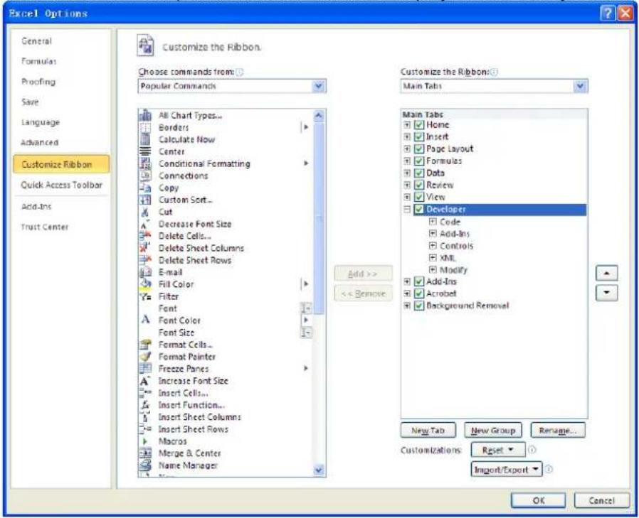
- Input the USB ID into a cell of the Excel file. Click the Developer menu and select the Visual Basic option to open the Microsoft Visual Basic.
- Select Tools(T) in the Microsoft Visual Basic menu bar and click References. In the displayed dialog box, select VISA Library, and click OK to refer to VISA Library.
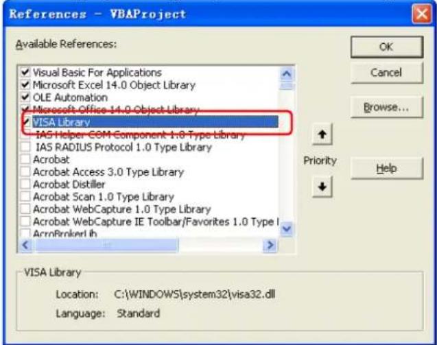
Remarks:
If you cannot find VISA Library in the left section of the above dialog box, please follow the method below to find it.
(1) Make sure that your PC has installed the NI-VISA library.
(2) Click Browse... at the right section to search visa32.dll from C:\WINDOWS\system32, as shown in the figure below.
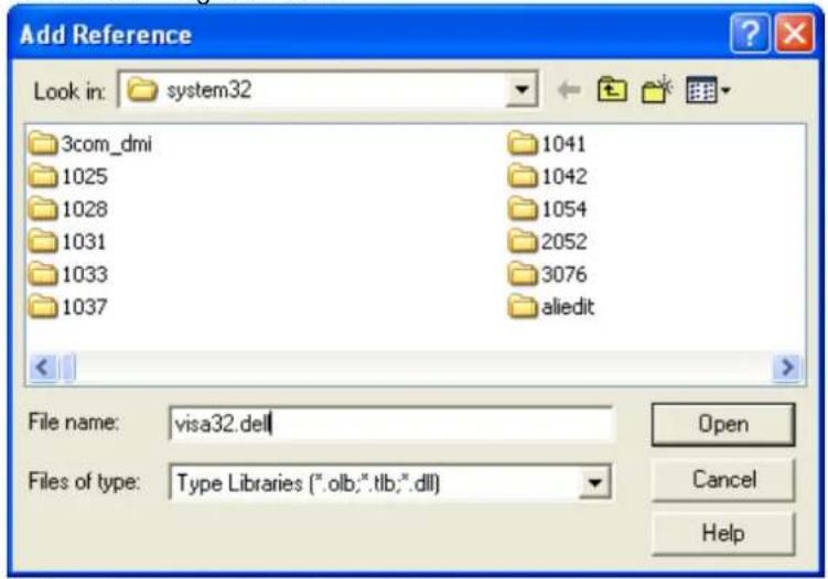
- Click View Code under Developer menu to enter the interface of Microsoft Visual Basic. Add the following codes (the parts in green are the explanations) to the DG800_Demo_Excel.xlsm - Sheet1 (code) window and save it.
Sub QueryIdn()
Dim viDefRm As Long
Dim viDevice As Long
Dim viErr As Long
Dim cmdStr As String
Dim idnStr As String * 128
Dim ret As Long
'Turn on the device, and the device resource descriptor is in CELLS(1,2) of SHEET1'
viErr = visa.viOpenDefaultRM(viDefRm)
viErr = visa.viOpen(viDefRm, Sheet1.Cells(1, 2), 0, 5000, viDevice)
'Send request, read the data, and the return value is in CELLS(2,2) of SHEET1'
cmdStr = "*IDN?"
viErr = visa.viWrite(viDevice, cmdStr, Len(cmdStr), ret)
viErr = visa.viRead(viDevice, idnStr, 128, ret)
Sheet1.Cells(2, 2) = idnStr
'Turn off the device'
visa.viClose (viDevice)
visa.viClose (viDefRm)
End Sub
Note: If the Excel file created at Step 2 does not enable the Macros, a prompt message "The following features cannot be saved in macro-free workbooks" will be displayed. In this case, please save the file as a macro-enabled file type (filename with a suffix of ".xlsx").
- Add the button control. Click Insert under the Developer menu, and select a button control under the Form Controls menu item and put it into the Excel cell. At this time, the Assign Macro dialog box is displayed, select "Sheet1.QueryIdn" and click OK.
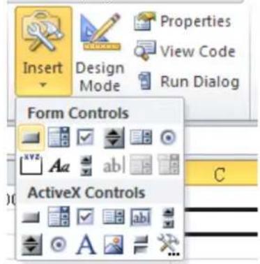
The default name of the button is "Button1". Right-click the button and select Edit Text in the pop-up menu to change the button name to "*IDN?".
- Click the *IDN? button inserted into the Excel file in the last step to run the program and the device information is returned.
| C1 | fx | ||||
| A | B | C | D | E | |
| 1 | Device: | USB0::0x1AB1::0x0642::DG80000000001::INSTR | *IDN? | ||
| 2 | Rigol Technologies, DG832, DG80000000001, 01. 00. 01. 00. 02 | ||||
| 3 | |||||
Matlab Programming Example
Program used in this example: MATLAB R2009a
Function realized in this example: query the current waveform type as well as the waveform frequency, amplitude, offset, and phase of CH1.
- Run the Matlab software and modify the current path (Current Directory). In this example, modify the current path to E:\DG800_Demo_Matlab.

- Click File → New → Blank M-File in the Matlab interface to create an empty M file.
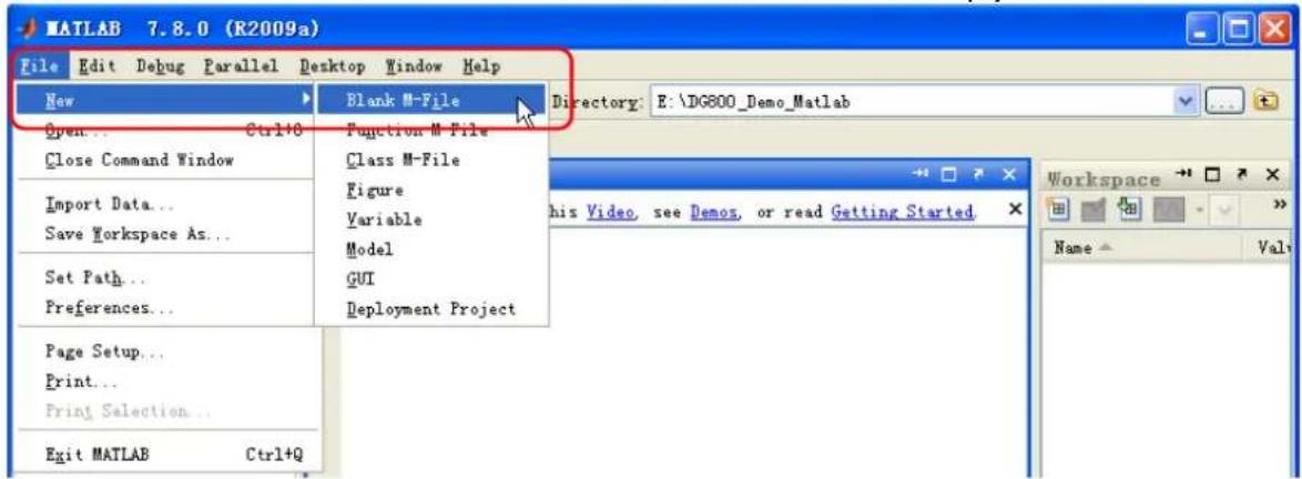
- Add the following codes to the M file:
DG800= visa('ni','USB0::0x1AB1::0x0642::DG80000000001::INSTR'); %create VISAobject
fopen(DG800); %open a created VISA object
fprintf(DG800, ':SOURce1:APPLy?'); %%Send a request
query_CH1 = fscanf(DG800); %Query data
fclose(DG800); %close the VISA object
display(query_CH1) %display the device information already read
- Save the M file to the current path. In this example, the M file is named as "DG800_Demo_MATLAB.m".
- Run the M file. The running results are displayed as follows:
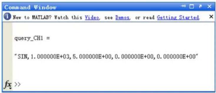
LabVIEW Programming Example
Program used in this example: LabVIEW 2009
Function realized in this example: search for the instrument address, connect to the instrument, send and read commands.
- Run LabVIEW 2009, and then create a VI file named DG800_Demo_LABVIEW.
- Add controls to the front panel interface, including the Address field, Command field, and Return field, the Connect button, the Write button, the Read button, and the Exit button.
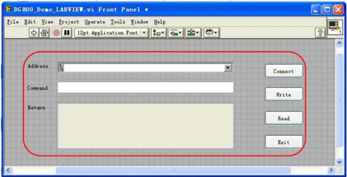
- Click Show Block Diagram under the Window menu to create an event structure.
![DG800_Demo_LABVIEW.vi Front Panel * File Edit View Project Operate Tools Window Help Show Block Diagram Ctrl+E Show Project Tile Left and Right Ctrl+T Tile Up and Down Full Size Ctrl+// 1 DG800_Demo_LABVIEW.vi Front Panel * 2 DG800_Demo_LABVIEW.vi Block Diagram * 3 DemoForDG LV82 [DemoForDG LV82.vi] Front Panel * All Windows... Ctrl+Shift+W Address 1% Command Return Read Exit](/content/2026/05/979841/images/84bd3991a21696b649b0db19f7568a7320fa09552f4b60930521b15e2cdde72a.jpg)
![DG800_Demo_LABVIEW.vi Block Diagram * File Edit View Project Operate Tools Window Help Address Command Return Connect Write Read Exit I/O abc abc TF TF TF TF [0] Timeout Type Time](/content/2026/05/979841/images/dd08992bc6c7e7079c931b118fd2e45ae057199eccbacc0935a4ddcb0d02c02f.jpg)
- Add the events (including connecting to the instrument, write operation, read operation, and exit)
(1) Connect (including error correction advice):
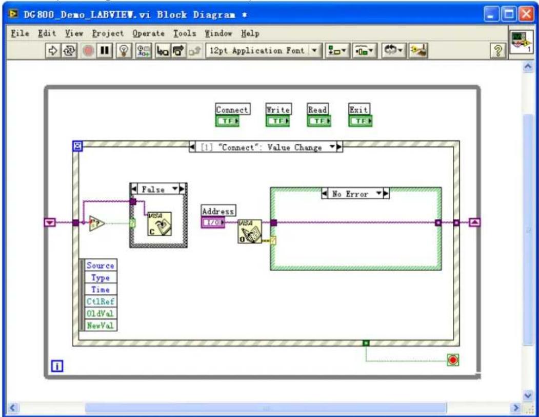
flowchart
graph TD
    A["Source"] --> B["Type"]
    B --> C["Time"]
    C --> D["Ct1Ref"]
    D --> E["OldVal"]
    E --> F["NewVal"]
    G["False"] --> H["VISA"]
    I["Address"] --> J["VISA"]
    K["No Error"] --> L["End"]
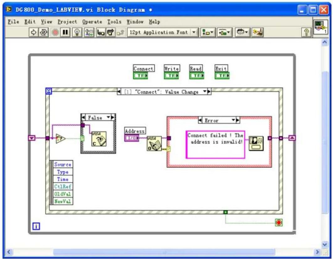
flowchart
graph TD
    A["Source"] --> B["Type"]
    B --> C["Time"]
    C --> D["Ct1Ref"]
    D --> E["OldVal"]
    E --> F["NewVal"]
    G["False"] --> H["VISA"]
    I["Address"] --> J["I/O"]
    K["Error"] --> L["Connect failed! The address is invalid!"]
    M["Connect"] --> N["TF"]
    O["Write"] --> P["TF"]
    Q["Read"] --> R["TF"]
    S["Exit"] --> T["TF"]
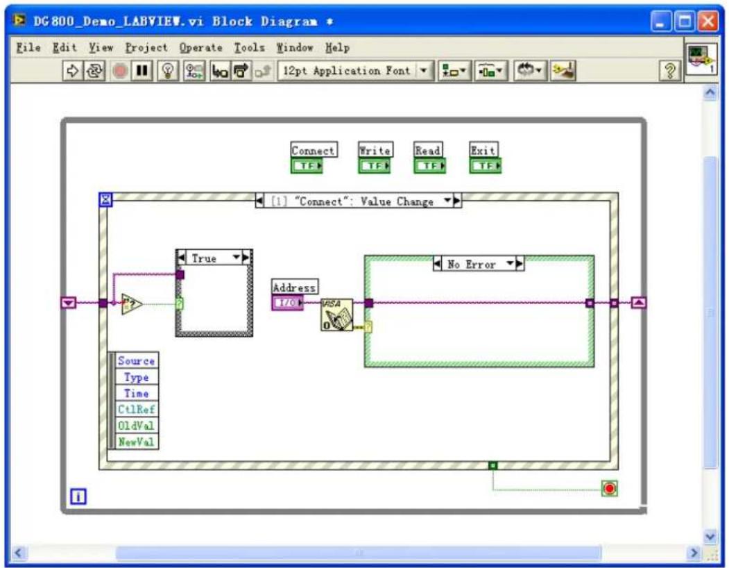
flowchart
graph TD
    A["Source"] --> B["True"]
    C["Type"] --> B
    D["Time"] --> B
    E["Ct1Ref"] --> B
    F["OldVal"] --> B
    G["NewVal"] --> B
    B --> H["Address I/O"]
    H --> I["No Error"]
    I --> J["Connect TF Write TF Read TF Exit TF"]
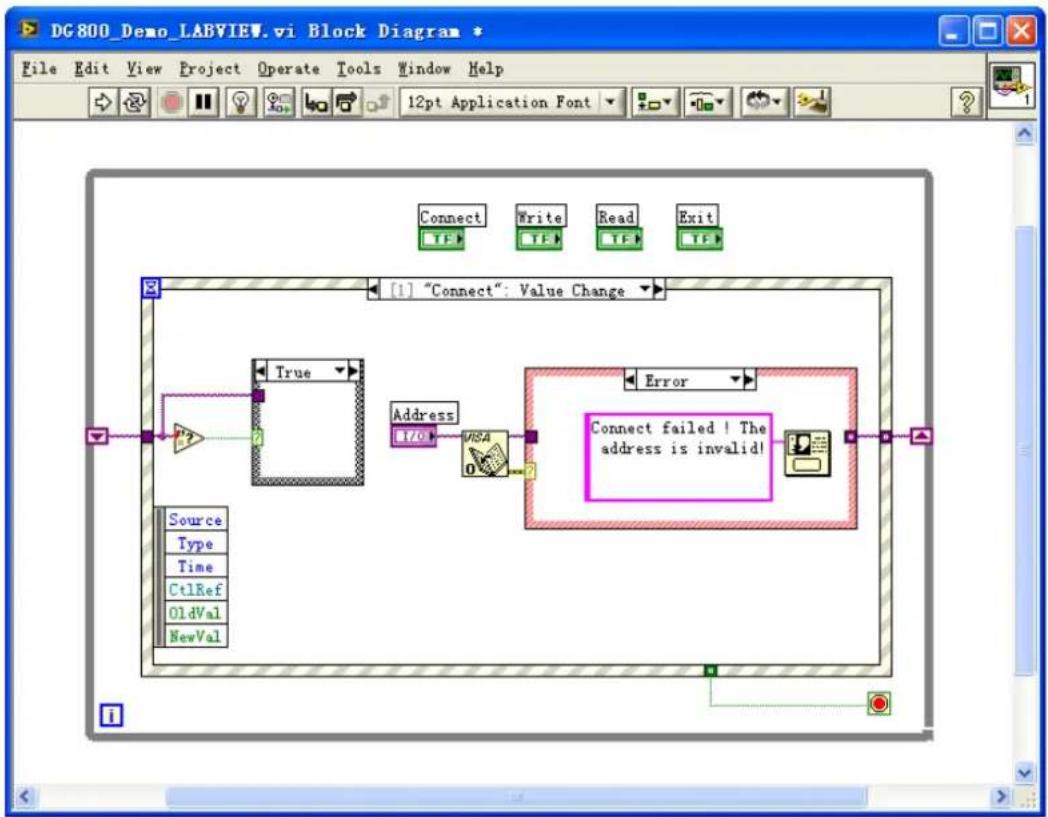
flowchart
graph TD
    A["Source<br>Type<br>Time<br>CtrlRef<br>OldVal<br>NewVal"] --> B["True"]
    B --> C["Address<br>I70"]
    C --> D{Connect failed! The address is invalid!}
    D --> E["Error"]
    E --> F["Connect"]
    style D fill:#f9f,stroke:#333
(2) Write operation (including error confirmation):
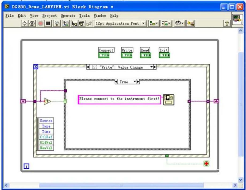
flowchart
graph TD
    A["Source"] --> B["Type"]
    B --> C["Time"]
    C --> D["Ct1Ref"]
    D --> E["OldVal"]
    E --> F["NewVal"]
    G["Connect"] --> H["Write"]
    H --> I["Read"]
    I --> J["Exit"]
    K["True"] --> L["Please connect to the instrument first!"]
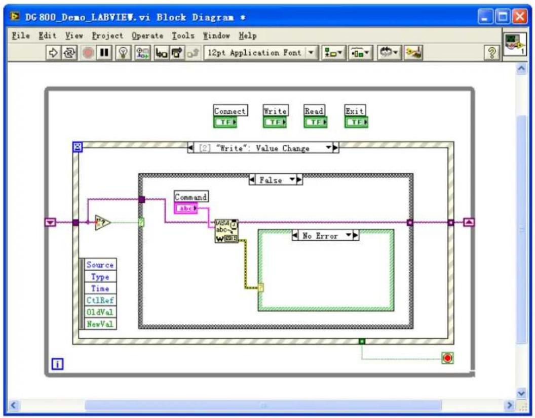
flowchart
graph TD
    A["Source"] --> B["Command"]
    B --> C["alpha"]
    C --> D["No Error"]
    D --> E["Output"]
    style A fill:#f9f,stroke:#333
    style B fill:#ccf,stroke:#333
    style C fill:#cfc,stroke:#333
    style D fill:#fcc,stroke:#333
    style E fill:#ffc,stroke:#333
(3) Read operation (including error processing):
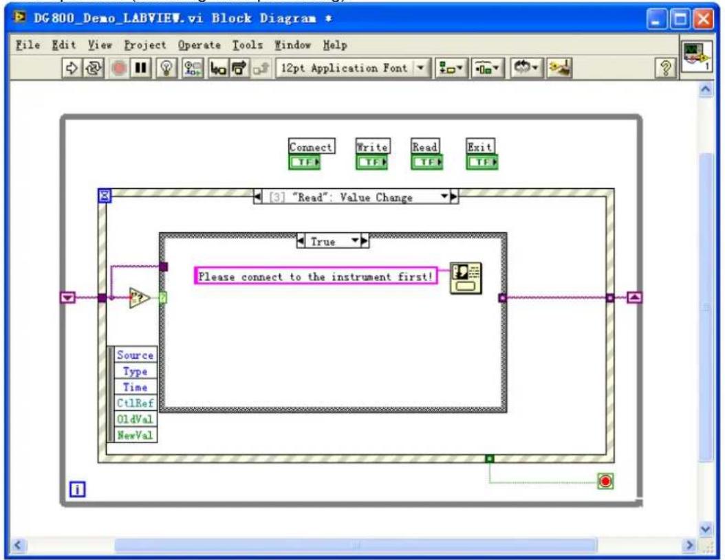
flowchart
graph TD
    A["Source"] --> B["Type"]
    B --> C["Time"]
    C --> D["Ct1Ref"]
    D --> E["OldVal"]
    E --> F["NewVal"]
    G["Connect"] --> H["Write"]
    H --> I["Read"]
    I --> J["Exit"]
    K["True"] --> L["Please connect to the instrument first!"]
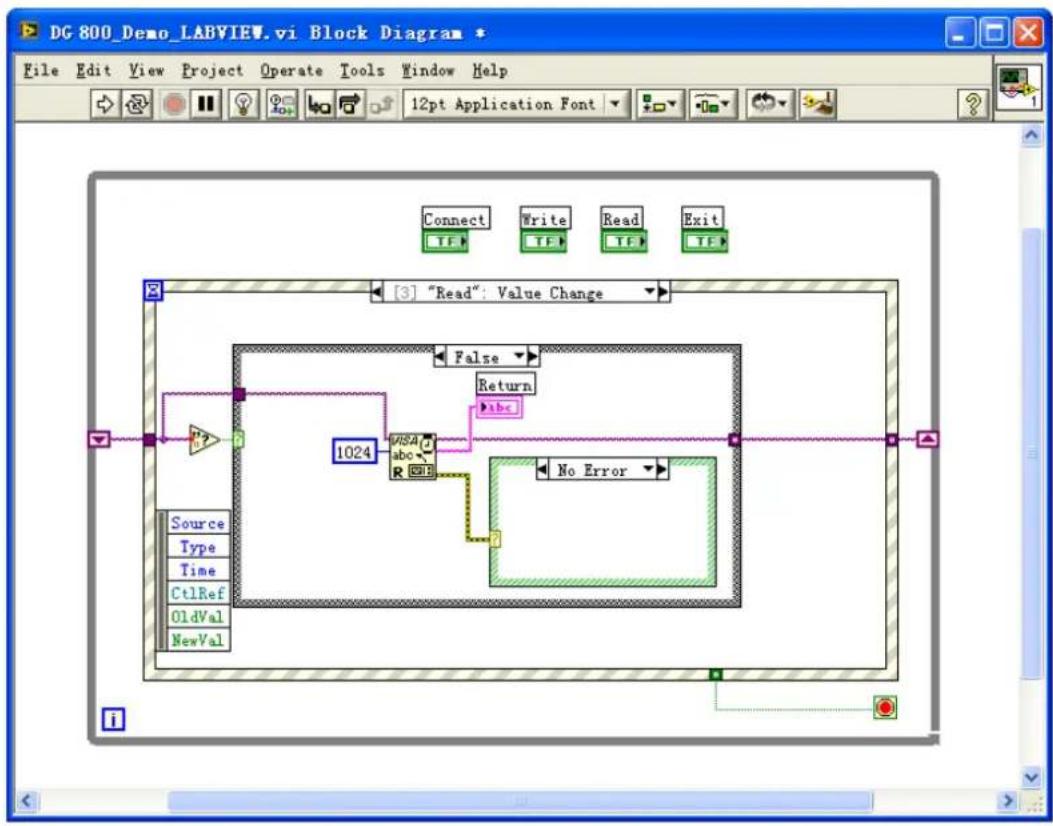
flowchart
graph TD
    A["Source"] --> B["Type"]
    B --> C["Time"]
    C --> D["Ct1Ref"]
    D --> E["OldVal"]
    E --> F["NewVal"]
    F --> G["1024"]
    G --> H["No Error"]
    H --> I["Return"]
    I --> J["abc"]
    J --> K["False"]
    K --> L["[3"] "Read": Value Change]
(4) Exit:
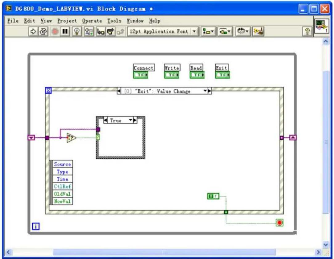
flowchart
graph TD
    A["Source"] --> B["Type"]
    B --> C["Time"]
    C --> D["Ct1Ref"]
    D --> E["OldVal"]
    E --> F["NewVal"]
    F --> G["Exit"]
    style A fill:#f9f,stroke:#333
    style G fill:#ccf,stroke:#333
    note right of A: "Value Change"
    note left of A: "Connect"
    note right of G: "End"
- Run the program, and then the following interface is displayed below. Click the VISA resource name from the drop-down list under Address, and click Connect to connect the instrument. Then, input
* IDN? in the Command field. Click Write to write the command to the instrument. If it is a query command, click Read, and then the query result will be displayed in the Return field.
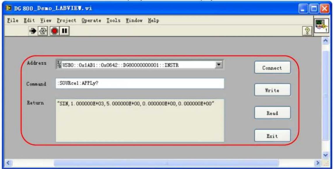
Visual Basic Programming Example
Program used in this example: Visual Basic 6.0
Function realized in this example: enable the two channels of the signal generator and show the corresponding colors of the channels.
-
Run Visual Basic 6.0, and build a standard application program project (Standard EXE), and name it "DG800_Demo_VB".
-
Click Project→Add Module to open the Add Module dialog box. In the dialog box, click the Existing tab to search for the visa32.bas file from the "include" folder under the NI-VISA installation path and add the file.
![Project1 - Microsoft Visual Basic [design] File Edit View Project Format Debug Run Query Diagram Tools Add-Ins Window Help Add Form Add MDI Form Add Module Add Class Module Add User Control General Project - Project1](/content/2026/05/979841/images/bc4e451fa21e429ae963bd962bc34a696534c6a12c79c2f44eca44e69b52bdda.jpg)
- Add two Command Button controls to represent CH1 and CH2 respectively. Add two Label controls (Label1(0) and Label1(1)) to represent the status of the two channels respectively (by default, the Label control is gray; when the channel is enabled, it displays the corresponding color of the channel). The layout of the controls is as shown in the figure below.
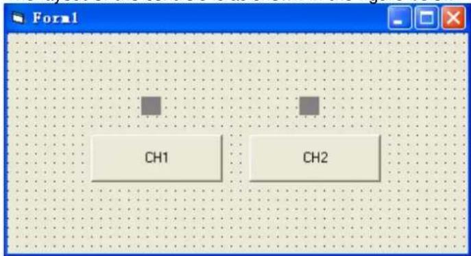
- Click Project→Project1 Properties to open the Project1 – Project Properties dialog box. In the dialog box, click on the General tab and select Form1 from the drop-down list under Startup Object.
![Project1 - Microsoft Visual Basic [design] File Edit View Project Format Debug Run Query Diagram Tools Add-Ins Window Help Add Form Add MDI Form Add Module Add Class Module Add User Control Add Property Page Add User Document Add WebClass Add Data Report Add DHTML Page Add Data Environment More ActiveX Designers... Add File... Ctrl+D Remove DG800_Demo_VB.frm References... Components... Ctrl+T Project1 Properties... CH2 Project1 (DG800_Demo_VB Forms Form1 (DG800_Demo_' Modules Properties - Label1 (0) Label1(0) Label](/content/2026/05/979841/images/e212a1a2887c2b2a332c7155844d71b708e29e17346e42025dd4dfd1432e6ad3.jpg)
- Double-click CH1 to enter the programming environment. Add the following codes to control CH1 and CH2. The codes of CH1 are as shown below; the codes of CH2 are similar.
Dim defrm As Long
Dim vi As Long
Dim strRes As String * 200
Dim list As Long
Dim nmatches As Long
Dim matches As String * 200
' Obtain the usb resource of visa
Call viOpenDefaultRM(defrm)
Call viFindRsrc(defrm, "USB?*", list, nmatches, matches)
'Turn on the instrument
Call viOpen(defrm, matches, 0, 0, vi)
' Send a command to query the status of CH1
Call viVPrintf(vi, ":OUTP1?" + Chr\$(10), 0)
' Acquire the status of CH1
Call viVScanf(vi, "%t", strRes)
If strRes = "ON" Then
' Send the setting command
Call viVPrintf(vi, ":OUTP1 OFF" + Chr\$(10), 0)
Label1(0).ForeColor = &H808080 'Gray
Else
Call viVPrintf(vi, "OUTP1 ON" + Chr\$(10), 0)
Label1(0).ForeColor = &HFFFF& 'Yellow
End If
' Close the resource
Call viClose(vi)
Call viClose(defrm)
- Run and view the results, as shown in the figure below.
![Project1 - Microsoft Visual Basic [design] File Edit View Project Format Debug Run Query Diagram Tools Add-Ins Window Help Start](/content/2026/05/979841/images/b63b58ff7c49220d12d8cf880e6f993611bcac76c0004b4e70d0a364c22e2862.jpg)
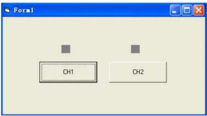
1) Click the CH1 button to enable CH1, and the label above CH1 turns red;
2) Click the CH2 button to enable CH2, and the label above CH2 turns blue;
The running result is as shown in the figure below.
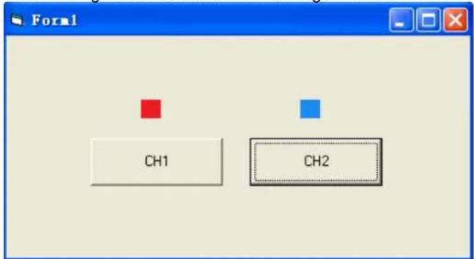
Visual C++ Programming Example
Program used in this example: Microsoft Visual C++ 6.0
Function realized in this example: search for the instrument address, connect to the instrument, send and read commands.
- Run Microsoft Visual C++ 6.0. Create a MFC project based on a dialog box and name it "DG800_Demo_VC".
- Click Project → Settings and add visa32.lib in the Link tab in the pop-up interface manually.
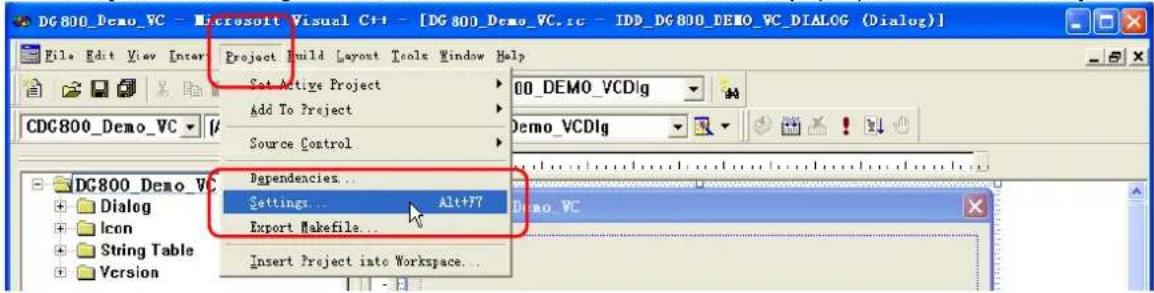
3. Click Tools→Options.
![DG800_Demo_VC - Microsoft Visual C++ - [DG 800 Demo_VC.rc - IDD DG800 DEMO VC_DIALOG (Dialog)] File Edit View Insert Project Build Layout Tools Window Help CDG800_Demo_VC | (All class members) DG800_Demo_VC resources Dialog Icon String Table Version Source Browser... Alt+F12 Close Source Browser File Visual Component Manager Register Control Error Lookup ActiveX Control Test Container OLE/COM Object Viewer Sxy++ MFC Tracer Customire... Options... Macro... Record Quick Macro Ctrl+Shift+P Play Quick Macro Ctrl+Shift+P](/content/2026/05/979841/images/2f1526ca6ecb7f066fb59b0b16f970956a2e850a6b7d2ad33373efcf4c01bbf4.jpg)
Add the Include and Lib paths in the Directories tab in the pop-up interface.
Note:
The two paths added here are related to the installation path of NI-VISA on your PC. By default, NI-VISA is installed under C:\Program Files\IVI Foundation\VISA.
Select Include files from the drop-down list under Show directories for. Double click the empty space under Directories to enter the specified path of Include files: C:\Program Files\IVI Foundation\VISA\WinNT\include. Click OK to close the dialog box.
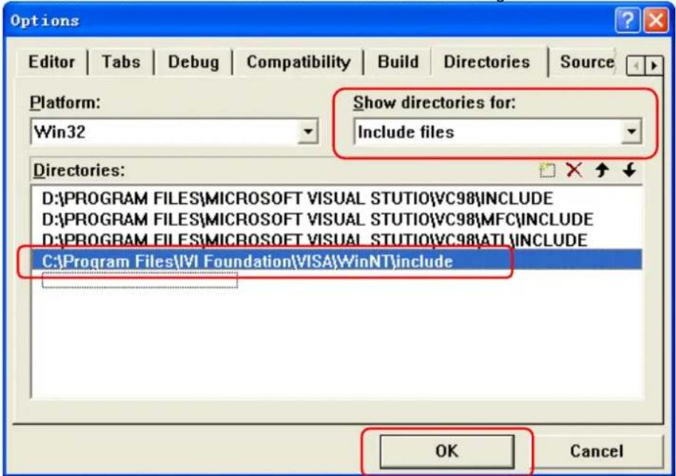
Select Library files from the drop-down list under Show directories for. Double click the empty space under Directories to enter the specified path of Library files: C:\Program Files\IVI Foundation\VISA\WinNT\lib\msc. Click OK to close the dialog box.
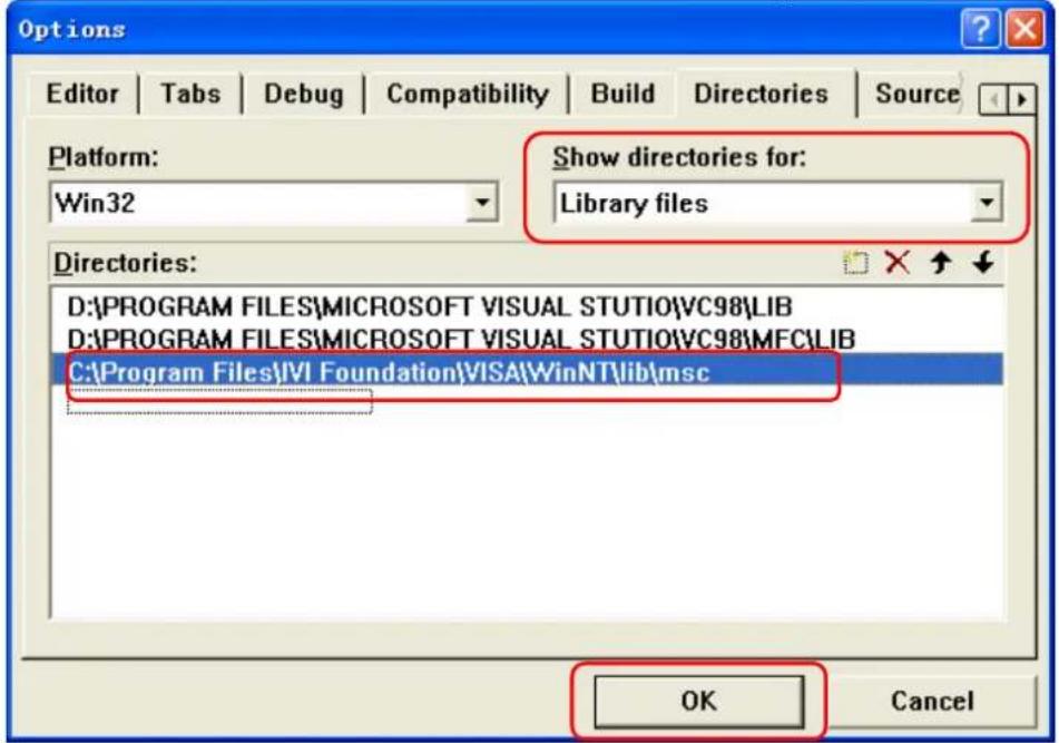
- Add the Text, Edit, and Button controls and the layout is as shown in the figure below. Address, Command and Return are Text controls; Connect, Send and Read are Button controls; the three Edit are Edit controls, and the third Edit control is read-only.
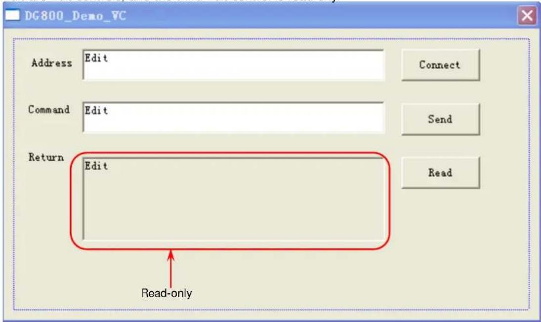
- Click View→ClassWizard and add the control variables in the Member Variables tab in the pop-up interface.
Instrument address: CString m_strInstrAddr
Command CString m_strCommand
Returned value CString m_strResult
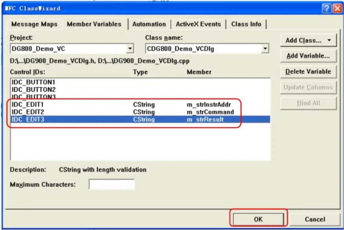
- Encapsulate the read and write operations of VISA.
1) Encapsulate the write operation of VISA for easier operation.
bool CDG800_Demo_VCDlg::InstrWrite(CString strAddr, CString strContent) //write function
{
    ViSession defaultRM, instr;
    ViStatus status;
    ViUInt32 retCount;
    char * SendBuf = NULL;
    char * SendAddr = NULL;
    bool bWriteOK = false;
    CString str;

    //Change the address's data style from CString to char*
    SendAddr = strAddr.GetBuffer(strAddr.GetLength());
    strcpy(SendAddr,strAddr);
    strAddr.ReleaseBuffer();

    //Change the command's data style from CString to char*
    SendBuf = strContent.GetBuffer(strContent.GetLength());
    strcpy(SendBuf,strContent);
    strContent.ReleaseBuffer();

    //open the VISA instrument
    status = viOpenDefaultRM(&defaultRM);
    if (status < VI_SUCCESS)
    {
    AfxMessageBox("No VISA instrument was opened !");
return false;
}

status = viOpen(defaultRM, SendAddr, VI_NULL, VI_NULL, &instr);
//write command to the instrument
status = viWrite(instr, (unsigned char *)SendBuf, strlen(SendBuf), &retCount);

//close the instrument
status = viClose(instr);
status = viClose(defaultRM);

return bWriteOK;
}

2) Encapsulate the read operation of VISA for easier operation.
bool CDGDG800_Demo_VCDlg::InstrRead(CString strAddr, CString *pstrResult)
//Read from the instrument
{
ViSession defaultRM,instr;
ViStatus status;
ViUInt32 retCount;
char * SendAddr = NULL;
unsigned char RecBuf[MAX_REC_SIZE];
bool bReadOK = false;
CString str;

//Change the address's data style from CString to char*
SendAddr = strAddr.GetBuffer(strAddr.GetLength());
strcpy(SendAddr,strAddr);
strAddr.ReleaseBuffer();

memset(RecBuf,0,MAX_REC_SIZE);

//open the VISA instrument
status = viOpenDefaultRM(&defaultRM);
if (status < VI_SUCCESS)
{
    // Error Initializing VISA...exiting
    AfxMessageBox("No VISA instrument was opened !");
    return false;
}

//open the instrument
status = viOpen(defaultRM, SendAddr, VI_NULL, VI_NULL, &instr);

//read from the instrument
status = viRead(instr, RecBuf, MAX_REC_SIZE, &retCount);

//close the instrument
status = viClose(instr);
status = viClose(defaultRM);

(*pstrResult).Format("%s", RecBuf);

return bReadOK;
}
- Add the control message response codes.
1) Connect to the instrument
void CDG800_Demo_VCDlg::OnConnect()
{
    // TODO: Add your control notification handler code here
    ViStatus status;
    ViSession defaultRM;
    ViString expr = "?"";
    ViPFindList findList = new unsigned long;
    ViPUInt32 retcnt = new unsigned long;
    ViChar instrDesc[1000];
    CString strSrc = "";
    CString strInstr = "";
    unsigned long i = 0;
    bool bFindDG = false;

    status = viOpenDefaultRM(&defaultRM);
    if (status < VI_SUCCESS)
    {
    // Error Initializing VISA...exiting
    MessageBox("No VISA instrument was opened ! ");
    return ;
    }

    memset(instrDesc, 0, 1000);

    // Find resource
    status = viFindRsrc(defaultRM, expr, findList, retcnt, instrDesc);

    for (i = 0; i < (* retcnt); i++)
    {
    // Get instrument name
    strSrc.Format("%s", instrDesc);
    InstrWrite(strSrc, "*IDN?");
    ::Sleep(200);
    InstrRead(strSrc, &strInstr);

    // If the instrument(resource) belongs to the DG series then jump out from the loop
    strInstr.MakeUpper();
    if (strInstr.Find("DG") >= 0)
    {
    bFindDG = true;
    m_strInstrAddr = strSrc;
    break;
    }

    // Find next instrument
    status = viFindNext(*findList, instrDesc);
    }

    if (bFindDG == false)
    {
    MessageBox("Didn't find any DG!");
    }
    UpdateData(false);
    }

    2) Write Operation
    void CDG800_Demo_VCDlg::OnSend()
{
    // TODO: Add your control notification handler code here
    UpdateData(true);
    if (m_strInstrAddr.IsEmpty())
    {
    MessageBox("Please connect to the instrument first!");
    }
    InstrWrite(m_strInstrAddr, m_strCommand);
    m_strResult.Empty();
    UpdateData(false);
    }

    3) Read Operation
    void CDG800_Demo_VCDlg::OnRead()
    {
    // TODO: Add your control notification handler code here
    UpdateData(true);
    InstrRead(m_strInstrAddr, &m_strResult);
    UpdateData(false);
}
- Run the program and enter the following operation interface.
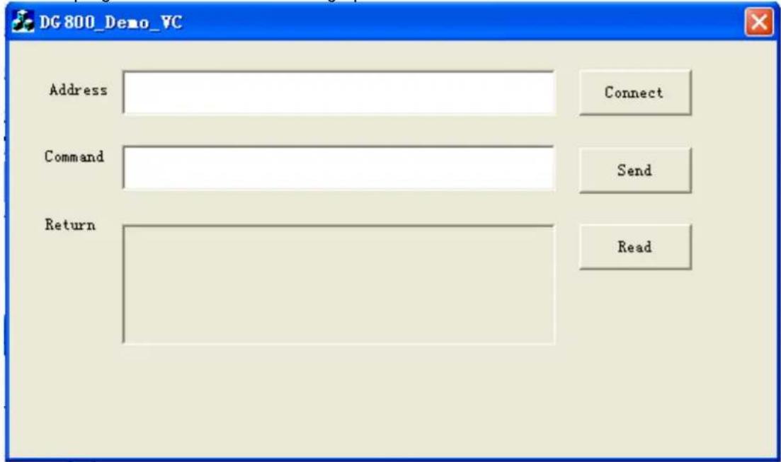
Perform the following steps:
1) Click the Connect button to search for the signal generator and connect it;
2) Input "*IDN?" in the "Command" edit box;
3) Click the Send button to send the command;
4) Click Read to read the returned value.
The execution result is as shown in the figure below.
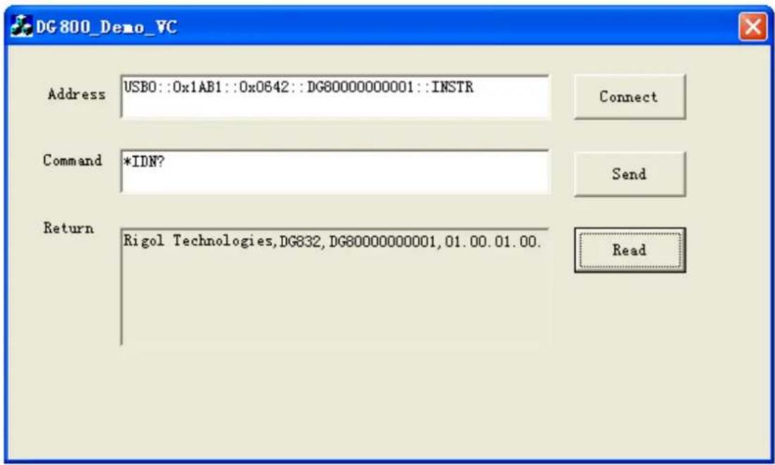
Chapter 5 Appendix
Appendix A: Factory Setting
The factory settings are as shown in the table below. Note that the item with "*" is the factory default value, and its value is related to the user setting during its usage but not affected by the reset operation.
| Parameter | Factory Settings |
| Channel Parameter | |
| Current Carrier Waveform | Sine |
| Output Impedance | HighZ |
| Output Load | 50 Ω |
| Channel Output | Off |
| Output Inverted | Off |
| Level Limit | Off |
| HighL Limit | 0 V |
| LowL Limit | 0 V |
| SyncState | Off |
| Sync Polarity | Negative |
| Freq Cpl | Off |
| FreqCplMode | Deviation |
| Freq Dev | 0 μHz |
| Freq Ratio | 1 |
| Ampl Cpl | Off |
| AmplCplMode | Deviation |
| Ampl Dev | 0 Vpp |
| Ampl Ratio | 1 |
| Phase Cpl | Off |
| PhaseCplMode | Deviation |
| Phase Dev | 0° |
| Phase Ratio | 1 |
| Trig Coupling | Off |
| Track Mode | Off |
| Combine | Off |
| Waveform | Sine |
| Freq | 1 kHz |
| Ratio | 10% |
| Basic Waveforms | |
| Frequency | 1 kHz |
| Amplitude | 5 Vpp |
| Amplitude Unit | Vpp |
| Offset | 0 Vdc |
| Phase | 0° |
| Square Duty Cycle | 50% |
| Ramp Waveform Symmetry | 50% |
| Pulse Duty Cycle | 50% |
| Pulse Width | 500 μs |
| Pulse Rising Edge | 10 ns |
| Pulse Falling Edge | 10 ns |
| Harmonic Type | Even |
| Harmonic Order | 2 |
| Harmonic Phase (7) | 0° |
| Harmonic No. | 2 |
| Harmonic Amplitude (7) | 1.2647 Vpp |
| User | X0000000 |
| DC Offset | 0 V_dc |
| Built-in Arbitrary Waveforms | Sinc |
| Advanced Waveform | |
| Amplitude | 5 Vpp |
| Offset | 0 V_dc |
| PRBS Bit Rate | 2 kbps |
| PRBS Data | PRBS7 |
| RS232 Baud Rate | 9600 |
| RS232 Data Bits | 8 |
| RS232 Stop Bits | 1 |
| RS232 Parity Bit | None |
| RS232 Data | 85 |
| Sequence Filter | Interpolation |
| Sequence Sample Rate | 1 MSa/s |
| Sequence Phase | 0° |
| Modulation | |
| AM Modulation | |
| Source | Internal |
| Mod.Wave | Sine |
| Mod.Freq | 100 Hz |
| Mod.Depth | 100% |
| DSSC | Off |
| FM Modulation | |
| Source | Internal |
| Mod.Wave | Sine |
| Mod.Freq | 100 Hz |
| Freq.Dev | 1 kHz |
| PM Modulation | |
| Source | Internal |
| Mod.Wave | Sine |
| Mod.Freq | 100 Hz |
| Phas.Dev | 90° |
| ASK Modulation | |
| Source | Internal |
| Mod.Rate | 100 Hz |
| Mod.Ampl | 2 Vpp |
| Polarity | Positive |
| FSK Modulation | |
| Source | Internal |
| Mod.Rate | 100 Hz |
| Hop Freq | 10 kHz |
| Polarity | Positive |
| PSK Modulation | |
| Source | Internal |
| Mod.Rate | 100 Hz |
| Phase | 180° |
| Polarity | Positive |
| PWM Modulation | |
| Source | Internal |
| Mod.Wave | Sine |
| Mod.Freq | 100 Hz |
| Width Deviation | 200 μs |
| Duty Deviation | 20% |
| Sweep | |
| Sweep Time | 1 s |
| Return Time | 0 ms |
| Start Freq | 100 Hz |
| Stop Freq | 1 kHz |
| Center Frequency | 550 Hz |
| Frequency Span | 900 Hz |
| Start Hold Time | 0 ms |
| Stop Hold Time | 0 ms |
| Marker | Off |
| Marker Freq | 550 Hz |
| Trigger Source | Internal |
| Trig In | RisEdge |
| Step | 2 |
| Burst | |
| Cycles | 1 |
| Period | 10 ms |
| Gated Polarity | Positive |
| Idle Level | 1^st Point |
| Trigger Source | Internal |
| Trig Out | Off |
| Trig In | RisEdge |
| Delay | 0 ns |
| Interface Focus Items | |
| Freq/Period | Freq |
| Ampl/HighL | Ampl |
| Offset/LowL | Offset |
| Duty/Width | Duty |
| Start/Center | Start |
| Stop/Span | Stop |
| Default Channel | CH1 |
| Frequency Counter | |
| Meas.Para | Freq |
| GateTime | 100 ms |
| Statistics | Off |
| Sensitivity | Low |
| Trig Level | 0 V |
| Coupling | DC |
| High Freq Rejection | Off |
| System Parameter | |
| System Setting | |
| Language* | Determined by Factory Delivery Setting |
| Power-on | Default |
| Clk Source | Internal |
| Beeper | On |
| Decimal | Dot |
| Delimiter | Comma |
| System Log | Off |
| DispSet | |
| Screen Saver | Off |
| Brightness* | 100% |
| Print Setting | |
| Location | USB Storage Device |
| Format* | PNG |
| Interface | |
| GPIB* | 2 |
| DHCP* | On (default setting in LAN) |
| Auto IP* | On (default setting in LAN) |
| Manual IP* | Off (default setting in LAN) |
Appendix B: Warranty
RIGOL (SUZHOU) TECHNOLOGIES INC. (hereinafter referred to as RIGOL) warrants that the product will be free from defects in materials and workmanship within the warranty period. If a product proves defective within the warranty period, RIGOL guarantees free replacement or repair for the defective product.
To get repair service, please contact with your nearest RIGOL sales or service office.
There is no other warranty, expressed or implied, except such as is expressly set forth herein or other applicable warranty card. There is no implied warranty of merchantability or fitness for a particular purpose. Under no circumstances shall RIGOL be liable for any consequential, indirect, ensuing, or special damages for any breach of warranty in any case.
- Function/ Arbitrary Waveform Generator
- Guaranty and Declaration
- Copyright
- Trademark Information
- Publication Number
- Software Version
- Notices
- Product Certification
- Contact Us
- Document Overview
- Main Topics in this Manual:
- Chapter 1 Programming Overview
- Chapter 2 Command System
- Chapter 3 Application Instances
- Chapter 4 Programming Examples
- Chapter 5 Appendix
- Tip
- Format Conventions in this Manual:
- Keys:
- Menu Labels:
- Operation Procedures:
- Content Conventions in this Manual:
- Contents
- Guaranty and Declaration.... I
- Document Overview ......II
- Chapter 1 Programming Overview.... 1-1
- Chapter 2 Command System.... 2-1
- Chapter 3 Application Instances.... 3-1
- Chapter 4 Programming Examples ....4-1
- Chapter 5 Appendix ....5-1
- Contents in this chapter:
- Build Remote Communication
- Operation Procedures:
- Install Ultra Sigma (PC) software
- Connect the analyzer to the PC and configure the interface parameters for the instrument DG800 supports the USB, LAN (extended from the USB HOST interface by using the USB-LAN interface converter), and GPIB (extended from the USB HOST interface by using the USB-GPIB interface converter) communication interfaces, as shown in the figure below.
- Check whether the connection is successful
- Remote Control Method
- User-defined programming
- Send SCPI commands via the PC software
- SCPI Command Overview
- Syntax
- Symbol Description
- Braces { }
- Vertical Bar |
- Square Brackets []
- Triangle Brackets <>
- Parameter Type
- Bool
- Integer
- Real
- Discrete
- ASCII String
- Command Abbreviation
- Note:
- :COUNTER Commands
- Command List [1] :
- :COUNTER:AUTO
- Description
- Remarks
- :COUNTER:COUPLING
- Return Format
- Example
- :COUNTER:GATEme
- :COUNTER:HF
- :COUNTER:LEVEI
- :COUNTER:MEASure?
- :COUNTER:SENSitive
- :COUNTER[:STATe]
- :COUNTER:STATI stics:CLEAR
- :COUNTER:STATI stics[:STATE]
- :COUPLing Commands
- Command List:
- :COUPling[]:AMPL:DEViation
- :COUPling[]:AMPL:MODE
- :COUPling[]:AMPL:RATio
- :COUPling[]:AMPL[:STATE]
- :COUPling[]:FREQuency:DEViation
- :COUpling[]:FREQuency:MODE
- :COUPling[]:FREQuency:RATio
- :COUPling[]:FREQuency[:STATE]
- :COUPling[]:PHASe:DEViation
- :COUPling[]:PHASe:MODE
- :COUPling[]:PHASe:RATio
- :COUPling[]:PHASe[:STATe]
- :COUPling[][:STATe]
- :COUPling[]:TRI gger[:STATE]
- :DI SPlay Commands
- :DI SPlay:BRI Ghtness
- :DI SPlay:SAVer:I MMediate
- :DI SPlay:SAVer[:STATE]
- :HCOPy Commands
- :HCOPy:SDUMp:DATA?
- :HCOPy:SDUMp:DATA:FORMAT
- IEEE488.2 Common Commands
- \* CLS
- \* ESE
- \* OPT?
- \* PSC
- \* RCL
- \* RST
- \* SAV
- \* SRE
- \* STB?
- \* TRG
- :LI Cense Commands
- :LI Cense:CLEAR
- :LI Cense:I NSTall
- :LI Cense:SET
- :LI Cense[:STATe]?
- :MEMory Commands
- :MEMory:NSTates?
- :MEMory:STATe:CATalog?
- :MEMory:STATE:DElete
- :MEMory:STATE:NAME
- :MEMory:STATE:RECall:AUTO
- :MEMory:STATE:VALid?
- :MMEMory Commands
- :MMEMory:CATalog[:ALL]?
- :MMEMory:CATalog:DATA:ARBitrary?
- :MMEMory:CATalog:STATe?
- :MMEMory:CDI Rectory
- :MMEMory:COPY
- :MMEMory:DElete
- :MMEMory:DOWNLOAD:FNAME
- :MMEMory:DOWNLOAD:DATA
- :MMEMory:LOAD[:ALL]
- :MMEMory:LOAD:DATA
- :MMEMory:LOAD:STATE
- :MMEMory:MDI Rectory
- :MMEMory:MOVE
- :MMEMory:RDI Rectory?
- :MMEMory:RDI Rectory
- :MMEMory:STORe[:ALL]
- :MMEMory:STORe:DATA
- :MMEMory:STORe:STATe
- :OUTPUT Commands
- :OUTPUT[]:POLarity
- :OUTPUT[][:STATE]
- :OUTPUT[]:SYNC:POLarity
- :OUTPUT[]:SYNC[:STATE]
- :OUTPUT[]:VOLLimit:HI GH
- :OUTPUT[]:VOLLimit:LOW
- :OUTPUT[]:VOLLimit[:STATE]
- :ROSCillator Commands
- :ROSCillator:SOURce
- :ROSCillator:SOURce:CURRENT?
- :SOURce Commands
- :SOURce:APPLy
- [:SOURCE[]]:APPLy:DC
- [:SOURCE[]]:APPLy:DUALTone
- [:SOURCE[]]:APPLy:HARMonic
- [:SOURCE[]]:APPLy:NOI Se
- [:SOURCE[]]:APPLy:PRBS
- [:SOURCE[]]:APPLy:PULSe
- [:SOURCE[]]:APPLy:RAMP
- [:SOURCE[]]:APPLy:RS232
- [:SOURCE[]]:APPLy:SEQUence
- [:SOURCE[]]:APPLy:SI Nusoid
- [:SOURCE[]]:APPLy:SQUare
- [:SOURCE[]]:APPLy:USER
- :SOURce:BURSt
- [:SOURCE[]]:BURSt:GATE:POLarity
- [:SOURCE[]]:BURSt:INTernal:PERiod
- [:SOURCE[]]:BURSt:MODE
- [:SOURCE[]]:BURSt:NCYCles
- [:SOURCE[]]:BURSt:PHASE
- [:SOURCE[]]:BURSt[:STATE]
- [:SOURCE[]]:BURSt:TDELay
- [:SOURce[]]:BURSt:TRIGger[:IMMediate]
- [:SOURCE[]]:BURSt:TRIGger:SLOPe
- [:SOURCE[]]:BURSt:TRIGger:SOURce
- [:SOURCE[]]:BURSt:TRIGger:TRIGOut
- [:SOURCE[]]:BURSt:I DLE
- :SOURce:FREQuency
- [:SOURCE[]]:FREQUENCY:CENTER
- [:SOURCE[]]:FREQUENCY:COUPIe:MODE
- [:SOURce[]]:FREQuency:COUPLE:OFFSET
- [:SOURCE[]]:FREQuency:COUPLE:RATio
- [:SOURCE[]]:FREQUENCY:COUPIe[:STATE]
- [:SOURCE[]]:FREQUENCY[:FI Xed]
- [:SOURCE[]]:FREQUENCY:SPAN
- [:SOURCE[]]:FREQuency:START
- [:SOURCE[]]:FREQuency:STOP
- :SOURce:FUNCTION
- [:SOURCE[]]:FUNCTION:DUALTone:CENTERFreq
- [:SOURCE[]]:FUNCTION:DUALTone:FREQ1
- [:SOURCE[]]:FUNCTION:DUALTone:FREQ2
- [:SOURCE[]]:FUNCTION:DUALTone:OFFSETFreq
- [:SOURCE[]]:FUNCTION:PRBS:BRATe
- [:SOURCE[]]:FUNCTION:PRBS:DATA
- [:SOURCE[]]:FUNCTION:PULSe:DCYCIe
- [:SOURCE[]]:FUNCTION:PULSe:PERiod
- [:SOURCE[]]:FUNCTION:PULSE:TRANSition[:BOTH]
- [:SOURCE[]]:FUNCTION:PULSE:TRANSition:LEADING
- [:SOURCE[]]:FUNCTION:PULSE:TRANSition:TRAiling
- [:SOURCE[]]:FUNCTION:PULSE:WIDTH
- [:SOURCE[]]:FUNCTION:RAMP:SYMMetry
- [:SOURce[]]:FUNCTION:RS232:BAUDrate
- [:SOURCE[]]:FUNCTION:RS232:CHECKBit
- [:SOURCE[]]:FUNCTION:RS232:DATA
- [:SOURCE[]]:FUNCTION:RS232:DATABit
- [:SOURCE[]]:FUNCTION:RS232:STOPBit
- [:SOURCE[]]:FUNCTION:SEQUence:EDGETime
- [:SOURCE[]]:FUNCTION:SEQUence:FI LTer
- [:SOURCE[]]:FUNCTION:SEQUence:PERiod
- [:SOURCE[]]:FUNCTION:SEQUence:SRATe
- [:SOURCE[]]:FUNCTION:SEQUence[:STATE]
- [:SOURCE[]]:FUNCTION:SEQUence:WAVE
- [:SOURCE[]]:FUNCTION[:SHAPe]
- [:SOURCE[]]:FUNCTION:SQUare:DCYCIe
- [:SOURCE[]]:FUNCTION:SQUare:PERiod
- :SOURce:HARMonic
- [:SOURCE[]]:HARMonic:AMPL
- [:SOURCE[]]:HARMonic:ORDEr
- [:SOURCE[]]:HARMonic:PHASE
- [:SOURCE[]]:HARMonic[:STATE]
- [:SOURCE[]]:HARMonic:TYPE
- [:SOURCE[]]:HARMonic:USER
- :SOURce:MARKer
- [:SOURCE[]]:MARKer:FREQuency
- [:SOURCE[]]:MARKer[:STATE]
- :SOURce[:MOD]:AM
- [:SOURCE[]][:MOD]:AM[:DEPTH]
- [:SOURCE[]][:MOD]:AM:DSSC
- [:SOURCE[]][:MOD]:AM:INTernal:FREQuency
- [:SOURCE[]][:MOD]:AM:INTernal:FUNCTION
- [:SOURCE[]][:MOD]:AM:SOURCE
- [:SOURCE[]][:MOD]:AM:STATE
- :SOURce[:MOD]:ASKey
- [:SOURCE[]][:MOD]:ASKey:AMPLitude
- [:SOURCE[]][:MOD]:ASKey:INTernal[:RATE]
- [:SOURCE[]][:MOD]:ASKey:POLarity
- [:SOURCE[]][:MOD]:ASKey:SOURCE
- [:SOURCE[]][:MOD]:ASKey:STATE
- :SOURce[:MOD]:FM
- [:SOURCE[]][:MOD]:FM[:DEViation]
- [:SOURCE[]][:MOD]:FM:INTernal:FREQUENCY
- [:SOURCE[]][:MOD]:FM:INTernal:FUNCTION
- [:SOURCE[]][:MOD]:FM:SOURce
- [:SOURCE[]][:MOD]:FM:STATe
- :SOURce[:MOD]:FSKey
- [:SOURCE[]][:MOD]:FSKey[:FREQuency]
- [:SOURCE[]][:MOD]:FSKey:INTernal:RATE
- [:SOURCE[]][:MOD]:FSKey:POLarity
- [:SOURCE[]][:MOD]:FSKey:SOURCE
- [:SOURCE[]][:MOD]:FSKey:STATE
- :SOURce[:MOD]:PM
- [:SOURCE[]][:MOD]:PM[:DEVIation]
- [:SOURCE[]][:MOD]:PM:INTernal:FREQuency
- [:SOURCE[]][:MOD]:PM:INTernal:FUNCTION
- [:SOURCE[]][:MOD]:PM:SOURce
- [:SOURCE[]][:MOD]:PM:STATE
- :SOURce[:MOD]:PSKey
- [:SOURCE[]][:MOD]:PSKey:INTernal:RATE
- [:SOURCE[]][:MOD]:PSKey:PHASe
- [:SOURCE[]][:MOD]:PSKey:POLarity
- [:SOURCE[]][:MOD]:PSKey:SOURCE
- [:SOURCE[]][:MOD]:PSKey:STATE
- :SOURce[:MOD]:PWM
- [:SOURCE[]][:MOD]:PWM[:DEViation]:DCYCIe
- [:SOURCE[]][:MOD]:PWM[:DEViation][:WIDTh]
- [:SOURCE[]][:MOD]:PWM:INTernal:FREQuency
- [:SOURCE[]][:MOD]:PWM:INTernal:FUNCTION
- [:SOURCE[]][:MOD]:PWM:SOURce
- [:SOURCE[]][:MOD]:PWM:STATE
- :SOURce:MOD
- [:SOURCE[]]:MOD[:STATE]
- [:SOURCE[]]:MOD:TYPE
- :SOURce:PERiod
- [:SOURCE[]]:PERiod[:FI Xed]
- :SOURce:PHASE
- [:SOURCE[]]:PHASe[:ADJust]
- :SOURce:PULSE
- [:SOURCE[]]:PULSe:DCYCl
- [:SOURCE[]]:PULSe:TRANSition[:LEADING]
- [:SOURCE[]]:PULSe:TRANsition:TRAiling
- [:SOURCE[]]:PULSe:WIDTH
- :SOURce:SUM
- [:SOURCE[]]:SUM:AMPLitude
- [:SOURce[]]:SUM:INTernal:FREQuency
- [:SOURCE[]]:SUM:INTernal:FUNCTION
- [:SOURCE[]]:SUM[:STATE]
- :SOURce:SWEep
- [:SOURCE[]]:SWEep:HTI Me:STARt
- [:SOURCE[]]:SWEep:HTIMe[:STOP]
- [:SOURCE[]]:SWEep:RTI Me
- [:SOURCE[]]:SWEep:SPACing
- [:SOURCE[]]:SWEep:STATE
- [:SOURCE[]]:SWEep:STEP
- [:SOURCE[]]:SWEep:TIME
- [:SOURCE[]]:SWEep:TRIGger[:IMMediate]
- [:SOURCE[]]:SWEep:TRIGger:SLOPe
- [:SOURCE[]]:SWEep:TRIGger:SOURce
- :SOURce:TRACe
- [:SOURCE[]][:TRACe]:DATA:DAC16
- :SOURce:TRACK
- [:SOURCE[]]:TRACK
- :SOURce:VOLTage
- [:SOURCE[]]:VOLTage:COUPLE[:STATE]
- [:SOURCE[]]:VOLTage[:LEVel][:IMMediate][:AMPLitude]
- [:SOURCE[]]:VOLTage[:LEVel][:IMMediate]:HIGH
- [:SOURCE[]]:VOLTage[:LEVel][:IMMediate]:LOW
- [:SOURCE[]]:VOLTage[:LEVel][:IMMediate]:OFFSET
- [:SOURCE[]]:VOLTage:UNIT
- :SYSTem Commands
- :SYSTem:BEEPer[:IMMediate]
- :SYSTem:BEEPer:STATe
- :SYSTem:CHANnel:NUMber?
- :SYSTem:COMMunicate:GPI B[:SELF]:ADDRess
- :SYSTem:COMMunicate:LAN:APPLy
- :SYSTem:COMMunicate:LAN:AUTOip[:STATe]
- :SYSTem:COMMunicate:LAN:CONTrol?
- :SYSTem:COMMunicate:LAN:DHCP[:STATe]
- :SYSTem:COMMunicate:LAN:DNS
- :SYSTem:COMMunicate:LAN:GATEway
- :SYSTem:COMMunicate:LAN:IPADdress
- :SYSTem:COMMunicate:LAN:SMASk
- :SYSTem:COMMunicate:LAN:STATic[:STATe]
- :SYSTem:COMMunicate:USB:INFormation?
- :SYSTem:CSCopy
- :SYSTem:ERRor?
- :SYSTem:KLOCk
- :SYSTem:LANGUAGE
- :SYSTem:POWeron
- :SYSTem:PRESet:SAVE
- :SYSTem:PRESet[:STATE]?
- :SYSTem:ROSCillator:SOURce
- :TRIGger Commands
- :TRI Gger[]:DELay
- :TRIGger[][:IMMediate]
- :TRI Gger[]:SLOPe
- :TRI Gger[]:SOURce
- To Output Basic Waveforms
- Requirement
- To Output the Arbitrary Waveform
- To Output Harmonic
- To Output AM Modulated Waveform
- To Output FSK Modulated Waveform
- To Output Sweep Waveform
- To Output Burst Waveform
- To Use the Frequency Counter
- Programming Preparations
- Excel Programming Examples
- Remarks:
- Matlab Programming Example
- LabVIEW Programming Example
- Visual Basic Programming Example
- Visual C++ Programming Example
- Click Tools→Options.
- Appendix A: Factory Setting
- Appendix B: Warranty
Brand : Rigol
Model : DG832
Category : Generator