MULTI-REG CONTROL IP54 - Controller Soler & Palau - Free user manual and instructions
Find the device manual for free MULTI-REG CONTROL IP54 Soler & Palau in PDF.


| Product Type | Controller |
| Brand | Soler & Palau |
| Model | MULTI-REG CONTROL IP54 |
| Protection Rating | IP54 |
| Dimensions (H x W x D) | 200 x 120 x 60 mm |
| Weight | 0.5 kg |
| Power Supply | 230 V AC, 50/60 Hz |
| Power Consumption | 5 W |
| Operating Temperature | -10 °C to +50 °C |
| Material | ABS plastic |
| Display | LED indicators |
| Controls | Rotary knobs and push buttons |
| Control Type | Multi-speed fan speed control |
| Number of Zones | 1 |
| Compatible Fans | Soler & Palau ventilation units |
| Communication Output | 0-10 V or potentiometer |
| Mounting | Wall-mounted |
| Cable Entry | Via cable glands |
| Certifications | CE, RoHS |
| Cleaning | Wipe with a dry cloth |
| Spare Parts | Knobs, PCB, internal fuse |
| Warranty | 2 years |
Frequently Asked Questions - MULTI-REG CONTROL IP54 Soler & Palau
User questions about MULTI-REG CONTROL IP54 Soler & Palau
0 question about this device. Answer the ones you know or ask your own.
Ask a new question about this device
Download the instructions for your Controller in PDF format for free! Find your manual MULTI-REG CONTROL IP54 - Soler & Palau and take your electronic device back in hand. On this page are published all the documents necessary for the use of your device. MULTI-REG CONTROL IP54 by Soler & Palau.
USER MANUAL MULTI-REG CONTROL IP54 Soler & Palau
- RECOMMENDATIONS....5
- TRANSPORT AND HANDLING....5
- GENERAL 5
3.1. Speed Control Inputs 5
3.2. Installer-defined Fixed Speed Control ....5
3.3. Remote Switching....6
3.4. Fan-Fail Detection by Fault Sensing....6
3.5. Outputs....6
3.6. Analog Switch Outputs....6
- SAFETY RULES 6
4.1. WARNING 6
4.2. CAUTION 6
4.3. SPECIFICATION....7
4.4. INSTALLATION....7
-
FAN WIRING 8
-
CONTROL WIRING....9
6.1. REMOTE ENABLE VIA EXTERNAL VOLT-FREE CONTACT 9
6.2. REMOTE ENABLE VIA EXTERNAL SWITCHED 230V SUPPLY 10
6.3. CONTINUOUS RUNNING WITH TWO OPTIONAL SPEEDS VIA EXTERNAL VOLT-FREE CONTACTS ..... 11
6.4. CONTINUOUS RUNNING WITH TWO OPTIONAL SPEEDS VIA EXTERNAL SWITCHED 230V SUPPLY ..... 12
6.5. REMOTE ENABLE AND SPEED CONTROL VIA EXTERNAL REB-ECOWATT 13
6.6. REMOTE ENABLE AND SPEED CONTROL VIA EXTERNAL REB-CVF 14
6.7. CONTINUOUS RUNNING WITH TWO OPTIONAL SPEEDS VIA EXTERNAL SWITCHED 230V SUPPLY ..... 15
6.8. REMOTE ENABLE VIA 7-DAY TIMER (1000001114) 16
6.9. RUN AND FAULT RELAY....17
6.10. FAULT INPUTS 18
6.11. DAMPER....19
6.12. OVER-RUN TIMER 20
6.13. FAN SPEED OFFSET 21
- MAINTENANCE 22
- RECYCLING....22
- EC DECLARATION OF CONFORMITY....22
- DESIGNATION OF EQUIPMENT 22
- GUARANTEE 23
1. RECOMMENDATIONS
Thank you for placing your confidence in S&P by buying this product. It has been manufactured following current technical safety regulations and in compliance with EC standards.
Please read this instruction booklet carefully before installing or starting up the product. It contains important information on personal and user safety measures to be followed while installing, using and carrying out maintenance work on the equipment. Once the product has been installed, please hand this booklet to the end user.
Check that the apparatus is in perfect condition while unpacking. Any fault or damage caused in origin is covered by the S&P guarantee. Please make sure that the apparatus coincides with the product you have ordered and that the details on the characteristics plate fulfil your requirements.
2. TRANSPORT AND HANDLING
- The packaging used for this apparatus has been designed to support normal transporting conditions. The apparatus must always be transported in its original packaging as not doing so could deform or damage the product.
- The product should be stored in a dry place in its original packaging, protected from dust and dirt until it is installed in its final location. Do not accept delivery if the apparatus is not in its original packaging or shows clear signs of having been manipulated in any way.
- Do not place heavy weights on the packed product and avoid knocking or dropping it.
- When handling heavy products, adequate lifting equipment should be used to avoid harming people or damaging the product itself.
- Never lift a product by pulling it by the wires or terminal/control enclosure. Likewise, no pressure should be applied on the impeller, shutter or spigots while handling the product.
3. GENERAL
- The MULTI-REG Control for ECOWATT EC Fans to provide Demand Ventilation Speed Control for dedicated control of the S&P ECOWATT EC ranges and full BMS compatibility.
- For up to two ECOWATT (EC) Fans – the MULTI-REG's 0-10V output signals are routed directly to the fan.
3.1. Speed Control Inputs
• Variable Speed Control
- Manual variable speed control via an optional secondary S&P REB ECOWATT or REB-CVF controller, or
- Automated variable speed control via a 0-10V signal from an external source.
3.2. Installer-defined Fixed Speed Control
- An upon-installation defined duty either continuous or on-demand (triggered by an external switch), or
- One, two or three speeds defined during installation to provide a minimum/middle/maximum speed ventilation system, the middle and maximum speeds being selected by an external switch/sensor (either Volt-free and/or 230V).
- Note that there is a 3-Volt minimum output to the fan to ensure start-up momentum.
3.3. Remote Switching
- The switching between the (up to) three speeds can be activated by either:
• (Up to) Three Volt-free contacts, or
• (Up to) Three 230V supply inputs - On/Off – Volt-Free Contact and/or 230V
- External Fire Fan Shut-Off Switch – An external “Fire” switch (Volt-Free) can be connected, If the switch opens signifying that the fire alarm has been activated, then the MULTI-REG Controller will automatically stop the fan.
3.4. Fan-Fail Detection by Fault Sensing
• Automatic monitoring of the impeller rotation via the Tacho pulse (frequency generator) signal.
- Low current sensing to indicate a connection open circuit problem.
- Sixty seconds time-delay of fault detection on start-up to allow input levels to normalise.
- Facility to connect an Airflow Switch or Differential Pressure Switch (DPS), for use on fans where other options are not practical. There is approximately a 60 seconds delay in the operation of the airflow switch monitoring system, to allow full airflow to develop.
3.5. Outputs
- Digital Display
- Running, Stopped and/or fault condition.
- Fan speed percentage and 0-10V output condition.
- Countdown to fault status monitoring condition (allows fan to gain speed).
- Diagnostic – Reasons for fan stop/fail.
3.6. Analog Switch Outputs
- Output to BMS of fan run and fault indicated by an individual set of contacts capable of controlling a maximum load of up to 230 Volts at 8 Amps.
- Provision to operate a system damper actuator (can be supplied as an accessory). When the fan is running, the damper opens, when the fan is stopped (either intentionally or in a fault condition) the actuator spring return facility closes the damper.
4. SAFETY RULES
4.1. WARNING
- Mains voltage is present. It is the responsibility of the user to ensure compliance with the Health and Safety at Work Act, 1974.
• Isolate mains supply before connecting.
4.2. CAUTION
• This unit must be earthed.
• All electrical connections should be made by a qualified electrician.
- All wiring must be in accordance with current wiring regulations. The control should be provided with a separate double pole isolator switch.
4.3. SPECIFICATION
- The MULTI-REG control is designed for continuous operation with the maximum rated current load listed in table 1 at 40°C. ambient on single phase 230 Volts \~ 50Hz supply.
- The normal equipment temperature range is -20^ to +40^ .
• The unit meets the EMC requirements of EN 61800-3:1997 and EN61000-3:2006. - The MULTI-REG control is housed in an enclosure that is suitable for the current rating and is IP56 rated.
• 10 Amp fuse, 20mm ceramic 10 Amp "F" TYPE
Note: - Fuses on the control board are for protection of the control wiring and components in case of short circuit. They do not offer motor overload protection.
4.4. INSTALLATION
- Check that the number, size and the speed of the fans can be safely controlled by this controller.
- Install in a dry sheltered position. Leave an air space of not less than 150mm around the controller to allow cooling air to flow freely. Leave an additional gap in front of the control enclosure lid to allow for access during installation/wiring/maintenance. Do not install in close proximity to other heat sources. The maximum ambient temperature for the controller must not exceed 40°C.
- Remove the front cover of the controller by removing the cover fixing screws. This provides access to the terminals and mounting holes that are under the lid.
- The connections must be as shown in the applicable wiring diagram.
- Should the current rating of the fuse in the controller exceed that of the wiring of the fan(s) circuit(s), each fan should be protected independently. If individual protection for each fan is being employed, then this should be situated in each common line only.
• The controller is intended to control S&P ECOWATT EC fans only. - All cable entries provided should be used. Any left unused should be blanked and left in a safe condition.
Pre-starting up checks – before starting up the fan, ensure that:-
- The apparatus is well secured and that the electrical connections have been carried out correctly.
- No loose material or fitting remains can be sucked up by the ventilator. If the ventilator has been mounted in a duct, make sure it is clear of loose material.
- The earth fittings are adequately connected.
- The electrical safety devices are correctly connected, adequately adjusted and ready for use.
- The control enclosure and electrical cable glands are correctly sealed and water-tight.
When starting up the product, ensure that:-
- The impeller turns in the correct direction.
• There are no abnormal vibrations. - If any of the electrical safety devices blow, the apparatus must be quickly disconnected from the mains supply.
- The whole installation should be carefully checked before trying to start-up the fan again.
5. FAN WIRING
This basic wiring must be followed for every installation!!!
L - Live
N - Neutral
E - Earth

Fault monitoring (Tacho)
To monitor the status of fan change TACHO jumpers from 'OFF' to 'ON'.
If you are using 'FAN 1 O/P' change TACHO 1 to 'ON'
If you are using 'FAN 2 O/P' change TACHO 2 to 'ON'
NOTE! If the fan does not have a tacho output then the jumper should remain in the "OFF" Position.
6. CONTROL WIRING
6.1. REMOTE ENABLE VIA EXTERNAL VOLT-FREE CONTACT
![Transformer Run Fault 8 7 6 5 4 3 2 1 Fan trip current Boost 230V INPUTS 1/P1 +10 High REMOTE ON/OFF 230V OUT/PUT S HIGH MID 1/P1 MIN SPEED MID SPEED MID SPEED HIGH SPEED MIN SPEED MID SPEED HIGH SPEED under current off on Display TIMER + - add r TIMER Switch2 OFF SET Tacho on/n/o n/o Switch1 OUTPUT 2 -3 volts OUTPUT 2 +3 volts Tacho on/ off No Supply L N E L N L N DAMPER N [d/l] [o/l] [to/l] 230V Remote Enable HIGH o/v SW1 SW2 MID o/v Mid o/p Fan i Tsc o/v Tsc 2 +10 o/p o/p HIGH o/p Fan i Fan 2 o/p ON/OFF VIA EXTERNAL VOLT-FREE SWITCH E.G. PIR SENSOR](/content/2026/05/979786/images/fc9b2d91ff719e08a1976d504d72d8a0cae94718ffa3907488d8b921864f7b50.jpg)
Fan speed set-point (Min Speed)
The speed is defined by the 'Min speed' Potentiometer, by rotating the potentiometer dial it will change the set speed of the fan.
6.2.
REMOTE ENABLE VIA EXTERNAL SWITCHED 230V SUPPLY

Fan speed set-point (Min Speed)
The speed is defined by the 'Min speed' Potentiometer, by rotating the potentiometer dial it will change the set speed of the fan.
6.3. CONTINUOUS RUNNING WITH TWO OPTIONAL SPEEDS VIA EXTERNAL VOLT-FREE CONTACTS

Trickle speed set-point (Min Speed)
The speed is defined by the 'Min speed' Potentiometer, by rotating the potentiometer dial it will change the set speed of the fan.
Optional second speed (Mid Speed)
The speed is defined by the 'Mid speed' Potentiometer, by rotating the potentiometer dial it will change the set speed of the fan.
Optional third speed (High Speed)
The speed is defined by the 'High speed' Potentiometer, by rotating the potentiometer dial it will change the set speed of the fan.
6.4. CONTINUOUS RUNNING WITH TWO OPTIONAL SPEEDS VIA EXTERNAL SWITCHED 230V SUPPLY
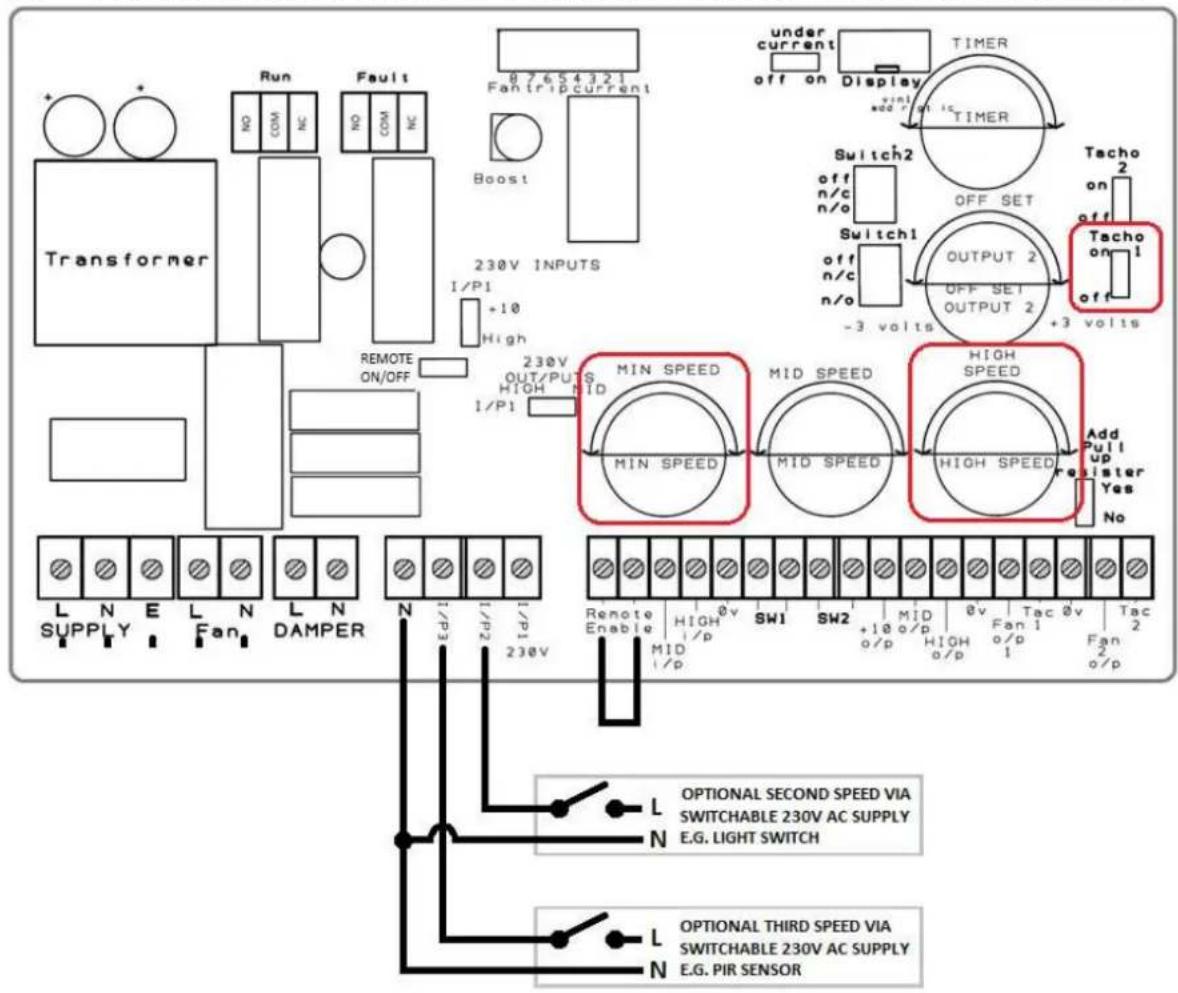
Trickle speed set-point (Min Speed)
The speed is defined by the 'Min speed' Potentiometer, by rotating the potentiometer dial it will change the set speed of the fan.
Optional second speed (Mid Speed)
The speed is defined by the 'Mid speed' Potentiometer, by rotating the potentiometer dial it will change the set speed of the fan.
Optional third speed (High Speed)
The speed is defined by the 'High speed' Potentiometer, by rotating the potentiometer dial it will change the set speed of the fan.
6.5. REMOTE ENABLE AND SPEED CONTROL VIA EXTERNAL REB-ECOWATT

PRIOR TO ENERGISING THE MULTI-REG, THE INSTALLER MUST SET ALL THREE OF THE SPEED POTENTIOMETERS TO THEIR MINIMUM (FULLY ANTI-CLOCKWISE) POSITION.
Fan speed
The speed is defined by rotating the dial on the REB-ECOWATT.
6.6.
REMOTE ENABLE AND SPEED CONTROL VIA EXTERNAL REB-CVF

PRIOR TO ENERGISING THE MULTI-REG, THE INSTALLER MUST SET ALL THREE OF THE SPEED POTENTIOMETERS TO THEIR MINIMUM (FULLY ANTI-CLOCKWISE) POSITION.
Fan speed
The speed is defined by rotating the dial on the REB-CVF.
6.7. CONTINUOUS RUNNING WITH TWO OPTIONAL SPEEDS VIA EXTERNAL SWITCHED 230V SUPPLY
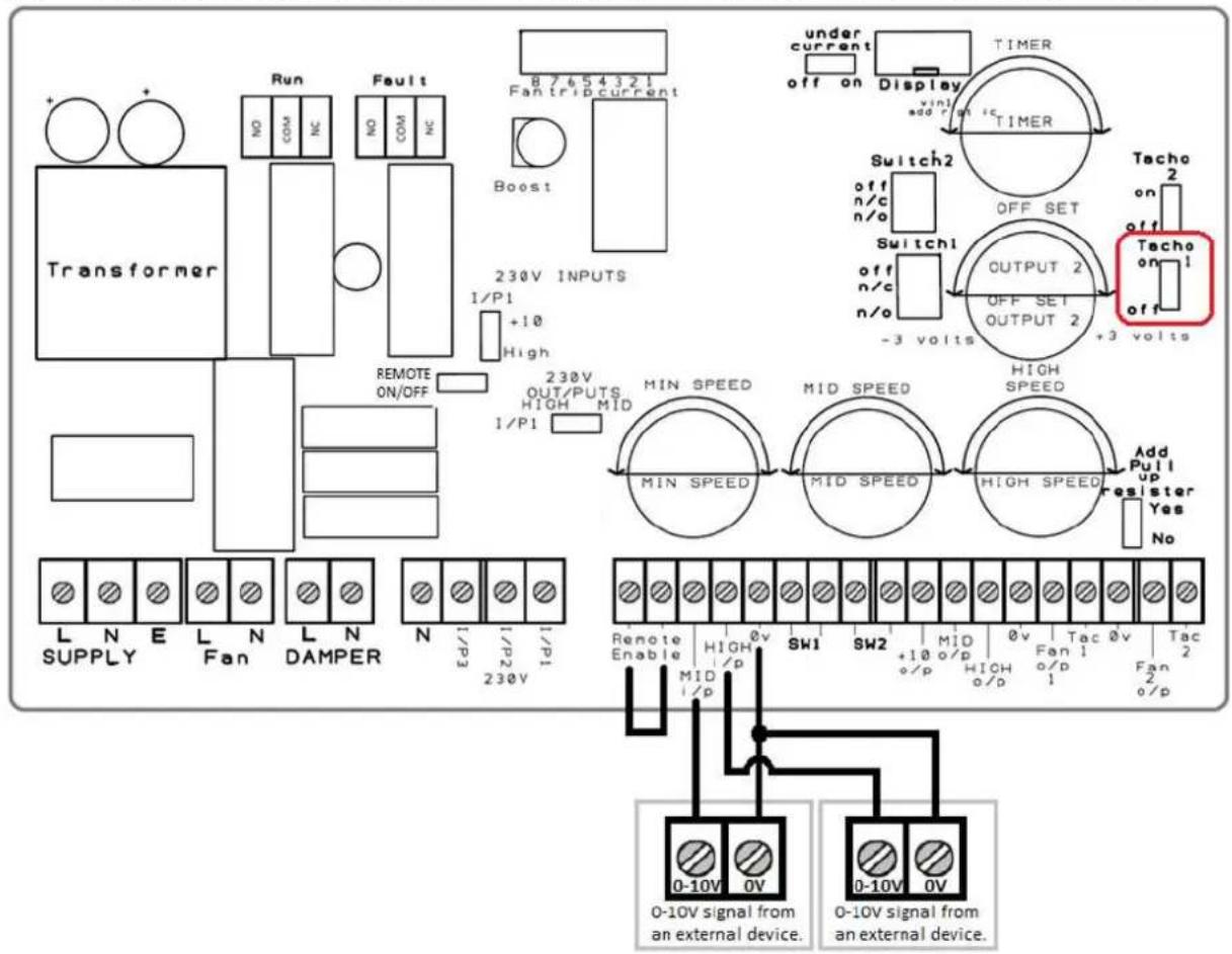
PRIOR TO ENERGISING THE MULTI-REG, THE INSTALLER MUST SET ALL THREE OF THE SPEED POTENTIOMETERS TO THEIR MINIMUM (FULLY ANTI-CLOCKWISE) POSITION.
Fan speed (0-10V)
The speed is defined by the highest voltage of the two 0 - 10V signals from the external devices; the minimum output is 3V.
6.8. REMOTE ENABLE VIA 7-DAY TIMER (1000001114)

Fan speed set-point (Min speed)
The speed is defined by the 'Min speed' Potentiometer, by rotating the potentiometer dial it will change the set speed of the fan.
6.9.
RUN AND FAULT RELAY

Run relay (Maximum current load 8A)
Fan Running – Continuity between COM and NO
Fan Stopped – Continuity between COM and NC
Fault relay (Maximum current load 8A)
Fan Running/Stopped – Continuity between COM and NC
Fault with Fan – Continuity between COM and NO
6.10. FAULT INPUTS

External fault switch (SW1)
When the fan is in normal running conditions the switch should be in the closed position. If additional switches are required then they can be connected in series. During start-up there is a 60 seconds delay to allow the airflow to increase. When the fault switch opens signifying loss of airflow, the controller will automatically stop the fan and display "EXTERNAL SW1 FAULT".
Following an "EXTERNAL SW1 FAULT", a manual re-start will be required.
External fire shut-off switch (SW2)
When the fan is in normal running conditions the switch should be in the closed position. When the fault switch opens signifying the fire alarm has been activated, the controller will automatically stop the fan and display "FIRE ALARM ACTIVATED".
Following a "FIRE ALARM ACTIVATED" notification, a manual re-start will be required
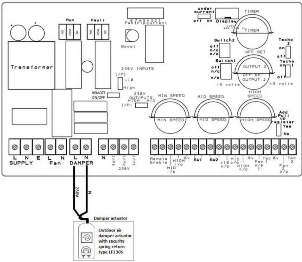
6.11. DAMPER
flowchart
graph TD
    A["Transformer"] --> B["Run"]
    A --> C["Fault"]
    A --> D["230V INPUTS"]
    A --> E["230V OUTPUT"]
    A --> F["MIN SPEED"]
    A --> G["MID SPEED"]
    A --> H["HIGH SPEED"]
    A --> I["Add Pull up Resister Yes No"]
    J["Damper actuator"] --> K["Outdoor air damper actuator with security spring return type LF230S"]
    L["Supply"] --> M["1/N E Fan"]
    M --> N["230V"]
    N --> O["230V OUT/PUTS HIGH MID 1/PI"]
    O --> P["230V OUT/PUTS HIGH MID 230V INPUTS 1/P1"]
    Q["External indicators"] --> R["Monitor: Remote Enable, Mid i/p, SW1, SW2, +10 o/p, +10 o/p, +10 o/p, Fan 1, Fan 2 o/p"]
    S["Monitor: Under current off on Display, TIMER, Switch2, Switch1, OUTPUT 2, OUTPUT 2, Tacho on Tacho on"]
    T["External indicators"] --> U["Monitor: Monitor: Display, TIMER, Switch2, Switch1, OUTPUT 2, OUTPUT 2, Tacho on Tacho on"]
    V["External indicators"] --> W["Monitor: Monitor: Monitor, Mid Speed, High Speed"]
    X["External indicators"] --> Y["Monitor: Monitor: Monitor, Mid Speed, High Speed"]
Damper actuator
When the fan is running, the damper opens. When the fan is stopped (intentionally or in a fault condition) the damper's spring return facility closes the damper.
6.12. OVER-RUN TIMER
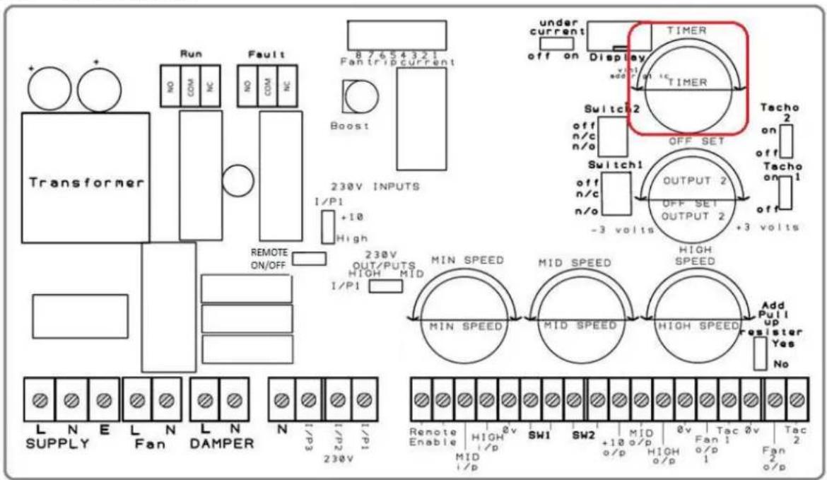
Operation:
The over-run timer works when you alter the 'Timer' potentiometer, this will allow you to add an over-run of 0 to 15 minutes; the over-run function will operate for both remote enable and boost functions.
If a 10 minute over-run is set then the remote enable will over-run for 10 minutes and the boost will over-run for 10 minutes.
6.13. FAN SPEED OFFSET

Operation:
The fan speed offset works when you alter the 'Off-set Output 2' potentiometer, this will allow you to alter the fan 2 output by +3V or -3V; this is limited by the minimum output 3V and maximum output 10V.
If a 7V supply is required by fan 1 and a 4V supply is required by fan 2 then you will alter the Off-set Output 2^ potentiometer anti-clockwise.
If a 7V supply is required by fan 1 and a 10V supply is required by fan 2 then you will alter the Offset Output 2' potentiometer clockwise.
7. MAINTENANCE
- Before handling the ventilator, make sure it is disconnected from the mains supply even if it has previously been switched off. Prevent the possibility of anyone else connecting it while it is being worked on.
- The apparatus must be regularly inspected. These inspections should be carried out bearing in mind the ventilator's working conditions, in order to avoid dirt or dust accumulating on the impeller, motor or back-draught shutter. This could be dangerous and perceptibly shorten the working life of the ventilator unit.
• While cleaning, great care should be taken not to unbalance the impeller or motor. - All maintenance and repair work should be carried out in strict compliance with each country's current safety regulations.
8. RECYCLING
- EEC Standards, together with the responsibility we should assume with future generations in mind, oblige us to recycle all the materials we can. Therefore, please deposit all left-over material and packaging in their corresponding recycling containers and hand in the replaced machines to the nearest handler of this type of waste product.
- If you have any queries about S&P products, please contact our after-sales service at your local S&P dealer. If in doubt, please visit our website at www.solerpalau.co.uk
9. EC DECLARATION OF CONFORMITY
- Herewith we declare that the fan/control designated below, on the basis of its design and construction in the form brought onto the market by us is, in accordance with the relevant EC Council Directives on Electromagnetic Compatibility. If alterations are made to the apparatus without prior consultations with us, this declaration becomes invalid. We further declare that the equipment identified below may be intended to be assembled with other equipment/machines to constitute machinery, which shall not be put into service until the assembled machinery has been declared in conformity with the provisions of these relevant EC Council Directives.
10. DESIGNATION OF EQUIPMENT
- Relevant EC Council Directives, Electromagnetic Compatibility Directive (89/336/EEC.) Applied Harmonised standards in particular BS EN 50081-1:1992, BS EN50082-1:1998, BS EN 61000-3-2: 1995, BS EN 61000-3-3:1995
11. GUARANTEE
S&P Limited Warranty
24 (TWENTY FOUR) MONTH PRODUCT WARRANTY
S&P UK Ventilation Systems Limited warrants that the MULTI-REG Control will be free from defective materials and workmanship for the period of 24 (twenty four) months from the date of original purchase. In the event that we find any part is defective the product will be repaired or at the company's discretion, replaced without charge provided that the product has been installed in accordance with the enclosed instructions and all applicable standards and national and local building standards.
IF CLAIMING UNDER WARRANTY
Please return the completed product, carriage paid, to your local authorized distributor. All returns must be accompanied by a valid Invoice of Sale. All returns must be clearly marked "Warranty Claim", with an accompanying description stating the nature of the fault.
THE FOLLOWING WARRANTIES DO NOT APPLY
- Damages resulting from improper wiring or installation.
- Damages resulting when using the fan/control with fans/motors/controls/sensors other than those supplied and manufactured by the S&P Group of Companies.
- Removal or alteration of the S&P data plate label.
WARRANTY VALIDATION
- The end user must keep a copy of the Invoice of Sale to verify a purchase date.

S&P UK VENTILATION SYSTEMS LTD
S&P HOUSE
WENTWORTH ROAD
RANSOMES EUROPARK
IPSWICH
SUFFOLK
TEL. 01473 276890
WWW.SOLERPALAU.CO.UK
CE EAC
REF. REV-3
Soler&Palau

Ventilation Group

- RECOMMENDATIONS
- TRANSPORT AND HANDLING
- GENERAL
- Speed Control Inputs
- Installer-defined Fixed Speed Control
- Remote Switching
- Fan-Fail Detection by Fault Sensing
- Outputs
- Analog Switch Outputs
- SAFETY RULES
- WARNING
- CAUTION
- SPECIFICATION
- INSTALLATION
- FAN WIRING
- CONTROL WIRING
- REMOTE ENABLE VIA EXTERNAL VOLT-FREE CONTACT
- CONTINUOUS RUNNING WITH TWO OPTIONAL SPEEDS VIA EXTERNAL VOLT-FREE CONTACTS
- CONTINUOUS RUNNING WITH TWO OPTIONAL SPEEDS VIA EXTERNAL SWITCHED 230V SUPPLY
- Trickle speed set-point (Min Speed)
- Optional second speed (Mid Speed)
- Optional third speed (High Speed)
- REMOTE ENABLE AND SPEED CONTROL VIA EXTERNAL REB-ECOWATT
- CONTINUOUS RUNNING WITH TWO OPTIONAL SPEEDS VIA EXTERNAL SWITCHED 230V SUPPLY
- PRIOR TO ENERGISING THE MULTI-REG, THE INSTALLER MUST SET ALL THREE OF THE SPEED POTENTIOMETERS TO THEIR MINIMUM (FULLY ANTI-CLOCKWISE) POSITION.
- FAULT INPUTS
- External fault switch (SW1)
- External fire shut-off switch (SW2)
- DAMPER
- Damper actuator
- OVER-RUN TIMER
- Operation:
- FAN SPEED OFFSET
- MAINTENANCE
- RECYCLING
- EC DECLARATION OF CONFORMITY
- DESIGNATION OF EQUIPMENT
- GUARANTEE
- IF CLAIMING UNDER WARRANTY
- THE FOLLOWING WARRANTIES DO NOT APPLY
- WARRANTY VALIDATION
Brand : Soler & Palau
Model : MULTI-REG CONTROL IP54
Category : Controller