
REB-ECOWATT - Controller Soler & Palau - Free user manual and instructions
Find the device manual for free REB-ECOWATT Soler & Palau in PDF.


| Product Type | Electronic speed controller for ventilation fans |
| Brand | Soler & Palau |
| Model | REB-ECOWATT |
| Dimensions (W x H x D) | 120 mm x 80 mm x 60 mm |
| Weight | 0.3 kg |
| Power Supply | 230 V AC, 50/60 Hz |
| Maximum Load Current | 2.5 A (resistive), 1.5 A (inductive) |
| Control Type | Stepless rotary knob |
| Output Voltage Range | 40-230 V AC (depending on load) |
| Protection Rating | IP20 |
| Operating Temperature | 0 °C to 40 °C |
| Storage Temperature | -10 °C to 60 °C |
| Housing Material | ABS plastic, flame retardant |
| Mounting | Wall-mount or flush-mount (with optional box) |
| Connection Terminals | Screw terminals for mains and fan |
| Indicators | Green LED for power, red LED for overload |
| Functions | Variable speed control, soft start, thermal overload protection |
| Maintenance | Wipe with dry cloth; no regular maintenance required |
| Safety | Double insulation, overcurrent protection |
| Spare Parts Available | Replacement knob, terminal covers |
| Repairability | Serviceable by qualified electrician; no user-serviceable parts |
Frequently Asked Questions - REB-ECOWATT Soler & Palau
User questions about REB-ECOWATT Soler & Palau
0 question about this device. Answer the ones you know or ask your own.
Ask a new question about this device
Download the instructions for your Controller in PDF format for free! Find your manual REB-ECOWATT - Soler & Palau and take your electronic device back in hand. On this page are published all the documents necessary for the use of your device. REB-ECOWATT by Soler & Palau.
USER MANUAL REB-ECOWATT Soler & Palau
Electronic single phase speed controllers. Available in wall box or flush mount versions. Fuse protected + spare fuse included. Minimum speed adjustment. Single ON/OFF and speed regulation control knob.

natural_image
Two white industrial electrical switch knobs with rotary dials, shown from different angles (no text or symbols visible)
| Model Electrical supply IP | Protection | Power (VA) | Maximum current (A) | Minimum current (A) | Class Operating temperature range (°C) | ||
| Frequency (Hz) | Voltage (V) | ||||||
| REB-1N/1NE | 50 220-240 IP44 | 220 1 0,15 | Class II | ||||
| REB-2,5N/2,5NE 550 2,5 0,15 | |||||||
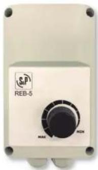
LxWxH (mm): 83 x 81 x 160
REB-5
Electronic single phase speed controller. Surface mounted. Fuse protected. Minimum speed adjustment. Separate ON/OFF switch.
| Model | Electrical supply | IP Protection | Power (VA) | Maximum current (A) | Class Operating temperature range (°C) | |
| Frequency (Hz) | Voltage (V) | |||||
| REB-5 | 50 | 230 | IP54 | 1150 | 5 | Class I +5 / +35 |

LxWxH (mm): 115 x 95 x 195
REB-10
Electronic single phase speed controller. Surface mounted. Fuse protected. Minimum speed adjustment. Separate ON/OFF switch.
| Model | Electrical supply | IP Protection | Power (VA) | Maximum current (A) | Class | Operating temperature range (°C) | |
| Frequency (Hz) | Voltage (V) | ||||||
| REB-10 | 50 | 230 | IP54 | 2300 | 10 | Class I | +5 / +35 |
natural_image
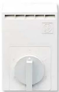
Close-up of a white electrical switch with a circular dial and indicator lights (no visible text or symbols)LxWxH (mm): 90 x 54 x 134
RRB-100
Electromechanical single-phase speed controller.
Variable reactance.
Surface mounted.
Five position knob.
| Model Electrical supply IP | Protection | Power (VA) | Maximum current (A) | Class Operating temperature range (°C) | |
| Frequency (Hz) | Voltage (V) | ||||
| RRB-100 50 230 | IP20 94,3W 0,41 | Class II 5-45°C | |||

natural_image
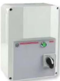
Front view of a light blue industrial control panel with a green indicator dial and 'RMB' label (no readable text beyond branding)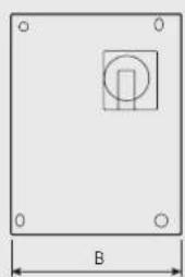
natural_image
Simple geometric diagram of a square with a central square and corner holes, labeled 'B' at the bottom (no text or symbols within the diagram itself)
RMB
Single phase speed controller by auto-transformer.
IP56 ABS casing.
Electrical supply: 1/230V/50-60Hz.
Five position knob (0/1/2/3/4).
Voltage: 80, 105, 130, 160 and 230 V.
Pilot light.
| Model Maximum current (A) | Casing IP Protection | Class Operating temperature range (°C) | Dimensions (mm) | Weight (kg) | ||||
| A B C | ||||||||
| RMB-1,5 | 1,5 | PP V0 | IP55 | Class I | 0 / +40 | 230 | 180 | 95 |
| RMB-3,5 | 3,5 | 230 | 180 | 95 | ||||
| RMB-5 | 5 | 230 | 180 | 95 | ||||
| RMB-8 | 8 | 310 | 230 | 125 | ||||
| RMB-10 | 10 | 310 | 230 | 1250 | ||||

natural_image
Exterior view of a beige industrial control box with buttons and a small label (no visible text or symbols)RMT configuration with metallic box
natural_image
Exterior view of a white industrial electrical control box with a rotary knob (no visible text or symbols)RMT configuration with ABS box
RMT
Three phase speed controller by auto-transformer.
IP54 ABS casing for RMT-1,5 and RMT-2,5 models.
IP54 metallic casing from RMT-5 to RMT-12 models.
Electrical supply: 3/400V/50-60Hz. Six position knob (0/1/2/3/4/5).
Voltage: 90, 150, 200, 280 and 400 V. Pilot light.

natural_image
Simple geometric diagram of a square plate with a central square and dimension label B (no text or symbols)
| Model | Maximum current (A) | Casing IP | Protection | Class | Operating temperature range (°C) | Dimensions Weight | (kg) | ||
| A B C | |||||||||
| RMT-1,5 | 1,5 | ABS | IP54 | Class I | 0 / +40 | 280 | 200 | 140 6 | |
| RMT-2,5 | 2,5 | ABS | 280 | 200 | 140 | 13 | |||
| RMT-5 | 5 | Metallic | 300 | 250 | 205 | 16 | |||
| RMT-8 | 8 | Metallic | 400 | 300 | 205 | 21 | |||
| RMT-12 | 12 | Metallic | 400 | 300 | 205 | 30 | |||

natural_image
White rectangular industrial control box with a rotary knob and indicator button (no visible text or symbols)REV
Auto-transformer.
Single phase 230V-50 Hz.
Wall mounting.
IP44.
Motor PTO connection.
Maximum switch output: (1A).

natural_image
Simple geometric diagram of a rectangular frame with a central square and corner holes, labeled 'B' at the bottom (no text or symbols within the diagram itself)
| Model Maximum | current(A) | Dimensions Weight | (kg) | ||
| A B C | |||||
| REV-1,6N 1,6 A 240 190 120 3 | |||||
| REV-3N 3 A 240 190 120 5 | |||||
| REV-5N 5 A 240 190 120 6 | |||||
| REV-7N 7 A 240 190 120 7 | |||||
| REV-10N 10 A 290 240 160 12 | |||||
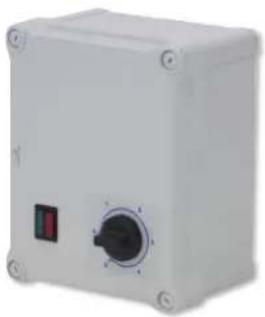
natural_image
Exterior view of a white industrial control box with a rotary knob and indicator lights (no text or symbols visible)RDV
Auto-transformer.
Three phase 400V-50 Hz.
Wall mounting.
IP44.
Motor PTO connection.
Maximum switch output: (1A).

natural_image
Simple geometric diagram of a square plate with a central square and side holes, labeled 'B' at the bottom (no text or symbols within the shape)
| Model Maximum | current(A) | Dimensions Weight | (kg) | ||
| A B C | |||||
| RDV-0,8N | 0,8 A 290 240 | 160 5,8 | |||
| RDV-1,2N | 1,2 A 290 240 | 160 8 | |||
| RDV-2,5N | 2,5 A 290 240 | 160 11,2 | |||
| RDV-3,2N | 3,2 A 290 240 | 160 14,7 | |||
| RDV-5N | 5 A 340 290 | 160 18,5 | |||
| RDV-7N | 7 A 340 290 | 160 21 | |||
| RDV-10N | 10 A 400 300 | 200 | 38 | ||

natural_image
White electrical circuit breaker with red and yellow color scheme, no visible text or symbolsLxWxH (mm): 85 x 90 x 120
PARO/MARCHA 5P and PARO/MARCHA 8P
ON/OFF Electrical isolation switch.
PARO/MARCHA 5P (ON/OFF 5P):
Five pole electrical isolation switch. One speed motor application (3 wires). Maximum absorbed current: 20A. Open / close position reset. IP66 / IP67 protection. 3x380V / 3x440V motors. 1x220-240V motors.
PARO/MARCHA 8P (ON/OFF 8P):
Eight pole electrical isolation switch. Two speed motor application (6 wires). Maximum absorbed current: 20A. Open / close position reset. IP55 protection. 3/380-440V motors.

natural_image
Close-up of a red circular switch with yellow base, mounted on a silver frame (no visible text or symbols)DESENFUMAGE SWITCHES
ON/OFF switches to work immersed at 400°C/2h. Aluminum enclosure. Maximum intensity allowed depending on Model, from 25A to 125A. To apply to 3x380V / 3x440V motors. Frequency: 50-60Hz. IP65.


Model A B
| Desenfumage switches | ||
| INT-IPM 25/6P-F300 | ||
| INT-IPM 25/6P-F400 | ||
| INT-IPM 40/6P-F400 | ||
| INT-IPM 63/6P-F400 | ||
| INT-IPM 125/6P-F400 | ||
| Desenfumage switches with auxiliary contactors | ||
| INT-IPM 25/6P+1NA+1NC-F300 | ||
| INT-IPM 25/6P+2AUX-F300 | ||
| INT-IPM 25/6P+2AUX-F400 | ||
| INT-IPM 40/6P+2AUX-F400 | ||
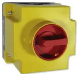
natural_image
Yellow industrial electrical switch component with red circular port (no visible text or symbols)INTZ
ON/OFF electrical isolation switch.
3 and 6 pole electrical isolation switch.
3-point lock.
Open / close position reset.
230V single-phase or 400V-50/60Hz
three-phase motor.
IP65 Protection Index: outdoor
installation if possible.
Supplied with cable.
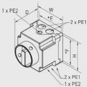
| Model Switch output main contacts (AC23) | W (mm) | H (mm) | D (mm) | E* (mm) | F* (mm) | PE1 PE2 |
| Confort Smoke extract** |
1 speed
| INTZ 1V15 15,4 A 10,2 A 90,5 90,5 102 80 80 M20 M12 | |||||
| INTZ 1V22 22,4 A 14,9 A 115 115 136 100 100 M25 M16 | |||||
| INTZ 1V29 29,8 A 19,8 A 115 115 136 100 100 M25 M16 | |||||
| INTZ 1V43 43 A 28,6 A 145 145 158 130 130 M25/32/40 M20 | |||||
| INTZ 1V68 68 A 45,3 A 167 220 144 151 203 M25/32/40 M20 | |||||
| 2 speed | |||||
| INTZ 2V15 15,4 A 10,2 A 90,5 90,5 139 80 80 M20 M12 | |||||
| INTZ 2V22 22,4 A 14,9 A 115 115 163 100 100 M25 M16 | |||||
| INTZ 2V29 29,8 A 19,8 A 115 115 163 100 100 M25 M16 | |||||
| INTZ 2V43 43 A 28,6 A 145 145 188 130 130 M25/32/40 M20 | |||||
| INTZ 2V68 68 A 45,3 A 216 267 170 190 242 M40/50 M20 | |||||
* Mounting dimensions.
** Accordance with the regulations: smoke extract size = size confort/1.5.
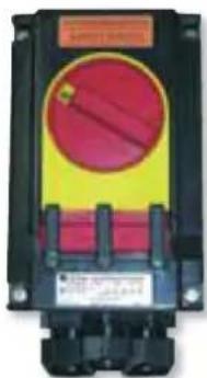
natural_image
Electrical control box with red and yellow casing (no visible text or symbols)INTZ ATEX
ON/OFF electrical isolation switch.
3 and 6 pole electrical isolation switch.
Electrical supply:
Single phase 230V-50/60Hz.
Three phase 400V-50/60Hz.
IP66.


| Model | A B C G H ∅ | ||||
| INTZ 02.10 ATEX 84 | 135 112 68,5 61,5 5,5 | ||||
| INTZ 02.20 ATEX 110 | 208 141 96 150 7 | ||||
| INTZ 02.40 ATEX | 140 270 168 126 197 7 | ||||
| INTZ 04.20 ATEX | |||||
| INTZ 04.40 ATEX 271 | 316 275 247 247 7 |
| Model | Maximum current (A) | Weight (kg) |
| 3 pole, 1 speed | ||
| INTZ 02.10 ATEX 10 0,55 | ||
| INTZ 02.20 ATEX 20 1,48 | ||
| INTZ 02.40 ATEX 40 2,75 | ||
| 6 pole, 2 speed | ||
| INTZ 04.20 ATEX 20 | 2,43 | |
| INTZ 04.40 ATEX 40 | 6,5 | |

natural_image
White electrical circuit breaker with a red and black indicator light (no visible text or symbols)MSD
Motor starter for single and three phase motors with integrated termal contacts.
- Surface mounting.
- Cabinet installation.
- Potential free contact.
- IP 54.

| Model | Supply | Operating range |
| MSD | 3 - 400 V | Max. 25 A |
natural_image
Close-up of a white electrical switch with a black rotary dial and indicator lights (no visible text or symbols)LxWxH (mm): 85 x 90 x 120
COM D/S
Three phase fan Y / Δ switch.
Rotary switch with three positions, OFF, Y and .
Maximum absorbed current: 20A.
IP67 protection.
| Supply voltage Voltage of motor | |
| 380-400 V | III / 380 / 50 |
| III / 400 / 50 | |
| 220-230 V | III / 220-380 / 50 |
| III / 230-400 / 50 |

natural_image
Two industrial electrical switch components, one blue and one gray, with no visible text or symbols on the switches themselves.
MSK-EX
Set comprising a protection relay in
combination with a circuit breaker.
- For 400 V three-phase motors with PTC.
- Maximum current: 25 A.
- Mounting: (mount to the outside of the Atex zone).
MSD-2: IP54.
MS 220 KA: DIN rail mounting IP20.
| Model W H D | |||
| MSD-2 92 122 112 | |||
| MS 220 KA 23 76 116 |

natural_image
White industrial control panel with two side connectors and a valve (no visible text or symbols)APG-130
IP54 surface mounting box for MS 220 KA.
| Model IP Protection Dimensions (mm) | |
| APG-130 IP54 | 115x115x135 |
natural_image
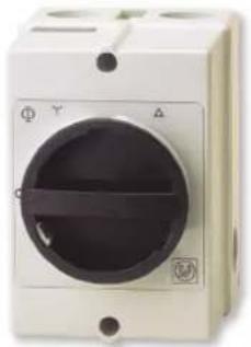
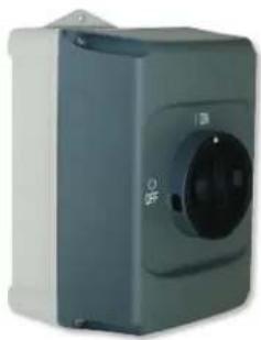
Exterior view of a gray industrial control unit with a circular dial and indicator lights (no visible text or symbols)DIJZ

Switch for 1-speed motor single or three phase. Thermal-magnetic circuit breaker and ON/OFF control for single speed motor.
- Unit Protection Indication = 0.25 to 32 A: IP65 and 40 to 63 A: IP 54.
- ON/OFF padlockable rotary switch.
- Auxiliary contact O / C.
- Outdoor installation possible.

DIJZ 05 0,25 to 25
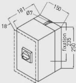
DIJZ 05 32 to 50
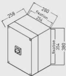
DIJZ 05 63
| Model Current Range (A) | |
| High speed | |
| DIJZ 05 0,25 0,16 to 0,25 | |
| DIJZ 05 0,4 0,25 to 0,4 | |
| DIJZ 05 0,63 0,4 to 0,63 | |
| DIJZ 05 1,0 0,63 to 1 | |
| DIJZ 05 1,6 1 to 1,6 | |
| DIJZ 05 2,5 1,6 to 2,5 | |
| DIJZ 05 4,0 2,5 to 4 | |
| DIJZ 05 6,3 4 to 6,3 | |
| DIJZ 05 10,0 6,3 to 10 | |
| DIJZ 05 16,0 10 to 16 | |
| DIJZ 05 20,0 16 to 20 | |
| DIJZ 05 25,0 20 to 25 | |
| DIJZ 05 32,0 25 to 32 | |
| DIJZ 05 40,0 28 to 40 | |
| DIJZ 05 50,0 40 to 50 | |
| DIJZ 05 63,0 45 to 63 | |
natural_image
White rectangular industrial enclosure with a small black button on the side (no visible text or symbols)DEMZ

DEMZ BI
Switch for 2-speed motors with independent windings.
DEMZ DA
Switch for 2-speed motors with Dahlander.


| Model | Current range (A) | |
| Low speed High speed | ||
| DEMZ 0,55/1,3 BI 0,41 to 0,55 1 to 1,3 | ||
| DEMZ 0,74/1,3 BI 0,55 to 0,74 1 to 1,3 | ||
| DEMZ 1/1,7 BI | 0,74 to 1 | 1,3 to 1,7 |
| DEMZ 1/2,3 BI | 0,74 to 1 | 1,7 to 2,3 |
| DEMZ 1,3/1,7 BI | 1 to 1,3 | 1,3 to 1,7 |
| DEMZ 1,3/2,3 BI | 1 to 1,3 | 1,7 to 2,3 |
| DEMZ 1,3/3,1 BI | 1 to 1,3 | 2,3 to 3,1 |
| DEMZ 1,7/2,3 BI | 1,3 to 1,7 | 1,7 to 2,3 |
| DEMZ 1,7/3,1 BI | 1,3 to 1,7 | 2,3 to 3,1 |
| DEMZ 1,7/4,2 BI | 1,3 to 1,7 | 3,1 to 4,2 |
| DEMZ 2,3/3,1 BI | 1,7 to 2,3 | 2,3 to 3,1 |
| DEMZ 3,1/4,2 BI | 2,3 to 3,1 | 3,1 to 4,2 |
| DEMZ 3,1/5,7 BI | 2,3 to 3,1 | 4,2 to 5,7 |
| DEMZ 3,1/7,6 BI | 2,3 to 3,1 | 5,7 to 7,6 |
| DEMZ 4,2/5,7 BI | 3,1 to 4,2 | 4,2 to 5,7 |
| DEMZ 4,2/7,6 BI | 3,1 to 4,2 | 5,7 to 7,6 |
| DEMZ 4,2/10 BI | 3,1 to 4,2 | 7,6 to 10 |
| DEMZ 5,7/7,6 BI | 4,2 to 5,7 | 5,7 to 7,6 |
| DEMZ 5,7/10 BI | 4,2 to 5,7 | 7,6 to 10 |
| DEMZ 5,7/13 BI | 4,2 to 5,7 | 10 to 13 |
| DEMZ 7,6/13 BI | 5,7 to 7,6 | 10 to 13 |
| DEMZ 7,6/15,5 BI | 5,7 to 7,6 13 to 15,5 | |
| DEMZ 10/13 BI | 7,6 to 10 | 10 to 13 |
| DEMZ 10/20 BI | 7,6 to 10 | 16 to 20 |
| DEMZ 10/24 BI | 7,6 to 10 | 20 to 24 |
| DEMZ 13/15,5 BI | 10 to 13 | 13 to 15,5 |
| DEMZ 13/29 BI | 10 to 13 | 24 to 29 |
| DEMZ 20/24 BI | 16 to 20 | 20 to 24 |
- IP 55 Enclosure.
-
0/LS/HS Rotary switch.
-
Thermal protection integrated.
- Auxiliary contact for gas solenoid valve.
- Outdoor installation possible.
| Model | Current range (A) | |
| Low speed High speed | ||
| DEMZ 0,55/1 DA | 0,41 to 0,55 | 0,74 to 1 |
| DEMZ 0,74/1,7 DA | 0,55 to 0,74 | 1,3 to 1,7 |
| DEMZ 0,74/2,3 DA | 0,55 to 0,74 | 1,7 to 2,3 |
| DEMZ 1/1,3 DA | 0,74 to 1 | 1 to 1,3 |
| DEMZ 1/1,7 DA | 0,74 to 1 | 1,3 to 1,7 |
| DEMZ 1/2,3 DA | 0,74 to 1 | 1,7 to 2,3 |
| DEMZ 1/3,1 DA | 0,74 to 1 | 2,3 to 3,1 |
| DEMZ 1,3/3,1 DA | 1 to 1,3 | 2,3 to 3,1 |
| DEMZ 1,3/4,2 DA | 1 to 1,3 | 3,1 to 4,2 |
| DEMZ 1,7/5,7 DA | 1,3 to 1,7 | 4,2 o 5,7 |
| DEMZ 2,3/5,7 DA | 1,7 to 2,3 | 4,2 to 5,7 |
| DEMZ 2,3/7,6 DA | 1,7 to 2,3 | 5,7 to 7,6 |
| DEMZ 2,3/10 DA | 1,7 to 2,3 | 7,6 to 10 |
| DEMZ 3,1/7,6 DA | 2,3 to 3,1 | 5,7 to 7,6 |
| DEMZ 3,1/10 DA | 2,3 to 3,1 | 7,6 to 10 |
| DEMZ 4,2/10 DA | 3,1 to 4,2 | 7,6 to 10 |
| DEMZ 4,2/13 DA | 3,1 to 4,2 | 10 to 13 |
| DEMZ 5,7/13 DA | 4,2 to 5,7 | 10 to 13 |
| DEMZ 5,7/15,5 DA | 4,2 to 5,7 | 13 to 15,5 |
| DEMZ 5,7/24 DA | 4,2 to 5,7 | 20 to 24 |
| DEMZ 7,6/24 DA | 5,7 to 7,6 | 20 to 24 |
| DEMZ 10/20 DA | 7,6 to 10 | 16 to 20 |
| DEMZ 10/29 DA | 7,6 to 10 | 24 to 29 |

natural_image
White wall-mounted electrical switch with two buttons (one open, one closed) and a plus/minus signs, no visible text or symbols.LxWxH (mm): 80 x 45 x 80
REGUL-2
Fan ON/OFF and speed selector
I/II switch.
Maximum absorbed current: 4.5A.
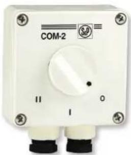
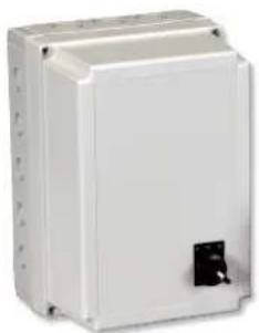
natural_image
White industrial control box labeled COM-2 with black connectors and a dial (no readable text beyond branding)LxWxH (mm): 84 x 37 x 81
COM-2
Two speed switch.
Fan ON/OFF and speed selector I/II rotary switch.
Maximum current rating 4A.
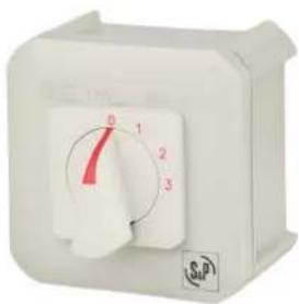
natural_image
White industrial control switch with three rotary dial (0, 1, 2, 3) and a red pointer, no visible text or symbols beyond dial indicators.LxWxH (mm): 90 x 90 x 75
COM-3
Three-speed switch
Fan ON/OFF and speed selector Maximum current rating 4A.

natural_image
White rectangular electrical switch with a rotary knob (no visible text or symbols)LxWxH [mm]: 86 x 86 x 60,4
INTER 4P
Three speed switch.
Fan ON/OFF and speed selector Maximum current rating 4A.

natural_image
Simple diagram with a rectangle containing two symbols: an 'x' inside and a cross inside, no text or labels present.LxA (mm): 80 x 75
INTERRUPTOR VMC 2V
Two speed switch.
Normal / Boost switch (No 'OFF') suitable for use with whole house extract units.

natural_image
Close-up of a metallic pressure gauge with dial and connector (no visible text or symbols)LxWxH (mm): 110 x 57 x 80
PRESOSTATO DPS
Differential pressure switch to control the fan running and the filter clogging up.
Protection class: IP54.
Can be used outside.
Model ΔP
PRESOSTATO DPS 2-30 20 - 300 Pa
PRESOSTATO DPS 10-100 100 - 1000 Pa
PRESOSTATO DPS 100-500 1000 - 5000 Pa
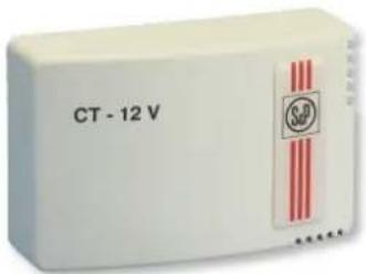
LxWxH (mm): 130 x 43 x 82
CT-12/14 and CT-12/14R
Safety isolating transformer
230V/12V - 50Hz.
Fuse protection.
CT-12/14R: incorporates adjustable timer
(1-30 minutes).
| Electrical supply Output | voltage(V) | IPprotection | Class Maximum | ||
| Frequency(Hz) | Supply voltage(V) | power(V.A.) | |||
| 50 220-240 | 12 IP21 Class II 14 | ||||

LxWxH (mm): 130 x 43 x 82
HIG-2
Humidistat.
Enables the automatic ON/OFF operation of an extract fan by monitoring the relative humidity level.
Adjustable pre-set RH level 60-90%. Incorporates timer.
| IP Protection | Class Maximum current (A) | Operating temperature | Humidity adjustment |
| IP21 Class II *6 (2)** 0-40 °C 60-90% | |||
* For resistant loads
** For inductive loads

LxWxH [mm]: 130 x 43 x 82
SQA
Air quality sensor.
Automatically switches the fan on when the quality of the ambient air deteriorates below an acceptable level due to fumes, odours, tobacco, smoke or dampness, etc. Adjustable run-on-timer facility which enables the fan to operate for a pre-selected time period after the air quality sensor has switched off.
Important: this sensor must not be used to detect combustible gases or fires and in connection with any safety alarm systems.
| IP Protection | Class Maximum | Operating temperature | Timing | |
| current (A) | ||||
| IP21 | Class II | *6 (2)** 0-50 °C | 1-25 min. | |
* For resistant loads
** For inductive loads
natural_image
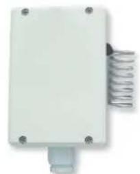
White rectangular electronic device with a coiled spring attached (no visible text or symbols)LxWxH (mm): 86 x 80 x 50
THE 16/4 A
Surface-mounted adjustable thermostat.
- 230V-50Hz.
- IP54. Can be installed outdoors.
- Maximum current: 4A (inductive).
- Temperature range: 0°C to +40°C.
- Differential: ± 0.75 K.

natural_image
Blue electronic device with coiled copper wires, no visible text or symbolsLxWxH (mm): 85 x 125 x 58
THE-F thermostat with capillary tube anti-frost sensor
Thermostat with capillary tube sensor to prevent the risk for freezing.
- IP30.
- Contact capacity: 16A to 1-230V-50Hz.
- Temperature range: -18°C to +13°C.
- Includes mounting support, channel and set of 3m long capillary tubes.

natural_image
Pure electrical circuit lines without any symbolsLxWxH (mm): 32 x 10 x 20
TIMER ZN 62
Timer habitat range products.
Starting up: 1 min.
Timing: 6 min.
Resistive load - 2.5 A
Inductive load - 1.6 A

natural_image
White rectangular device with a circular dial indicator on the left side (no visible text or symbols)LxWxH (mm): 83 x 40 x 153
PULSER
Single phase electric heater controller. Electronic controller to regulate the heat output of electric heater in order to maintain a constant pre-selected temperature. Depending on the selected temperature, the controller pulses the entire power output and uses a time-proportional control to maintain that temperature.
| Electrical supply IP | Protection | Voltage (V) | Minimum Maximum Operating | temperature | Thermostat adjustment (airtemp) | ||||
| Frequency (Hz) | Supply voltage (V) | Current (A) | Power (W) | Current (A) | Power (W) | ||||
| 50-60 220-415 IP30 | 230 V - I 1 230 16 3680 | 0-50°C 0-30°C | |||||||
| 400 V - III 1 400 16 6400 | |||||||||

natural_image
Blank white rectangular object with a small circular dial on the right side (no text or symbols visible)LxWxH (mm): 83 x 40 x 153
PULSER-ADD
Single phase electric heater controller. Supplementary unit for slave control from another PULSER to control electric heaters with power ratings high to the PULSER capacity (3600W-230V).

natural_image
Blank white rectangular object with a small circular icon in the bottom right corner (no text or symbols visible)LxWxH (mm): 83 x 40 x 153
PULSER-M
Single phase electric heater controller. Set point: 0-30°C, the sensor determines the scale range (for use with NTC-sensor). Output (load): 16 A (min. 1 A). Protection class: IP30. Input regulation maximum and minimum. Maximum absorbed power: 3.6 kW.
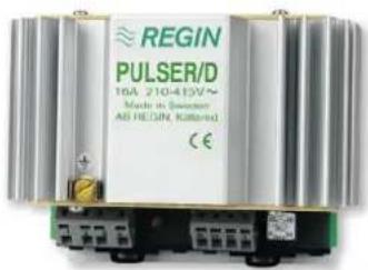
LxWxH (mm): 115 x 59 x 88
PULSER-D
Single phase electric heater controller. Similar controller to the PULSER designed to be fitted in a cabinet on DIN-rail (IP20). Set point: 0-30°C, the sensor determines the scale range (for use with NTC-sensor). Output (load): 16 A (min. 1 A). Maximum absorbed power: 3.6 kW.

LxWxH (mm): 160 x 140 x 280
TTC-2000
Three phase electric heater controller. Electronic controller to regulate the heat output for three phase electric heater in order to maintain a constant pre-selected temperature. Depending on the selected temperature, the controller pulses the entire power output and uses a time-proportional control to maintain that temperature.
Control signal: 0-10 V (external signal).
| Frequency (Hz) | Electrical supply Voltage | (V) | Minimum Maximum Operating | temperature | Thermostat adjustment (airtemp) | ||||
| Supply voltage (V) | IP Protection | Current (A) | Power (W) | Current (A) | Power (W) | ||||
| 50-60 380-415 IP30 | 230 V | 3 1,5 25 | 17 0-50°C | 0-30°C | |||||
| 400 V | |||||||||

natural_image
Green printed circuit board with two white connectors and a beige terminal block (no visible text or symbols)LxWxH (mm): 60 x 30 x 35
TT-S1
Additional PCB to increase the output power controlled.
The load connected to TT-S1 should be of equal size to the load connected to the TTC2000.
TTC2000 detects if a TT-S1 is installed and automatically adapts the control function accordingly.
natural_image
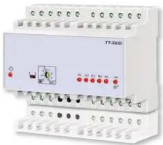
Exterior view of a TT-560D industrial control unit with indicator lights and wiring (no readable text or symbols beyond branding)LxWxH (mm): 101 x 85 x 74
TT-S6/D
TT-S6/D is a step controller designed to control electric heaters. It can also be used to control cooling processes.
Control signal: 0-10Vdc from a TTC40F, TTC25, TTC80F or other type of regulator with a 0-10Vdc output signal.
Protection class IP20.

LxWxH (mm): 195 x 95 x 220
TTC-25 and TTC-40F
Three-phase electric heater controller. Electronic controllers to regulate the heat output for three phase electric heaters and controllers in order to maintain a constant pre-selected temperature. Depending on the selected temperature, the controllers pulse the entire power output and uses a time-proportional control to maintain that temperature. The TTC-25 and 40F are designed to be fitted in a cabinet on DIN-rail. Supply voltage: three phase 210-415 V.
- Output: TTC25: 25 A, 400 V, 17 kW. TTC40: 40 A, 400 V, 27 kW.
Set point: 0-30°C (sensor determines the scale range).
Sensor inputs: Two (2), main- and max, min. limit sensors.
Control signal: 0-10 V.
Protection class: IP20.

natural_image
Plain white rectangular electronic device with black ventilation slots (no text or symbols visible)LxWxH (mm): 70 x 30 x 70
TG-R
Used in conjunction with electric heaters and controllers.
NTC type with liner scale. Range of temperature 0-30°C.
Protection class IP30.
2 models:
- Room sensor with set point adjustment, 0-30°C (TG-R430).
- Room sensor without set point adjustment, 0-30°C (TG-R530).

natural_image
Cylindrical coiled wire with a metal rod extending from its end, against a plain white background (no text or symbols visible)TG-K
Duct temperature sensor.
Used in conjunction with electric heater and controller.
NTC type with liner scale.
Protection class IP20.
Models:
- TG-K330: from 0 to 30°C.
- TG-K360: from 0 to 60°C.
- TG-K310: from -20 to 10°C.

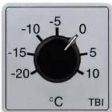

LxWxH (mm): 60 x 38 x 60
TBI
External potentiometer.
TBI-10
Potentiometer mounted on the main board panel for setting temperature between -20 and +10°C.
Used with the controller and a TG-K310 duct sensor to set the minimum air temperature beforeentering in the heat exchanger.
TBI-30
Potentiometer mounted on the main board panel for setting temperature between 0 and +30°C.
Used with the controller and with a TG-K330 duct sensor to set the air temperature after the electric heater in post heating operation.

MCR-1
Timer with set point between 1 second and 100 hours.
Used in an electric heating system to delay the fan switch off after disconnecting the system.

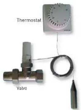
Thermostat
With 5 temperature control positions (12°C, 16°C, 20°C, 24°C, 28°C) and anti-frost protection which opens the valve automatically whenever the indoor temperature falls below 6°C.
The temperature control unit for MBW 100-200
The temperature control unit for MBW 100-200 hot water coil comprises a thermostat with a capillary tube sensor and a 2-way valve.
- 3/4" thermostatic valve
- Material: brass
- Surface: nickel plated
- Kv value: 0.65
- Kvs value: 0.90
- Size: DN 20
- Finish: Straight valve
- Max. diff. pressure: 1 bar
- Max. operating pressure: PN 10
- Max. temperature: 120 °C
- Thermostat unit 7-28 C 0 * 1-5, remote sensor and control, 5m
- Connection: M30 x 1.5

TRW control unit valve setting
The default factory setting for the valve is position 6.
Installation diagram

flowchart
graph LR
    A["Fresh air"] --> B["CAR Shutter"]
    B --> C["MFL Filtration box"]
    C --> D["In-line fan"]
    D --> E["MBW Hot water coil"]
    E --> F["Capillary tube sensor"]
    F --> G["Supply air"]
    H["TRW Temperature control unit"] --> I["2-way valve"]
    I --> J["Remote control thermostat"]
    J --> K["Antifrost protector with capillary tube"]
    style A fill:#90EE90,stroke:#333
    style B fill:#FFD700,stroke:#333
    style C fill:#E6F1F4,stroke:#333
    style D fill:#E6F1F4,stroke:#333
    style E fill:#E6F1F4,stroke:#333
    style F fill:#E6F1F4,stroke:#333
    style G fill:#FFA500,stroke:#333
    style H fill:#FFA500,stroke:#333
    style I fill:#FFA500,stroke:#333
    style J fill:#FFA500,stroke:#333
    style K fill:#FFA500,stroke:#333
natural_image
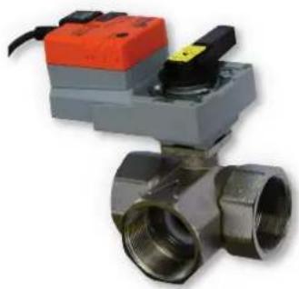
Close-up of a metallic T-joint valve with orange and gray components (no visible text or symbols)3WV 3P
3WV PROP
3-way motorized valves (CCV) with
3-point actuator.
Maximum pressure 16 bar.
Internal thread Rp"
Forged brass and nickel-plated casing.
Stainless steel valve cone.
Stainless steel shaft.
Water temperatures -10 to +120°C.
5Nm mounted rotary actuator.
AC 230V 3 points on-off.
90s/90° response time.
IP54.
3-way motorized valves (CCV) with
proportional actuator.
Maximum pressure 16 bar.
Internal thread Rp".
Forged brass and nickel-plated casing.
Stainless steel valve cone.
Stainless steel shaft.
Water temperatures -10 to +120°C.
5Nm mounted rotary actuator.
AC/DC 24V Proportional.
90s/90° response time
DC 2...10V analogue input range.
IP54.
Valve dimensioning diagram

line
| ΔpV100 [kPa] | V100 [m³/h] (DN-ks) | V100 [l/s] | | ------------ | ------------------- | ---------- | | 1 | 0.1 | 0.03 | | 2 | 0.2 | 0.06 | | 3 | 0.3 | 0.09 | | 4 | 0.4 | 0.12 | | 5 | 0.5 | 0.15 | | 6 | 0.6 | 0.18 | | 7 | 0.7 | 0.21 | | 8 | 0.8 | 0.24 | | 10 | 1 | 0.28 | | 20 | 2 | 0.56 | | 30 | 3 | 0.83 | | 40 | 4 | 1.1 | | 50 | 5 | 1.4 | | 60 | 6 | 1.7 | | 70 | 7 | 2.2 | | 80 | 8 | 2.8 | | 100 | 9 | 56 | | 200 | 10 | 8.3 | | 300 | 11 | 11 | | 400 | 12 | 14 | | 500 | 13 | 17 | | 600 | 14 | 22 | | 700 | 15 | 28 | | 800 | 16 | 56 | | 1000 | 17 | 8.3 |p_v100 : Differential pressure with valve fully opened
V_100 : Nominal flow at p_v100
Connection Diagram

flowchart
graph TD
    A["Water Coil"] --> B["Valve B"]
    B --> C["Motor M"]
    C --> D["Valve A"]
    D --> E["Return Line"]
    F["Return Line"] --> G["Return Line"]
    H["Return Line"] --> I["Return Line"]
    J["Return Line"] --> K["Return Line"]
    L["Return Line"] --> M["Return Line"]
Model
Motorized 3-way valves with 3-point actuator
3-way motorized valves with proportional actuator
3WV DN15 KVS1 PROP 24V
3WV DN15 KVS1,6 PROP 24V
3WV DN15 KVS2,5 PROP 24V
3WV DN20 KVS4 PROP 24V

natural_image
Close-up of a white appliance control panel with indicator lights and a rotary dial (no readable text or symbols)WCT
Proportional thermostat for control of 3-way-valves. Includes an air temperature sensor to be placed into duct.

natural_image
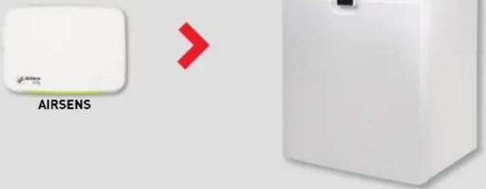
White rectangular electronic device with 'AIRSENS CO2' branding on the front face (no other text or symbols visible)AIRSENS
Intelligent sensor available in different reading models (CO2, VOC, RH and temperature).
Designed to create direct demand control ventilation systems without the need to install an intermediate control. AirSens can be linked with AC, ECOWATT (EC) fans or VFTM frequency drive. WiFi version also facilitates remote monitoring through S&P CONNECTAIR® platform.
Main features:
- 4 working modes:
- Relay output.
- 0-10V output.
- 2-10V output.
- Total control through Modbus or S&P CONNECTAIR® platform (WiFi version).
- Adjustable set point.
- IAQ level indicator (3-LED light diffuser).
- Adjustable 3-LED light diffuser intensity (OFF-100%).
All-in-one:
Reduces components, simplifies installation, increases savings.


flowchart
graph TD
    A["Conventional sensor Control Fan"] --> B["AIRSENS"]
    B --> C["Fan"]
The front LED indicator lets you know at any moment the IAQ level of the air.


natural_image
Interior view of a modern office with glass doors, featuring desks, chairs, and computers (no visible text or signage)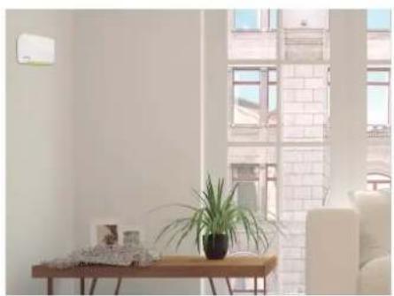
natural_image
Interior living room scene with a wooden table, potted plant, and large windows overlooking a brick building (no visible text or symbols)The new AirSens range offers a minimalist design patented by S&P so it can easily integrate into different ambients.
Recommendations of use
| Use COMMERCIAL / SERVICES SECTOR RESIDENTIAL | ||||||||||
| Office Meeting | Restaurant Shop Gym Classrooms Technical | areas | Kitchen Living | Bedroom Bathroom | ||||||
| room | room | |||||||||
| AIRSENS IAQ | ● | ● | ● | ● | ● | ● | ● | ● | ||
| AIRSENS CO2 | ● | ● | ● | ● | ● | ● | ● | |||
| AIRSENS VOC | ● | ● | ● | ● | ● | ● | ● | ● | ||
| AIRSENS RH | ● | ● | ● | |||||||
| AIRSENS TEMP | ● | ● | ||||||||
Good
Excellent
Standard version
| Model Electrical | supply | Power (W) | Relay output | Analog | Lecture range IP | protection | Dimensions LxAxH (mm) |
| AIRSENS CO2 | 100-240 VAC 50/60Hz | 0,7W | 3A 250 VAC | 0-10 V 2-10 V | 450-2000 ppm [NDIR technology] | IP30 122x23x89 | |
| AIRSENS VOC | 450-2000 ppm equivalent relative to CO_2 [CMOS technology] | ||||||
| AIRSENS RH 45-100% | |||||||
| AIRSENS TEMP 0-50°C |
Communication with ventilation unit
Standard version: wiring between AIRSENS and fan.

RF version
Wireless radio frequency communication (868.3MHz) between the AIRSENS RF transmitter and the REC. AIRSENS RF receiver. Each receiver can receive up to 4 signals simultaneously allowing the control of the indoor air quality in different rooms.
| Model Electrical | supply | Power (W) | Relay output | Analog | Lecture range IP | protection | Dimensions LxAxH (mm) |
| AIRSENS RF CO2 | 100-240 VAC 50/60Hz | 0.7W | 3A 250 VAC | 0-10 V 2-10 V | 450-2000 ppm [NDIR technology] | IP30 | 122x23x89 |
| AIRSENS RF VOC | 450-2000 ppm equivalent relative to CO2 (CMOS technology) | ||||||
| AIRSENS RF RH 45-100% | |||||||
| AIRSENS RF TEMP 0-50°C | |||||||
| REC.AIRSENS RF | Up to 4 signals from AIRSENS RF units | 135x31x77 |
Communication with ventilation unit
RF version: no cables between AIRSENS RF transmitter and REC.AIRSENS RF receiver. Final wiring between receiver and fan.


natural_image
White rectangular electronic device with two circular ports and a Wi-Fi symbol above it (no text or labels)
WIFI version
IAQ remote monitorization through WiFi communication (2,4GHz) and S&P CONNECTAIR platform. All models include relative humidity and temperature reading. Ventilation unit control through relay output or analogic (0-10V/2-10V).
| Model Electrical | supply | Power (W) | Relay Analog output | Lectures Lecture range IP | protection | Dimensions LxAxH (mm) | ||
| AIRSENS WIFI IAQ | 100-240 VAC 50/60Hz | 0,7W | 3A 250 VAC | 0-10 V 2-10 V | CO2/VOC/RH/T | CO2: 450-2000ppm (NDIR technology)VOC: 450-2000 ppm equivalent relative to CO,[CMOS technology]RH: 45-100%T: 0-50°C | IP30 122x23x89 | |
| AIRSENS WIFI CO2 | CO2/RH/T | |||||||
| AIRSENS WIFI VOC | VOC/RH/T | |||||||
| AIRSENS WIFI RH | RH/T | |||||||
Communication with ventilation unit
WIFI version: no cables between AIRSENS WIFI and mobile monitoring device.

flowchart
graph LR
    A["Connectair®"] -->|③| B["AIRSENS WIFI"]
    B --> C["Mobile monitoring device"]
    C --> D["VENTILATION UNIT"]

Connectair
The platform that allows you to control and manage your ventilation system

AIRSENS WIFI CO2

AIRSENS WIFI VOC
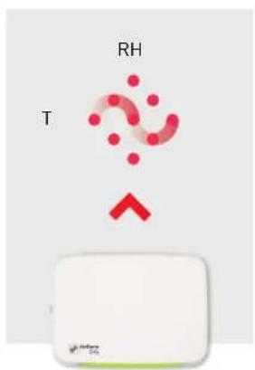
AIRSENS WIFI RH


natural_image
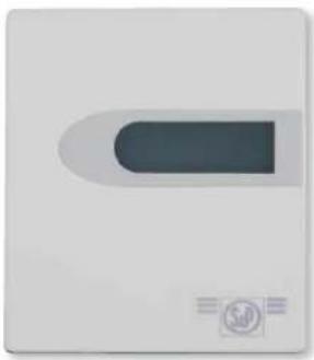
Blank white square with a small circular logo in the bottom right corner (no text or symbols)Model SCO2-A
SCO2 / SHT / SCHT
Ambient sensors that, combining with a control, allow optimizing the energy of the ventilation system.
| Model Lecture | Analog | output | Adjustable relay output | Display | ||
| CO_2 | Temperature HR | |||||
| SC02-A··· | ||||||
| SC02-AD···· | ||||||
| SC02-A 0/10V···· | ||||||
| SHT-A···· | ||||||
| SCHT-AD···· | ||||||
natural_image
White electronic device with a rectangular lens and indicator lights (no visible text or symbols)Models SCO2-AD and SCHT-AD
| Model | Electrical supply | Power (W) | Voltage | Heihgt installation | IP protection | CO_2 Range | Temperature range | HR Range | Dimensions LxWxH (mm) |
| SCO2-A | 24VDC-24VAC | 5 | 4-20mA | 1,5-3,5 m | IP20 | 0-2000 pm | 0-50°C | - | 85x26x100 |
| SCO2-AD | - | ||||||||
| SCO2-A 0/10V | - | ||||||||
| SHT-A | - | 0-100% | |||||||
| SCHT-AD | 0-10V | 0-2000 pm |

natural_image
Green and white industrial sensor device with a terminal handle (no visible text or symbols)SHT-G / SCO2-G /
SCO2-G 0/10V
Sensors for the duct that, combining with a control, allow optimizing the energy of the ventilation system.
| Model | Lecture | Analog output | ||
| CO_2 | Temperature | HR | ||
| SC02-G | • | • | ||
| SC02-G 0/10V • | • | |||
| SHT-G | • | • | • | |
| Model Electrical | Supply | Power (W) | Voltage IP | Protection | CO_2 Range | HR Range | Dimensions LxWxH (mm) |
| SC02-G | 24VDC-24VAC 5 | 4-20mA | Caja IP65. Sonda IP20 | 0-2000 pm | - | 80x200x101SCO2-G 0/10V | |
| SHT-G 0~100% | 0-10V | - | |||||
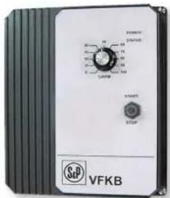
VFKB IP65
For three phase motors from 0.37 to 4 kW. Die cast aluminium IP65 case.
Simple to operate (does not require programming).
Voltage supplies: single phase
230V-50/60Hz (VFKB 24 and 27) three
phase 400V-50/60Hz (VFKB 45 and 48).
Motor kW selection jumper.
Power on and drive status leds.
Speed selection with potentiometer.
ON/OFF switch.
Run/Fault relay output contacts.
Motor overload and shortcut protections.
RFI/EMI level A filter.

The selection of the adjustable frequency drive has to be made with the maximum current absorbed of the fan or extractor.
| Model Power motor | (kW) | Maximum current (A) | Weight (kg) |
| Single phase supply 230V-50/60Hz, three phase output 230V | |||
| VFKB 24 | 0,37 2,2 | 2,7 | |
| 0,55 3,6 | |||
| VFKB 27 | 0,75 4,7 | 4,71,1 6,1 | |
| 1,5 6,7 | |||
| Three phase supply 400V-50/60Hz, three phase output 400V | |||
| VFKB 45 | 0,37 1,8 | 4,7 | |
| 0,55 2,1 | |||
| 0,75 2,8 | |||
| 1,1 3,4 | |||
| 1,5 4,6 | |||
| VFKB 48 | 2,2 5,6 | 4,73 7,8 | |
| 4 8,3 | |||
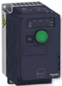
natural_image
Exterior view of a black industrial control unit with a green indicator knob (no visible text or symbols)
| Dims. a b c G H h | ||||
| T1 72 143 109 60 131 6 | ||||
| T2 72 143 128 60 121,5 6 | ||||
| T3 72 143 138 60 121,5 6 | ||||
| T4 105 142 158 93 118 5 | ||||
| T5 140 184 158 126 157 6,5 | ||||
| T6 150 308 232 130 210 5 | ||||
| T7 180 404 232 160 295 7 |

natural_image
Exterior view of a black industrial control unit with a green indicator light (no visible text or symbols)Configuration of three-phase supply models from 5.5 to 15kW.

| Dims. a b c G H h | ||||
| T1 72 143 109 60 131 6 | ||||
| T2 72 143 128 60 121,5 6 | ||||
| T3 72 143 138 60 121,5 6 | ||||
| T4 105 142 158 93 118 5 | ||||
| T5 140 184 158 126 157 6,5 | ||||
| T6 150 308 232 130 210 5 | ||||
| T7 180 404 232 160 295 7 |
VFTM320
Frequency converters for three-phase motors from 0.18 to 15kW. IP20 protection rating. VFTM320 MONO Models: 230V-50/60Hz single-phase supply voltage and 230V three-phase output. VFTM320 TRI Models: 400V-50/60Hz three-phase supply voltage and 400V three-phase output. External screen fo viewing parameters.
Front wheel for manual speed regulation (frequency).
Special plug & play configuration for constant pressure work modes or manual regulation with front wheel. Overload and short circuit protection. Integrated class 2 EMC filter.
Modbus and CANopen communication protocols integrated as standard.
The selection of the adjustable frequency drive has to be made with the maximum current absorbed of the fan or extractor.
| Modelo Power motor | (kW) | Maximum current (A) | Power dissipated (W) | Size reference | Weight (kg) |
| Single phase supply 230V-50/60Hz, three phase output 230V | |||||
| VFTM320 MONO 0,18 | 0,18 | 1,5 | 22 | T1 | 0,8 |
| VFTM320 MONO 0,37 | 0,37 | 3,3 | 32 | T2 | 1 |
| VFTM320 MONO 0,55 | 0,55 | 3,7 | 42 | T3 | 1,1 |
| VFTM320 MONO 0,75 | 0,75 | 4,8 | 48 | T3 | 1,1 |
| VFTM320 MONO 1,10 | 1,10 | 6,9 | 66 | T4 | 1,6 |
| VFTM320 MONO 1,5 | 1,5 | 8 | 82 | T4 | 1,6 |
| VFTM320 MONO 2,2 | 2,2 | 11 | 110 | T4 | 1,6 |
| Three phase supply 380/500V-50/60Hz + land, three phase output 400 V | |||||
| VFTM320 TRI 0,37 | 0,37 | 1,5 | 28 | T4 | 1,2 |
| VFTM320 TRI 0,55 | 0,55 | 1,9 | 33 | T4 | 1,2 |
| VFTM320 TRI 0,75 | 0,75 | 2,3 | 38 | T4 | 1,2 |
| VFTM320 TRI 1,10 | 1,10 | 3 | 47 | T4 | 1,3 |
| VFTM320 TRI 1,5 | 1,5 | 4,1 | 61 | T4 | 1,3 |
| VFTM320 TRI 2,2 | 2,2 | 5,5 | 76 | T5 | 2,1 |
| VFTM320 TRI 3 | 3 | 7,1 | 94 | T5 | 2,1 |
| VFTM320 TRI 4 | 4 | 9,5 | 112 | T5 | 2,2 |
| VFTM320 TRI 5,5 | 5,5 | 14,3 | 233 | T6 | 4,4 |
| VFTM320 TRI 7,5 | 7,5 | 17 | 263 | T6 | 4,4 |
| VFTM320 TRI 11 | 11 | 27,7 | 403 | T7 | 6,8 |
| VFTM320 TRI 15 | 15 | 33 | 480 | T7 | 6,9 |
REB-CVF

natural_image
Exterior view of a mechanical control unit with buttons and ports (no readable text or symbols)
Remote control ON/OFF + potentiometer
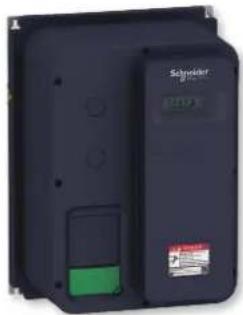
natural_image
Exterior view of a black industrial electrical control unit (no visible text or symbols)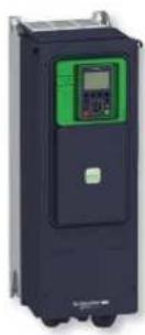
natural_image
Exterior view of a black industrial electrical control unit with green and black buttons (no visible text or symbols)Configuration of models VFTM650 TRI 11 and 15 IP55

| Dims. | a | b | c | G | H | h |
| T1 | 250 | 340 | 182 | 231 | 323 | 6,6 |
| T2 | 250 | 340 | 235 | 231 | 323 | 6,6 |
| T3 | 250 | 340 | 200 | 231 | 323 | 6,6 |
| T4 | 320 | 521 | 295 | 300 | 496 | 8 |

| a | b | c | G | i | H |
| 264 | 678 | 299 | 205 | 661 | 8 |
VFTM320 IP66 / VFTM650 IP55
Frequency converters for three-phase motors from 0.18 to 15kW. IP66 protection rating (IP55 models VFTM650 TRI 11 and 15 IP55)
VFTM320 MONO IP66
Models: 230V-50/60Hz single-phase supply voltage and 230V three-phase output.
VFTM320 TRI IP66 and VFTM650 TRI IP55 Models:
400V-50/60Hz three-phase supply voltage and 400V three-phase output. External screen for viewing parameters.
Internal front wheel for manual speed regulation (frequency).
Special plug & play configuration for constant pressure work modes or manual regulation with internal front wheel (except VFTM650 models, without factory plug & play configuration).
Overload and short circuit protection. Integrated class 2 EMC filter.
Modbus and CANopen communication protocols integrated as standard (except VFTM650 IP55 models, Modbus and Ethernet protocol).
The selection of the adjustable frequency drive has to be made with the maximum current absorbed of the fan or extractor.
| Model Power motor(kW) | Maximum current(A) | Power dissipated(W) | Size reference | Weight(kg) |
Single phase supply 230V-50/60Hz, three phase output 230V
| VFTM320 MONO 0,18 IP66 0,18 1,5 22 T1 5 | ||||
| VFTM320 MONO 0,37 IP66 0,37 3,3 32 T1 5,1 | ||||
| VFTM320 MONO 0,55 IP66 0,55 3,7 42 T1 5,1 | ||||
| VFTM320 MONO 0,75 IP66 0,75 4,8 48 T1 5,1 | ||||
| VFTM320 MONO 1,10 IP66 1,10 6,9 66 T2 7,4 | ||||
| VFTM320 MONO 1,5 IP66 1,5 8 82 T2 7,4 | ||||
| VFTM320 MONO 2,2 IP66 2,2 11 110 T2 7,4 |
Three phase supply 380/500V-50/60Hz + land, three phase output 400 V
| VFTM320 TRI 0,37 IP66 0,37 1,5 | 28 | T3 5,9 | |||
| VFTM320 TRI 0,55 IP66 0,55 1,9 | 33 | T3 5,9 | |||
| VFTM320 TRI 0,75 IP66 0,75 2,3 | 38 | T3 5,9 | |||
| VFTM320 TRI 1,10 IP66 1,10 3 | 47 | T3 6 | |||
| VFTM320 TRI 1,5 IP66 | 1,5 | 4,1 | 61 T3 6 | ||
| VFTM320 TRI 2,2 IP66 | 2,2 | 5,5 | 76 T2 7,7 | ||
| VFTM320 TRI 3 IP66 | 3 | 7,1 | 94 T2 7,7 | ||
| VFTM320 TRI 4 IP66 | 4 | 9,5 | 112 T2 7,8 | ||
| VFTM320 TRI 5,5 IP66 | 5,5 14,3 | 233 T4 | 22 | ||
| VFTM320 TRI 7,5 IP66 | 7,5 17 | 263 T4 | 22 | ||
| VFTM650 TRI 11 IP55 11 | 23,5 | 371 | See table 19,6 | 13,7 | |
| VFTM650 TRI 15 IP55 | 15 31,7 | 532 |
REB-CVF
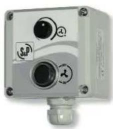
natural_image
Exterior view of a white industrial sensor or control unit with circular buttons and a central lens (no visible text or symbols)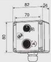
Remote control
ON/OFF + potentiometer

CONTROL ECOWATT
Control element for demand controlled ventilation systems in public, commercial residential building it automatically modifies the fan speed to adapt it to the needs defined in the system, measured with sensors.
It has three basic modes of operation:
- Integral proportional control at constant pressure.
- Proportional control with maximum demand criteria with multiple sensor input: temperature, CO_2 and relative humidity.
- Minimum-maximum control with three-sensor input: CO_2 , temperature, relative humidity or presence detectors (PIR).
DC signal output of 1 to 10 V or signal output for AC voltage variation for single phase motors at 230 V.
ECOWATT AC CONTROL: for single phase ventilation units.
ECOWATT DC CONTROL: for DC ventilation units.
Power supply:
- AC model: 1\~230 V.
- DC model: 1\~230 V or 24 VDC.
| Model Electrical | supply | Maximum current (A) | Voltage IP | Protection | Operating temperature range | Dimensions LxWxH (mm) |
| CONTROL ECOWATT AC/DC | 90-260 VAC | 4 | 0-10V | IP55 -10°C to +50°C 165x220x100 | ||
| CONTROL ECOWATT AC/4A | 230 VAC 80-230V | |||||

natural_image
Exterior view of a white electronic device with two labeled buttons (G and S&P) and mounting points (no readable text beyond labels)CONTROL ECOWATT BASIC
Control element for ECOWATT fans with DC brushless motor. It allows control via signal from an analogue output 0-10V depending on the status of three digital inputs free of power. Before each change of digital signal, it can be attributed a voltage output value between 0 and 10V.
Mode of operation:
- Remote ON/OFF with two speed switch.
- Up to three switch speeds taking as output the most unfavorable value.
| Model Electrical | supply | Maximum current (A) | Voltage IP Protection | Operating temperature range | Dimensions LxWxH (mm) | |
| CONTROL ECOWATT BASIC | 230 VAC | 6 | 0-10V | IP54 | -10°C to +50°C | 160x145x80 |

PROSYS ECOWATT
Programming console specific for ECOWATT PLUS series. Allows user selection and adjustment of any operating mode: constant pressure (COP), constant airflow value (CAV), variable air value (VAV) and minimum-maximum.
It includes an RJ45 cable of 1 meter length for connection to the fan.
| Model Dimensions | LxWxH (mm) |
| PROSYS ECOWATT 102x70x35 |

natural_image
Close-up of a green electronic component with a circular dial and terminal block (no readable text or symbols)TIMER RTC ECOWATT
Electronic unit specific for ECOWATT PLUS series. Allows user configuration of schedules with up to three daily slots, in addition to the holiday period.
The programing console PROSYS ECOWATT is also necessary.
| Model Dimensions | LxWxH (mm) |
| TIMER RTC ECOWATT 3x70x35 |
natural_image
White industrial electrical control box with three ports and a central indicator (no visible text or symbols)VAPZ
Electronic single-phase regulator that controls the fan speed with a simple contact (presence detector) or an analogical input, 0-10 V or 4-20 mA (CO₂ probe for relative humidity % RH).
Power supply: 1\~230 V.
| Model Electricalsupply | Maximumcurrent(A) | Voltage IP | Protection | Operatingtemperaturerange | DimensionsLxWxH(mm) | |
| VAPZ-3 | 230V-50Hz | 3 | 80 to 230V IP54 -10°C to +50°C | 205x115x92VAPZ-5 | 5 | |
| VAPZ-11 11 | ||||||

natural_image
Front view of a white electronic device with blue and beige buttons, displaying a digital display (no visible text or symbols)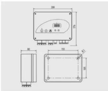
VRPU
Electronic control with display for single phase 230V-50/60Hz fans.
Analogical input 0-10V or 4-20mA: The fan works proportionally to the input value with adjustments of the minimum and maximum values of the inputs and outputs.
"ON/OFF": when the potential free contact (f.e. timer) close, the fan putting into operation according to the voltage of the analogical input. This connection associated to a PIR detector allows to have a ventilation system type minimum-maximum.
Input « maximum speed »: given an external signal, the fan works at a maximum adjusted speed.
Outputs: Magneto-termic dry contact.
Illumination 230V 50Hz (max. 8A).
Electrical supply master/slave 24Vdc (max. 100mA).
| Model Electrical supply | Maximum current (A) | Voltage | IP Protection | Operating temperature range | Dimensions LxWxH (mm) | |
| VRPU-5 | 230V-50/60Hz | 5 | 110V-230V | IP55 | -10°C to +50°C | 200x176x80 |
| VRPU-11 | 11 | |||||

natural_image
Front view of a white electronic device with blue control panel and connected ports (no visible text or symbols)PACK PR
Single phase motors.
Allows speed control of single phase fan by voltage variation.
Especially suited for constant pressure systems.
Includes a power cable and pressure tube.
Integrated pressure transducer (12VDC).
Supplied with cable glands.
Function integrated boost fan, adjustable from 10-60 min.
Display with three digits.
Entries for remote control "ON/OFF" + "select maximum speed".
Configurable input for analog sensor current / voltage / NTC thermistor sensor / Pt1000.
| Models Max. nominal current(A) | Pressure range(Pa) | DimensionsLxWxH(mm) |
| PACK PR 5A 5 0-300 176x200x80 | ||
| PACK PR 11A 11 0-800 176x200x80 |
| PACK PR | |
| Power supply Single phase 230V 50/60Hz | |
| Voltage range 110 - 230V | |
| ON / OFF input | Volt free contacts |
| Maximum speed input | |
| Remote setpoint input (control mode) Signal 4-20mA or voltage 0-10Vdc | |
| Measurement input (servo control or control mode) | Signal 4-20mA or voltage 0-10Vdc,or NTC thermistor sensor, or Pt1000 sensor |
| Outputs | Sensor supply: 24Vdc SELV (100mA max)Master-slave: 0-10Vdc (10mA max) |
| Electrical insulation Class 1 | |
| IP Protection IP55 | |
| Connections available | 1 to 2.5 mm ^2 Glands provided: 5xPg7 + 3xPg11 |
| Conditions of use -10 to +50 °C, max 95% RH | |

natural_image
Interior view of an open white electronic enclosure showing internal circuit boards and components (no visible text or symbols)BEAS
Control module that can adapt the all/nothing proportional input signal of a detector or a probe to control a motorised flap, or a two-speed single phase or DC_fan, in minimum/maximum option. Power supply: 24 VAC / 24 VDC.
| Model Electricalsupply | Power(W) | IP Protection Operating | DimensionsLxWxH(mm) | |
| temperaturerange | ||||
| BEAS 24VAC 1,5 IP55 | -10°C to +50°Cmax 95% HR | 175x130x80 | ||

natural_image
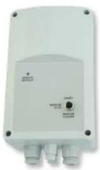
White industrial rotary dial with numbered terminals (0–10) and a small logo on the right (no readable text or symbols beyond labels)REB-ECOWATT
Remote speed control. Enables the speed control of the fan continuously, manually and remote. Power supply: 1-230 V.
| Model IP | Protection | Class Operating temperature range | Dimensions LxWxH (mm) |
| REB-ECOWATT IP44 II -10°C to +50°C 80x68x80 | |||

TDP-S / TDP-D / TDP-PI
TDP-S
Pressure sensor.
TDP-D
Pressure sensor, with display.
TDP-PI
Pressure sensor with display and integral proportional control by set point. Direct control output signal for ECOWATT fans or VFTM frequency inverters.
Pressure sensors. This sensors are used to control the pressure of DCV systems with constant pressure (COP). They allow the reading of the difference of pressures between two points and transform it into an analog signal suitable for the different control devices.
| Model Electrical supply | Maximum power (VA) | Connector (mm) | Voltage IP | Protection | Pressure range | Dimensions LxWxH (mm) | |
| TDP-S | 24VAC-24VDC | 4 | 6,2 | 0-10 V / 4-20 mA | IP54 | 0-2500 Pa | 91x75x36 |
| TDP-D | |||||||
| TDP-PI | |||||||
CPTA-S N / CPTA-E N
natural_image
Side view of a plain white rectangular object with no visible text or symbols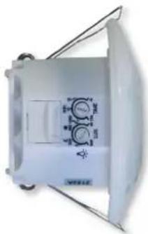
natural_image
Exterior view of a white industrial fan or vent with control knobs and indicator lights (no visible text or symbols)CPTA-S N CPTA-E N
Presence detector for ceiling mount, sensitive to infrared radiation emitted by bodies in movement, with a 360° detecting angle. They incorporate an output to activate a fan (potential - free) Power supply: 1-230 V.
CPTA-S N: Surface model.
CPTA-E N: Flush mount model.
| Electrical supply | Power (W) | Lighting output | Lighting tuning | Ventilation output | Ventilation tuning Installation | IP Protection | Operating temperature range | Condiciones funcionamiento | |
| Height | |||||||||
| CPTA-S N | Relay 230V normally open, power cut 10A | Luminosity 5 - 1000 lux Timing 15s - 30min | Free contact voltage normally opened. Up to 250Vac or 30Vcc, max. 2A. Independent to output lighting. | Timing 10s - 120min | IP54 | -25 to 55°C max. 90% HR without condensation | |||
| CPTA-E N | 230V-50/60Hz 0,5 | Luminosity 10 - 2000 lux Timing 5s - 20min | Free contact voltage normally opened. Up to 250Vac or 30Vcc. 5A (resistive load) or 1A (inductive load). Independent to output lighting. | Timing 10s - 60min | 2,5 -3,5m | IP44 (Terminal box, IP20) | 0 to 45°C max. 90% HR without condensation | ||
Surface mounting In-place mounting

natural_image
Close-up of a black cylindrical device with attached electronic component (no visible text or symbols)REMP
Motorised dampers open proportionately and is controlled by the BEAS control module.
Power supply: 24 VAC or 24 VD, depending on the models.
| Model Diameter | (mm) | Length (mm) | Axle diameter (mm) | Motor height (mm) |
| REMP-160 160 200 8 80 | ||||
| REMP-200 200 200 8 80 | ||||
| REMP-250 250 200 8 80 | ||||
| REMP-315 315 300 12 80 | ||||
| REMP-355 355 300 12 80 | ||||
| REMP-400 400 400 12 80 | ||||
| REMP-450 450 400 12 80 | ||||
| REMP-500 500 400 12 80 |
| Model Electrical supply | Power (W) | Entry Time of answer | IP Protection | Operating temperature range | ||
| REMP | 24V-50/60Hz 24VDC | 1 (ON) 0,4 (OFF) | 0-10V proportional | max. 150s on having opened or to closed | IP54 | -10°C to +50°C maximum 95% HR without condensation |

natural_image
Close-up of a metallic cylindrical industrial component with internal cavities and mounting bracket (no visible text or symbols)RMVT
Motorised dampers for the twin-flow system. Minimum / maximum opening. Controlled by a presence detector acting on the motor of the damper. Power supply: 1-230 V.
| Model ∅ | (mm) | Air volume |
| RMVT-125 12/100 125 | 12/100 | |
| RMVT-125 12/120 125 | 12/120 | |
| RMVT-125 30/90 | 125 | 30/90 |
| RMVT-125 60/120 125 | 60/120 | |
| RMVT-125 60/135 125 | 60/135 | |
| RMVT-125 90/150 125 | 90/150 | |
| RMVT-160 15/150 160 | 15/150 | |
| Model ∅ | (mm) | Air volume |
| RMVT-160 24/240 160 | 24/240 | |
| RMVT-160 30/300 160 | 30/300 | |
| RMVT-200 40/210 200 | 40/210 | |
| RMVT-200 40/350 200 | 40/350 | |
| RMVT-200 40/400 200 | 40/400 | |
| RMVT-200 50/500 200 | 50/500 |
| Model Electrical supply | Power (W) | Entry Time of answer | IP Protection | Class Operating temperature range | ||
| RMVT 230V-50Hz | 6,6 | Contact type outside presence detector | 40s opening 80s closed | IP20 | Class II | 0°C to +60°C maximum 95% HR without condensation |

natural_image
White industrial control unit labeled 'TRAFO15/D' with no visible text or symbols on its bodyTRAFO 15-D
Transformer 230/24V AC.

CONTROL ETT-6
Electronic step controller. Can control activation of up to six devices. Can be used to switch on and off heating systems (EC wall-mounted fan heaters or TERMOTECH radiant panels) or for ventilations systems with several units.
| Model Power | source | Maximum consumption (VA) | Relés Protection | index | Operating temperature (°C) | Dimensions (mm) | |||
| Number Max. intensity (A) | L A H | ||||||||
| CONTROL ETT-6 | 230V±10%50/60Hz | 6 6 6 IP20 | 0°C a 40°C | 156 110 72 | |||||
natural_image
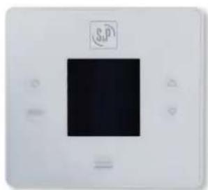
White electronic device with a black square display and a small circular logo above it (no readable text or symbols)CR-TEMP
Ambient temperature controller with an electronic sensor inside. Allows for manual or automatic control of ON/OFF switch with the following functions:
- Setpoint temperature
- Weekly programming that can switch on and off twice a day
- Detects open windows from quick drop in temperature
- Manual override. Includes an electronic sensor that reads room temperature
| Model Power | source | Maximum consumption (W) | Relay ON/ OFF Max. intensity (A) | Protection index | Operating temperature (°C) | Dimensions (mm) | ||
| L | A | H | ||||||
| CR-TEMP | 100-250V 50/60Hz | 0,5 | 5 (resistivos) | IP20 | 0°C a 40°C | 100 | 95 | 25 |
CAR PARK CONTROL PANEL

natural_image
Exterior view of a white industrial cabinet with a door and control panel (no visible text or symbols)
natural_image
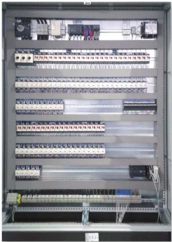
Interior view of an electrical control cabinet with multiple circuit boards and wiring (no visible text or labels)Specific applications

Car parks
Applications
Jet fan ventilation systems in enclosed car parks require control system to operate exhaust, supply and jet fans either for manual activation or depending on the inputs from pollution/smoke detection systems. S&P has developed a tailor-made, pre-programmed PLC control panel with user-friendly interface through touchscreen, allowing system's activation at high and low pollution ventilation and emergency smoke extract modes.
Main features
Adapted: different regulations may apply depending on the country hence activation may be manual, automatic by detection or a combination of both.
Efficient: an intelligent control adjusted to the demand, capable to operate a system with defined zoning according to a specific ventilation strategy, to reduce the power consumption of the system and providing and improved performance.
Plug & play: simplified installation with identified terminals for each motor.
Smart: specific programming as per our CFD team recommendations. Includes maintenance guidance to be done and identification of eventual failures by alarm.
Operation Modes
• Automatic: activation by detection.
- Manual: activation per ventilation zones.
- Maintenance: motor and detectors management, weekly schedule.
• Technical service: safety parameters.
Description
• Tailored Control System for car park ventilation systems.
• Electrical protection and control by PLC for all the components of the ventilation system.
• Three-phase 400V 50/60Hz.
• Available for TN or TT connection.
- Metallic cabinet, IP55. Dimensions depend on the number of fan motors supplied.
• Master isolator switch.
- Compatible with single-speed and two-speed motors (Dahlander and independent windings).
- Touchscreen with user friendly interface.
- Communication with the detection system (CO/NO, and fire) for automatic operation.
• Fire-fighters emergency stop included.
- Guide with tagged and numbered terminals for each motor.
- Car park drawings with fan location and status.
• Additional 2100x400x400mm cabinet for powers over 110 kW.
• Electrical schemes and CE certification.
- Interface available in English, French or Spanish.
• Fan maintenance alarms.
On request
- Motors equipped with Variable Speed Drive. Please note that DV/Dt filters might be required depending on the cable length necessary to connect VSD with fan motors.
- Remote access for technical assistance and software update.
- Mirroring of the touchscreen in tablets or smartphones.
- Connectivity with Building Monitoring Systems (BMS).
- Coordination with other equipment of the car park systems: motorized dampers, smoke curtains, etc.
natural_image
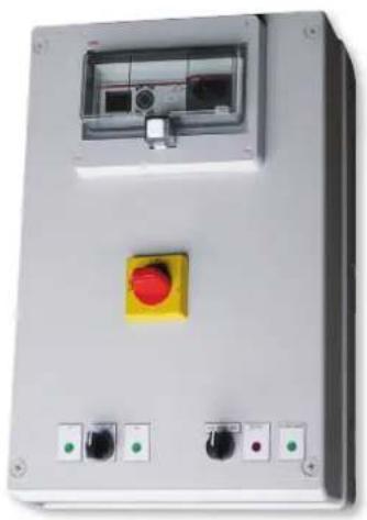
Exterior view of an electrical control box with a yellow indicator light and terminal blocks (no visible text or symbols)PILOT PARC

natural_image
White industrial electrical box with a yellow button and three metallic buttons at the bottom (no visible text or symbols)
Model A B C D E
| Size 1 | 362 | 254 | 200 | 371 | 239 |
| Size 2 | 570 | 380 | 175 | 600 | 355 |
| Size 3 | 600 | 300 | 235 | 550 | 216 |
| Size 4 | 600 | 500 | 300 | 640 | 456 |
| Size 5 | 700 | 500 | 300 | 740 | 456 |
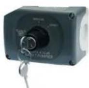
BAPA firefighter stop, at the reference level near each vehicle access.

Centralized control BCCP unit for fire safety start / firefighter stop / pollution ventilation, at the reference level near each vehicle access.

BCCA 2V two-speed pollution ventilation control unit, inside the car park.
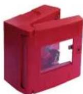
Fire alarm switch BDRA or BDBG (glass cover), at each level and at the reference level near each vehicle access.

BREA reset unit, inside the car park.
Application
Master – Slave control panels for exhaust and supply fans in car park ventilation systems.
For three-phase 400V two-speed motor control (Dahlander or independent windings).
For single speed fans, select the units for independent windings and connect only the high speed.
Operation through pollution and fire detection systems inputs, as well as manual control.
Operates fans at low speed (LS) and high speed (HS) for pollution ventilation, and high speed (HS) for emergency smoke extract modes.
General data
To be installed outside the fire-smoke area. IP55, RAL 7035 colour.
Sizes 1 – 3, reinforced polycarbonate enclosure.
Sizes 4 - 5, steel enclosure.
Isolator switch in front panel, padlockable in 3 positions.
Cableglands and mounting kits included.
Three phase supply 400V 50/60Hz + PE.
Thermal protections included, only considered for pollution ventilation mode,
FLC to be specified while placing the order.
Types
Master units for managing fan speed (OFF/LS/HS) based on pollution/smoke detection panels inputs.
Priorities for pollution (LS/HS), smoke extract (HS) and fire-fighters stop (OFF).
Manual control from front panel switches or accessories (BCCA).
Built-in weekly schedule for daily ventilation. 24V output for external commands' supply. Modbus TCP/IP communication included.
Communicating version for CMSI available.
- Safety remote control input by 24V or 48Vdc signal emitted by the CMSI.
- Std-by and safety information report for the CMSI.
Units for one two-speed motor of 9 / 18 / 25 / 32 / 50 / 65 / 80 / 95 amps. Higher amps on demand.
- 32A and above may control up to 3 Slave units, of any amp rate. These include magnet protection for short-circuit.
9, 18 and 25A units, to be added by the installer.
Units for two two-speed motors for 9 / 18 / 25 amps. May control up to 6 Slave units, of any amp rate. These include magnet protection for short-circuit for all amp rates. Slave units to be controlled by a Master unit. Units for one two-speed motor of 9 / 18 / 25 / 32 / 50 / 65 / 80 / 95 amps. Higher amps on demand.
- 32A and above may control up to 3 Slave units, of any amp rate. These include magnet protection for short-circuit.
9, 18 and 25A units, to be added by the installer.
LIST OF PILOT PARC MODELS
Models with Dahlander connexion motor
| Intensity (A) | Master with timer for 1 Dahlander connexion motor | Slave without timer for 1 Dahlander connexion motor | ||
| Model Box | type-size | Model Box | type-size | |
| 9 PILOT PARC MH1DA 9A 2 PILOT PARC E1DA 9A 1 | ||||
| 18 PILOT PARC MH1DA 18A 2 PILOT PARC E1DA 18A 1 | ||||
| 25 PILOT PARC MH1DA 25A 2 PILOT PARC E1DA 25A 1 | ||||
| 32 PILOT PARC MH1DA 32A 3 PILOT PARC E1DA 32A 3 | ||||
| 50 PILOT PARC MH1DA 50A 3 PILOT PARC E1DA 50A 3 | ||||
| 65 PILOT PARC MH1DA 65A 3 PILOT PARC E1DA 65A 3 | ||||
| 80 PILOT PARC MH1DA 80A 3 PILOT PARC E1DA 80A 3 | ||||
| 95 PILOT PARC MH1DA 95A 5 PILOT PARC E1DA 95A 4 | ||||
| Intensity (A) | Master with timer for 2 Dahlander connexion motors | |
| Model Box | type-size | |
| 9 PILOT PARC MH2DA 9A 2 | ||
| 18 PILOT PARC MH2DA 18A 2 | ||
| 25 PILOT PARC MH2DA 25A 2 | ||
Models with independent windings motor
| Intensity (A) | Master with timer for 1 motor of independent windings | Slave without timer for 1 motor of independent windings | ||
| Model Box | type-size | Model Box | type-size | |
| 9 PILOT PARC MH1BI 9A 2 PILOT PARC E1BI 9A | 1 | |||
| 18 PILOT PARC MH1BI 18A | 2 PILOT PARC E1BI 18A | 1 | ||
| 25 PILOT PARC MH1BI 25A | 2 PILOT PARC E1BI 25A | 1 | ||
| 32 PILOT PARC MH1BI 32A | 3 PILOT PARC E1BI 32A | 3 | ||
| 50 PILOT PARC MH1BI 50A | 3 PILOT PARC E1BI 50A | 3 | ||
| 65 PILOT PARC MH1BI 65A | 3 PILOT PARC E1BI 65A | 3 | ||
| 80 PILOT PARC MH1BI 80A | 3 PILOT PARC E1BI 80A | 3 | ||
| 95 PILOT PARC MH1BI 95A | 5 PILOT PARC E1BI 95A | 4 | ||
| Intensity (A) | Master with timer for 2 motors of independent windings | |
| Model Box | type-size | |
| 9 PILOT PARC MH2BI 9A 2 | ||
| 18 PILOT PARC MH2BI 18A 2 | ||
| 25 PILOT PARC MH2BI 25A 2 | ||
Models with CMSI connectivity, with Dahlander connection motor
| Intensity (A) | Master with timer for 1 Dahlander - CMSI connection motor | |
| Model | Box type-size | |
| 9 | PILOT PARC MH1 DA 9A CMSI | 1 |
| 18 | PILOT PARC MH1 DA 18A CMSI | 1 |
| 25 | PILOT PARC MH1 DA 25A CMSI | 1 |
| 32 | PILOT PARC MH1 DA 32A CMSI | 3 |
| 50 | PILOT PARC MH1 DA 50A CMSI | 3 |
| 65 | PILOT PARC MH1 DA 65A CMSI | 3 |
| 80 | PILOT PARC MH1 DA 80A CMSI | 3 |
| 95 | PILOT PARC MH1 DA 95A CMSI | 4 |
| Master with timer for 2 Dahlander - CMSI connection motor | |
| Model | Box type-size |
| PILOT PARC MH2 DA 9A CMSI | 1 |
| PILOT PARC MH2 DA 18A CMSI | 1 |
| PILOT PARC MH2 DA 25A CMSI | 1 |
Models with CMSI connectivity, with independent windings motor
| Intensity (A) | Master with timer for 1 independent windings motor - CMSI | |
| Model | Box type-size | |
| 9 | PILOT PARC MH1BI 9A CMSI | 2 |
| 18 | PILOT PARC MH1BI 18A CMSI | 2 |
| 25 | PILOT PARC MH1BI 25A CMSI | 2 |
| 32 | PILOT PARC MH1BI 32A CMSI | 3 |
| 50 | PILOT PARC MH1BI 50A CMSI | 3 |
| 65 | PILOT PARC MH1BI 65A CMSI | 3 |
| 80 | PILOT PARC MH1BI 80A CMSI | 3 |
| 95 | PILOT PARC MH1BI 95A CMSI | 5 |
| Master with timer for 1 independent windings motor - CMSI | |
| Model | Box type-size |
| PILOT PARC MH2BI 9A CMSI | 2 |
| PILOT PARC MH2BI 18A CMSI | 2 |
| PILOT PARC MH2BI 25A CMSI | 2 |
CONTROLS SCHEME MODEL
SYNOPTIC 1 MOTOR

flowchart
graph TD
    A["ΔP"] --> B["Three-phase supply 400V 50/60Hz + PE"]
    B --> C["PILOT PARC MASTER 1 motor"]
    C --> D["BREA"]
    D --> E["BCCA 2V"]
    E --> F["Firefighter stop"]
    F --> G["LS / HS"]
    G --> H["Central CO / NO2 (not included)"]
    H --> I["Vehicle access to parking"]
    J["BDRA or BDBG or signal emitted by CMSI"] --> K["Vehicle access to parking"]
    L["BAPA"] --> M["Vehicle access to parking"]
    N["Space outside the risk area (Protected area)"] --> O["Fire-resistant cable"]
    N --> P["Conventional cable"]
    Q["EMergency HS"] --> R["Firefighter stop"]
Possibility of replacing units BREA + BDRA / BDBG + BAPA by the centralized unit BCCP.
1 MOTOR SELECTION

flowchart
graph TD
    A["Control for 1 motor"] --> B["1-speed fan"]
    A --> C["2-speed fan Polluting LS/HS HS in emergency"]
    B --> D["Tri 400V"]
    C --> E["Tri 400V independent windings"]
    C --> F["Tri 400V Dahlander winding"]
    D --> G["PILOT PARC MH 1 BI* PILOT PARC MH 1 BI PILOT PARC MH 1 DA"]
    E --> H["..."]
    F --> I["..."]
* Use of PILOT PARC only in HS output.
CONTROLS SCHEME MODEL
SYNOPTIC 2 MOTORS
1 PILOT PARC MASTER for 2 motors

flowchart
graph TD
    A["Three-phase supply 400V 50/60Hz + PE"] --> B["INTZ PILOT PARC MASTER 2 motors ≤25A"]
    B --> C["LS / HS"]
    B --> D["BREA"]
    B --> E["BCCA 2V"]
    B --> F["Firefighter stop"]
    B --> G["ΔP"]
    B --> H["ΔP"]
    B --> I["Central CO / NO2 (not included)"]
    style A fill:#FFD700,stroke:#333
    style B fill:#FFD700,stroke:#333
    style C fill:#FFD700,stroke:#333
    style D fill:#FFD700,stroke:#333
    style E fill:#FFD700,stroke:#333
    style F fill:#FFD700,stroke:#333
    style G fill:#FFD700,stroke:#333
    style H fill:#FFD700,stroke:#333
    style I fill:#FFD700,stroke:#333
    note right of B: "Three-phase supply 400V 50/60Hz + PE"
    note right of B: "Fire-resistant cable"
    note right of B: "Conventional cable"
    note right of B: "Vehicle access to parking"
    note right of B: "BDRA or BDBG or signal emitted by CMSI"
    note right of B: "BAPA"
1 PILOT PARC MASTER for 1 motor + 1 PILOT PARC SLAVE for 1 motor

flowchart
graph TD
    A["ΔP"] --> B["Three-phase supply 400V 50/60Hz + PE"]
    B --> C["PILOT PARC MASTER 1 motor >25A"]
    C --> D["INTZ"]
    D --> E["Emergency HS"]
    D --> F["Firefighter stop"]
    F --> G["ΔP"]
    H["BCCA 2V"] --> C
    I["Central CO / NO2 (not included)"] --> C
    J["BREA"] --> K["Three-phase supply 400V 50/60Hz + PE"]
    K --> L["PILOT PARC SLAVE"]
    L --> M["INTZ"]
    M --> N["LS / HS"]
    N --> O["Vehicle access to parking"]
    P["BDRA or BDBG or signal emitted by CMSI"] --> Q["Vehicle access to parking"]
    R["BAPA"] --> S["Vehicle access to parking"]
Possibility of replacing units BREA + BDRA / BDBG + BAPA by the centralized unit BCCP.
2 MOTORS SELECTION
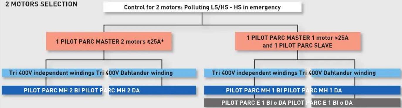
flowchart
graph TD
    A["Control for 2 motors: Polluting LS/HS - HS in emergency"] --> B["1 PILOT PARC MASTER 2 motors ≤25A*"]
    A --> C["1 PILOT PARC MASTER 1 motor >25A and 1 PILOT PARC SLAVE"]
    B --> D["Tri 400V independent windings Tri 400V Dahlander winding"]
    B --> E["PILOT PARC MH 2 BI PILOT PARC MH 2 DA"]
    C --> F["Tri 400V independent windings Tri 400V Dahlander winding"]
    C --> G["PILOT PARC MH 1 BI PILOT PARC MH 1 DA"]
    C --> H["PILOT PARC E 1 BI o DA PILOT PARC E 1 BI o DA"]
* Selection of the caliber of the PILOT PARC MASTER for 2 motors based on the rated current HS of the higher amperage motor it controls.
CONTROLS SCHEME MODEL
SYNOPTIC > 2 MOTORS

flowchart
graph TD
    A["Three-phase supply 400V 50/60Hz + PE"] --> B["PILOT PARC MASTER"]
    B --> C["SL / HS"]
    B --> D["INTZ"]
    B --> E["PILOT PARC SLAVE"]
    E --> F["Vehicle access to parking"]
    B --> G["BCCA 2V"]
    G --> H["Central CO / NO2 (not included)"]
    H --> I["ΔP"]
    H --> J["BREA"]
    B --> K["INTZ"]
    K --> L["Emergency HS"]
    L --> M["Firefighter stop"]
    M --> N["BSRA or BDBG or signal emitted by CMSI"]
    M --> O["BAPA"]
    style A fill:#f9f,stroke:#333
    style B fill:#ff9,stroke:#333
    style C fill:#ffcc,stroke:#333
    style D fill:#ffcc,stroke:#333
    style E fill:#ffcc,stroke:#333
    style F fill:#ffcc,stroke:#333
    style G fill:#ffcc,stroke:#333
    style H fill:#ffcc,stroke:#333
    style I fill:#ffcc,stroke:#333
    style J fill:#ffcc,stroke:#333
    style K fill:#ffcc,stroke:#333
    style L fill:#ffcc,stroke:#333
    style M fill:#ffcc,stroke:#333
    style N fill:#ffcc,stroke:#333
    style O fill:#ffcc,stroke:#333
1 PILOT PARC MASTER for 1 motor + 3 PILOT PARC SLAVE for 1 motor each

flowchart
graph TD
    A["Three-phase supply 400V 50/60Hz + PE"] --> B["Vehicle access to parking"]
    B --> C["PILOT PARC SLAVE INTZ"]
    B --> D["PILOT PARC MASTER 1 motor >25A"]
    C --> E["BCCA 2V"]
    D --> F["Central CO / NO2 (not included)"]
    D --> G["INTZ"]
    D --> H["INTZ"]
    D --> I["BIWA"]
    D --> J["BIWA"]
    D --> K["BIWA"]
    D --> L["BIWA"]
    D --> M["BIWA"]
    D --> N["BIWA"]
    D --> O["BIWA"]
    D --> P["BIWA"]
    D --> Q["BIWA"]
    D --> R["BIWA"]
    D --> S["BIWA"]
    D --> T["BIWA"]
    D --> U["BIWA"]
    D --> V["BIWA"]
    D --> W["BIWA"]
    D --> X["BIWA"]
    D --> Y["BIWA"]
    D --> Z["BIWA"]
    D --> AA["BIWA"]
    D --> AB["BIWA"]
    D --> AC["BIWA"]
    D --> AD["BIWA"]
    D --> AE["BIWA"]
    D --> AF["BIWA"]
    D --> AG["BIWA"]
    D --> AH["BIWA"]
    D --> AI["BIWA"]
    D --> AJ["BIWA"]
    D --> AK["BIWA"]
    D --> AL["BIWA"]
    D --> AM["BIWA"]
    D --> AN["BIWA"]
    D --> AO["BIWA"]
    D --> AP["BIWA"]
    D --> AQ["BIWA"]
    D --> AR["BIWA"]
    D --> AS["BIWA"]
    D --> AT["BIWA"]
    D --> AU["BIWA"]
    D --> AV["BIWA"]
    D --> AW["BIWA"]
    D --> AX["BIWA"]
    D --> AY["BIWA"]
    D --> AZ["BIWA"]
    D --> BA["BIWA"]
    D --> BB["BIWA"]
    D --> BC["BIWA"]
    D --> BD["BIWA"]
    D --> BE["BIWA"]
    D --> BF["BIWA"]
    D --> BG["BIWA"]
    D --> BH["BIWA"]
    D --> BI["BIWA"]
    D --> BJ["BIWA"]
    D --> BK["BIWA"]
    D --> BL["BIWA"]
    D --> BM["BIWA"]
    D --> BN["BIWA"]
    D --> BO["BIWA"]
    D --> BP["BIWA"]
    D --> BQ["BIWA"]
    D --> BR["BIWA"]
    D --> BS["BIWA"]
    D --> BT["BIWA"]
    D --> BU["BIWA"]
    D --> BV["BIWA"]
    D --> BW["BIWA"]
    D --> BX["BIWA"]
    D --> BY["BIWA"]
    D --> BZ["BIWA"]
Examples of installations with 4 motors.
Possibility of replacing units BREA + BDRA / BDBG + BAPA units with the BCCP centralized unit.
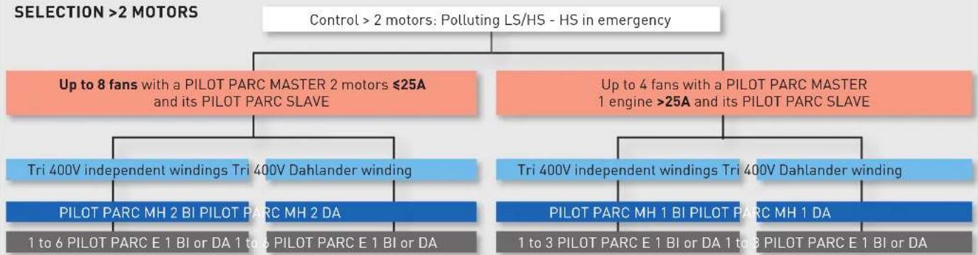
flowchart
graph TD
    A["Control > 2 motors: Polluting LS/HS - HS in emergency"] --> B["Up to 8 fans with a PILOT PARC MASTER 2 motors ≤25A and its PILOT PARC SLAVE"]
    A --> C["Up to 4 fans with a PILOT PARC MASTER 1 engine >25A and its PILOT PARC SLAVE"]
    B --> D["Tri 400V independent windings Tri 400V Dahlander winding"]
    B --> E["PILOT PARC MH 2 BI PILOT PARC MH 2 DA"]
    B --> F["1 to 6 PILOT PARC E 1 BI or DA 1 to 6 PILOT PARC E 1 BI or DA"]
    C --> G["Tri 400V independent windings Tri 400V Dahlander winding"]
    C --> H["PILOT PARC MH 1 BI PILOT PARC MH 1 DA"]
    C --> I["1 to 3 PILOT PARC E 1 BI or DA 1 to 3 PILOT PARC E 1 BI or DA"]
The 2-motor PILOT PARC MASTER can control from 1 to 6 PILOT PARC SLAVE of any caliber.
The PILOT PARC MASTER 1 motor >25A can control from 1 to 3 PILOT PARC SLAVE of any caliber.

PARKING DETECTION PANEL
For simultaneous detection of both CO and NO_2 in a same loop. It allows for control of up to 16 detectors with the possibility of programming up to 2 groups, making it possible to carry out individual maneuvers in the case of different gases, or sectorized maneuvers in the case of the same gas being detected.
Expandable from one to four totally independent module lines.
Each detector is monitored individually, showing its status in real time on the display.
Programmed with Spanish or Portuguese standards, with the possibility of programming for Spanish, Portuguese and English languages.
PARKING DETECTION PANELS Model
PARKING DETECTION PANEL 1 ZONE
PARKING DETECTION PANEL 2 ZONE
PARKING DETECTION PANEL 3 ZONE
PARKING DETECTION PANEL 4 ZONE
natural_image
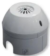
Exterior view of a white industrial air purifier with ventilation grille and mounting bracket (no text or symbols visible)DETECTOR W/BASE
CO and NO_2 detectors, with electrochemical probe.
Low sensitivity to interfering gases.
DETECTOR W/BASE Models
CO DETECTOR W/BASE
NO2 DETECTOR W/BASE
- REB-5
- REB-10
- RRB-100
- RMB
- RMT
- PARO/MARCHA 5P and PARO/MARCHA 8P
- DESENFUMAGE SWITCHES
- INTZ
- INTZ ATEX
- MSD
- DEMZ BI
- DEMZ DA
- REGUL-2
- COM-2
- COM-3
- INTER 4P
- INTERRUPTOR VMC 2V
- PRESOSTATO DPS
- CT-12/14 and CT-12/14R
- HIG-2
- SQA
- THE 16/4 A
- THE-F thermostat with capillary tube anti-frost sensor
- TIMER ZN 62
- PULSER
- PULSER-ADD
- PULSER-M
- PULSER-D
- TTC-2000
- TT-S1
- TT-S6/D
- TTC-25 and TTC-40F
- TG-R
- TG-K
- TBI
- TBI-10
- TBI-30
- MCR-1
- Thermostat
- The temperature control unit for MBW 100-200
- Model
- AIRSENS
- Main features:
- All-in-one:
- Standard version
- Communication with ventilation unit
- RF version
- WIFI version
- Connectair
- SCO2 / SHT / SCHT
- SHT-G / SCO2-G /
- SCO2-G 0/10V
- VFKB IP65
- VFTM320
- The selection of the adjustable frequency drive has to be made with the maximum current absorbed of the fan or extractor.
- REB-CVF
- VFTM320 IP66 / VFTM650 IP55
- VFTM320 MONO IP66
- VFTM320 TRI IP66 and VFTM650 TRI IP55 Models:
- CONTROL ECOWATT
- CONTROL ECOWATT BASIC
- Mode of operation:
- PROSYS ECOWATT
- TIMER RTC ECOWATT
- VAPZ
- VRPU
- PACK PR
- BEAS
- REB-ECOWATT
- TDP-S / TDP-D / TDP-PI
- TDP-S
- TDP-D
- TDP-PI
- CPTA-S N / CPTA-E N
- REMP
- RMVT
- TRAFO 15-D
- CONTROL ETT-6
- CR-TEMP
- CAR PARK CONTROL PANEL
- Applications
- Main features
- Operation Modes
- Description
- On request
- Application
- General data
- Types
- 9, 18 and 25A units, to be added by the installer.
- LIST OF PILOT PARC MODELS
- CONTROLS SCHEME MODEL
- PARKING DETECTION PANEL
- PARKING DETECTION PANELS Model
- DETECTOR W/BASE
- DETECTOR W/BASE Models
Brand : Soler & Palau
Model : REB-ECOWATT
Category : Controller