
SlamPak SLPK-YA-VXWR-SG-WH - Pregnant JL Audio - Free user manual and instructions
Find the device manual for free SlamPak SLPK-YA-VXWR-SG-WH JL Audio in PDF.


| Product Type | Marine Audio System (SlamPak) |
| Brand | JL Audio |
| Model | SLPK-YA-VXWR-SG-WH |
| Compatible Vessels | 2015-2019 Yamaha VX Models |
| Speakers | Two VeX Speaker Enclosures |
| Continuous Power Handling (RMS) | 60 Watts per Speaker |
| Nominal Impedance | 4 Ohms |
| Frequency Response | 100 Hz - 25 kHz (±3 dB) |
| Amplifier | JL Audio MX280/4 (4-channel, preset) |
| Bluetooth Controller | MBT-CRXv2 (integrated) |
| Power Supply | 12V DC (connection to vessel battery) |
| Circuit Breaker | 40A Included |
| Installation Difficulty | Moderate (estimated 3-4 hours) |
| Hardware Included | Mounting inserts, adaptors, bolts, connectors, template, cable ties, heat shrink, etc. |
| Color | White (SKU# 94653) |
| Marine Grade | Yes (designed for marine environment) |
| Warranty | Contact JL Audio for details |
| Recommended Installation | Professional installation recommended for safety |
Frequently Asked Questions - SlamPak SLPK-YA-VXWR-SG-WH JL Audio
User questions about SlamPak SLPK-YA-VXWR-SG-WH JL Audio
0 question about this device. Answer the ones you know or ask your own.
Ask a new question about this device
Download the instructions for your Pregnant in PDF format for free! Find your manual SlamPak SLPK-YA-VXWR-SG-WH - JL Audio and take your electronic device back in hand. On this page are published all the documents necessary for the use of your device. SlamPak SLPK-YA-VXWR-SG-WH by JL Audio.
USER MANUAL SlamPak SLPK-YA-VXWR-SG-WH JL Audio
natural_image
Product photo of white and black automotive sensors with a battery and a circular component (no visible text or symbols)SlamPak™
INSTALLATION GUIDE
for the
SLPK-YA-VXWR-SG-TB
SKU# 94652
&
SLPK-YA-VXWR-SG-WH
SKU# 94653
2015-2019 Yamaha VX
SLPK-YA-VXWR-SG INSTR_SKU#011494
! IMPORTANT
If you choose to perform the installation yourself, it is absolutely vital that the SlamPak™ be properly mounted to the vessel according to these instructions.
Failure to mount the enclosures presents a serious safety hazard in the event of a collision, rollover, or sudden deceleration.
INSTALLATION DIFFICULTY:

ESTIMATED TIME: 3-4 HOURS
Thank you for choosing a JL Audio SlamPak™ for your marine sound system.
With proper installation, your new marine audio sound system
will deliver years of listening pleasure.
We strongly recommend that you have your new SlamPak™ installed by your authorized JL Audio dealer. The installation professionals employed by your dealer have the necessary tools and experience to disassemble and reassemble your vessel properly. If you prefer to perform your own installation, please read this installation guide completely before beginning the process.
INCLUDED HARDWARE
Hardware Equipment
| Qty Description | |
| 1 Amp Bracket | |
| 1 | Starboard Adaptor |
| 1 Port Adaptor | |
| 2 Mounting Insert | |
| 1 Template | |
| 4 8 - 32 x 1/4" Phillips Pan Head Screw | |
| 3 1/4 - 20 x 1" Serrated Flange Bolt | |
| 3 1/4" Oversized Flat Washer | |
| 5 1/4 - 20 Nylon Locknut | |
| 2 1/4 - 20 x 1" Hex Head Bolt | |
| 4 1/4" Flat Washer | |
| 12 M6 - 1mm x 10mm Phillips Flat Head Screw | |
| 2 7/16 - 14 x 1-1/4" Hex Head Bolt | |
| 2 7/16" Flat Washer | |
| 2 7/16" Split Lock Washer | |
| 2 2-Pin Female Receptacle | |
| 2 2-Pin Wedgelock | |
| 1 4-Pin Female Receptacle | |
| 1 4-Pin Wedgelock | |
| 2 Rubber Grommet | |
| 10 Cable Tie | |
| 4 Heat Shrink Tubing | |
| Qty Description | |
| 1 MX280/4 Amplifier * | |
| 2 | VeX Speaker Enclosures |
| 1 MBT-CRXv2 Bluetooth Controller | |
| 1 Power Harness | |
| 1 Amplifier Harness | |
| 1 1.5' Two-Channel RCA Interconnect | |
| 1 40A Circuit Breaker | |
| 1 Sport Grille Badges (pair) | |
| 2 Rear Logo Appliqué | |
* NOTE: For optimum performance and reliability, all amplifier controls have been preset for this SlamPak™ and sealed beneath the control panel cover. No further adjustment is necessary.
natural_image
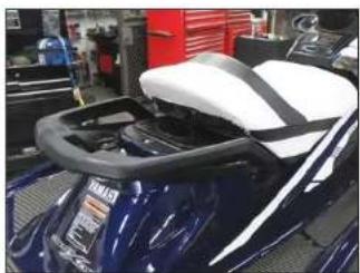
Close-up of a blue sports motorcycle with white backrest and black handle, no visible text or symbolsSTEP 1
Unlatch and remove the rear seat section from the vessel.
natural_image
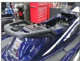
Close-up of a blue sports car interior with visible steering wheel and red equipment in the background (no text or symbols)STEP 2
Remove the front seat section from the vessel.
natural_image
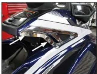
Close-up of a car's front bumper with white and silver trim, showing no visible text or symbolsSTEP 3
Remove the two indicated screws from the accent panel on the starboard side.
natural_image
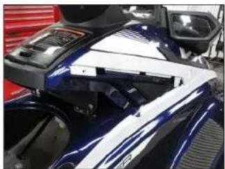
Close-up of a blue and white sports motorcycle with visible front-mounted equipment and red trim (no text or symbols)STEP 4
Remove the accent panel from the vessel.
natural_image
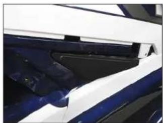
Close-up of a car's front and rear panels showing blue and white surfaces (no text or symbols visible)STEP 5
Carefully unclip and remove the screw cover panel.
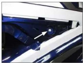
natural_image
Close-up of a car's front wheel assembly with a white arrow pointing to a blue component (no text or symbols visible)STEP 6
Remove the indicated screw.
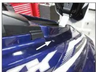
natural_image
Close-up of a blue car wheel rim with white stripes and a white arrow pointing to the edge (no text or symbols visible)STEP 7
Lift the lid. Remove the indicated bolt and the nut from the underside.
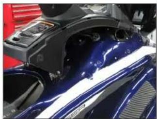
natural_image
Close-up of a blue sports motorcycle's front wheel and side gear assembly (no visible text or symbols)STEP 8
Remove the body panel from the vessel.
Page 3 • J. Audio, Inc., 2020 Continued on Next Page
natural_image
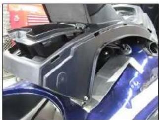
Close-up of a car body panel with visible structural ribs and mounting holes (no text or symbols)STEP 9
Open the storage compartment, and remove the insert.
Place the Amp Bracket on the vessel, as shown.
natural_image
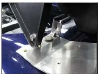
Close-up of a metal sewing machine needle stitching a blue and white surface (no visible text or symbols)STEP 10
Align the edges on the rear of the Amp Bracket with the edges of the factory bracket, as shown.
natural_image
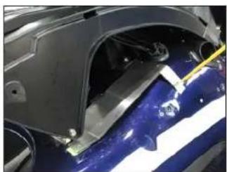
Close-up of a car's front wheel assembly with blue and white painted material, no visible text or symbolsSTE P 11
Mark the three Amp Bracket mounting hole locations, and remove the Amp Bracket.
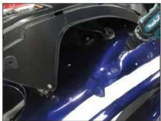
natural_image
Close-up of a car's front bumper area with blue glossy surface and white stripe, partially covered by a spray bottle (no visible text or symbols)STEP 12
Using a 1/4" drill bit, carefully drill through the three marks made in the previous step.
natural_image
Close-up of a black rectangular electronic device mounted on a metal frame, with wires and a small red-and-white component visible (no text or symbols)STEP 13
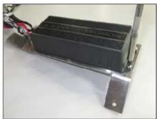
With the Amplifier oriented as shown, with the wiring toward the rear of the Amp Bracket, secure the Amplifier to the Amp Bracket using four #8 - 32 x 1/4" Phillips Pan Head Screws.
natural_image
Close-up of a car's front bumper with visible battery and wiring (no text or symbols)STEP 14
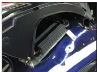
Place the Amp Bracket back into position. Pass a 1/4 - 20 x 1" Serrated Flange Bolt through each of the mounting holes in the Amp Bracket and holes drilled in Step 12.
From inside the hull, slide a 1/4" Oversized Flat Washer and 1/4" Nylon Locknut over each of the three 1/4 - 20 x 1" Serrated Flange Bolts, and firmly tighten.
natural_image
Close-up of a car's front wheel and rear windshield showing wiring and components (no visible text or symbols)STEP 15
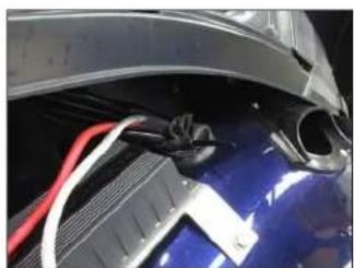
Loosen the factory cable tie in the grommet in front of the Amp Bracket. Pass the ring terminal end of the Power Harness through the grommet, leaving approximately 12" exposed, and tighten the cable tie.
natural_image
Close-up of a blue car hood with red and black hoses attached to its side (no visible text or symbols)STEP 16
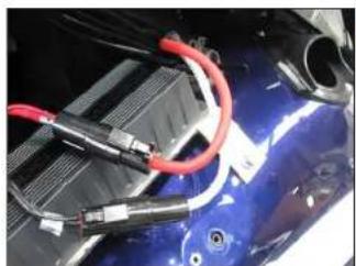
Connect the Power Harness to the Amplifier.
Page 4 • J. Audio, Inc., 2020 Continued on Next Page
natural_image
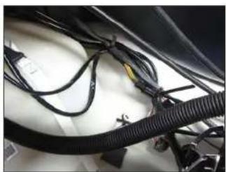
Close-up of automotive wiring harnesses and connectors (no visible text or symbols)STEP 17
Route the Power Harness down the starboard side of the vessel toward the battery, securing it with existing cable ties.
natural_image
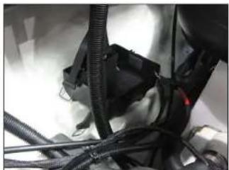
Close-up of automotive engine components including hoses and a valve assembly (no visible text or symbols)STEP 18
Disconnect the battery, and remove the battery from the battery tray.
natural_image
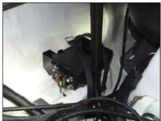
Close-up of a mechanical or electronic component with wires and connectors (no visible text or symbols)STEP 19
Align the Circuit Breaker with the battery tray, as shown, and mark the mounting hole locations.
Using a 1/4" drill bit, carefully drill through the marks.
natural_image
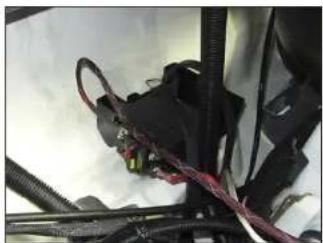
Close-up of a mechanical assembly with wires and components (no visible text or symbols)STEP 20
Securely mount the Circuit Breaker to the battery tray using a pair of 1/4 - 20 x 1" Hex Head Bolts with 1/4" Flat Washers from the inside of the tray and 1/4" Flat Washers and 1/4 - 20 Nylon Locknuts on the outside of the tray.
Press the red button on the Circuit Breaker to disengage it. Connect the positive power wire to one side and the 8 AWG extension to the other side.
Page 5 • J. Audio, Inc., 2020 Continued on Next Page
SLPK-YA-VXWR-SG INSTR_SKU#011494
natural_image
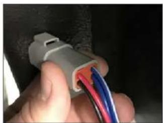
Close-up of a hand holding a white electrical connector with multicolored wires inserted (no visible text or symbols)STEP 21
Insert the wires from the MBT-CRXv2 into the 4-Pin Female Receptacle by sliding each pin into the rear of the connector, as shown. Pay close attention to the wire colors and corresponding pin locations, as listed below:
Pin 1 = Red Pin 4 = Blue/White
Pin 2 = Black Pin 3 = Blue
natural_image
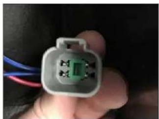
Close-up of a hand holding a gray electrical connector with visible pins and wiring (no text or symbols)STEP 22
Secure the pins by inserting the Wedgelock from the front of the 4-Pin Female Receptacle, as shown.
natural_image
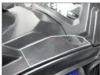
Close-up of a metallic car's side panel and dashboard (no visible text or symbols)STEP 23
Carefully cut Template A from the clear sheet on the indicated line. Align the Template A with the top of the upper panel, as shown, and mark the hole location. Remove Template A.
natural_image
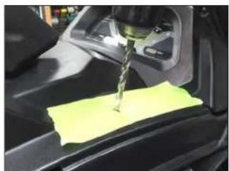
Close-up of a car interior with a yellow sticky note being inserted, no visible text or symbolsSTEP 24
Using a 1/4" drill bit, carefully drill a pilot hole through the mark made in the previous step.
natural_image
Close-up of a car's hood with a red spray bottle dispensing liquid onto the roof (no visible text or symbols)STEP 25
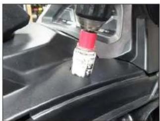
Using a 1-1/8" hole saw, enlarge the pilot hole drilled in the previous step.
natural_image
Close-up of a car's front wheel and dashboard with a circular vent component (no visible text or symbols)STEP 26
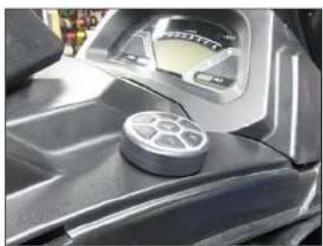
Add the thick round gasket to the MBT-CRXv2 controller, aligning the small hole in the gasket with the alignment pin on the back of the controller, and guide the controller's wiring through the hole drilled in the previous step.
From the underside, add the thin round gasket, then secure the MBT-CRXv2 using the threaded fastening collar. Reference the illustration in the MBT-CRXv2 owner's manual for details.
natural_image
Close-up of a car's front panel with visible wiring and connectors (no text or symbols)STEP 27
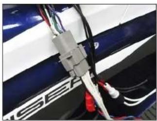
Connect the Amplifier Harness to the Amplifier. Using a utility knife, carefully cut the red and white protective caps from the Front Input jacks of the Amplifier Harness. Trim each cut flush with the plastic outer body of each RCA jack. Slide a piece of Heat Shrink Tubing over each channel of the RCA interconnects and connect to the Front Input jacks of the Amplifier Harness. Position the Heat Shrink Tubing over the joined connections, and use a heat or torch to shrink the tubing.
natural_image
Close-up of automotive electrical connectors and wiring on a blue car hood (no visible text or symbols)STEP 28
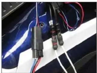
Connect the Amplifier Harness to the MBT-CRXv2 wiring. Slide a piece of Heat Shrink Tubing over each RCA interconnects, and plug the interconnects into the MBT-CRXv2 wiring. Using a heat gun or torch, shrink the Heat Shrink Tubing over the RCA connections.
Page 6 • JL Audio, Inc., 2020 Continued on Next Page
SLPK-YA-VXWR-SG INSTR_SKU#011494
natural_image
Close-up of a blue car's battery pack with exposed wiring and battery casing (no text or symbols visible)STEP 29
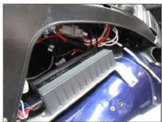
Secure the Amplifier Harness and Power Harness with the Marine Cable Ties, leaving access to the two speaker connectors.
Important: Do not position any Cable Ties within 2" of the connectors.
natural_image
Close-up of a blue car tire with white stripes being cleaned by a gloved hand (no visible text or symbols)STEP 30
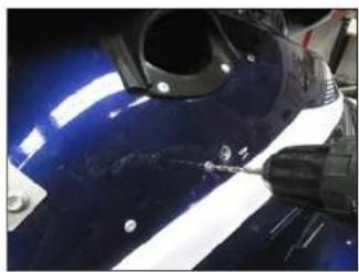
Locate the rivet below the induction tube. Use a center punch to tap in the center of the rivet, then carefully drill through the rivet head using a 1/8" drill bit.
Remove the factory threaded insert bracket from inside the hull.
natural_image
Close-up of a car's hood with blue and white stripes, showing mechanical components and glossy surfaces (no visible text or symbols)STEP 31
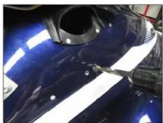
Using a 15/32" drill bit, enlarge the adjacent hole.
STEP 32
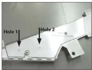
Remove the trim panel from the body panel removed in Step 8.
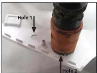
Carefully cut Template B from the clear sheet on the indicated line. Align Template B to the back of the trim panel, as shown, and mark the two hole locations. Remove Template B.
Using a 1/4" drill bit, carefully drill through the marks for Hole 1 and Hole 2.
STEP 33
Using a 1-5/8" hole saw, enlarge ONLY Hole 2.
STEP 34
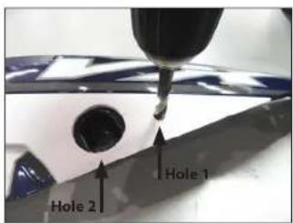
Reattach the trim panel to the body panel.
Using a 1/4" drill bit and Hole 1 as a guide, copy the location of Hole 1 onto the body panel.
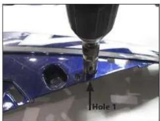
Remove the trim panel from the body panel. Using a 3/8" drill bit, enlarge Hole 1 in the trim panel.
STEP 35
Using a 3/4" hole saw, enlarge the copied Hole 1 in the body panel.
natural_image
Close-up of a blue car body with a black spray bottle inserted, showing no visible text or symbols.STEP 36
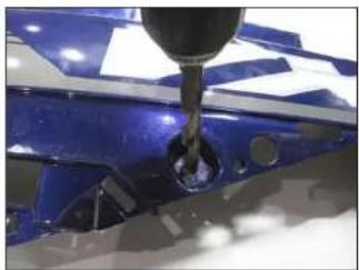
Using a 15/32" drill bit, enlarge the recessed factory hole.
natural_image
Close-up of a white robotic arm with a black cylindrical head and screw holes, held by a hand (no visible text or symbols)STEP 37
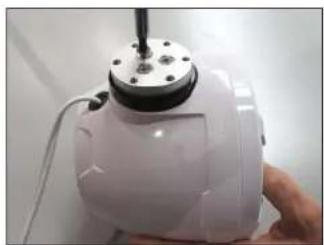
Align a Mounting Insert to the Speaker Enclosure, and secure using three M6 - 1 x 10mm Phillips Flat Head Screws.
natural_image
Close-up of a white ceramic teapot with a metallic handle and black screw, being held by a hand (no text or symbols visible)STEP 38
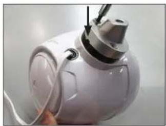
Align the Starboard Adaptor to the Mounting Insert installed in the previous step with the indicated notch facing opposite the speaker, and secure using three M6 - 1 x 10mm Phillips Flat Head Screws.
natural_image
Close-up of a white mechanical component with a circular hole and two small holes, no visible text or symbols.STEP 39
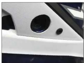
Install a Rubber Grommet into Hole 1 in the trim panel, and reattach the trim panel to the body panel.
natural_image
Close-up of a white helmet with a blue and white emblem, partially visible against a plain background (no text or symbols)STEP 40
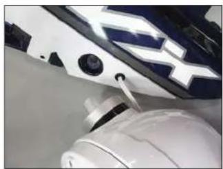
Pass the speaker cable exiting the Speaker Enclosure through the Rubber Grommet, as shown, and align the Starboard Adaptor on the Speaker Enclosure with the Hole 2 in the trim panel.
Page 7 • J. Audio, Inc., 2020 Continued on Next Page
natural_image
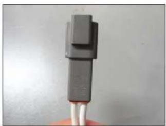
Close-up of a black plastic electrical connector with a white cable, held by a hand (no text or symbols visible)STEP 41
Insert the speaker cable from the Speaker Enclosure into the 2-Pin Female Receptacle by sliding each pin into the rear of the connector, as shown. Pay close attention to the wire colors and pin locations, as listed below:
Pin 1 = White with (+)
Pin 2 = White
natural_image
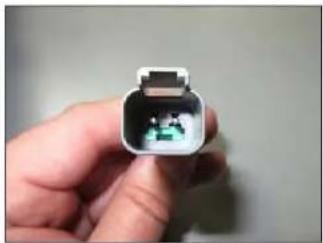
Close-up of a hand holding an open white connector with a small green symbol inside (no text or labels visible)STEP 42
Secure the pins by inserting the Wedgelock from the front of the 2-Pin Female Receptacle, as shown.
natural_image
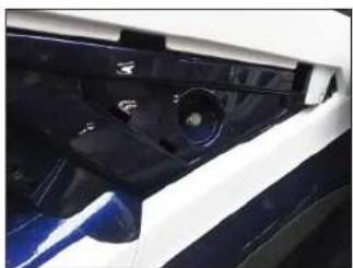
Close-up of a car interior showing dashboard and rearview mirror (no visible text or symbols)STEP 43
Reinstall the body panel onto the vessel, and hand tighten the screw removed in Step 6.
natural_image
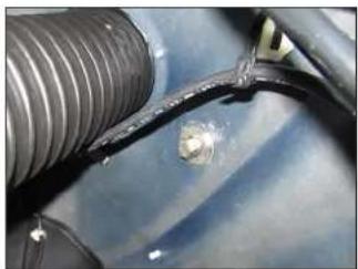
Close-up of a car engine component with visible wiring and a small sensor (no text or symbols)STEP 44
Slide a 7/16" Flat Washer and 7/16" Split Lock Washer over a 7/16 - 14 x 1-1/4" Hex Head Bolt. From inside the hull, pass the assembly through the hole drilled in Step 29, thread the 7/16 - 14 x 1-1/4" Hex Head Bolt into the Starboard Adaptor on the Speaker Enclosure, and hand tighten.
Page 8 • JL Audio, Inc., 2020 Continued on Next Page
SLPK-YA-VXWR-SG INSTR_SKU#011494
natural_image
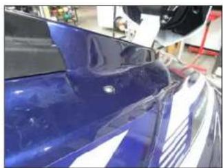
Close-up of a blue car's front bumper with glossy paint and white highlights, partially covered by red equipment (no visible text or symbols)STEP 45
Reinstall the bolt and nut removed in Step 7.
natural_image
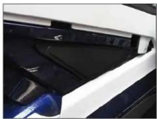
Close-up of a car's front and side panels showing blue and black surfaces (no text or symbols visible)STEP 46
Fully tighten the screw reinstalled in Step 41, and reinstall the screw cover panel.
natural_image
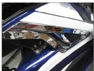
Close-up of a car's front wheel and dashboard with reflective highlights (no visible text or symbols)STEP 47
Reinstall the accent panel and the two screws removed in Step 3, and fully tighten.

natural_image
Close-up of a metallic wheel component with a star-shaped hub, mounted on a reflective surface (no visible text or symbols)STEP 48
Remove the six #8 x 1-1/4" Pan Head Screws and #8 Flat Washers, rotate the speaker to the desired angle, and reinstall.
natural_image
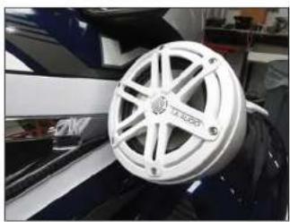
Close-up of a white industrial component with a circular spool, mounted on a dark surface (no visible text or symbols)STEP 49
Remove the adhesive backing from the JL Audio Logo Sport Grille Badge, and install the badge onto the speaker grille.
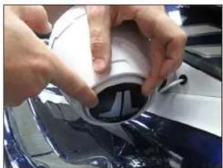
natural_image
Close-up of hands installing a white plastic component on a blue surface (no visible text or symbols)STEP 50
Remove the adhesive backing from the Rear Logo Appliqué. With the logo positioned at the desired angle, attach the Rear Logo Appliqué, gently pressing on the center to remove any air pockets.
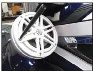
natural_image
Close-up of a white and blue car wheel with a black tab, mounted on a glossy surface (no visible text or symbols)STEP 51
Repeat Steps 28-48 for the port side.
natural_image
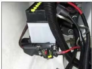
Close-up of a mechanical or electrical component with wires, connectors, and a white sheet (no visible text or symbols)STEP 52
Reinstall the battery. Connect the ground cable from the Power Harness to the negative battery terminal and the power cable from the Circuit Breaker to the positive battery terminal.
Page 9 • J. Audio, Inc., 2020
SLPK-YA-VXWR-SG INSTR_SKU#011494
natural_image
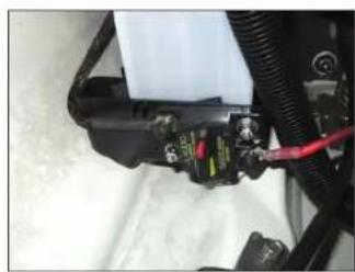
Close-up of a mechanical assembly with black components and red wires, no visible text or symbolsSTEP 53
Press in on the yellow arm of the Circuit Breaker to engage it.

natural_image
Blue and white sports jet on a wheeled platform in a workshop setting (no visible text or symbols)STEP 54
Reinstall the insert into the storage pocket, and reinstall both seat sections.
Refer to the MBT-CRXv2 owner's manual to pair your mobile device.
CONGRATULATIONS!
You have completed the installation for this model! Enjoy your new SlamPak™!
SPECIFICATIONS
SPEAKERS
Continuous Power Handling (RMS): 60 watts
Nominal Impedance: 4 ohms
Frequency Response: 100 Hz - 25 kHz - / 3 dB
JLAUDIO. How we play.*
| (954) 443-1100 | www.jlaudio.com |
| All social behaviors are obvious, to change without risks. A, false, and other non-pair* are registered in terms of A, false, Inc. (strongly the fact that and no response to this information is available).b=2080, false, Inc. - for more detailed information please call us online at www.jlaudio.com. | |
JLA-SKU# 011494 - ver. 07.15.2020 · 10362 NORTH COMMERCIPANWAY · MIHAMAR, -TORIDA · 33075 · USA
1
"011494"


- ! IMPORTANT
- INCLUDED HARDWARE
- STEP 17
- STEP 18
- STEP 19
- STEP 20
- STEP 21
- STEP 22
- STEP 23
- STEP 24
- STEP 25
- STEP 26
- STEP 27
- STEP 28
- STEP 29
- STEP 30
- STEP 31
- STEP 32
- STEP 41
- STEP 42
- STEP 43
- STEP 44
- STEP 45
- STEP 46
- STEP 47
- STEP 48
- STEP 49
- STEP 50
- STEP 51
- STEP 52
- STEP 53
- STEP 54
- CONGRATULATIONS!
- SPECIFICATIONS
- SPEAKERS
Brand : JL Audio
Model : SlamPak SLPK-YA-VXWR-SG-WH
Category : Pregnant