
RA108CR - Râteau agricole KUBOTA - Free user manual and instructions
Find the device manual for free RA108CR KUBOTA in PDF.


| Product Type | Radio Receiver |
| Model | RA108CR |
| Brand | Kubota |
| Dimensions (W x H x D) | 200 mm x 150 mm x 100 mm |
| Weight | 1.5 kg |
| Power Supply | AC 100-240V, 50/60 Hz, or 6 x D batteries |
| Frequency Range | FM 87.5-108 MHz, AM 530-1710 kHz |
| Number of Presets | 30 stations |
| Audio Output | 3W RMS |
| Speaker Size | 3 inches |
| Headphone Jack | 3.5 mm stereo |
| Antenna | FM telescopic, AM built-in ferrite |
| Display | LCD with backlight |
| Additional Features | Alarm clock, sleep timer, snooze, calendar |
| Maintenance | Clean with dry cloth, avoid solvents |
| Safety | Keep away from water, use only recommended power sources |
| Spare Parts | Replacement power cords, batteries, antennas available |
| Repairability | Serviceable by qualified technician for internal issues |
| General Information | Manual available in PDF, 49 pages |
Frequently Asked Questions - RA108CR KUBOTA
User questions about RA108CR KUBOTA
0 question about this device. Answer the ones you know or ask your own.
Ask a new question about this device
Download the instructions for your Râteau agricole in PDF format for free! Find your manual RA108CR - KUBOTA and take your electronic device back in hand. On this page are published all the documents necessary for the use of your device. RA108CR by KUBOTA.
USER MANUAL RA108CR KUBOTA
natural_image
Technical line drawing of a tracked agricultural machine with multiple blades and a central wheel (no text or symbols)38863
Kubota®

512-069MK
Operator Manual
Read the operator manual entirely. When you see this symbol, the subsequent instructions and warnings are serious - follow without exception. Your life and the lives of others depend on it! Illustrations may show optional equipment not supplied with standard unit.
■ Machine Identification
Record your machine details in the log below. If you replace this manual, be sure to transfer this information to the new manual.
If you, or the dealer, have added Options not originally ordered with the machine, or removed Options that were originally ordered, the weights and measurements are no longer accurate for your machine. Update the record by adding the machine weight and measurements on page 36 with the Option(s) weight and measurements.
| Model Number | |
| Serial Number | |
| Machine Height | |
| Machine Length | |
| Machine Width | |
| Machine Weight | |
| Year of Construction | |
| Delivery Date | |
| First Operation | |
| Accessories |
Dealer Contact Information
Name:
Street:
City/State:
Telephone:
Email:
Dealer's Customer No.:
CALIFORNIA PROPOSITION 65 WARNING
WARNING: This machine contains components and/or fluids known to the State of California to cause cancer and birth defects or other reproductive harm. (California law requires this warning to be given to customers in the State of California.)
For more information: oehha.ca.gov/proposition-65
Table of Contents
Introduction....1
Further Assistance....1
Safety Information 2
Safety Decals 6
Safety Reflectors and Decals 6
Preparation and Setup ....10
Operator Manual Storage 10
Initial/Seasonal Setup....10
Hitching and Unhitching the Rake 11
Initial Hitch Clevis Height Adjustment....11
Hitching the Tractor To the Hay Rake....12
Unhitching the Tractor From the Hay Rake......13
Operating Instructions ....14
Pre-Use Checklist....14
Lockout Valves 15
Raising and Lowering the Wings....15
Raising 15
Lowering....15
Roading the Hay Rake 16
Roading Checklist ....16
Roading 16
Raking with Both Wings....17
Raking with One Wing....18
Kicker Operation (Option)....19
Single Kicker Wheel (Option) 19
Dual Kicker Wheels (Option)....19
Parking 20
Storage 20
Adjustments and Installations....21
Leveling the Rake Wheels....21
Adjusting Windrow and Raking Widths.....21
Wing Angle Setting....21
Wing Spread Setting 21
Windrow Widths and Raking Widths Chart ......22
Adjusting the Wing Angle 23
Adjusting the Wing Spread....24
Adjusting Individual Rake Wheel Down Pressure .....25
Adjusting Wing Down Pressure....26
Troubleshooting 27
Maintenance and Lubrication....28
Maintenance....28
Bleeding the Hydraulic System 29
Rake Wheel Removal and Installation ....30
Removal 30
Installation....30
Rake Wheel Hub Removal and Installation....31
Removal 31
Disassembly and Assembly 31
Installation....31
Transport Wheel Removal and Installation ....32
Removal 32
Installation....32
Lubrication....33
Options....34
Appendix - Reference Information....36
Specifications 36
Torque Values Chart 37
Tire and Wheel Information....37
Hydraulic Connectors and Torque....38
Hydraulic Diagrams 39
Wiring Diagram....41
Introduction
The RA108CR, RA110CR, RA210CR, RA212CR Hay Rakes are cart style hay rakes for making crop windrows. The hay rake uses a series of rake wheels to funnel material into a single windrow.
The hay rake has steel rake wheels which are suitable for most conditions. Optional wind screens can be installed on the rake wheels to reduce the effect of wind on the crop being raked.
The hay rake can be optionally equipped with single or dual kicker wheels. The kicker wheels move the crop from the center of the hay rake that would otherwise not be turned.
An optional lighting kit can be ordered on the hay rake, or added later.
Hay Rake Models Covered Document Family
| RA108CR 8 Wheel Hay Rake |
| RA110CR 10 Wheel Hay Rake |
| RA210CR 10 Wheel Hay Rake |
| RA212CR 12 Wheel Hay Rake |
Owner Assistance
If you need customer service or repair parts, contact a Kubota dealer. They have trained personnel, repair parts and equipment specially designed for Kubota products.
Your machine's parts were specially designed and should only be replaced with Kubota parts. Always use the serial and model number when ordering parts from your Kubota dealer. The serial number plate is located on the left-hand side of the mainframe.

natural_image
Mechanical assembly diagram showing a bracket with attached components and an arrow indicating direction (no text or symbols)Figure 2 Serial Number Plate Location
Record your rake model and serial number on the inside cover of this manual for quick reference.

Kubota QRC
The QR Code (Quick Response) to the left will take you to the Kubota web page. Use your smart phone or tablet to scan the QR Code with an appropriate app to begin viewing.

Figure 1 Rake Orientation
| 512-069MK Current Document Name (this document) |
| 512-069PK Parts Manual |
| 512-069QK Pre-delivery Manual |
| 512-072MK Installation Instructions |
Further Assistance
Kubota and your Kubota dealer want you to get the most out of your machine. When in need of parts or major service, see your local Kubota dealer. For service, contact the Kubota dealership from which you purchased your machine or your local Kubota dealer. When in need of parts, have your machine serial number readily available.
To locate a North American Kubota dealer, go online at www.kubota.com/locator or use the QRC code at the bottom of this page to find a dealer near you.
This machine is warranted under Kubota's Express Limited Warranty. A copy of this warranty may be obtained from your dealer. No warranty shall, however, apply if the machine has not been handled according to the instruction given in the operator's manual.

Dealer QRC
The QR Code (Quick Reference) to the left will take you to available dealers for Kubota products. Refer to the Kubota QRC locater for detailed instructions to begin viewing.
Safety Information
■ Look for Safety Symbol

The SAFETY ALERT SYMBOL indicates there is a potential hazard to personal safety involved and extra safety precaution must be taken. When you see this symbol, be alert and carefully read the message that follows it. In addition to design and configuration of equipment, hazard control and accident prevention are dependent upon the awareness, concern, prudence and proper training of personnel involved in the operation, transport, maintenance and storage of equipment.
■ Be Aware of Signal Words
Signal words designate a degree or level of hazard seriousness. The signal words are:
DANGER
DANGER Indicates an imminent hazard which, if not avoided, will result in death or serious injury. This signal word is limited to the most extreme situations, typically for machine components that, for functional purposes, cannot be guarded.
WARNING
WARNING Indicates a potential hazard which, if not avoided, could result in death or serious injury, and includes hazards that are exposed when guards are removed. It may also be used to alert against unsafe practices.
CAUTION
CAUTION Indicates a potential hazard which, if not avoided, may result in minor or moderate injury. It may also be used to alert against unsafe practices.
NOTICE
NOTICE Indicates that equipment or property damage could result if instructions are not followed.
Useful information related to the preceding topic.
■ Prepare for Emergencies

000
112
911
999


- Be prepared if a fire starts.
- Keep a first aid kit and fire extinguisher handy.
- Keep emergency numbers for doctor, ambulance, hospital and fire department near phone.
■ Be Familiar with Safety Decals

natural_image
Silhouette of a person reading a book with three other icons on the sides (no text or symbols)- Throughly read and understand "Safety Decals" on page 6.
- Read all instructions noted on the decals.
- Keep decals clean. Replace damaged, faded and illegible decals.
■ Wear Protective Equipment

natural_image
Silhouette of a hand holding a folder next to a circular tray (no text or symbols)

- Wear protective clothing and equipment appropriate for the job, such as safety shoes, safety glasses, hard hat, and ear plugs.
- Clothing must fit snug without fringes and pull strings to avoid entanglement with moving parts.
- Prolonged exposure to loud noise can cause hearing impairment or hearing loss. Wear suitable hearing protection such as earmuffs or earplugs.
- Operating equipment safely requires your full attention. Avoid wearing entertainment headphones while operating machinery.
■ Use A Safety Chain

natural_image
Silhouette of a mechanical linkage with chains and a handle (no text or symbols)- A safety chain will help control drawn machinery if the machinery separates from tractor drawbar.
- Use a chain with a strength rating equal to or greater than the gross weight of towed machinery.
- Attach chain to tractor drawbar support or other specified anchor location. Allow only enough slack in chain to permit turning.
- Replace chain if any links or end fittings are broken, stretched or damaged.
- Do not use safety chain for towing.
■ Avoid High Pressure Fluids

natural_image
Silhouette of a human head with an arrow pointing to the nose (no text or symbols)
natural_image
Silhouette of a hand gripping a cylindrical object, no text or symbols presentNOTE
Escaping fluid under pressure can penetrate the skin, causing serious injury.
- Make sure all hydraulic fluid connections are tight and all hydraulic hoses and lines are in good condition before applying pressure to the system.
- Avoid the hazard by relieving pressure before disconnecting hydraulic lines or performing any work on the system.
- Wear protective gloves and safety glasses or goggles when working with hydraulic systems.
- Escaping fluid under pressure can penetrate the skin causing serious injury.
-
Use a piece of paper or cardboard, NOT BODY PARTS, to check for suspected leaks.
-
DO NOT DELAY. If an accident occurs, seek immediate medical assistance from a physician familiar with this type of injury. Any fluid injected into the skin or eyes must be treated within a few hours or gangrene can result.
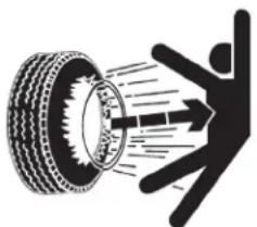
■ Tire Safety
natural_image
Silhouette of a person pushing a tire with motion lines indicating speed or impact (no text or symbols)NOTE
Tire changing can be dangerous and must be performed by trained personnel using correct tools and equipment.
- When inflating tires, use a clip-on chuck and extension hose long enough for you to stand to one side—not in front of or over tire assembly. Use a safety cage if available.
- When removing and installing wheels, use wheel-handling equipment adequate for weight involved.
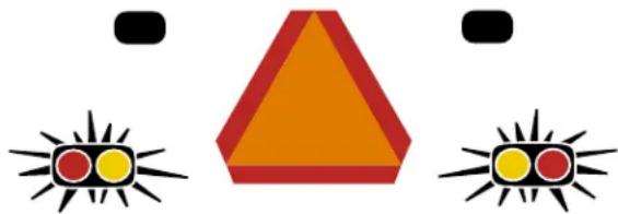
■ Use Safety Lights and Devices
natural_image
Simple diagram with three triangular shapes and red/yellow circular elements, no text or symbols present.NOTE
Slow-moving tractors and towed machinery can create a hazard when driven on public roads. They are difficult to see, especially at night.
- If the slow moving vehicle sign obscures the lighting on the tractor, install the optional lighting kit on the implement.
- If equipped, use flashing warning lights and turn signals whenever driving on public roads.
- Use safety devices provided with implement.
■ Keep Riders Off Machinery

natural_image
Silhouette illustration of a person riding a car with a person inside, no text or symbols present
NOTE
Riders obstruct the operator's view. Riders could be struck by foreign objects or thrown from the machine.
- Never carry riders or use machinery as a personal lift.
- Riders obstruct the operators view.
- Riders can be struck by foreign objects or thrown from the machine
- Never allow children to operate equipment.
- Keep all bystanders away from machine during operation.
■ Transport Machinery Safely


NOTE
Maximum Transport speed for implement is 40 kph (25 mph). Some rough terrains require a slower speed. Sudden braking can cause a towed load to swerve and upset.
- Comply with state and local laws.
- Do not exceed 40 kph (25 mph). Never travel at a speed that does not allow adequate control of steering and stopping. Some rough terrains require a slower speed.
-
Use caution when maneuvering with one or both wings folded up. Do not exceed 8 kph (5 mph) in turns. Steep inclines or sharp turns can cause the hay rake to turn over. Tipping can result in injury or equipment damage.
-
Carry reflectors or flags to mark machinery in case of breakdown on the road.
- Keep clear of overhead power lines and other obstructions when transporting. Refer to transport dimensions under see "Appendix - Reference Information" on page 36.
- Do not tow an implement that, when fully loaded, weighs more than 1.5 times the weight of towing vehicle.
- Turning tractor too tight can cause implement to tip over.
- When towing on a trailer, secure implement with tie downs and chains.
- When towing on a trailer, sudden braking can cause a trailer to swerve and upset. Reduce speed if trailer is not equipped with brakes.
■ Shutdown and Storage
- Park the tractor and implement on a solid, level surface where children normally do not play.
- Raise the wings, put tractor in park or set park brake. Turn off engine and remove switch key to prevent unauthorized starting.
- Wait for all components to come to a complete stop before leaving the operator's seat.
- Put both lockout valves in the locked position to prevent the wings from lowering.
- Unhitch the tractor. Secure the implement using blocks and supports.
■ Use Seat Belt and ROPS
- KUBOTA recommends the use of a CAB or Roll Over Protective Structure (ROPS) and seat belt in almost all applications. This combination will reduce the risk of serious injury or death, should the tractor be upset.
- If the tractor is equipped with a foldable ROPS it may be temporarily folded down only when absolutely necessary for areas with height constraints. (There is no operator protection provided by the ROPS in the folded position. For operator safety the ROPS should be placed in the upright and locked position and the seat belt fastened for all other operations.)
- Always use the seat belt if the tractor has a CAB or ROPS. Do not use the seat belt if a foldable ROPS is down or there is no ROPS. Check the seat belt regularly and replace if frayed or damaged.
■ Practice Safe Maintenance
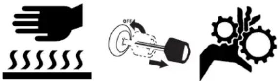
- Understand procedure before doing work. Use proper tools and equipment. Refer to this manual.
- Work in a clean, dry area.
- Lower the implement. Put tractor in Park, turn off engine. To prevent unauthorized starting, remove key before performing maintenance or service work.
- If work must be performed with wings raised, put both lockout valves in the locked position.
- Make sure all moving parts have stopped and all system pressure is relieved.
- Disconnect lighting harness from the tractor before servicing or adjusting electrical systems.
- Welding: Disconnect lighting harness from the tractor. Protect hydraulic lines. Avoid fumes from heated paint.
- Inspect all parts. Make sure parts are in good condition and installed properly. Replace parts on this machine with genuine Kubota parts only.
- Do not alter this machine in a way which will adversely affect its performance.
- Remove buildup of grease, oil or debris.
- Remove all tools and unused parts from implement before operation.
■ Safety At All Times

NOTE
Thoroughly read and understand the instructions in this manual before operation. Read all instructions noted on the safety decals.
NOTE
Do not allow anyone to operate this equipment who has not fully read and comprehended this manual and who has not been properly trained in the safe operation of the equipment.
-
The operator must not use drugs or alcohol as they can change the alertness or coordination of that person while operating equipment. If over-the-counter drugs are used, seek medical advice on whether you can safely operate equipment.
-
Operator must be familiar with all functions of the tractor and attachments, and be able to handle emergencies quickly.
- Make sure all guards and shields are in place and secured before operating the implement.
- Keep all bystanders away from equipment and work area.
- Operator must start tractor and operate controls from the driver's seat only, never from the ground.
- Dismounting from a moving tractor can cause serious injury or death.
- Be familiar with all functions of the implement.
- Do not leave implement unattended with tractor engine running.
- Do not stand between the tractor and the implement during hitching.
- Watch out for wires, trees, etc., when folding and raising the implement.
- Turning tractor too tight can cause hitched implement to ride up on wheels. This can result in injury or equipment damage.
- Use caution when maneuvering with one or both wings folded up. Do not exceed 8 kph (5 mph) in turns. Steep inclines or sharp turns can cause the hay rake to tip over. Tipping can result in injury or equipment damage.
Safety Decals
Safety Reflectors and Decals
Your implement comes equipped with all safety reflectors and decals in place. They were designed to help you safely operate your implement.
▲ Read and follow decal directions.
▲ Keep lights in operating condition.
▲ Keep all safety decals clean and legible.
▲ Replace all damaged or missing decals. Order new decals from your Kubota dealer. Refer to this section for proper decal placement.
▲ When ordering new parts or components, also request corresponding safety decals.
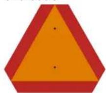
Slow Moving Vehicle Reflector
818-055C
natural_image
Simple geometric shape with orange triangle and red border (no text or symbols)On the back of mainframe, in center; 1 total
Installing new decals:
- Clean the area on which the decal is to be placed.
- Peel backing from decal. Press firmly on surface, being careful not to cause air bubbles under decal.

natural_image
Technical line drawing of a mechanical assembly with wheels and a directional arrow (no text or symbols)Red Reflectors
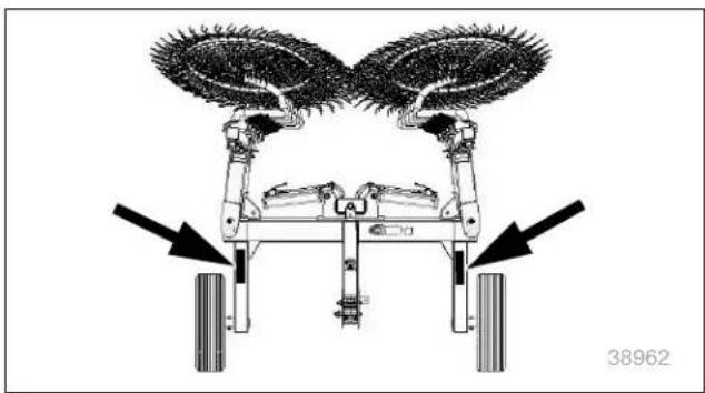
838-614C

natural_image
Solid red rectangular shape with rounded corners (no text or symbols)On rear face of both wheel struts; 2 total
natural_image
Diagram of a robotic vehicle with two large brush heads and two wheels, showing no text or symbols.Amber Reflectors 838-615C

natural_image
Solid orange rectangular shape with rounded corners (no text or symbols)On front face of the wheel struts, On the bottom of the wing struts; 4 total

natural_image
Technical line drawing of a mechanical vehicle with a wheel and attached components, showing no text or symbols.
Warning: Excessive Speed Hazard 858-850C

On top of tongue; 1 total

natural_image
Technical line drawing of a mechanical assembly with an arrow pointing to a component (no text or symbols present)Warning: High Pressure Fluid Hazard 818-437C

Top tongue; 1 total

Warning: Read Manual (in Spanish):
858-849C

Advising non-English readers to seek translation On top of tongue;
1 total
Warning: General Instruction 858-840C

On top of tongue; 1 total
Warning: Pinch Point Hazard 818-589C

On top of mainframe; 2 total

natural_image
Technical line drawing of a mechanical assembly with an arrow pointing to a component (no text or symbols present)
natural_image
Technical line drawing of a mechanical assembly with an arrow pointing to a component (no text or symbols present)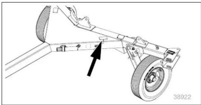
natural_image
Technical line drawing of a mechanical vehicle with a highlighted component and arrow indicator (no text or symbols)Warning: Pinching or Shearing Hazard 818-491C

On top of wing arms; 2 total
Warning: Tire Pressure and Torque 848-021C

On outside of each wheel; 2 total

natural_image
Technical line drawing of a mechanical assembly with a tire and attached components (no text or symbols)
natural_image
Technical line drawing of a mechanical assembly with a tire and mounting bracket (no text or symbols)Preparation and Setup
This section helps you prepare your tractor and hay rake for use, and covers tasks that need to be done seasonally, or when the tractor/hay rake configuration changes.
Before using the hay rake in the field, you must hitch it to a suitable tractor, inspect systems, and level the hay rake. Before using the hay rake for the first time, and periodically thereafter, certain adjustments are required.
Operator Manual Storage
Refer to Figure 3
The manual holder is located on the left-hand side of the mainframe.
Initial/Seasonal Setup
Complete this checklist at initial delivery, when using a different tractor, and seasonally. Check, and as necessary, complete these items before continuing to the routine setup items:
☐ Remove grease from exposed cylinder rods, if so protected at last storage.
☐ See "Safety At All Times" on page 5. Read and understand all items.
☐ Check that all working parts are moving freely, bolts are tight, and cotter pins are spread.
☐ Check that all grease fittings are in place and lubricated. See "Lubrication" on page 33.
☐ Check that all safety decals and reflectors are correctly located and legible. Replace if damaged. See "Safety Decals" on page 6.
☐ Inflate tires to pressure recommended and tighten wheel bolts as specified. See “Tire and Wheel Information Chart” on page 37.
☐ Make sure the wings are level. See “Leveling the Rake Wheels” on page 21.

natural_image
Technical line drawing of a mechanical vehicle with wheels and a bracket, showing no text or symbolsFigure 3 Manual Holder
Hitching and Unhitching the Rake
Initial Hitch Clevis Height Adjustment
Refer to Figure 4
Measure the distance from the top of tractor drawbar to the ground. See the illustration to determine if the hitch clevis is in the correct mounting position.
NOTICE
Do not adjust hitch clevis height with parking jack. Using parking jack to adjust hitch clevis height can cause the rake wheels to not be at the correct height.
If adjustment of the hitch clevis is necessary, do the following;
a. Remove lock nuts and bolts.
b. Measure the height of the tractor drawbar
c. Move hitch clevis (2) up or down until opening in the hitch clevis is at the correct height. The hitch clevis can also be turned over to change the adjustment.
d. Install the two bolts.
e. Install the safety chain and then the safety chain washer and a flanged lock nut on the top bolt.
f. Install a flanged lock nut on the bottom bolt.
g. Tighten the flanged lock nuts to 340 N m (265 lb-ft).
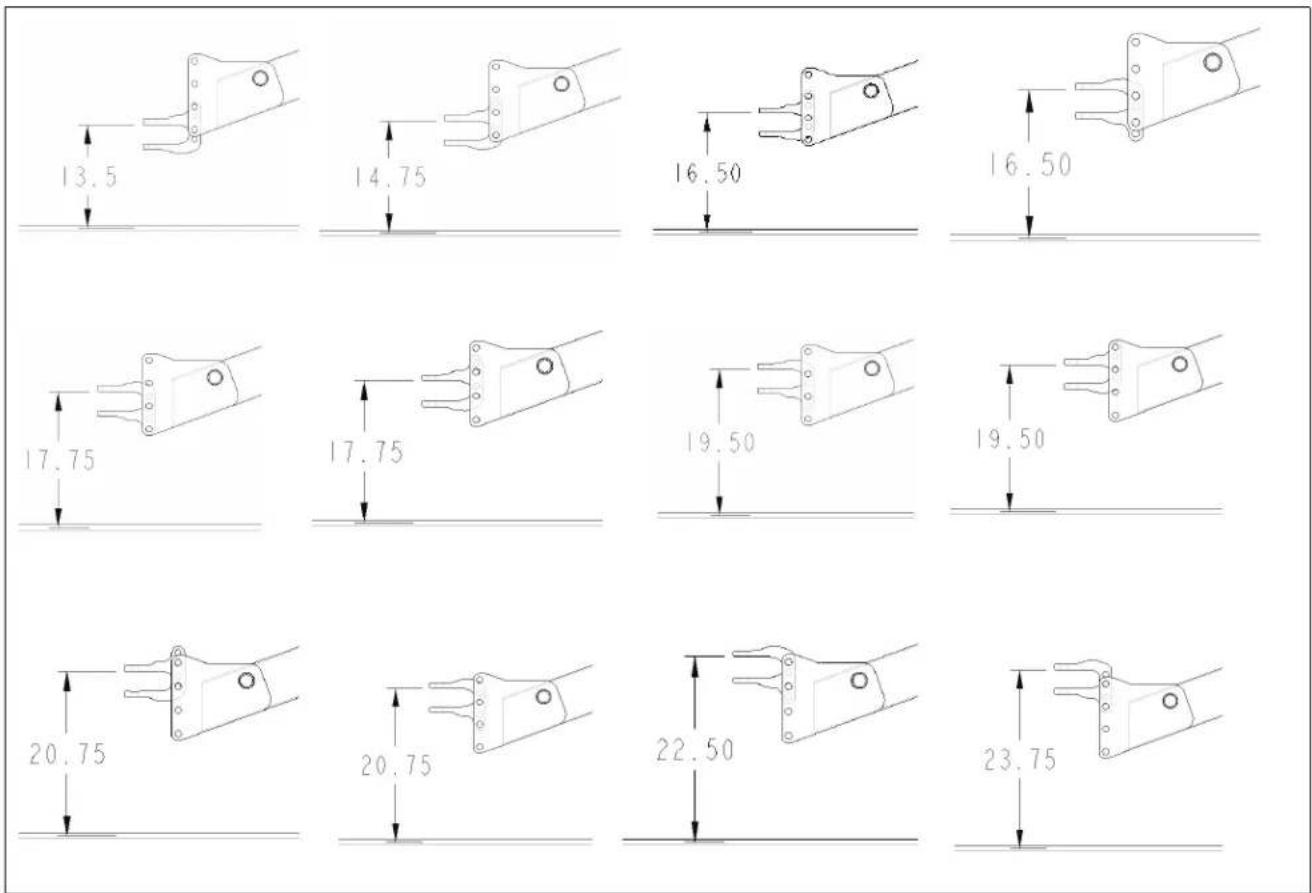
Figure 4
Hitch Clevis Height Adjustment
38923
Hitching the Tractor To the Hay Rake
Refer to Figure 5
- Make sure the parking jack (1) is properly attached to the side of the tongue (2). The parking jack must be secured with the detent pin (3).
NOTICE
Detent pin must be fully inserted and secured in the parking jack before working on or around the hay rake.
- Put blocks in front of and behind the cart wheels.
- Store the tractor's upper center 3-point link in the storage hook.
- Start tractor and raise 3-point lift arms all the way up.
- Carefully back tractor within close proximity of the hitch clevis (4).
- Apply the tractor parking brake. Stop the tractor engine and take the key with you to prevent unauthorized starting.
- Check the alignment of the hitch clevis and the tractor drawbar. If the alignment is not correct, See "Initial Hitch Clevis Height Adjustment" on page 11 and adjust the hitch clevis.
NOTICE
Do not adjust hitch clevis height with parking jack. Using parking jack to adjust hitch clevis height can cause the rake wheels to not be at the correct height.
- Start the tractor. Continue to back the tractor toward the hay rake until hole in tractor drawbar and holes in hitch clevis hitch are aligned.
- Apply the tractor parking brake. Stop the tractor engine and take the key with you to prevent unauthorized starting.
The hitch pin and the hitch pin keeper are customer supplied. - Attach the hitch clevis to tractor drawbar by inserting customer supplied hitch pin.
- Secure hitch pin with customer supplied hitch pin keeper.
- Attach hitch safety chain to the tractor drawbar support. Adjust chain length to remove all slack except what is necessary to permit turning. Lock chain hook securely to the safety chain.
- Connect hydraulic hoses to the tractor.
- If equipped, connect the lighting harness to the tractor.
- Raise the parking jack until hitch weight is supported by tractor drawbar.
- Remove detent pin and then remove the parking jack from the mounting tube on the side of the tongue.

Figure 5 Parking Jack in Parking Position
38950
DANGER
Crushing Hazard:
Do not stand or place any body part between hay rake and moving tractor. You may be severely injured or killed by being crushed between the tractor and hay rake. Do not operate hydraulic 3-point lift controls while someone is directly behind the tractor or near the implement. Stop tractor engine and set parking brake before attaching harnesses and hoses.
DANGER
High Pressure Fluid Hazard:
Check all hydraulic lines and fittings before applying pressure. Relieve pressure before disconnecting hydraulic lines. Wear protective gloves and safety glasses or goggles when working with hydraulic systems. Fluid escaping from a very small hole can be almost invisible. Use paper or cardboard, NOT BODY PARTS, to check for leaks. Escaping fluid under pressure can have sufficient pressure to penetrate the skin causing serious injury. If hydraulic fluid is injected into the skin or eyes, seek immediate medical assistance from a physician familiar with this type of injury. Within a few hours gangrene can start to develop. DO NOT DELAY. Only trained personnel should work on system hydraulics.
Refer to Figure 6
- Attach parking jack (1) to the storage mount on top of the tongue (2). The parking jack must be parallel with the tongue. Install the detent pin (3).
- Remove blocks from in front of and behind the wheels.
- If the wings are lowered, raise the wings for roading. See "Raising and Lowering the Wings" on page 15
Unhitching the Tractor From the Hay Rake
- Park tractor and hay rake on a solid, level surface.
If necessary, make sure there is room to lower the wings. - Raise the wings and, if equipped, the kicker wheel(s).
- Apply the tractor parking brake. Stop the tractor engine and take the key with you to prevent unauthorized starting.
- Move hydraulic control lever back and forth several times to release all hydraulic pressure.
- Place blocks in front and behind the transport tires.
- Remove detent pin from the parking jack. Remove the parking jack from the storage mount on top of the tongue.
Refer to Figure 7
- Install the parking jack (1) to the mount on the side of the tongue (2). Make sure the parking jack is mounted vertically. Install the detent pin (3).
- Raise the parking jack until the weight of the hitch clevis (4) is off the tractor drawbar.
- Disconnect hydraulic hoses from the tractor. Store quick disconnect couplers in the slots on the tongue.
- Disconnect the lighting harness from the tractor. Install the connector for the lighting harness in the connector holder on the tongue.
- Remove the hitch pin keeper and the hitch pin.
- Start tractor and drive forward several feet.
- Apply the tractor parking brake. Stop the tractor engine and take the key with you to prevent unauthorized starting.
- Install the hitch pin and hitch pin keeper in the hitch clevis for storage.
- At the rear of the hay rake, put all hydraulic lockout valves in the locked position.

Figure 6 Parking Jack in Storage Position
DANGER
Crushing Hazard:
Do not stand or place any body part between hay rake and moving tractor. You may be severely injured or killed by being crushed between the tractor and hay rake. Do not operate hydraulic 3-point lift controls while someone is directly behind the tractor or near the implement. Stop tractor engine and set parking brake before attaching harnesses and hoses.
DANGER
High Pressure Fluid Hazard:
Check all hydraulic lines and fittings before applying pressure. Relieve pressure before disconnecting hydraulic lines. Wear protective gloves and safety glasses or goggles when working with hydraulic systems. Fluid escaping from a very small hole can be almost invisible. Use paper or cardboard, NOT BODY PARTS, to check for leaks. Escaping fluid under pressure can have sufficient pressure to penetrate the skin causing serious injury. If hydraulic fluid is injected into the skin or eyes, seek immediate medical assistance from a physician familiar with this type of injury. Within a few hours gangrene can start to develop. DO NOT DELAY. Only trained personnel should work on system hydraulics.

Figure 7 Parking Jack in Parking Position
Operating Instructions
This section covers general operating procedures. Experience, machine familiarity, and the following information will lead to efficient operation and good working habits. Always operate farm machinery with safety in mind.
Pre-Use Checklist
Perform the following steps before roading the hay rake to the field.
☐ Carefully read "Safety At All Times" on page 5.
☐ Lubricate the hay rake as indicated under "Lubrication" on page 33.
☐ Check all tires for proper inflation. See “Tire and Wheel Information” on page 37.
☐ Check all bolts, pins, and fasteners. Torque as shown in "Torque Values Chart" on page 37.
☐ Check hay rake for worn or damaged parts. Repair or replace parts before going to the field.
☐ Check hydraulic hoses, fittings, and cylinders for leaks. Repair or replace before going to the field.
☐ Remove grease that was applied to the cylinder rods to prevent rust.

natural_image
Silhouette of a human head with an arrow pointing to the nose (no text or symbols)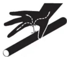
natural_image
Silhouette of a hand gripping a cylindrical object, no text or symbols presentDANGER
High Pressure Fluid Hazard:
Check all hydraulic lines and fittings before applying pressure. Relieve pressure before disconnecting hydraulic lines. Wear protective gloves and safety glasses or goggles when working with hydraulic systems. Fluid escaping from a very small hole can be almost invisible. Use paper or cardboard, NOT BODY PARTS, to check for leaks. Escaping fluid under pressure can have sufficient pressure to penetrate the skin causing serious injury. If hydraulic fluid is injected into the skin or eyes, seek immediate medical assistance from a physician familiar with this type of injury. Within a few hours gangrene can start to develop. DO NOT DELAY. Only trained personnel should work on system hydraulics.

natural_image
Three black silhouette icons representing different fire extinguishers or tools (no text or symbols)Lockout Valves
Refer to Figure 8
Before operating the lockout valves, always:
a. Apply the tractor parking brake.
b. Stop the tractor engine.
c. Take the key with you to prevent unauthorized starting.
There are two wing lockout valves(1) located at the rear of the hay rake. One on each of the wing lift cylinders.
When the two wing lockout valves are in the unlocked position, the wings will raise and lower using the tractor remote lever.
When the two wing lockout valves are in the locked position, the wings will not raise or lower.
If equipped with a kicker wheel(s), the kicker lockout valve is located at the rear of the hay rake between the wing lockout valves. When the kicker lockout valve is in the unlocked position, the kicker will raise and lower with the wings.
When the kicker lockout valve is in the locked position, the kicker wheel(s) will not raise or lower.
When roading or storing the hay rake, raise the wings and, if equipped, raise the kicker. Then put all lockout valves in the locked position.
Raising and Lowering the Wings Raising
- Make sure the wing lockout valves and, if equipped, the kicker lockout valve are in the unlocked position.
- Park the machine on a solid, level surface.
- Operate the tractor remote lever to raise the wings and, if equipped, the kicker.
- Apply the tractor parking brake. Stop the tractor engine and take the key with you to prevent unauthorized starting.
- Put the wing lockout valves and, if equipped, the kicker lockout valve in the locked position.
Lowering
- Make sure the wing lockout valves and, if equipped, the kicker lockout valve are in the unlocked position.
- Park the machine on a solid, level surface.
- Operate the tractor remote lever to lower the wings and, if equipped, the kicker.
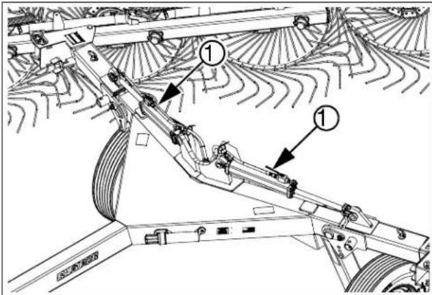
Figure 8 Wing Lockout Valves
38863
NOTICE
Raise the wing(s) at the edge of a field to extend the life of the rake and the rake wheels.
Raising the wing(s) is necessary for good windrow formation. Raise the wings high enough to clear the crop on the ground. Make the turn and then lower the wings.
NOTICE
Raising and lowering the wings will bleed the hydraulic system.
Roading the Hay Rake
WARNING
Do not transport going too fast for the terrain. Slow down if obstacles are present that the hay rake can hit and jerk the tractor around. Slow down if terrain is rough causing tractor to bounce. Either situation can cause operator to lose control and result in serious injury or death.
WARNING
Do not transport hay rake above 40 kph (25 mph). Doing so can result in loss of control resulting in equipment damage and serious injury or death.
Roading Checklist
☐ Plan the route so that no reverse movements will be necessary. Avoid steep hills. Keep Clearances in mind.
☐ Never exceed 8 kph (5 mph) in turns. The hay rake is top heavy and can tip.
☐ Hitch the hay rake to the tractor. Make sure the electrical and hydraulic connections are complete. See “Hitching and Unhitching the Rake” on page 11.
☐ If the wings are unfolded, fold them.
See “Raising and Lowering the Wings” on page 15
☐ Make sure the lockout valves for the wings are in the locked position. See "Lockout Valves" on page 15.
☐ If equipped with a kicker, make sure the kicker is raised and the kicker lockout valve is in the locked position. See “Lockout Valves” on page 15
☐ Make sure the SMV Safety sign is clean and visible. If needed, a SMV sign can be purchased from your nearest Kubota dealer.
☐ If equipped, always have lights on for highway operation.
□ Comply with all federal, state and local safety laws when traveling on public roads.
□ Travel with caution.
WARNING
When traveling on public roads, use accessory lights, SMV sign, clean reflectors, and other adequate devices to warn operators in other vehicles of your presence. Always comply with all federal, state, and local laws.
WARNING
Reduce tractor ground speed to 8 kph (5 mph) when turning. Turning too fast can cause the hay rake to tip causing serious injury or death.
Roading
- Do all of the items under Roading Checklist.
- Start tractor and select a safe ground travel speed when transporting from one area to another. Do not exceed 40 kph (25 mph) travel speed.
- When traveling on roadways, transport in such a way that faster moving vehicles can pass you safely.
- Reduce tractor ground speed to 8 kph (5 mph) when turning. Turning too fast can cause the hay rake to tip. Leave enough clearance so the hay rake does not contact obstacles such as buildings, trees, or fences.
- Shift tractor to a lower gear when traveling over rough or hilly terrain.
Raking with Both Wings
- Park the tractor and the hay rake on a solid level surface in the field to be raked.
- Apply the tractor parking brake. Stop the tractor engine and take the key with you to prevent unauthorized starting.
Refer to Figure 9
- Go the rear of the rake. Put the wing lockout valves(1) in the unlocked position.
- If the rakes is equipped with optional kicker wheel(s), there is a kicker lockout valve between the wing lockout valves. If the kicker is to be used, put the kicker lockout valve in the unlocked position. The kicker wheel(s) will raise and lower with the wings.
- Lower the wings, and if using, the kicker wheel(s).
- Apply the tractor parking brake. Stop the tractor engine and take the key with you to prevent unauthorized starting.
- Adjust the angle of the wings. See "Adjusting the Wing Angle" on page 23.
- If necessary, adjust the wing spread. See "Adjusting the Wing Spread" on page 24.
- Make sure the rake frame is level and all of the rake wheels touch the ground evenly. If the rake wheels do not touch the ground evenly, see "Leveling the Rake Wheels" on page 21.
Refer to Figure 10
- Operate the rake and make sure the rake wheels all contact the ground evenly.
a. If a rake wheel is higher or lower than the other rake wheels, see "Adjusting Individual Rake Wheel Down Pressure" on page 25.
b. On Models RA210CR and RA212CR, if an entire wing is too high or too low, see "Adjusting Wing Down Pressure" on page 26.
NOTICE
Raise the wing(s) at the edge of a field to extend the life of the rake and the rake wheels.
Raising the wing(s) is necessary for good windrow formation.
Raise the wings high enough to clear the crop on the ground. Make the turn and then lower the wings.
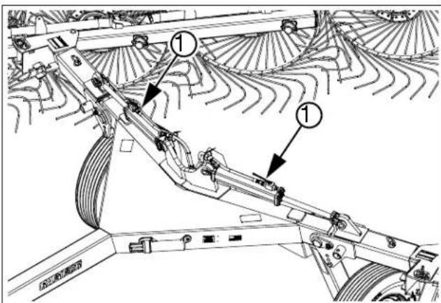
Figure 9 Wing Lockout Valves

natural_image
Symmetrical decorative pattern with repeating circular motifs and radiating lines (no text or symbols)Figure 10 Rake Wheels
Raking with One Wing
- Park the tractor and the hay rake on a solid level surface in the field to be raked.
- Raise the wings.
- Apply the tractor parking brake. Stop the tractor engine and take the key with you to prevent unauthorized starting.

When raking on slopes and when turning, reduce the speed. The rake can tip more easily with only one wing raised causing serious injury or death.
Refer to Figure 11
-
Go the rear of the rake.
Put the wing lockout valve for the wing being used in the unlocked position.
Put the wing lockout valve for the wing not being used in the locked position. -
If the rakes is equipped with optional kicker wheel(s), there is a kicker lockout valve between the wing lockout valves. If the kicker is to be used, put the kicker lockout valve in the unlocked position. The kicker wheel(s) will raise and lower with the wings.
-
Lower the wing, and if using, the kicker wheel(s).
-
Apply the tractor parking brake. Stop the tractor engine and take the key with you to prevent unauthorized starting.
-
Adjust the angle of the wing. See "Adjusting the Wing Angle" on page 23.
-
If necessary, adjust the wing spread. See "Adjusting the Wing Spread" on page 24.
-
Make sure the rake frame is level and all of the rake wheels touch the ground evenly. If the rake wheels do not touch the ground evenly, see "Leveling the Rake Wheels" on page 21.
Refer to Figure 12
- Operate the rake and make sure the rake wheels all contact the ground evenly.
a. If a rake wheel is higher or lower than the other rake wheels, see "Adjusting Individual Rake Wheel Down Pressure" on page 25.
b. On Models RA210CR and RA212CR, if an entire wing is too high or too low, see "Adjusting Wing Down Pressure" on page 26.
NOTICE
Raise the wing(s) at the edge of a field to extend the life of the rake and the rake wheels.
Raising the wing(s) is necessary for good windrow formation.
Raise the wings high enough to clear the crop on the ground. Make the turn and then lower the wings.
Raking with one wing is used to flip an existing windrow to speed drying time.

Figure 11 Wing Lockout Valves

natural_image
Symmetrical abstract pattern with repeating circular motifs and radiating lines (no text or symbols)Figure 12 Rake Wheels
Kicker Operation (Option)
A single or a dual kicker wheel kit can be added to the rear of the machine. The kicker wheel(s) move crop that would otherwise be left unturned at the bottom of the windrow.
Single Kicker Wheel (Option)
Refer to Figure 13
The optional single kicker wheel moves the crop to one side. The kit is mounted on the rear frame.
A kicker lockout valve is mounted in the center of the rear frame. When the kicker lockout valve is in the unlocked position, the kicker wheel will raise and lower with the wings.
When the kicker lockout valve is moved to the locked position, the kicker wheel will stay in that position.
If the kicker is not needed, raise the kicker and put the kicker lockout valve in the locked position

natural_image
Technical line drawing of a mechanical component with swirling internal flow pattern (no text or symbols)Figure 13 Single Kicker Wheel
Dual Kicker Wheels (Option)
Refer to Figure 14
The optional dual kicker wheels move the crop to both sides. The kit is mounted on the rear frame.
The optional dual kicker kit is mounted on the rear frame.
A kicker lockout valve is mounted in the center of the rear frame. When the kicker lockout valve is in the unlocked position, the kicker wheels will raise and lower with the wings.
When the kicker lockout valve is moved to the locked position, the kicker wheels will stay in that position.
If the kicker is not needed, raise the kicker and put the kicker lockout valve in the locked position
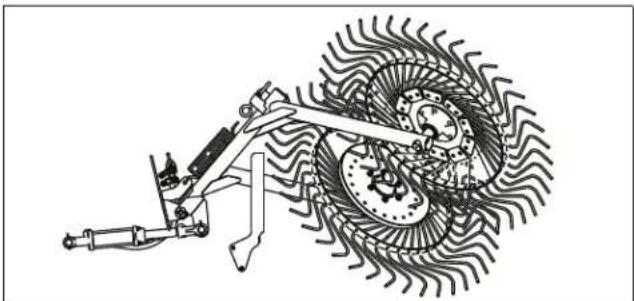
natural_image
Technical line drawing of a mechanical assembly with gear and shaft components (no text or symbols)Figure 14 Dual Kicker Wheel
Parking
- Raise the wings and, if equipped, the kicker wheel(s).
- Park the tractor and the rake on a solid level surface. If necessary, make sure there is enough space to lower the wings.
- Apply the tractor parking brake. Stop the tractor engine and take the key with you to prevent unauthorized starting.
- Go the rear of the rake. Put the wing lockout valves, and if equipped, the kicker lockout valve in the locked position.
Storage
Refer to Figure 15
It is recommended that the rake be stored inside and the wings be in the raised position.
1. If the wings are lowered, raise the wings. If equipped with a kicker, put the kicker lockout valve in the locked position.
2. Park the rake in the storage area.
3. Apply the tractor parking brake. Stop the tractor engine and take the key with you to prevent unauthorized starting.
4. Put the wing lockout valves in the locked position. If equipped with a kicker, put the kicker lockout valve in the locked position.
5. Lubricate the rake as indicated under "Lubrication" on page 33.
6. Check all tires for proper inflation. See "Tire and Wheel Information Chart" on page 37.
7. Check all bolts, pins, and fasteners. Torque as shown in "Torque Values Chart" on page 37.
8. Check for worn or damaged parts. Repair or replace parts before going to the field.
9. Check hydraulic hoses, fittings, and cylinders for leaks. Repair or replace before going to the field.
10. Clean off all mud, dirt, excess oil and grease.
11. Inspect for worn or damaged parts. Make repairs and service during off season.
12. Apply grease to the rods of the hydraulic cylinders to prevent rust.
13. Use spray paint to cover scratches, chips, and worn areas to protect the metal.
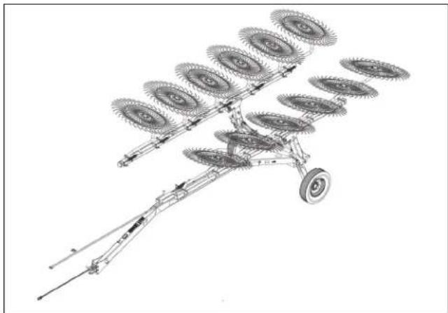
natural_image
Technical line drawing of a mechanical agricultural machine with multiple blades and wheels (no text or symbols)Figure 15 Rake Ready for Parking
Adjustments and Installations
Leveling the Rake Wheels
- Lower the wings.
- Apply the tractor parking brake. Stop the tractor engine and take the key with you to prevent unauthorized starting.
- Make sure all of the rake wheels contact the ground evenly.
a. If the rake wheels are lower in the front, put the hitch clevis in the next lower position to raise the front of the wings.
b. If the rake wheels are higher in the front, put the hitch clevis in the next higher position to lower the front of the wings.
"Initial Hitch Clevis Height Adjustment" on page 11 to adjust the alignment.
Adjusting Windrow and Raking Widths
Refer to Figure 16
See "Windrow Widths and Raking Widths Chart" on page 22. Find the desired windrow width and raking width.
The values in the chart are approximate values. Actual results will vary based on field conditions, crop conditions, and ground speed. Use these values as a starting point and adjust as needed.
Wing Angle Setting
Refer to the chart and determine the wing angle setting (1). To adjust the wing angle, see "Adjusting the Wing Angle" on page 23.
Wing Spread Setting
On models RA210CR and RA212CR the spread between the wings can be adjusted (2).
Refer to the chart and determine the wing angle(1) and spread setting(1). To adjust the wing spread, see "Adjusting the Wing Spread" on page 24.
If crop is catching between the rake wheels and the transport tires, extend the wing spread to create more room.

Figure 16
Wing Adjustments
68012
Windrow Widths and Raking Widths Chart RA108CR
If the rake is equipped with a wing extension kit, use the chart for the RA110CR.
| Pin Position 1 2 3 | 4 5 6 | |||||
| Windrow width 86 cm | (2' 10") 107 cm (3' 6") | 124 cm (4' 1") | 145 cm (4' 9") | 165 cm (5' 5") | 198 cm (6' 6") | |
| Raking width | 508 cm (16' 8") | 502 cm (16' 6") | 493 cm (16' 2") | 493 cm (16' 2") | 488 cm (16' 0") | 480 cm (15' 9") |
RA110CR
| Pin Position 1 2 3 4 5 6 | ||||||
| Windrow width | 86 cm (2' 10") | 107 cm (3' 6") | 124 cm (4' 1") | 145 cm (4' 9") | 165 cm (5' 5") | 198 cm (6' 6") |
| Raking width | 620 cm (20' 4") | 610 cm (20' 0") | 566 cm (19' 7") | 544 cm (19' 2") | 571 cm (18' 9") | 556 cm (18' 3") |
RA210CR
If the rake is equipped with a wing extension kit, use the chart for the RA212CR.
| Pin Position | 1 | 2 | 3 | 4 | 5 | 6 | |
| A | Windrow width | 91 cm (3' 0") | 107cm (3' 6") | 125 cm (4' 1") | 142 cm (4' 8") | 160 cm (5' 3") | 178 cm (5' 10") |
| Raking width | 594 cm (19' 5") | 587 cm (19' 3") | 579 cm (19' 0") | 568 cm (18' 8") | 589 cm(18' 4") | 589 cm (18' 0") | |
| B | Windrow width | 26 cm (3' 7") | 124 cm (4' 1") | 142 cm (4' 8") | 157 cm (5' 2") | 173 cm (5' 8") | 193 cm (6' 4") |
| Raking width | 610 cm (20' 0") | 587 cm (19' 9") | 494 cm (19' 6") | 584 cm (19' 2") | 577 cm (18' 11") | 566 cm (18' 7") | |
| C | Windrow width | 124 cm (4' 1") | 140 cm (4' 7") | 157 cm (5' 2") | 173 cm (5' 8") | 191 cm (6' 3") | 208 cm (6' 10") |
| Raking width | 625 cm (20' 6") | 617 cm (20' 3") | 610 cm (20' 0") | 599 cm (19' 8") | 594 cm (19' 5") | 581 cm (19' 1") | |
| D | Windrow width | 140 cm (4' 7") | 155 cm (5' 1") | 173 cm (5' 8") | 190 cm (6' 3') | 208 cm (6' 10") | 226 cm (7' 5") |
| Raking width | 640 cm (21' 0") | 632 cm (20' 9") | 625 cm (20' 6") | 617 cm (20' 3") | 607 cm (19' 11") | 597 cm (19' 7") | |
RA212CR
| Pin Position | 1 | 2 | 3 | 4 | 5 | 6 | |
| A | Windrow width | 91 cm (3' 0") | 107 cm (3' 6") | 125 cm (4' 1") | 142 cm (4' 8") | 160 cm (5' 3") | 178 cm (5' 10") |
| Raking width | 713 cm (23' 5") | 699 cm (22' 11") | 686 cm (22' 6") | 671 cm (22' 0") | 655 cm (21' 6") | 640 cm (21' 0") | |
| B | Windrow width | 26 cm (3' 7") | 124 cm (4' 1") | 142 cm (4' 8") | 157 cm (5' 2") | 173 cm (5' 8") | 193 cm (6' 4") |
| Raking width | 729 cm (23' 11") | 719 cm (23' 6") | 710 cm (23' 0") | 686 cm (22' 6") | 671 cm (22' 0") | 655 cm (21' 5") | |
| C | Windrow width | 124 cm (4' 1") | 140 cm (4' 7") | 157 cm (5' 2") | 173 cm (5' 8") | 191 cm (6' 3") | 208 cm (6' 10") |
| Raking width | 747 cm (24' 5") | 732 cm (24' 0") | 719 cm (23' 6") | 704 cm (23' 1") | 693 cm (22' 7") | 671 cm (22' 0") | |
| D | Windrow width | 140 cm (4' 7") | 155 cm (5' 1") | 173 cm (5' 8") | 190 cm (6' 3') | 208 cm (6' 10") | 226 cm (7' 5") |
| Raking width | 762 cm (25' 0") | 750 cm (24' 6") | 731 cm (24' 0") | 719 cm (23' 7") | 704 cm (23' 1") | 686 cm (22' 6") | |
Adjusting the Wing Angle
Refer to Figure 17
NOTICE
For maximum rake wheel life, operate rake so that the front rake wheels are as close together as possible.
- Determine the correct hole (1 thru 6) for the desired width. See "Windrow Widths and Raking Widths Chart" on page 22.
- Park the rake on a solid level surface.
- Lower the wings.
- Apply the tractor parking brake. Stop the tractor engine and take the key with you to prevent unauthorized starting.
- Remove the wing hitch pin (1) from the wing arm.
- Swing the wing to align the holes.
- Install the wing hitch pin.
- Repeat the procedure for the other wing.

Figure 17 Adjusting the Wing Angle
Adjusting the Wing Spread
RA210CR and RA212CR
Refer to Figure 18
NOTICE
Do not adjust wing spread with wings in the raised position. Damage to parking jack can occur.
-
Determine the which hole (A thru D) is to be aligned with the hole (1) in the inner wing strut. See "Adjusting Windrow and Raking Widths" on page 21.
-
Park the rake on a solid level surface.
-
Lower the wings.
-
Apply the tractor parking brake. Stop the tractor engine and take the key with you to prevent unauthorized starting.
-
Remove the parking jack from the tongue.
-
Attach the foot of the parking jack to the bracket (2) on the outer wing strut.
-
Adjust the parking jack to align the mounting tube of the parking jack with the mounting tube (3) on the inner wing strut.
-
Install the parking jack in the mounting tube and install the detent pin.
-
Remove the spread hitch pin (4) from the inner wing strut.
-
Operate the parking jack to align the desired holes.
-
Install the spread hitch pin.
-
Remove the parking jack.
-
Repeat the procedure for the other wing.
-
Install the parking jack on the top of the tongue.
If crop is catching between the rake wheels and the transport tires, extend the wing spread to create more room.
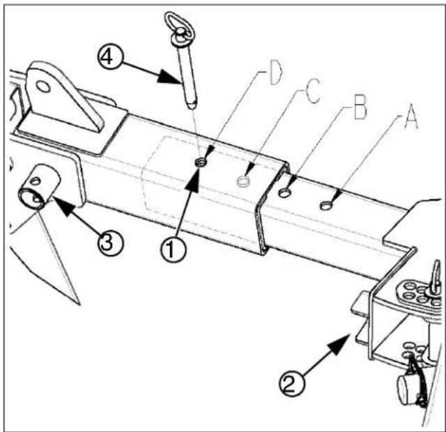
Figure 18 Adjusting Wing Spread
Adjusting Individual Rake Wheel Down Pressure
The stop bumpers (1) on the wheel arms are for shipping purposes. The rake can be operated with the stop bumpers installed. Stop bumpers are not required for proper rake operation.
Refer to Figure 19
- Park the rake on a solid level surface.
- Lower the wings.
- Apply the tractor parking brake. Stop the tractor engine and take the key with you to prevent unauthorized starting.
- Locate the eyebolt (2) for the spring (3).
Refer to Figure 20
- Measure the distance (A) from the end of the eyebolt to the outer face of the inner jam nut. The initial distance must be 2.5 in (63.5 mm).
-
Operate the rake to check the down pressure.
-
Apply the tractor parking brake. Stop the tractor engine and take the key with you to prevent unauthorized starting.
-
To adjust the down pressure:
a. Increase distance (A) to increase the flotation pressure.
b. Decrease distance (A) to decrease the flotation pressure.
c. Tighten the nuts on the eyebolt without changing the adjustment.

Figure 19 Down Pressure Spring and Eye Bolt

Figure 20 Down Pressure Adjustment
Adjusting Wing Down Pressure
RA210CR and RA212CR
Refer to Figure 21
- Park the rake on a solid level surface.
- Raise the wings.
- Apply the tractor parking brake. Stop the tractor engine and take the key with you to prevent unauthorized starting.
- Put all of the lockout valves in the locked position. "Lockout Valves" on page 15.
- Remove the hex flanged nut (1) and flat washer (2) from the bolt (3) in the ears (4) on the inner wing strut (5).
- Move the cap screw to one of the three holes.
a. Using the hole farthest from the pivot will stop the wings in a lower position. This position will increase the down pressure on the rake wheels.
b. Using the hole closest to the pivot will stop the wings in a higher position. This position will decrease the down pressure on the rake wheels.
-
Install the flat washer and the flanged lock nut on the bolt. Tighten the flanged lock nut to 304 N m (265 lb-ft).
-
Repeat the procedure for the other wing.
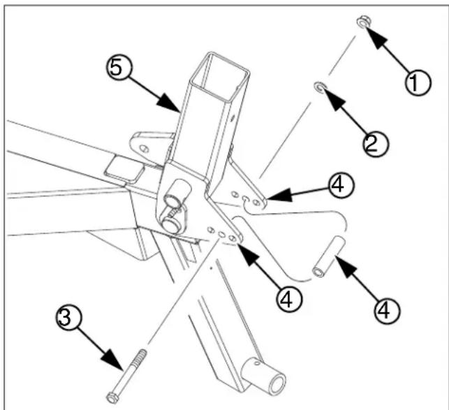
Figure 21
38952
Down Pressure Adjustment
Troubleshooting
| Problem Cause | Solution | |
| Rake wheels digging too much into the ground | Not enough flotation on the rake wheel arms. | Adjust the eyebolt on the rake wheel arms to extend the flotation spring |
| Rake wing traveling too low | If operating a RA210CR or RA212CR rake, adjust the wing stop bolts to a higher position | |
| Rake wings adjusted too wide at front | Adjust the rake wing angle to reduce the width at the front | |
| Rake wheels bouncing too much or not reaching the ground | Too much flotation on the rake wheel arms. | Adjust the eyebolt on the rake wheel arms to reduce the flotation spring length |
| Rake wing stopping too high | If operating a RA210CR or RA212CR rake, adjust the wing stop bolts to a lower position | |
| Crop bunching between rake wheels and tire | Not enough clearance between rake wheels and transport tires | If operating a RA210CR or RA212CR rake, extend the wing arms to create more clearance |
| Raking too much material Reduce the raking width | ||
| Crop is dragging instead of moving to middle | Rake wings adjusted too wide at front | Adjust the rake wing angle to reduce the width at the front |
| Rake wings not raising evenly | Wing cylinders getting out of synchronization | Continue holding the tractor hydraulic remote valve for 1-2 seconds after cylinders are fully extended or retracted |
| One cylinder lockout valve partially closed | Make sure that both cylinder lockout valves are completely opened | |
| Contamination plugging one cylinder orifice | Check orifice at base of slower fold cylinder for contamination | |
| Left-hand and right-hand wings not adjusted equally | It is acceptable to not have the wings adjusted equally, however, uneven folding will result | |
| Rake wheel tines breaking prematurely | Not enough flotation on the rake wheel arms | Adjust the eyebolt on the rake wheel arms to extend the flotation spring |
| Rake wings operating at too wide of an angle | Adjust the rake wing angle to reduce the width at the front | |
| Making sharp turns with wings lowered | Raise wings to lift rake wheel off ground before making sharp turns | |
| Rake wheels not turning | Rake wheel hub not turning freely Check | the hub bearings and seal. Repair as necessary. |
| Material wrapped around spindle and dragging against rake wheel | Remove wrapped material from rake | |
| Wing angle too wide | Some conditions require a narrower wing angle. Adjust wing angle as necessary. | |
Maintenance and Lubrication
Maintenance
Proper servicing and maintenance is the key to long implement life. With careful and systematic inspection, you can avoid costly maintenance, downtime, and repair.
Always turn off and remove the tractor key before making any adjustments or performing any maintenance.

WARNING
Crushing Hazard:
Always have transport locks in place and frame sufficiently blocked up when working on implement. You may be severely injured or killed by being crushed under the falling implement.

DANGER
High Pressure Fluid Hazard:
Check all hydraulic lines and fittings before applying pressure. Relieve pressure before disconnecting hydraulic lines. Wear protective gloves and safety glasses or goggles when working with hydraulic systems. Fluid escaping from a very small hole can be almost invisible. Use paper or cardboard, NOT BODY PARTS, to check for leaks. Escaping fluid under pressure can have sufficient pressure to penetrate the skin causing serious injury. If hydraulic fluid is injected into the skin or eyes, seek immediate medical assistance from a physician familiar with this type of injury. Within a few hours gangrene can start to develop. DO NOT DELAY. Only trained personnel should work on system hydraulics.
- After using your hay rake for several hours, check all bolts to be sure they are tight.
- Maintain proper air pressure in the tires.
- Clean hay rake on a regular basis. Regular and thorough cleaning will lengthen equipment life and reduce maintenance and repair.
- Lubricate areas listed under "Lubrication" on page 33.
- Replace any worn, damaged, or illegible safety labels by obtaining new labels from your Kubota dealer.
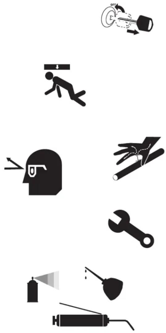
natural_image
Collection of black-and-white icons representing various workplace and safety symbols (no text or labels)Bleeding the Hydraulic System
DANGER
High Pressure Fluid Hazard:
Check all hydraulic lines and fittings before applying pressure. Relieve pressure before disconnecting hydraulic lines. Wear protective gloves and safety glasses or goggles when working with hydraulic systems. Fluid escaping from a very small hole can be almost invisible. Use paper or cardboard, NOT BODY PARTS, to check for leaks. Escaping fluid under pressure can have sufficient pressure to penetrate the skin causing serious injury. If hydraulic fluid is injected into the skin or eyes, seek immediate medical assistance from a physician familiar with this type of injury. Within a few hours gangrene can start to develop. DO NOT DELAY. Only trained personnel should work on system hydraulics.
WARNING
System Contamination Risk:
Always use liquid pipe sealant when adding or replacing NPT (National Pipe Thread, tapered thread) pipe-thread fittings. To avoid cracking hydraulic fittings from over tightening, and to keep tape fragments from clogging filters, do not use plastic sealant tape.
- Put both wing lockout valves in the unlocked position. If equipped with a kicker wheel(s), put the kicker wheel lockout valve in the unlocked position.
-
Park the machine on a solid, level surface. Make sure there is room to safely raise and lower the wings.
-
Raise and lower the wings several times.
If equipped with a kicker wheel(s), the kicker wheel(s) will raise and lower with the wings.
- When the movements are smooth and even, the air has been removed from the hydraulic system.

JIC Torque Chart
| Size Foot- | Pounds N-m | |
| ^7/_16 -20 | 11-12 15-16 | |
| ^1/_2 -20 | 15-16 20-22 | |
| ^9/_16 -18 | 18-20 24-28 | |
| ^3/_4 -16 | 38-42 52-58 | |
| ^7/_8 -14 | 57-62 77-85 | |
| ^11/_16 -12 | 79-87 108-119 |
NOTICE
Over-Torque Leak Risk:
JIC (Joint Industry Conference 37° Flare) fittings do not require high torque. Excess torque causes leaks. JIC and ORB (O-Ring Boss) fittings do not require sealant.
NOTICE
Bleed only at JIC and NPT fittings.
Never try to bleed a QD (Quick Disconnect) fitting.
Avoid bleeding at ORB fittings. The O-ring is likely to be torn if any pressure remains in the circuit.
Rake Wheel Removal and Installation
Refer to Figure 22
Removal
- Park the rake on a solid level surface.
- Lower the wings.
- Apply the tractor parking brake. Stop the tractor engine and take the key with you to prevent unauthorized starting.
- Remove six nuts (1) from the rake wheel (2).
- Remove the rake wheel.
Installation
- Install the rake wheel on the hub (3). The side of the rake wheel with the series of small plates (4) must be toward the hub.
- Install the six flange lock nuts that fasten the rake wheel to the hub.
- Tighten the flange lock nuts to 35 N m (26 lb ft).

Figure 22 Rake Wheel Installation
Rake Wheel Hub Removal and Installation
Refer to Figure 23
Removal
- Park the rake on a solid level surface.
- Lower the wings.
- Apply the tractor parking brake. Stop the tractor engine and take the key with you to prevent unauthorized starting.
- Remove six nuts from the rake wheel. See "Rake Wheel Removal and Installation" on page 30.
- Remove the rake wheel.
- Remove the dust cap from the hub (1).
- Remove the cotter pin (2) from the castellated nut (3).
- Remove the castellated nut from the spindle (4).
- Remove the flat washer (5).
- Remove the hub (6) assembly.

Figure 23 Rake Wheel Hub
38937
Disassembly and Assembly
- Remove the outer bearing race and cone (7) from the hub (6).
- Pry the seal (8) from the rear of the hub. Be careful not to damage the sealing surface of the hub. Discard the seal.
- Remove the inner bearing race and cone (9) from the hub.
- Inspect both bearings and replace as necessary.
- Inspect the races in the hub for damage and replace if necessary
- Thoroughly clean the inside of the hub.
- Pack the inner and the outer bearing cones with grease.
- Apply grease to the both bearing races, the inside of the hub, and the lip of the seal.
- Install the inner bearing race and cone.
- Press the new seal into the hub using equal pressure all the way around the seal.
- Apply grease to the spindle.
Installation
- Install the hub on the spindle.
- Install the outer bearing race and cone.
- Install the flat washer.
- Install the castellated nut. Tighten the castellated nut until snug. Loosen the just enough to align a slot in the castellated nut with the hole in the spindle.
- Install the cotter pin.
- Install the dust cap.
Transport Wheel Removal and Installation
Removal
- Park the rake on a solid level surface.
- Apply the tractor parking brake. Stop the tractor engine and take the key with you to prevent unauthorized starting.
- If the wings are raised, put the wing lockout valves in the locked position.
- Loosen, but do not remove, the lug nuts for the transport wheel.
- Use lifting equipment to raise the frame just enough to raise the transport wheel off the ground.
- Remove the transport wheel.
Installation
- Install the transport wheel on the wheel studs.
- Install the lug nuts on the wheel studs. Tighten the lug nut until the lug nuts are centered in the holes in the rim.
- Lower the rake and remove the lifting equipment.
- Tighten the lug nuts in an alternating pattern. "Tire and Wheel Information Chart" on page 37 for the correct torque.
Lubrication

Wing Pivots
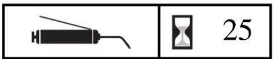
One grease fitting on each wing pivot; 2 total
Grease fittings are only accessible when wings are raised.
Type of Lubrication: Grease
Quantity: Five pumps or until Grease emerges

natural_image
Technical line drawing of a mechanical assembly with no visible text or symbolsOptions
■ LED Safety Light Kit
This option provides LED lighting for roading the rake. The kit consist of a harness, a lighting module, and four LED lamps.
| Option Package Part Number | |
| LED Safety Light Kit 512-014A82 |
■ Single Kicker Kit
This option provides a single kicker wheel that is mounted on the rear of the rake. The kicker wheel moves crop at the center of the rake that might otherwise might not be moved.
| Option Package Part Number | |
| Single Kicker Wheel Kit 512-040A82 |
■ Dual Kicker Kit
This option provides two smaller kicker wheels that are mounted on the rear of the rake. The kicker wheels move crop at the center of the rake that might otherwise might not be moved.
| Option Package Part Number | |
| Dual Kicker Wheel Kit 512-041A82 |

natural_image
Technical line drawing of a mechanical component with swirling internal flow pattern (no text or symbols)
natural_image
Mechanical assembly diagram showing gear and shaft components (no text or labels)■ 8 Wheel Wind Screen Kit
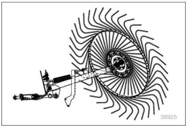
The eight wind screens are used to reduce the effect of wind on the crop during raking. The kit includes cable ties for attaching the wind screens to the rake wheels.
| Option Package Part Number | |
| Eight Wheel Wing Screen Kit 512-048A |
■ 10 Wheel Wind Screen Kit
The 10 wind screens are used to reduce the effect of wind on the crop during raking. The kit includes cable ties for attaching the wind screens to the rake wheels.
| Option Package Part Number | |
| Ten Wheel Wing Screen Kit 512-049A |
■ 12 Wheel Wind Screen Kit
The 12 wind screens are used to reduce the effect of wind on the crop during raking. The kit includes cable ties for attaching the wind screens to the rake wheels.
| Option Package Part Number | |
| Twelve Wheel Wing Screen Kit 512-050A |

natural_image
Simple line drawing of two concentric ovals with a small circle inside, no text or symbols present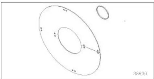
natural_image
Simple line drawing of two concentric ovals with small dots, no text or symbols present
natural_image
Simple line drawing of two concentric ovals with small dots, no text or symbols presentAppendix - Reference Information
Specifications
Model RA108CR RA110CR RA210CR RA212CR
| Transport Length | A | 645 cm (21'-2") | 645 cm (21'-2)" | 757 cm (24'-10") | 757 cm (24'-10") |
| Working Length (Max.) B 655 cm (21'-6") 772 cm (25'4") | |||||
| Transport Width | C | 284 cm (9'-4") | 290 cm (9'-6") | 279 cm (9'-2") | 282 cm (9'-3") |
| Transport Height, Min. | D | 244 cm (8') | 244 cm (8') | 254 cm (8'-4") | 254 cm (8'-4") |
| Transport Height, Max. | E | 257 cm (8'-5") | 267 cm (8'-9") | 292 cm (9'-7") | 302 cm (9'-11") |
| Min. Working Width | F | 478 cm (15'-8") | 589 cm (18'-4") | 549 cm (18') | 640 cm (21') |
| Max. Working Width | G | 508 cm (16'-8") | 620 cm (20'-4") | 640 cm (21') | 762 cm (25') |
| Min. Windrow | 86 cm (34 in) | 86 cm (34 in) | 91 cm (36 in) | 91 cm (36 in) | |
| Max. Windrow | 183 cm (72 in) | 183 cm (72 in) | 226 cm (89 in) | 226 cm (89 in) | |
| Working Height | 140 cm (55 in) | ||||
| Typical Weight w/o Options | 662 kg (1460 lb) | 734 kg (1640 lb) | 812 kg (1790 lb) | 893 kg (1970 lb) | |
| Wing Spread | NA | One hole changes windrow and working width 15 to 18 cm (6 to 7 in) | |||
| Hydraulic Circuits | Closed-center or Open-center, one remote | ||||
| Hydraulic Power Required | 12410 kPa, 38 L/min (1800 psi, 10 gpm) | ||||
| Minimum Tractor hp | 30 hp | 40 hp | 40hp | 50 hp | |
D, E
A, B
C
F, G
38963
38962
38967
Torque Values Chart
| Bolt Sizein-tpia | Bolt Head Identification | |||||
 Grade 2 Grade 2 |  Grade 5 Grade 5 |  Grade 8 Grade 8 | ||||
| N-mb | ft-lbd | N-m | N-ftl-lb | ft-lb | ||
| ^1/_4-20 | 7.4 11 | 16.6 | 8 | 12 | ||
| ^1/_4-28 | 8.5 13 | 18 6 | 10 | 14 | ||
| ^5/_16-18 | 15 24 | 3311 17 | 25 | |||
| ^5/_16-24 | 17 26 | 371319 | 27 | |||
| ^3/_8-16 | 27 42 | 5920 | 31 | 44 | ||
| ^3/_8-24 | 31 | 22 | 47 | 35 | 67 | 49 |
| ^7/_16-14 | 4367 | 9532 | 49 | 70 | ||
| ^7/_16-20 | 49 75 | 36 | 105 | 55 | 78 | |
| ^1/_2-13 | 66 | 49 76 | 105 | 105 | 145 | |
| ^1/_2-20 | 75 | 55 | 115 | 85 | 165 | 120 |
| ^9/_16-12 | 95 | 70 | 150 | 110 | 210 | 155 |
| ^9/_16-18 | 105 | 79 | 165 | 120 | 235 | 170 |
| ^5/_8-11 | 130 | 97 | 205 | 150 | 285 | 210 |
| ^5/_8-18 | 150 | 110 | 230 | 170 | 325 | 240 |
| ^3/_4-10 | 235 | 170 | 360 | 265 | 510 | 375 |
| ^3/_4-16 | 260 | 190 | 405 | 295 | 570 | 420 |
| ^7/_8-9 | 225 | 165 | 585 | 430 | 820 | 605 |
| ^7/_8-14 | 250 | 185 | 640 | 475 | 905 | 670 |
| 1-8 | 340 | 250 | 875 | 645 | 1230 | 910 |
| 1-12 | 370 | 275 | 955 | 705 | 1350 | 995 |
| 1^1/_8-7 | 480 | 355 | 1080 | 795 | 1750 | 1290 |
| 1^1/_8-12 | 540 | 395 | 1210 | 890 | 1960 | 1440 |
| 1^1/_4-7 | 680 | 500 | 1520 | 1120 | 2460 | 1820 |
| 1^1/_4-12 | 750 | 555 | 1680 | 1240 | 2730 | 2010 |
| 1^3/_8-6 | 890 | 655 | 1990 | 1470 | 3230 | 2380 |
| 1^3/_8-12 | 1010 | 745 | 2270 | 1670 | 3680 | 2710 |
| 1^1/_2-6 | 1180 | 870 | 2640 | 1950 | 4290 | 3160 |
| 1^1/_2-12 | 1330 | 980 | 2970 | 2190 | 4820 | 3560 |
| Bolt Sizemm x pitch ^c | Bolt Head Identification | |||||
 Class 5.8N-m N-ft-N-m Class 5.8N-m N-ft-N-m |  Class 8.8ft-lb Class 8.8ft-lb |  Class 10.9ft-lb Class 10.9ft-lb | ||||
| M 5 X 0.8 | 3 | 5 | 94 | 7 | ||
| M 6 X 1 | 7 | 5 | 1 | 8 | 1 | 11 |
| 12 M9X 1.25 | 17 26 | 36 | ||||
| 1321M9X 1 | 1828 | 39 | ||||
| M10 X 1.5 | 3352 | 7224 | 39 | 53 | ||
| M10 X 0.75 | 39 | 29 | 61 | 45 | 85 | 62 |
| M12 X 1.75 | 5891 | 42 | 125 | 67 | 93 | |
| M12 X 1.5 | 60 95 | 44 | 130 | 70 | 97 | |
| M12 X 1 66 | 7790 | 10505 | 145 | |||
| M14 X 2 | 92 | 68 | 145 | 105 | 200 | 150 |
| M14 X 1.5 | 99 | 73 | 155 | 115 | 215 | 160 |
| M16 X 2 | 145 | 105 | 225 | 165 | 315 | 230 |
| M16 X 1.5 | 155 | 115 | 240 | 180 | 335 | 245 |
| M18 X 2.5 | 195 | 145 | 310 | 230 | 405 | 300 |
| M18 X 1.5 | 220 | 165 | 350 | 260 | 485 | 355 |
| M20 X 2.5 | 280 | 205 | 440 | 325 | 610 | 450 |
| M20 X 1.5 | 310 | 230 | 650 | 480 | 900 | 665 |
| M24 X 3 | 480 | 355 | 760 | 560 | 1050 | 780 |
| M24 X 2 | 525 | 390 | 830 | 610 | 1150 | 845 |
| M30 X 3.5 | 960 | 705 | 1510 | 1120 | 2100 | 1550 |
| M30 X 2 | 1060 | 785 | 1680 | 1240 | 2320 | 1710 |
| M36 X 3.5 | 1730 | 1270 | 2650 | 1950 | 3660 | 2700 |
| M36 X 2 | 1880 | 1380 | 2960 | 2190 | 4100 | 3220 |
Torque tolerance + 0%, -15% of torquing values. Unless otherwise specified use torque values listed above.
25199
Tire and Wheel Information
| Tire and Wheel Information Chart Tire Wa | ||
| Tire Size Inflation | Wheel Hardware Torque | |
| ST205/75R15(Load 1820) | 60 psi(414 kPa) | 85 lb-ft(115 N m) |
All tires are warranted by the original manufacturer of the tire. Tire warranty information is found in the brochures included with your Operator's and Parts Manuals or online at the tire manufacturer's web site.
Hydraulic Connectors and Torque
Refer to Figure 24 (a hypothetical fitting)
Leave any protective caps in place until immediately prior to making a connection.
① NPT - National Pipe Thread
Note tapered threads, no cone/flare, and no O-ring.
Apply liquid pipe sealant for hydraulic applications.
Do not use tape sealant, which can clog a filter and/or plug an orifice.
② JIC - Joint Industry Conference (SAE J514)
Note straight threads (4) and the 37° cone (5) on "M" fittings (or 37° flare on "F" fittings).
Use no sealants (tape or liquid) on JIC fittings.
ORB - O-Ring Boss (SAE J514)
③ Note straight threads (6) and elastomer O-Ring (7).
Prior to installation, to prevent abrasion during tightening, lubricate O-Ring with clean hydraulic fluid.
Use no sealants (tape or liquid) on ORB fittings.
ORB fittings that need orientation, such as the ell depicted also have a washer (8) and jam nut (9) ("adjustable thread port stud"). Back jam nut away from washer. Thread fitting into receptacle until O-Ring contacts seat. Unscrew fitting to desired orientation. Tighten jam nut to torque specification.

Figure 24 Hydraulic Connector ID
| Fittings Torque Values | ||
| Fitting Call Size N-m | Ft-Lbs- | |
| ^1/_4 NPT | 1.5-3.0 turns past finger tight | |
| ^5/_16 JIC | 24 to 27 18 to 20 | |
| ^5/_16 ORB w/jam nut | 16 to 22 12 to 16 | |
| ^5/_16 ORB straight | 24 to 32 18 to 24 | |
| ^3/_4 JIC | 37 to 53 27 to 39 | |
| ^3/_4 ORB w/jam nut | 27-41 20 to 30 | |
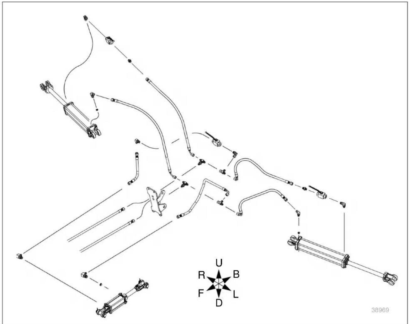
Hydraulic Diagrams Without Optional Kicker
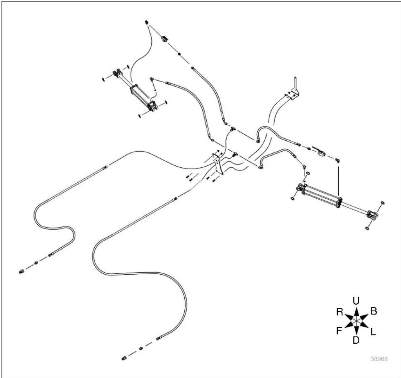
With Optional Kicker
Wiring Diagram

Table of Contents Index
Index
A
adjusting individual rake wheel down
pressure 25
adjusting the wing angle ....23
adjusting windrow and raking widths ..21
amber reflector 7
appendix - reference information .....36
B
bleeding hydraulics .....29
C
CAUTION, defined 2
checklists
pre-start 14
transport 16
children 4
clothing 2
covered models ....1
customer service ....1
D
DANGER, defined 2
decal replacement ....6
decals
hazard excessive speed ....7
warning general instruction ....8 pinch point hazard ....8 pinching or shearing hazard ...9 tire pressure and torque ....9 warning (in Spanish) ....8
decal, safety 6
drugs or alcohol 5
dual kicker kit....34
dual kicker wheels 19
E
eight wheel wind screen kit ....35
English 8
F
fire 2
fumes....5
funnel material ....1
H
headphones 2
hearing 2
high pressure fluids ....3
hitch clevis 11
hydraulic connectors ....38
hydraulic diagram 38
hydraulic diagrams ......39
hydraulic safety ....3
I
inflation 37
J
JIC....38
Joint Industry Conference 38
J514 38
K
kicker kit, dual 34
kicker kit, single.... 34
kicker lockout valve 15
kicker operation.... 19
kicker wheels, dual.... 19
kicker wheel, single 19
L
leaks.... 3
LED safety light kit 34
leveling the rake wheels.... 21
lights.... 3
lockout valves 15
lockout valves, wing 15
lockout valve, kicker 15
lubrication.... 33
M
maintenance 28
maintenance safety 5
medical assistance.... 3
model number 1
N
National Pipe Thread 38
NPT 38
O
options 34
ORB 38
O-Ring Boss.... 38
P
paint 20
parking 20
plastic sealant tape 29
protective equipment.... 2
R
raising wing(s) at the edges of a field 19
raking with both wings 17
raking with one wing 18
red reflectors 6
reference information 36
reflectors
daytime 7
red....6
SMV 6
reflectors, safety.... 6
repair parts 1
Riders.... 4
riders 4
S
SAE J514 38
safety chain ....3
safety decal ....6
safety symbol....2
serial number ....1
setup 10
shutdown 4
single kicker kit ....34
single kicker wheel ....19
Spanish....8
specifications 36
storage....4,20
symbol, safety....2
T
tables
document family ....1
fittings torque 38
models covered ....1
torque values ....37
troubleshooting general ....27
tape, pipe 29
ten wheel wind screen kit ....35
Tipping 5
tipping 4,16,18
tire and wheel information ....37
tire inflation 37
tires 3
transport speed....4
troubleshooting 27
twelve wheel wind screen kit ....35
U
unauthorized starting 5,13
W
warning
high pressure fluid hazard .....7
WARNING, defined 2
warranty 37
welding 5
wind screen kit, eight wheel....35
wind screen kit, 10 wheel .....35
wind screen kit, 12 wheel .....35
windrow widths and raking widths chart . 22
wing extension kit ....36
wiring diagram 41
Numerics
25 mph....4,16
40 kph 4,16
5 mph.... 4, 5, 16
8 kph....4,5,16
818-055C, reflector 6
818-337C, decal 7
818-491C, decal 9
818-557C, decal 8
818-589C, decal 8
818-590C, decal 7
838-267C, reflector 7
848-210C, decal 9
858-840C, decal 8
KUBOTA Corporation is...
Since its inception in 1890, KUBOTA Corporation has grown to rank as one of the major firms in Japan. To achieve this status, the company has through the years diversified the range of its products and services to a remarkable extent. 30 plants and 35000 employees produce over 1000 different items, large and small.
All of these products services, however, are unified by one central commitment: KUBOTA makes products that are basic national necessities. Products which are indispensable. Products which are intended to help individuals and nations fulfill the potential inherent in their environment. KUBOTA is the world's basic necessities giant.
These necessities includes water supply, food from the soil and sea, industrial development, architecture and construction, and transportation. Thousands of people depend on KUBOTA's know-how, technology, experience, and customer service. Our promise is that you, too, can depend on KUBOTA.
Kubota®
KUBOTA TRACTOR CORPORATION
U.S.A. Corporate : 3401 Del Amo Blvd., Torrance, CA 90503
Telephone : (310) 370-3370
Western Division : 1175 S. Guild Avc., Lodi, CA 95240
Telephone : (209) 334-9910
Central Division: 14855 FAA Blvd., Fort Worth, TX 76155
Telephone : (817) 571-0900
Northern Division : 6300 at One Kubota Way, Groveport, OH 43125
Telephone : (614) 835-1100
Southeast Division : 1025 Northbrook Parkway, Suwanee, GA 30024
Telephone : (770) 995-8855
- Kubota®
- ■ Machine Identification
- Dealer Contact Information
- CALIFORNIA PROPOSITION 65 WARNING
- Table of Contents
- Introduction
- Owner Assistance
- Kubota QRC
- Further Assistance
- Dealer QRC
- Safety Information
- ■ Look for Safety Symbol
- ■ Be Aware of Signal Words
- DANGER
- WARNING
- CAUTION
- NOTICE
- ■ Prepare for Emergencies
- ■ Be Familiar with Safety Decals
- ■ Wear Protective Equipment
- ■ Use A Safety Chain
- ■ Avoid High Pressure Fluids
- NOTE
- ■ Tire Safety
- ■ Use Safety Lights and Devices
- ■ Keep Riders Off Machinery
- ■ Transport Machinery Safely
- ■ Shutdown and Storage
- ■ Use Seat Belt and ROPS
- ■ Practice Safe Maintenance
- ■ Safety At All Times
- Safety Decals
- Safety Reflectors and Decals
- Slow Moving Vehicle Reflector
- Red Reflectors
- Amber Reflectors 838-615C
- Warning: Excessive Speed Hazard 858-850C
- Warning: High Pressure Fluid Hazard 818-437C
- Warning: Read Manual (in Spanish):
- Warning: General Instruction 858-840C
- Warning: Pinch Point Hazard 818-589C
- Preparation and Setup
- Operator Manual Storage
- Refer to Figure 3
- Initial/Seasonal Setup
- Hitching and Unhitching the Rake
- Initial Hitch Clevis Height Adjustment
- Refer to Figure 4
- Hitching the Tractor To the Hay Rake
- Refer to Figure 5
- Crushing Hazard:
- High Pressure Fluid Hazard:
- Refer to Figure 6
- Unhitching the Tractor From the Hay Rake
- Refer to Figure 7
- Operating Instructions
- Pre-Use Checklist
- Lockout Valves
- Refer to Figure 8
- Raising and Lowering the Wings Raising
- Lowering
- Roading the Hay Rake
- Roading Checklist
- Roading
- Raking with Both Wings
- Refer to Figure 9
- Refer to Figure 10
- Raking with One Wing
- Refer to Figure 11
- Refer to Figure 12
- Kicker Operation (Option)
- Single Kicker Wheel (Option)
- Refer to Figure 13
- Dual Kicker Wheels (Option)
- Refer to Figure 14
- Parking
- Storage
- Refer to Figure 15
- Adjustments and Installations
- Leveling the Rake Wheels
- Adjusting Windrow and Raking Widths
- Refer to Figure 16
- Wing Angle Setting
- Wing Spread Setting
- Windrow Widths and Raking Widths Chart RA108CR
- RA210CR
- Adjusting the Wing Angle
- Adjusting the Wing Spread
- Adjusting Individual Rake Wheel Down Pressure
- Refer to Figure 19
- Refer to Figure 20
- Adjusting Wing Down Pressure
- Refer to Figure 21
- Maintenance and Lubrication
- Maintenance
- Bleeding the Hydraulic System
- System Contamination Risk:
- Over-Torque Leak Risk:
- Rake Wheel Removal and Installation
- Removal
- Installation
- Rake Wheel Hub Removal and Installation
- Disassembly and Assembly
- Transport Wheel Removal and Installation
- Lubrication
- Wing Pivots
- Options
- ■ LED Safety Light Kit
- ■ Single Kicker Kit
- ■ Dual Kicker Kit
- ■ 8 Wheel Wind Screen Kit
- ■ 10 Wheel Wind Screen Kit
- ■ 12 Wheel Wind Screen Kit
- Appendix - Reference Information
- Hydraulic Connectors and Torque
- Refer to Figure 24 (a hypothetical fitting)
- Hydraulic Diagrams Without Optional Kicker
- With Optional Kicker
- Wiring Diagram
- Index
- A
- B
- C
- D
- E
- F
- H
- I
- J
- K
- L
- M
- N
- O
- P
- R
- S
- T
- U
- W
- Numerics
- KUBOTA Corporation is...
Brand : KUBOTA
Model : RA108CR
Category : Râteau agricole