
JKD250MID - Energy meter HAGER - Free user manual and instructions
Find the device manual for free JKD250MID HAGER in PDF.


| Product Type | Split Load Three Phase Multifunction DIN Rail Energy Meter (MID Certified) |
| Brand | HAGER |
| Model | JKD250MID (Part Numbers: HGR42EWC for Modbus, HGR42EWMB for Mbus) |
| Dimensions (Width x Height x Depth) | Approximately 72 mm x 90 mm x 60 mm (4 DIN modules, DIN 43880) |
| Weight | Less than 210 g |
| Mounting | Snap-on 35 mm DIN rail |
| Power Supply | Self supplied from measuring inputs (3 x 100...240 V L-N, 3 x 173...415 V L-L, 50 Hz) |
| Protection Class | IP20 (terminals), IP54 (front of housing) |
| Display | High definition white backlit LCD with auto or manual scrolling |
| Input Type | Three phase four wire via easywire® current transformers (2 x CT inputs) |
| Rated Voltage | 3 x 100...240 V L-N / 3 x 173...415 V L-L |
| Rated Current Input | 2 x easywire® 1 A (330 mV) |
| Frequency | 50 Hz |
| Energy Accuracy | Class 1 / Class B (IEC/EN62053-21, IEC/EN50470) |
| Communication | RS485 Modbus or Mbus (depending on variant), plus 2 pulse outputs |
| Measured Parameters | Voltage (L-L, L-N, average), Current (per phase, average), Power (active, reactive, apparent), Power Factor, Frequency, Energy (active, reactive, apparent), Maximum Demand |
| Programming | Password protected, user selectable CT/VT ratios, communication settings |
| Memory Retention | Non-volatile memory for settings and accumulated values |
| Maintenance | No user-serviceable parts; clean with dry cloth; tamper evident seals |
| Safety Standards | IEC/EN61010, IEC/EN62053-31; overvoltage category III, pollution degree 2 |
| Regulatory Approvals | MID (2014/32/EU), IEC/EN50470, EMC compliant |
Frequently Asked Questions - JKD250MID HAGER
User questions about JKD250MID HAGER
0 question about this device. Answer the ones you know or ask your own.
Ask a new question about this device
Download the instructions for your Energy meter in PDF format for free! Find your manual JKD250MID - HAGER and take your electronic device back in hand. On this page are published all the documents necessary for the use of your device. JKD250MID by HAGER.
USER MANUAL JKD250MID HAGER
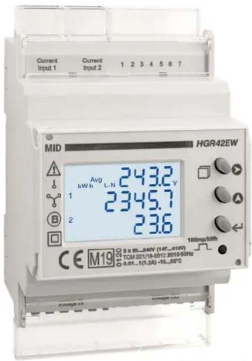
Split Load Three Phase easywire® Multifunction DIN Rail Energy Meter (MID Certified)
● Four module DIN rail mounted
● Energy pulse LED / High definition white backlit LCD display
- 2 x Inputs from easywire® Current Transformers
● Three phase network compatible
● Independently programmable CT ratios (Load 1 and Load 2)
● Programmable voltage transformer ratio
● True RMS measurement
- MID B+D Certified
● Simple programming & operation / auto or manual page scrolling
● 2 x Pulse outputs and Modbus communication or Mbus
● Voltage OUT connector for daisy-chaining up to 32 meters from one supply
MID

Product Description
The HGR42EW series is part of the easywire ^® family of meters, designed to save up to 90% installation time compared to a standard meter and current transformer installation.
The meters contain two 3 Phase metering circuits in one case, and accept inputs from two separate easywire ^® 3 Phase current transformers while still utilizing the same voltage reference.
This MID approved, 4 module DIN rail mounted multifunction energy meter, is suitable for monitoring energy consumption and other electrical parameters in industrial and commercial applications. This series is particularly suited for use in split-load lighting and power boards, in three phase applications, and have been certified for billing purposes.
A high efficiency white backlit LCD display provides a clear indication of measured values in all light conditions. Front push-buttons allow user access to the display page required. The meter is available in two versions:-
- With two pulse outputs and RS485 Modbus communication.
- With two pulse outputs and Mbus communication
MID APPROVED FOR BILLING APPLICATIONS Measuring Instruments Directive
Displayed Parameters
Voltage - L-L, L-N and average
Current - Per phase and average (LOAD 1 and LOAD 2)
Power Factor - per phase and average
Frequency
Power - Active, Reactive and Apparent (per phase and total)
Power Max. demand - Active and apparent power.
Energy - Active, reactive and apparent (per load and total)
| Communications Part Number | |
| Split Load Input with RS485 Modbus Output and Two Pulse Outputs kWh (1 per circuit) | HGR42EWC |
| Split Load Input with Mbus Output and Two Pulse Outputs kWh (1 per circuit) | HGR42EWMB |
Display
| Display Type LCD, high definition with white back-light | |
| Digit height 6.35mm (displayed parameter) | |
| Page scrolling Manual by front key / or auto scroll mode | |
| Displayed parameters and accuracies Voltage 0.5% | of full scaleCurrent 0.5% of full scaleFrequency 0.1% of full scale (L-N >20V)Power factor 1% of unityActive power 1%Reactive power 1%Apparent power 1%Active Energy Class 1, Class B (IEC/EN62053-21, IEC/EN50470)Reactive Energy Class 2 (IEC/EN62053-23) |
| Energy maximum display | 9999999 |
| Resolution | 0.01K, 0.1K, 1K, 0.01M, 0.1M (depending on CT ratio & VT ratio) |
Programming
| Parameters that can be changed using programming menuNOTE: Once Programming Mode Is entered The values in red will be locked out after 15 Mins. No further adjustment is possible without return to factory. | CT Primary currentVT primary voltageVT secondary voltageCommunication addressCommunication speed (Baud)Communication ParityCommunication number of stop bitsBack-light time-out periodDemand period (for integration)Pulse durationPulse output (kWh)Reset to Factory DefaultReset Energy and Maximum DemandReset Active EnergyReset Reactive EnergyReset Apparent EnergyReset Maximum CurrentReset Maximum Active PowerReset Minimum Active PowerReset Maximum Reactive PowerReset Minimum Reactive PowerReset Maximum Apparent Power |
| Programming access | Password protected (user selectable) |
| Memory retention | Non volatile memory |
Input
| Connection Three phase four wire | |
| Input voltage range 3 x 100...240V (L - N), | 3 x 173...415V (L - L) |
| Voltage Rated Burden <8VA | |
| Nominal current input 2 xeasywire | ^ - 1A (330mV) |
| Max current (Imax)easywire | ^ - 1.2A (396mV) |
| Current Rated Burden N/A -easywire | ^ input |
| Starting current 2mA (0.66mV) | |
| Short time overcurrent 30 x Imax to IEC/EN62053-21 - 23 | |
| Impulse voltage withstand 6kV 1.2/50μS 0.5J | |
| AC voltage withstand 4kV 50Hz for 1 min | |
| CT primary current 5...6000A | |
| VT primary voltage 100...600V | |
| Frequency 50Hz | |
| Current distortion factor According to IEC/EN50470 | |
Auxiliary Supply
| Voltage range | Self supplied from measuring input |
| Operating frequency See input section | |
| Power consumption | See input section |
Outputs
| Energy pulses | |
| Number of pulse outputs | 2 |
| Pulse output function | kWh |
| Pulse output type | 1 |
| Pulse output Max. current | 100mA |
| Pulse output voltage range | 5...27VDC |
| Pulse duration | 100ms...2s |
| Pulse resolution | 0.01K, 0.1K, 1K, 0.01M, 0.1M (depending on CT ratio & VT ratio) |
| Communication - Modbus Version | |
| Communication type RS485 | |
| Communication protocol | Modbus |
| Address | 1...255 |
| Number of bits | 8bits |
| Parity | None, odd, even |
| Baud rate | 300, 600, 1200, 2400, 4800, 9600, 19200 |
| Required response time to request | ≤100ms |
| Number of meters connected on the bus | 32 (up to 255 with RS485 repeater) |
| Max distance from Master device | 500M |
Insulation
| Installation category III | |
| Pollution degree 2 | |
| Insulation voltage rating 300V (L-N) |
Environmental Conditions
| Reference temperature 23°C ±2°C | |
| Specified temperature operating range -10°C...+55°C | |
| Storage temperature -20°C...+75°C | |
| Relative humidity 0...85%, non condensing | |
| Mechanical environment M1 | |
| Electromagnetic environment E2 |
Mechanical
| Housing | |
| Housing 4 module DIN 43880 | |
| Mounting Snap-on 35mm rail | |
| Tamper sealing | Meter housing (by means of a tamper evident seal). Sealable terminal covers. |
| Housing material | Self-extinguishing polycarbonate (UL94 V-0) |
| Protection degree (IEC/EN60529) | IP20 (terminals), IP54 (front of housing) |
| Weight | <210g |
| Termination | |
| Current input terminal type | 2 x RJ45 |
| Max. wire size | N/A |
| Voltage input terminal type | Pluggable terminal block - Screw clamp type |
| Max. wire size | 2.5mm^2 |
| Voltage output terminal type | Pluggable terminal block - Screw clamp type |
| Max. wire size | 2.5mm^2 |
| Communication output (RS485 and Pulse) | Pluggable terminal block - Screw clamp type |
| Max. wire size | 1.5mm^2 |
Conformity
| Electromagnetic compatibility | IEC/EN61326-1, IEC/EN55011 Class A, IEC/EN61000-4-2, -3, -4, -5, -6, -8, -11IEC/EN50470-1/3 |
| Accuracy and functionality | IEC/EN50470-1/3, IEC/EN62053-21, IEC/EN62053-23, DIRECTIVE 2014/32/EU |
| Safety | IEC/EN61010, IEC/EN62053-31 |
Wiring Diagrams
Note: # All fuse types : Class CC UL type fast acting 600V
Max. 3A (Actual rating is dependent on the number of meters connected to the voltage supply and must be determined during system design).
3 Phase 4 Wire - 2 CT

flowchart
graph TD
    A["CT Input"] --> B["RS485 NC PULSE OUTPUT"]
    B --> C["Voltage I/P"]
    B --> D["Voltage OP"]
    C --> E["L1"]
    D --> F["L2"]
    E --> G["LOAD"]
    F --> G
    style A fill:#f9f,stroke:#333
    style B fill:#ccf,stroke:#333
    style C fill:#cfc,stroke:#333
    style D fill:#fcc,stroke:#333
    style E fill:#ffc,stroke:#333
    style F fill:#cfc,stroke:#333
    style G fill:#fcc,stroke:#333
Dimensions

Model Selection Table
| Communications Part Number | |
| Split Load Input with RS485 Modbus Output and Two Pulse Outputs kWh (1 per circuit) | HGR42EWC |
| Split Load Input with Mbus Output and Two Pulse Outputs kWh (1 per circuit) | HGR42EWMB |

Brand : HAGER
Model : JKD250MID
Category : Energy meter