X-10 Type 1F - Lock Dormakaba - Free user manual and instructions
Find the device manual for free X-10 Type 1F Dormakaba in PDF.


| Product Type | Electronic Door Lock |
| Model | X-10 Type 1F |
| Brand | Dormakaba |
| Material | Zinc alloy, stainless steel |
| Exterior Dimensions | 120 x 60 x 40 mm |
| Interior Dimensions | 120 x 60 x 40 mm |
| Weight | 0.8 kg (complete set) |
| Power Supply | 4 x AA alkaline batteries (6V DC) |
| Battery Life | Up to 1 year under normal use |
| Operating Temperature | -20°C to 60°C |
| User Capacity | Up to 100 users |
| Access Methods | PIN code, RFID card, mechanical key override |
| Locking Mechanism | Motor-driven deadbolt |
| Finish | Satin nickel |
| Certifications | EN 14846, EN 1634 |
| Installation | Standard 50mm backset, adjustable for 60-70mm door thickness |
| Maintenance | Clean with soft damp cloth; no solvents |
| Safety Features | Anti-tamper alarm, auto-lock function, low battery warning |
| Spare Parts | Batteries, RFID cards, mounting screws available |
| Repair | Replaceable motor unit, circuit board |
| Warranty | 2 years |
| Compliance | CE, RoHS |
| Language Support | English, French, German |
Frequently Asked Questions - X-10 Type 1F Dormakaba
User questions about X-10 Type 1F Dormakaba
0 question about this device. Answer the ones you know or ask your own.
Ask a new question about this device
Download the instructions for your Lock in PDF format for free! Find your manual X-10 Type 1F - Dormakaba and take your electronic device back in hand. On this page are published all the documents necessary for the use of your device. X-10 Type 1F by Dormakaba.
USER MANUAL X-10 Type 1F Dormakaba
INSTALLATION INSTRUCTIONS

natural_image
Close-up of a metallic cylindrical component with a textured inner ring and a black square top (no text or symbols visible)X-10™
Type 1F HIGH SECURITY ELECTRONIC LOCK
TABLE OF CONTENTS
Introduction.... 1
Basic Tools and Materials Needed .... 1
Lock Parts for Installation .... 1
Installation Kit Contents....2
Template 3
Preparation for New Installation of the Lock....4
Installation....5
Preliminary Lock Installation....5
Cutting the Tubes....5
Installation of the Lock....6
Installation of the Dial Ring....7
Installation of the Cables 7
Installation of Generator Cable and Cable Guides 8
Installation of the Dial Ring Cover 9
Cutting and Installing the Spindle 9
Installation of the Dial Hub and Dial 10
Final Installation....12
Installation Completion Checklist....12
Open and Close the X-10 Lock (Factory Combination)....13
Appendix A - Tube Retainer Positions....14
Appendix B - Cable Routing Diagrams......15
Document Number 519.0112
Rev. B - 10/13
KARA®
MAS
Kaba Mas LLC
749 W. Short Street,
Lexington, KY 40508 USA
Phone: 859-253-4744 FAX: 859-255-2655
Technical Support: 800-950-4744
www.kaba-mas.com
Please read all instructions before you install and use your Model X-10™ lock. This will help you avoid unnecessary costs and issues resulting from improper installation.
BASIC TOOLS AND MATERIALS NEEDED
- Small Phillips head screwdriver (#0)
- Medium Phillips head screwdriver (#1/#2)
- Standard hacksaw (32 teeth/inch)
- Six inch metal scale or ruler
Recommended, but not required:
- Small flat file
- Small vise
- Torque screwdriver (30 inch-pound capacity), or
- Standard torque wrench with screwdriver bits
Note: See table of recommended torques for the various X-10 lock screws.
All other necessary tools and materials are provided.
| TABLE OF RECOMMENDED TORQUES FOR THE VARIOUS X-10 LOCK SCREWS | |||
| Applications P/N Screw | Size Torque (In.Lb.) | ||
| Dial Ring Mounting 105034 8-32 17.0 to 20 | 0 | ||
| Dial Ring Cover 105034 8-32 17.0 to 20.0 | |||
| Lock Case Mounting 105046/105195 1/4-20 | 25.0 to 30.0 | ||
| Spindle Screw 205056 6-32 9.0 to 11.0 | |||
X-10 LOCK PARTS FOR INSTALLATION
- Lock Assembly
- Dial Ring Assembly
- Dial Assembly
- Spindle
- Dial Hub Assembly
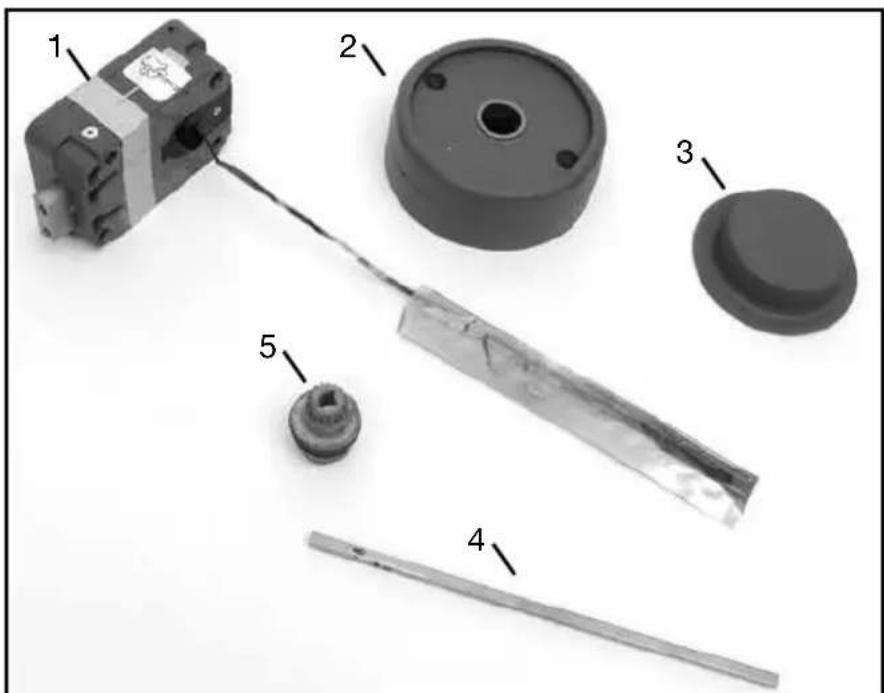
Figure 1: X-10 Lock Parts
INSTALLATION KIT CONTENTS

Figure 2 - X-10 Installation Kit
- Rubber Vise Clamp
- Saw Blade (52 teeth/inch)
- Saw Handle
- Tube Deburr Stone
- Outer Tube
- Inner Tube
- Dial Ring Mounting Screws (2)
- Lock Case Mounting Screws (Two sets; 4 each, English and Metric)
- Stick-on Cable Guides (3)
- Zebra Connector & Zebra Connector Housing*
- Lubricant (Lubriplate)
- Dial Hub Locating Gauge
- Hex Key (5/64")
- Spindle Screw
*The Zebra Connector and Zebra Connector Housing are assembled at the factory but may come apart during shipment.
TEMPLATE
A template is provided as an aid for locating, drilling, and tapping the lock case and dial ring mounting screw holes relative to the spindle hole. Since the lock is designed to fit most industry standard container lock mounting screw hole patterns, the need to use this template should be minimal.

Figure 3: X-10 Drill Template
Note: The above template is NOT Actual Size. Do Not Use for locating, drilling, and tapping the lock mounting holes. A Template of actual size is included with the lock installation kit. Make sure to deburr the spindle hole and opening.
PREPARATION FOR NEW INSTALLATION OF THE LOCK
- Use the template to establish the correct locations of all mounting holes for the lock case and the dial ring, when necessary.
- The lock case mounting screws require drilled and tapped 1/4-20 screw holes. (M6X1, if Metric)
- The dial ring mounting screws require drilled and tapped #8-32 screw holes.
- The spindle hole must be 3/8 inch diameter, minimum.

Figure 4 - Tube-Cable Assembly Relationships
PRELIMINARY LOCK INSTALLATION
- Deburr spindle hole and opening.
- Feed Lock Cable through spindle hole.
- Loosely attach the lock case to the container wall with the four mounting screws.
- Tighten the lock case mounting screws to hold the lock case in place. (See Figure 5.)
CUTTING THE TUBES

Figure 5 - Tighten Mounting Screws
Warning: The end of the large tube that is to be discarded must be from the plain (unflared) end of the tube. The end of the small tube that is to be discarded must also be from the plain (unnotched) end of the tube.
-
Make sure that the outer tube is properly placed over the lock case tube retainer.
-
While holding the outer tube firmly in its seated position, use a 6 inch scale or ruler to measure 5/16 inch from the
container wall and mark the outer tube at this length.
-
Remove the lock case from the container and remove the outer tube for cutting.
-
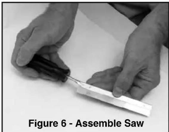
Assemble the saw blade and wooden saw handle provided. To assemble the saw, grip the saw frame in a vise, just below the neck. Drive the handle fully onto the neck. (See Figure 6.) This will reduce the tendency of the handle to turn on the saw frame when sawing.
natural_image
Close-up of hands assembling a small mechanical component, labeled as Figure 6 - Assemble Saw (no other text or symbols visible)Note: This saw is intended only for cutting the tubes. A standard hacksaw should be used to cut the spindle.
- Insert the tube into the rubber vise clamp (provided), with the mark just beyond the clamp. Then firmly clamp the rubber vise clamp in a vise. (See Figure 7.) Use the saw to cut the tube where marked.

natural_image
Close-up of a hand using a black vise to adjust or install a mechanical component (no visible text or symbols)Figure 7 - Cut Tube Using Vise
Note: Be careful to keep the cut as straight as possible. Remember the saw only cuts when pushing. Trying to cut while pulling may pull the handle off of the saw blade.
- The inside and outside of the tubes must be deburred after cutting. Use the stone provided for this purpose. Make sure there are no sharp edges on either tube (inside and outside) that will damage the 7. Install the inner tube on the lock case. Feed the cables through the outer tube and install the outer tube on the lock case. Measure and mark the inner tube to be 1/16 to 1/8 inch longer than the outer tube. (See Figure 9.) Remove the inner tube and cut by the same method as described in Step 5.

natural_image
Close-up of hands performing a deburr tube manipulation technique (no text or symbols visible)
cables. (See Figure 8.)
Warning: The end of the outer tube that is to be discarded must be from the plain (unflared) end of the tube. The end of the inner tube that is to be discarded must also be from the plain (unnotched) end of the tube.
Figure 9 - Inner and Outer Tubes
INSTALLATION OF THE LOCK
- Place the inner tube into the lock case tube retainer. Make sure the cutout in the tube aligns with the cables and allows the tube to seat completely in the tube
retainer. (See Figure 10.)
-
Feed the cables through the outer tube from the flared end. Seat the tube into position on the tube retainer on the back of the lock case. (See Figure 4.) Be careful to keep the cables pulled taut while seating the tube to avoid pinching and damaging them.
-
Carefully guide the outer tube (keeping it in place on the tube retainer) through the container wall so the outer tube and the cables are easily accessible at the outside wall of the container, retracting the bolt if necessary.

natural_image
Close-up of a mechanical component with a cylindrical rod inserted into a housing, showing mounting holes and a wire (no text or symbols visible)Figure 10 - Seat Inner Tube in Retainer
-
Loosely attach the lock case to the container wall using the lock case mounting screws.
-
Tighten the lock case mounting screws to the specified torque on page 1. (Also see Figure 5.)
INSTALLATION OF THE DIAL RING
- Remove the two screws from the dial ring assembly cover and remove the cover.
Note: Make sure the tubes are projecting through the container as shown in Figure 9 on the previous page. If not, the tubes are not seated properly in the lock or they were not cut to the proper length. Correct the problem before proceeding.
- If necessary, rotate the tube retainer in the dial ring so the cables come through the notch in the tube retainer. See Appendix A for details.
- Feed the cables through the tube retainer on the dial ring and place the dial ring over the end of the tubes. Make sure the tubes are seated in the tube retainer on the dial ring.
- Attach the dial ring to the container with the dial ring mounting screws and tighten to the specified torque. (See Page 1.)
INSTALLATION OF THE CABLES
- Open the ZIF (Zero Insertion Force) seal cover and move the ZIF connector locking actuators outward to their open position. (See Figures 11 and 12.)
- Plug the cables into the ZIF connectors with the bright metal tabs facing toward the circuit board. Push the cables into the connectors as far as they will go.


Figure 11 - Open ZIF Seal Cover Figure 12- Closed & Open ZIF Connectors
- Close the ZIF locking actuators to lock the cables in place.
- Close the ZIF seal cover. When closing, be sure the tenons in the seal cover align with the holes of the seal cover.

Figure 13 - LCD and ZIF Connectors
INSTALLATION OF GENERATOR CABLE AND CABLE GUIDES
- Place the generator cable into the dial ring housing recess containing a post used for positioning the cable. (See diagrams in Appendix B.) The hole in the cable must be positioned over the post on the dial ring, and the five gold tabs must be visible.
- The Zebra connector and Zebra connector housing are assembled at the factory but may come apart during shipment. If so, insert the Zebra connector into the Zebra connector housing before proceeding.
CAUTION: The Zebra connector is an electrical connector. Keep it clean!
-
Place the Zebra connector and connector housing over the generator cable, and press it into the recess. The hole in the Zebra connector housing must be positioned over the post in the dial ring. Be sure the black Zebra connector housing is positioned as shown in Figure 14.
-
Install at least one of the stick-on cable guides in an appropriate position to restrain the cables. (See Figure 15 for possible locations.)
-
Route the cables through the cable guide that was just installed.

Figure 14 - Zebra Assembly
- Depending on the thickness of the container, additional cable guides may be necessary to ensure the cables are held in place. Some possible locations are shown in Figure 15. Install additional guides as needed, and route the LCD and generator cables through them to ensure the cables do not get routed through the "KEEP CLEAR" area, over the Zebra connector, or near where the geared end of the dial hub will project through the dial ring cover.
Caution: See Appendix B for more detail on routing the cables.
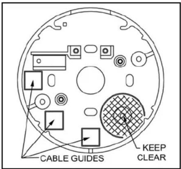
Figure 15 - Cable Guide Locators
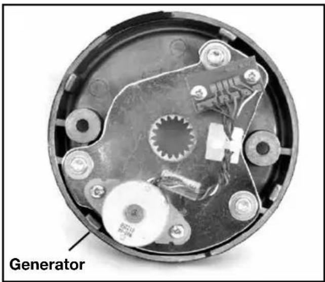
Figure 16 - Dial Ring Cover
INSTALLATION OF THE DIAL RING COVER
- Align the dial ring cover with the dial ring so the generator will seat into the five o'clock position and the four aligning lugs align with the corresponding slots in the dial ring. (See Figures 15 and 16.)
- Carefully slide the dial ring cover into the dial ring.
- Hold the dial ring cover in place and tighten the two dial ring cover mounting screws to the specified torque. (See Page 1.)
CUTTING AND INSTALLING THE SPINDLE
- Slide the spindle into the lock case. Note the square portion of the spindle must be aligned with the square hole in the lock case. Insert spindle screw and tighten.
- Slide the dial hub onto the spindle, turning the hub slightly to align the generator drive gear teeth.
- Partially tighten one setscrew to hold the dial hub in place.
- Mark the spindle flush to the dial hub. (See Figure 17.)
- Loosen the setscrew and remove the hub.
Alternate Method: Instead of removing the hub, you may leave it on, using the hub as a vise to hold the spindle while cutting.
- Remove spindle screw and spindle from lock case prior to cutting. Carefully cut the spindle so that it will be flush to the dial hub after installation.
Caution: The spindle should not extend past the dial hub once installed but may be recessed up to 1/32 inch below the surface of the hub. If it extends past the dial hub, it must be filed to flush. (See Figure 18.)

natural_image
Close-up of a precision tool interacting with a metallic mechanical component (no visible text or symbols)Figure 17 - Mark Spindle Flush to Hub

Figure 18 - Spindle Flush or Recessed
- Remove all burrs from the spindle.
INSTALLATION OF THE DIAL HUB AND DIAL
- Slide the spindle into the lock case. Note that the square portion of the spindle must be aligned with the square hole in the lock case. Insert spindle screw and tighten. (For torque specifications, see Page 1.)
- Apply lubricant to the hub bearing surface. (See Figure 19.)
- Make a bend in the dial hub locating gauge at its midpoint. This will keep it from acting as a spring as the hub is positioned for locking to the spindle.
- Place the Dial Hub Locating Gauge over the spindle and between the dial hub and the bushing in the dial ring cover. This sets up an initial 0.010 inch end play. (See Figure 20.)
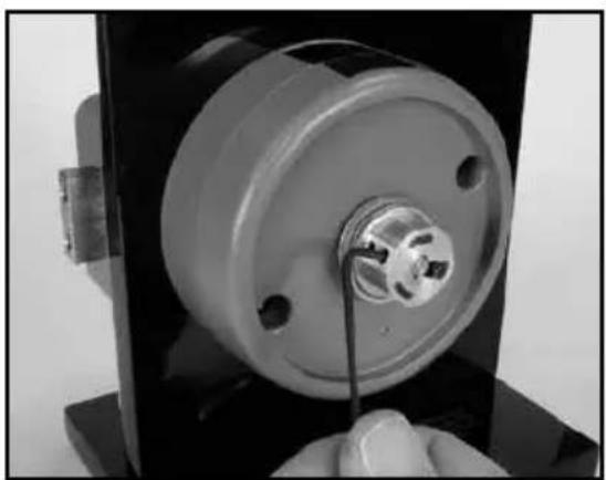
- Tighten the inner setscrew first. Now SECURELY tighten the setscrews in the dial hub to 17-20 inch-pounds of torque (a minimum of 1 inch deflection of the handle of the hex key).
- Remove the dial hub locating gauge.

natural_image
Close-up of hands holding a small mechanical component with a white adhesive tape applied (no visible text or symbols)Figure 19 - Apply Lubricant to Hub

natural_image
Close-up of a mechanical component with a metallic cylindrical housing and a metallic connector (no visible text or symbols)Figure 20 - Place Gauge Between Dial Hub & Bushing
Caution: Tighten in a downward motion in case the hex key should break. (See Figure 21.)
- Apply lubricant to the retaining ring on the dial hub. Position the retaining ring so an equal amount of lubricant is consistently exposed around the hub. Also, apply grease from the lubricant tube to the entire ramp area just inside the back of the dial and to the inner surface of the 5-sided formed clutch spring within the dial. (See Figures 22 and 23.)
Note: Ensure the "C" clip is located in the grove closest to the set screw. The retaining ring gap should be aligned with the setscrews so an equal amount of the retaining ring is exposed around the hub. The dial should slide easily into place on the hub without interference from the retaining ring. (See Figure 24.)
natural_image
Close-up of a mechanical component with a central hub and mounting base, being adjusted by hand (no visible text or symbols)Figure 21 - Tighten Setscrews
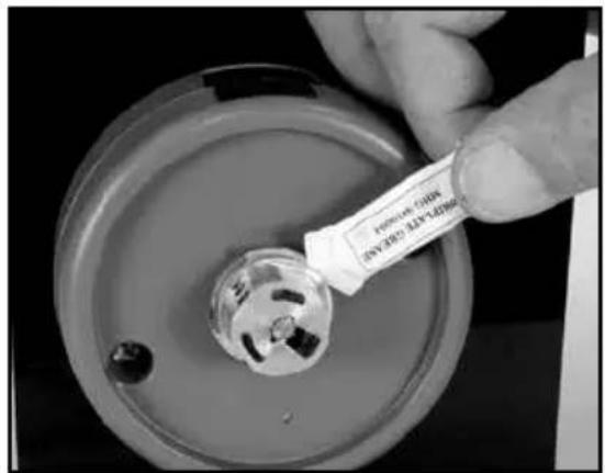
Figure 22 - Apply Lubricant to Ret. Ring

natural_image
Close-up of hands holding a small label labeled 'COAST' inserted into a cylindrical mechanical component (no text or symbols on the object itself)Figure 23 - Apply Lubricant Inside Dial

Figure 24 - Align Retaining Ring
- Ensure that the 5-sided flat spring is fully recessed in the dial with the spring gap aligned with the internal key of the dial. (See Figure 25.)
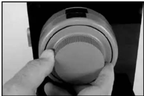
- Carefully align the dial so the 5-sided formed spring matches the flats of the dial hub assembly. Holding the dial square to the spindle, apply pressure to the dial until the retaining ring seats in the dial. (See Figure 26.)
Note: You should not be able to pull the dial away from the dial hub assembly.

natural_image
Top-down view of a mechanical component with radial slots and central hub (no text or symbols visible)Figure 25 - 5-Sided Flat Spring in Dial
natural_image
Close-up of a hand holding a circular object with a textured surface, possibly a device or component (no visible text or symbols)Figure 26 - Apply Pressure to Dial
FINAL INSTALLATION
Warning: Failure to verify that the lock is operational may cause a lockout condition.
- Open the lock using the factory combination. (See Page 13.) Leave the bolt in the fully retracted position.
- Record the 8-digit lock serial number in a secure location if you are the end user. If you are not the end user, allow the end user to remove the serial number sticker from the back of the lock when the container has been placed in use.
- Make sure the bolt is fully retracted.
- Tighten the spindle screw to the torque specifications. (See Page 1.)
INSTALLATION COMPLETION CHECKLIST
- Does the dial turn freely without scraping or binding?
- Have all screws been securely tightened?
- The dial clutch should provide a slip torque of 7 to 25 inch pounds.
- Operate the lock using the preset factory combination of 50-25-50. See the following section: OPEN AND CLOSE THE X-10.
OPEN AND CLOSE THE X-10 (FACTORY COMBINATION)
CW=Clockwise; CCW=Counterclockwise
Note: The viewing angle of the LCD is restricted from either side as a security feature of the lock. This feature restricts viewing of combination dialing by the casual observer.
TO OPEN THE LOCK (Using the Factory Combination):
- Dial left (CCW) until lock is "powered". The lock is considered "powered" when numbers appear on the LCD display screen.
- Continue dialing left (CCW) to the first number of the factory combination, 50. Stop on 50 and pause briefly.
- Dial right (CW) to the second number of the factory combination, 25. Stop on 25 and pause briefly.
- Dial left (CCW) to the first number of the factory combination, 50. Stop on 50 and pause briefly.
- Dial right (CW). After OP with a right arrow (OPen right) is displayed, dial to the right to retract the lock bolt.
Note: If at any time the dial remains stationary for more than 40 seconds, the lock will reset (LCD will go blank) requiring the operator to redial the entire combination.
TO CLOSE THE LOCK:
- Turn Dial to the left (CCW) a minimum of one complete revolution to extend the bolt. Wait 3 seconds.
- Turn Dial to the right (CW) a minimum of one complete revolution to ensure that it is locked.
Note: The Dial should turn freely in either direction without catching or binding when the bolt is extended and the container is locked.
APPENDIX A TUBE RETAINER POSITIONS
The tube retainer must be positioned so the cables come through the notch in the retainer.
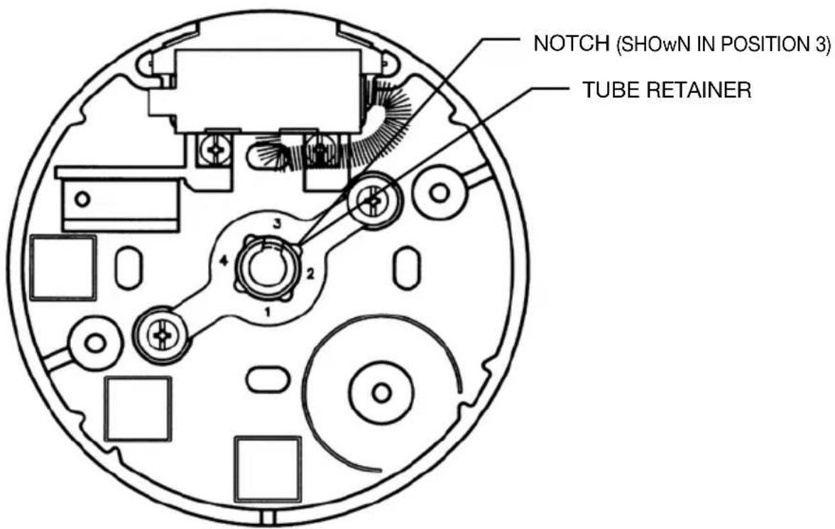
While facing the outside of the container, position the notch in the tube retainer as follows:
| Bolt Position Notch Position | |
| Up | 1 |
| Left | 2 |
| Down | 3 |
| Right | 4 |
APPENDIX B CABLE ROUTING DIAGRAMS
Refer to the following table and diagrams for suggested cable routing paths to avoid pinching or rubbing of cables. Choose the diagram that most closely represents the thickness of the container door. Ensure the cables are routed so that they do not get pinched by the generator.
| Door Thickness Cable | Exit Position Bolt Position | |
| 4 1/2" | 3 | Down |
| 2 1/2" | 1 | Up |
| 3/4" | 2 | Left |

natural_image
Diagram of an electronic device interior showing wiring and components (no text or labels)Dia. 1: 3/4 inch door, Cable exit position 2, Bolt Left.
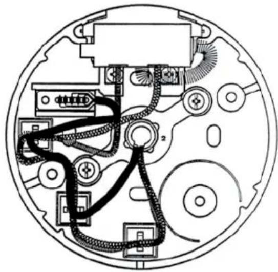
natural_image
Cross-sectional diagram of a mechanical or electronic device with internal components and wiring (no text or labels)Dia. 2: 2 1/2 inch door, Cable exit position 1, Bolt Up.

natural_image
Cross-sectional diagram of a circular electronic device with internal components and wiring (no text or labels)Dia. 3: 4 1/2 inch door, Cable exit position 3, Bolt Down.
Notice: The information in this manual is subject to change without notice and does not represent a commitment on the part of Kaba Mas. Kaba Mas shall not be liable for technical or editorial errors or omissions contained herein; nor for incidental or consequential damages resulting from the furnishing, performance or use of this material.
© 2002-2013 Kaba Mas LLC
All rights reserved.
KARA®
MAS
Kaba Mas LLC
749 W. Short Street,
Lexington, KY 40508 USA
Phone: 859-253-4744 FAX: 859-255-2655
Technical Support: 800-950-4744
www.kaba-mas.com
- INSTALLATION INSTRUCTIONS
- TABLE OF CONTENTS
- Introduction.... 1
- Installation....5
- Appendix A - Tube Retainer Positions....14
- Appendix B - Cable Routing Diagrams......15
- BASIC TOOLS AND MATERIALS NEEDED
- Recommended, but not required:
- X-10 LOCK PARTS FOR INSTALLATION
- INSTALLATION KIT CONTENTS
- TEMPLATE
- PREPARATION FOR NEW INSTALLATION OF THE LOCK
- PRELIMINARY LOCK INSTALLATION
- CUTTING THE TUBES
- INSTALLATION OF THE LOCK
- INSTALLATION OF THE DIAL RING
- INSTALLATION OF THE CABLES
- INSTALLATION OF GENERATOR CABLE AND CABLE GUIDES
- INSTALLATION OF THE DIAL RING COVER
- CUTTING AND INSTALLING THE SPINDLE
- INSTALLATION OF THE DIAL HUB AND DIAL
- FINAL INSTALLATION
- INSTALLATION COMPLETION CHECKLIST
- OPEN AND CLOSE THE X-10 (FACTORY COMBINATION)
- TO OPEN THE LOCK (Using the Factory Combination):
- TO CLOSE THE LOCK:
- APPENDIX A TUBE RETAINER POSITIONS
- APPENDIX B CABLE ROUTING DIAGRAMS
Brand : Dormakaba
Model : X-10 Type 1F
Category : Lock