
QRAD200E - Radiator DIMPLEX - Free user manual and instructions
Find the device manual for free QRAD200E DIMPLEX in PDF.


| Product Type | Electric Radiator |
| Model | QRAD200E |
| Brand | Dimplex |
| Power Output | 2000 W |
| Voltage | 220-240 V ~ 50 Hz |
| Dimensions (H x W x D) | 680 x 550 x 95 mm |
| Weight | 12.5 kg |
| Heating Element | Oil-filled radiator |
| Number of Elements | 11 |
| Thermostat Control | Adjustable thermostat with frost protection |
| Timer Function | 24-hour programmable timer |
| Overheat Protection | Yes |
| Tip-Over Switch | Yes |
| Energy Efficiency Class | Class D |
| Mounting Type | Free-standing or wall-mounted (brackets included) |
| Noise Level | Silent operation |
| Maintenance | Wipe with a damp cloth; do not use abrasive cleaners |
| Spare Parts Availability | Thermostat, feet, castors, wall brackets available from Dimplex service |
| Warranty | 2 years |
Frequently Asked Questions - QRAD200E DIMPLEX
User questions about QRAD200E DIMPLEX
0 question about this device. Answer the ones you know or ask your own.
Ask a new question about this device
Download the instructions for your Radiator in PDF format for free! Find your manual QRAD200E - DIMPLEX and take your electronic device back in hand. On this page are published all the documents necessary for the use of your device. QRAD200E by DIMPLEX.
USER MANUAL QRAD200E DIMPLEX
Installation and Operating
natural_image
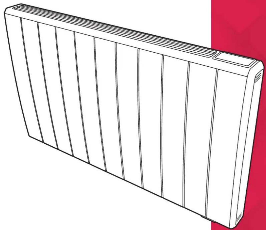
Line drawing of a rectangular electronic device with vertical fins, shown in isometric view against a red background (no text or symbols)Q-Rad Electric Radiator
Models: QRAD050E / QRAD075E / QRAD100E
QRAD150E / QRAD200E

Warnings in this document are identified by a warning triangle against a grey background.
Keywords at the start of a warning indicate the type and seriousness of the ensuing risk if measures to prevent the risk are not taken.
The following keywords are defined and can be used in this document:
o DANGER indicates a hazardous situation which, if not avoided, will result in death or serious injury.
o WARNING indicates a hazardous situation which, if not avoided, could result in death or serious injury.
- CAUTION indicates a hazardous situation which, if not avoided, could result in minor to moderate injury.
- NOTICE is used to address practices not related to personal injury.
CAUTION
FAILURE TO FOLLOW THESE INSTRUCTIONS MAY CAUSE INJURY AND/OR DAMAGE AND MAY INVALIDATE YOUR GUARANTEE
IMPORTANT SAFETY ADVICE
When using electrical heaters, basic precautions should always be followed to reduce the risk of fire, electrical shock, and injury to persons, including the following:
IMPORTANT - The wall bracket supplied with the heater must be used.
IMPORTANT - All packaging should be disposed of in an appropriate manner.
OVERHEATING WARNING
WARNING - In order to avoid overheating, do not cover or obstruct the heater. Do not place material or garments on the heater, or obstruct the air circulation around the heater, for instance by curtains or furniture, as this could cause overheating and a fire risk. NEVER cover or obstruct in any way the heat outlet slots at the top of the heater or the air outlet slots in the base of the heater.

WARNING - THE SURFACES ON THIS HEATER CAN BE HOT.
The heater carries a warning 'DO NOT COVER' to alert the user to the risk of fire that exists if the heater is accidentally covered.
CAUTION - Some parts of this product can become very hot and cause burns. Particular attention has to be given where children and vulnerable people are present.
For your safety this heater is fitted with a thermal cut-out. In the event that the product overheats for some reason, the cut-out prevents excessive temperatures on the product by cutting the power to the heater. Once the heater has cooled down, it will reset automatically, it will continue to cycle on and off automatically until the reason for overheating is removed.
The display screen may flash red to indicate the product has overheated. To reset the display, remove the obstruction and hold Enter for 10 seconds.
SUITABLE APPLICATIONS
WARNING - This heater is suitable for normal dwelling purposes and should not be used in any other type of environment. This product should only be used in the country where it was purchased from by a recognised commercial retailer. Do not use outdoors.
SERVICING AND REPAIRS
WARNING - Servicing and product repairs should only be undertaken by the manufacturers approved service agent or a similarly trained or qualified person, using only exact manufacturer approved spare parts.
PLEASE NOTE: Household dust, lit cigarettes, candles and oil burners, combined with the convection effect of electric heaters can cause significant soot deposits to build up on the surface directly above and to the sides of the heater. This is not a fault of the heater. Extensive burning of candles or smoking in the operating environment of this product can produce heavy discolouration within a few months of use.
OPERATING WARNINGS
IMPORTANT: Remember to observe all safety warnings and precautions when operating the heater on the automatic or timer modes, either attended or unattended since a fire risk exists when the heater is accidentally covered, obstructed or displaced.
CAUTION: Do not use if either of the heater's mains power leads become damaged. If the supply cord is damaged it must be replaced by the installer or an approved Dimplex service partner.
Do not sit or stand on the heater.
Ensure minimum clearances between the heater and other objects / surfaces are maintained.
ELECTRICAL INSTALLATION
WARNING - Minimum clearances and IP zone requirements must be adhered to in accordance with the current wiring regulations.
Mains cables are not provided with this heater.
WARNING - The electrical installation of this heater must be carried out by a suitably qualified or trained electrician, and be in strict accordance with current wiring regulations BS 7671. DO NOT INSTALL IF PRODUCT IS DAMAGED.
The supply must be connected via a switched fused spur with a fuse rated suitably for the appliances flex.
Failure to follow these instructions will mean that the manufacturer's instructions have not been adhered to. THERE ARE NO EXCEPTIONS.
The wires in this mains lead are coloured in accordance with the following code:
GREEN AND YELLOW: EARTH
BLUE: NEUTRAL
BROWN: LIVE
• This heater must be earthed
• Not suitable for connection via a plug top
- Do not locate the heater immediately above, below or in front of a fixed electrical point i.e. socket outlet.
The heater is fitted with a length of flexible cable type H05VV-F size 3 × 1.0mm^2 for 500W to 2kW and 3 × 1.5mm^2 on 3.0kW models for connection to the fixed wiring of the premises through a suitable connection box positioned adjacent to the heater. A means for disconnection must be incorporated in the fixed wiring of the premises in accordance with the current wiring regulations. The supply circuit to the heater must incorporate a double pole isolating switch having a contact separation of at least 3mm. Products that are supplied without a plug are for installation into the fixed wiring of the property, via a suitable double pole switched fused spur with a fuse rated suitably for the appliances flex. Typical fuse ratings for 230V equipment - Up to 700W = 3A, over 700W = 13A.
In installation the supply cord may be cut to the appropriate length for the electrical connection point. Excess cable should not be inserted and stored behind the heater.
CHILD SAFETY
WARNING - Fixing kit screws are a potential choking hazard.
WARNING - This appliance is not intended for use by persons (including children) with reduced physical, sensory or mental capabilities, or lack of experience and knowledge, unless they have been given supervision or instruction concerning use of appliance by a person responsible for their safety.
This appliance can be used by children from 8 years and above and persons with reduced physical, sensory or mental capabilities or lack of experience and knowledge if they have been given supervision or instruction concerning use of the appliance.
Children shall not play with the appliance.
Cleaning and user maintenance shall not be made by children without supervision.
Children of less than 3 years should be kept away unless continuously supervised.
Children aged from 3 years and less than 8 years shall only switch on/off the appliance provided that it has been placed or installed in its intended normal operating position and they have been given supervision or instruction concerning use of the appliance in a safe way and understand the hazards involved.
Children aged from 3 years and less than 8 years shall not regulate and clean the appliance or perform user maintenance.
WARNING - KEEP BATTERIES OUT OF REACH OF CHILDREN
WARNING - Packaging should be disposed of responsibly as the EPS used could be a potential choking hazard for children.

This document is customer property and is to remain with this unit.
These instructions do not cover all the different variations of systems nor does it provide for every possible contingency to be met in connection with installation.

WARNING: EARTHING
This appliance must be earthed in accordance with the manufacturers recommendations and in accordance with IEE regulations for electrical equipment.
Failure to adequately earth the appliance can result in electrical shock causing severe personal injury or death.

WARNING: HAZARDOUS VOLTAGE
Disconnect all power to unit before installing or servicing.
Hazardous voltage can cause severe personal injury or death.

WARNING: ACCESS TO LIVE PARTS
If the supply cables to the appliance are damaged in anyway, they must be immediately replaced by a competent person in order to avoid electrocution which could cause severe personal injury or death.
Energy Related Product Directive
Product information according to Ecodesign Regulation (EU) 2015/1188
| Model Identifier(s): | QRAD050E | QRAD075E | QRAD100E | QRAD150E | QRAD200E | |
| Heat Output | ||||||
| Nominal heat output | Pnom | 0.50kW | 0.75kW | 1.00kW | 1.50kW | 2.00kW |
| Minimum heat output (indicative) | Pmin | N.A N.A | N.A | N.A N.A | ||
| Maximum heat output | Pmax,c | 0.50kW | 0.75kW | 1.00kW | 1.50kW | 2.00kW |
| Auxiliary electricity consumption | ||||||
| At nominal heat output | elmax | 0.00 | 0.00 | 0.00 | 0.00 | 0.00 |
| At minimum heat output elmin | 0.00 | 0.00 | 0.00 | 0.00 | 0.00 | |
| In standby mode | eISB | <0.0005 | <0.0005 | <0.0005 | <0.0005 | <0.0005 |
| Type of heat output / room temperature control | ||||||
| Electronic heat charge control with room and / or outdoor temperature feedback | Yes | |||||
| Other control options | ||||||
| Room temperature control, with open window detection | Yes | |||||
| With adaptive start control | Yes | |||||
Contact details
Glen Dimplex Heating and Ventilation
Millbrook House, Grange Drive, Hedge End, Southampton, SO30 2DF
Tel: 0344 879 3588
This product meets the Ecodesign requirements for an electric storage local space heater. Commission Regulation (EU) 2015/1188.
Technical Details
| Model Identifier(s): | QRAD050E | QRAD075E | QRAD100E | QRAD150E | QRAD200E | |
| Height (mm) 546 546 546 546 546 | ||||||
| Width (mm) 513 513 675 756 918 | ||||||
| Depth (mm) 105 105 105 105 105 | ||||||
| All Models | |
| Controls | Digitally controlled, Electronic Thermostat accurate to (±0.2°C)Timer modes:7 Day Programmable User Timer, Out All Day, Home All Day.Continuous heat modes:Eco, Manual, Frost Protect, RunbackAdditional Modes:Away, Boost, Setback |
| Controller UI | • Graphical display with RGB backlight• Capacitive buttons with audio feedback• User replaceable battery (Coin-Type)• Open window detection, Adaptive-start, Advance time period• Wide SP range (7-30°C)• Bluetooth for software updates• Child Lock & Heater Lock (PIN-based) |
| Construction | • Durable epoxy-polyester powder coated steel casing with louvered forward facing grille• Advanced controls with capacitive sense technology for total flexibility of heating |
| Element Compact, finned, mineral filled sheathed element | |
| Installation • H-frame wall bracket | |
| Safety | • Thermal cut-out. Auto reset type• Overheat detection |
| IP Rating IP24 | |
| Battery | 3V coin cell battery to backup real time clock. Battery life >5 years. |
| Supply | 1.3 metres fitted, 3 core for fused spur installation, 1/N/PE -230-240 V, 50HzClass I, with earth wire |
| Colour / Finish | Metal Chassis, Air Outlet Grille & Control Moulding - Traffic White (RAL 9016) |
| Approvals CE, BEAB | |
| Guarantee 2 years | |
| Country of Origin United Kingdom | |
| Manufacturer | Glen Dimplex Heating & Ventilation(GDC Group Ltd.) |
General
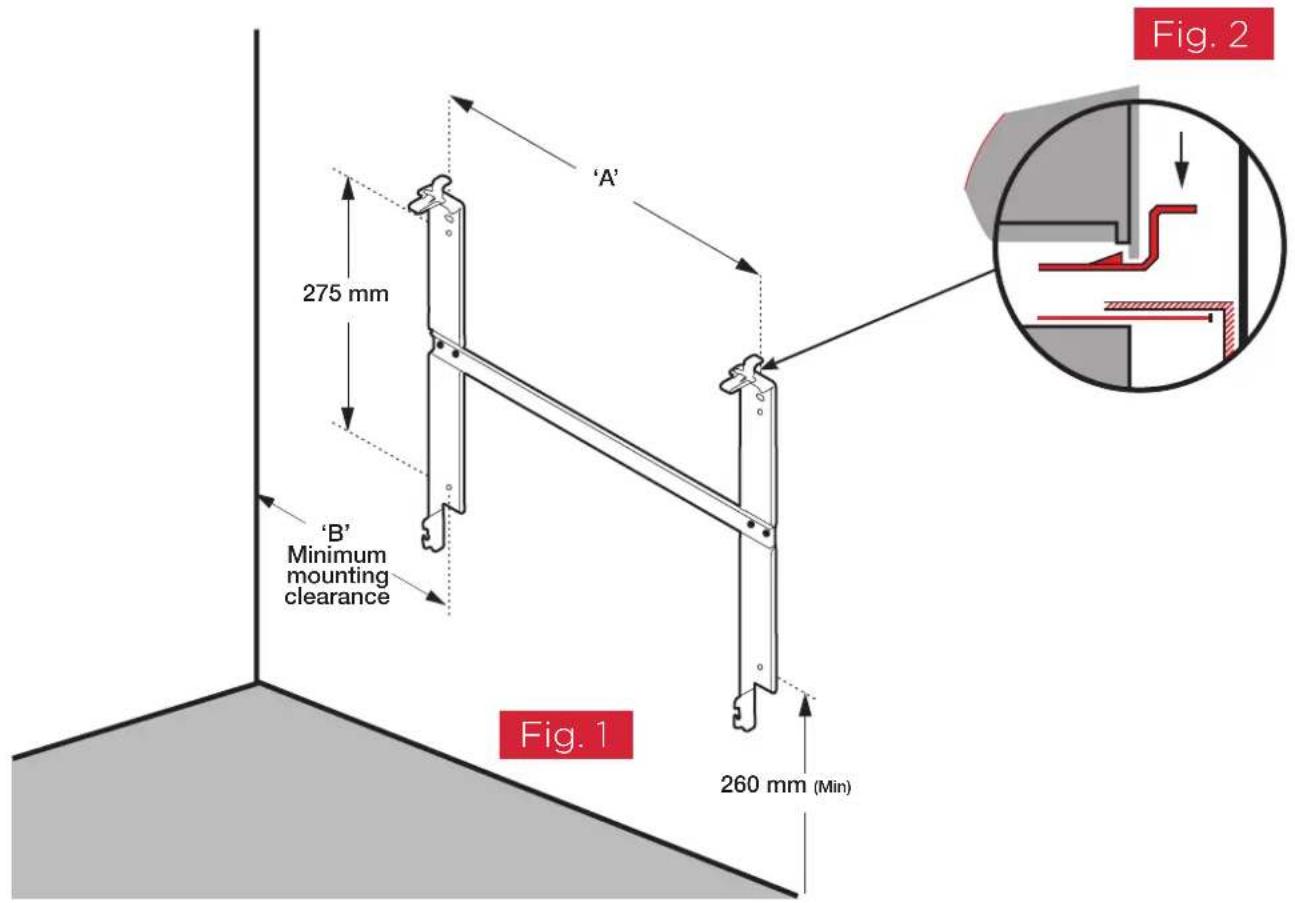
The heater is designed for wall mounting using the wall bracket supplied. It should only be operated when in the upright position as shown - see Fig. 1 and Fig. 2. All models are splash proof to IP24. Before connecting the heater check that the supply voltage is the same as that stated on the heater.
Wall Mounting
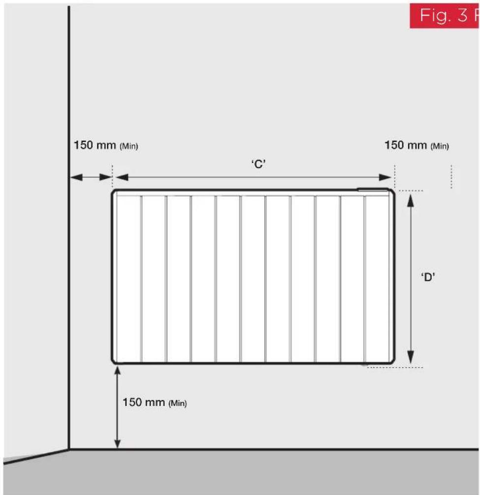
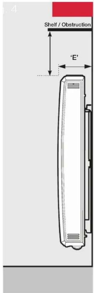
IMPORTANT - The wall bracket supplied with the heater must be used and the heater must be installed in the correct orientation. The fixings should be used to secure the bracket to the particular wall on which the heater will be installed. The heater should be positioned observing the minimum clearances stated around the heater - see Fig. 2, Fig. 3 and Fig. 4.
| MODEL A B C D E | ||||
| QRAD050E 225 294 513 546 105 | ||||
| QRAD075E 225 294 513 546 105 | ||||
| QRAD100E 387 294 675 546 105 | ||||
| QRAD150E 468 294 756 546 105 | ||||
| QRAD200E 630 294 918 546 105 |
To mount the heater to the wall:
- Remove wall mounting bracket from the back of the heater by depressing the spring latch at the side of each bracket - see Fig.2.
- Fix the wall bracket securely to the wall through the four screw holes. Ensure only screw fittings provided are used for the particular wall type.
- Present the heater to the wall bracket and engage bottom slots in the back with bracket hooks.
- Press heater into locked position and ensure the clips on the top are engaged.
- Remove protective film from the user interface
natural_image
Pure vertical lines within a rectangular frame, no text or symbols present
WARNING:
This product is heavy and care should be taken in installation
First Time Power-On
A setup wizard will display when the product is powered on for the first time. This will set the following:
• Time, Date, Daylight Savings Time
- Sound On/Off
For information on using the Heaters controls, refer to page 11. The Heater will then take the User to the Home Screen with the 'Out All Day' Timer Mode active.
Important
During initial heat-up, some odour may be emitted due to the newness of materials used in manufacture. This is normal and will disappear after a short period of use. It is however advisable to keep the room well ventilated.
DCimplex·Control
This product is Dimplex Control capable * * *.
Control and monitor your heating and hot water with Dimplex Control. Group heaters into zones to easily control and track their energy usage. Any time. Anywhere.
Search for Dimplex Control on your device's app store.

natural_image
Red square icon with a white abstract symbol resembling a stylized 'X' or cross (no text or numbers)

*Requires additional hardware. Sold separately. Visit Dimplex.co.uk for more information.
**A Dimplex Hub is required for this product to connect to Dimplex Control. For instruction on setting up Dimplex Hub, please refer to the manual. Manuals can be downloaded at Dimplex.co.uk.
To connect your heater to Dimplex Hub, RF communications must be enabled. See page 22 for comms settings.
Operation
WARNING: FAILURE TO FOLLOW THESE OPERATING INSTRUCTIONS MAY RESULT IN INJURY AND/OR DAMAGE.
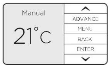
The controls are located on top of the heater consisting of a display screen and six touch sensitive buttons.
1 Display Screen
2 'Menu' Button
3 'Back' Button
4 'Up and Down' Arrows
5 'Enter' Button
6 'Advance' Button
7 Heating Status
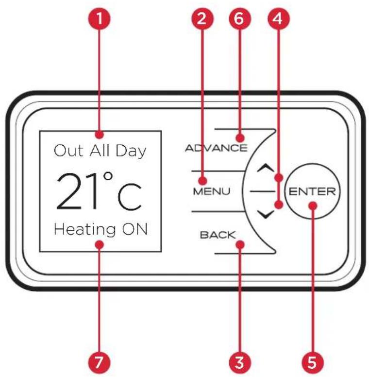
The heater is fitted with an adjustable thermostat enabling the room temperature to be controlled. The minimum room temperature is 7^ C. The maximum temperature is set to 26^ C by default. The minimum and maximum selectable temperatures available on the heater can be adjusted in the settings menu. A temperature of 21^ C is a common comfortable room temperature.

NOTE:
Your heater may produce some noise during operation. This noise is caused by the expansion and contraction of the element as it changes temperature, and is normal for this type of product. Whilst the noise produced is usually very quiet, certain environmental factors can make it more noticeable, such as hard flooring or minimal furnishings If you believe that the expansion noise is excessive, please contact us.

NOTE:
Should the heater fail to operate, this may be caused by the room temperature being higher than the thermostat setting.
The heater controls can be easily adjusted by using the six buttons on the User Interface.
- The Home Screen shows the options available at each stage of adjustment. Here the current target room temperature is displayed along with the mode of operation. Any use of the Advance function will be displayed here, and pressing Enter will show the functions which are enabled.
The currently active mode of operation is displayed at the top of the screen e.g. 'Manual' or 'Out All Day' timer.
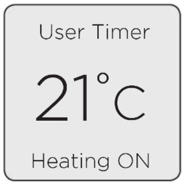
When the heater is in a timer profile and trying to achieve or maintain a room temperature, 'Heating On' will be displayed, otherwise, 'Heating Off' will be displayed. The words 'Heating On / Off' will not be displayed in a manual mode of operation.
When the controller buttons have not been pressed for a long period of time, the display will 'sleep' and the text will disappear. The heater is still on and active in whatever Mode it was set to.
-
Menu - Displays the Main Menu;
-
Boost - Activate Boost Mode
- Mode - Set the mode of operation.
-
Settings - Time/Date, Temperature units etc.
-
Back returns to the previous screen.
-
The Up and Down buttons are used to navigate through the menus and adjust the required room temperature on the main screen. The screen colour changes based on the temperature selected, showing deep blue through to bright red.
-
Enter is used to enter sub menus and to confirm actions.
-
The Advance button is only used when a Timer Mode is active, it allows the timer schedule to be changed temporarily by forcing a 'Heating On' period to begin or end early.
Timer Modes
Timer Modes offer the most efficient mode of operation for a predictable heat demand. Additional functions such as Advance and Boost allow the User to make temporary adjustments to timer schedules for a more flexible operation.
Each timer is broken down into 4 definable 'Heating On' time periods and temperatures per day, for each day of the week. Each day consists of a 24-Hour period, starting and finishing at midnight.
When the heater is in a timer profile and trying to achieve or maintain a room temperature, 'Heating On' will be displayed, otherwise, 'Heating Off' will be displayed.
It is possible to change the Target Temperature of a 'Heating On' period when that period is active. This will temporarily adjust the Target Temperature for just that instance and will not permanently modify the settings for the timer in use.
| User Timer21°CHeating ON | |
| ADVANCE | |
| MENU | |
| BACK | |
| ENTER | |

NOTE:
If Adaptive Start is enabled, the heater will maintain the room at the required temperature for the duration of the heating period. To achieve this, the heater will begin heating the room before the start of the heating period to ensure the room is at the required temperature when the period starts.
If Adaptive Start (AS) is disabled, the heater will not operate until the beginning of the heating period. This should be taken into consideration when setting the heating periods.
See page 23 for instruction on enabling/disabling Adaptive Start.
Available Timer Modes
To choose a timer mode, press Menu from the home screen. Use the Up / Down keys to highlight 'Mode', then press Enter to select. 'Timer Mode' should be highlighted. Press Enter to select.

flowchart
graph LR
    A["Manual 21°C"] --> B["Main Menu"]
    B --> C["Mode"]
    C --> D["Main Menu"]
    D --> E["Mode"]
    E --> F["Main Menu"]
    style A fill:#f9f,stroke:#333
    style B fill:#ccf,stroke:#333
    style C fill:#cfc,stroke:#333
    style D fill:#fcc,stroke:#333
    style E fill:#cff,stroke:#333
    style F fill:#ffc,stroke:#333
A list of Timer Modes will be shown. Their default settings are shown in the table below.
| Period 1 Period 2 Period 3 Period 4 | |||||||
| User Timer 06:30 - 09:30 21 | °C 11:00 - 13:00 21 | °C 15:00 - 17:00 21 | °C 18:00 - 22:00 21 | °C | |||
| Home All Day 07:00 - 08:30 21 | °C 17:30 - 22:00 21 | °C 00:00 - 00:00 | 00:00 - 00:00 | ||||
| Out All Day | 08:00 - 21:00 | 21 °C 17:30 - 22:00 | 00:00 - 00:00 | 00:00 - 00:00 | |||
| Away Mode | Away Mode does not operate in the same way as the other Timers.See section 'Away Mode' on page 16 | ||||||
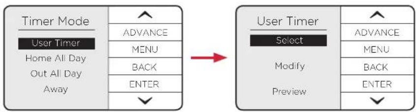
Highlight one of the available Timer Modes using the Up / Down keys. Press Enter to select.
flowchart
graph LR
    A["User Timer\nHome All Day\nOut All Day\nAway"] --> B["User Timer\nSelect"]
    B --> C["Select"]
    C --> D["Advance"]
    C --> E["MENU"]
    C --> F["BACK"]
    C --> G["ENTER"]
    A --> H["User Timer\nPreview"]
    H --> I["User Timer\nMenu"]
    H --> J["Advance"]
    H --> K["MENU"]
    H --> L["BACK"]
    H --> M["ENTER"]
For User Timer, Home All Day and Out All Day, three choices will be available:
Select - This option will activate the timer
Modify - This option allows the timer's Heating On times and Target Temperatures to be modified
Preview - This option displays the timer's configuration. This is handy to quickly check the timer without being able to change any values
Modifying a Timer Mode
Each timer is broken down into 4 definable 'Heating On' periods and temperatures per day.
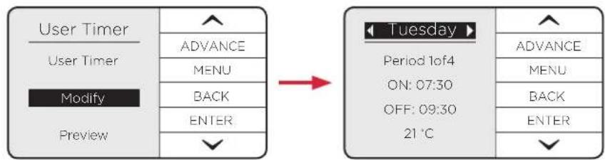
When Modify is chosen, 'Heating On' period 1 of 4 for the current day is displayed. The current day will be highlighted.

NOTE:
Once modified a Timer Mode must be selected if you want to begin using it.
flowchart
graph LR
    A["User Timer"] --> B["ADVANCE"]
    B --> C["MENU"]
    C --> D["BACK"]
    D --> E["ENTER"]
    F["Modify"] --> G["Preview"]
    H["Tuesday"] --> I["Period 1of4"]
    I --> J["ON: 07:30"]
    J --> K["OFF: 09:30"]
    K --> L["21 °C"]
    M["ADVICE"] --> N["MENU"]
    N --> O["BACK"]
    O --> P["ENTER"]
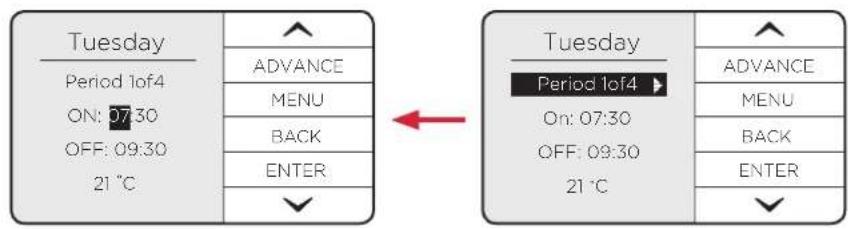
Select and change each option using the Up, Down and Enter buttons.
Copy & Paste
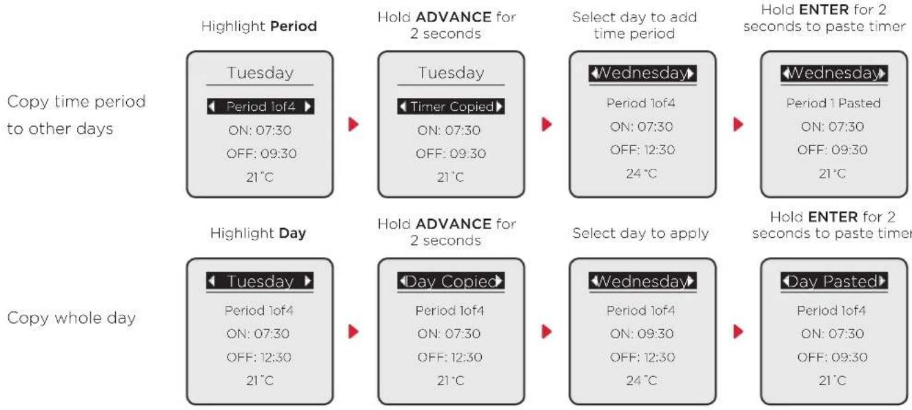
To save time when modifying a Timer Mode, the Advance button can be used to copy and paste settings. Individual heating periods from one day or every heating period from a day can be copied to another day.
flowchart
graph LR
    A["Highlight Period"] --> B["Tuesday"]
    B --> C["Period 1of4 ON: 07:30 OFF: 09:30 21℃"]
    C --> D["Hold ADVANCE for 2 seconds"]
    D --> E["Tuesday"]
    E --> F["Timer Copied ON: 07:30 OFF: 09:30 21℃"]
    F --> G["Select day to add time period"]
    G --> H["Wednesday"]
    H --> I["Period 1 of4 ON: 07:30 OFF: 12:30 24℃"]
    I --> J["Hold ENTER for 2 seconds to paste timer"]
    J --> K["Wednesday"]
    K --> L["Period 1 Pasted ON: 07:30 OFF: 09:30 21℃"]
    L --> M["Hold ENTER for 2 seconds to past timer"]

    N["Copy whole day"] --> O["Tuesday"]
    O --> P["Period 1of4 ON: 07:30 OFF: 12:30 21℃"]
    P --> Q["Hold ADVANCE for 2 seconds"]
    Q --> R["Day Copied ON: 07:30 OFF: 12:30 21℃"]
    R --> S["Select day to apply"]
    S --> T["Wednesday"]
    T --> U["Period 1 of4 ON: 09:30 OFF: 12:30 24℃"]
    U --> V["Hold ENTER for 2 seconds to past timer"]
    V --> W["Day Pasted ON: 07:30 OFF: 09:30 21℃"]
The ‘Advance’ Function
The Advance button is only used when a Timer Mode is active and allows the timer schedule to be changed temporarily. This button allows a 'Heating On' period to begin or end early.
This is useful if you are at home when you had not planned to be, or need to leave when you had planned to have the heating on.
If the heater displays 'Heating Off' and heat is required, press the Advance button. If the heater is in 'Heating On' and heat is not required, press the Advance button and the heater and the heater will stop heating until the beginning of the next 'Heating On' period.
| Pre-action State Action Impact | ||
| Heating On (Timer Mode) | Advance activated | Heating On period switched to Heating Off until the next scheduled 'Comfort On' period. |
| Heating Off (Timer Mode) | Advance activated | Heating Off switched to Heating On until the next scheduled 'Heating Off' period. |
| Heating On (Advance Active) | Advance deactivated | Heating On switches to Heating Off. Appliance in following schedule set in the currently active Timer Profile |
| Heating Off (Advance Active) | Advance deactivated | Heating Off Switches to Heating On. Appliance in following schedule set in the currently active Timer Profile |
Away Mode
Away Mode temporarily overrides the active mode before returning the Heater back to the previously active mode.
This is handy if you are temporarily away at the shops or on holiday and want your heating to resume as normal operation automatically when you return.
While active, Away Mode can maintain a minimum room temperature. By default, this is set to 7 °C (frost protection temperature). This can be modified when Away Mode is activated. The heater will also remember the last Away Mode Target Temperature defined while Away Mode is active.
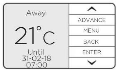
The Away countdown is set in Hours, a Date and a Target Temperature.
The starting Hours and Date show '00 hours' and the current date. Date and Hours are set separately on the heater, making the feature useful for popping out to the shops or going away on holiday.
- The date set is the return date; therefore, Away Mode will end at 23:59 of the day before. E.g. if a return date of 02.02.2018 is set, Away Mode will end at 23:59 on 01.02.2018.
- If hours are set, this will extend Away Mode end from 23:59 on the day before the date set.
- If only hours and no date is set, Away Mode will count from either the current time, or if a date is set.

flowchart
graph LR
    A["Timer Mode\nUser Timer\nHome All Day\nOut All Day\nAway"] --> B["Return Date/Time\nSaturday 31-2-18\n07:00\n21°C"]
    B --> C["Return Date/Time\n✓\nAway Set"]
    style A fill:#f9f,stroke:#333
    style B fill:#f9f,stroke:#333
    style C fill:#f9f,stroke:#333

NOTE:
The Back button can be used to end the Away Mode countdown early.
Continuous Heat Modes
A continuous heat mode is effectively a constant 'Heating On' period. The Heater will remain in a continuous heat mode indefinitely until the mode is changed by the User.
Available Continuous Heat Modes
Each continuous heat mode starts with a default Target Temperature value.
- Manual
- Default 21^ C
- Can be changed from the Home Screen to any value within the Heater's Temperature Range.
• Eco
- Default 19^ C
- Can be changed from the Home Screen to any value in the Heater's minimum temperature range (8-18°C)
- Frost Protection
- Default 7^ C
- Not User Definable

flowchart
graph LR
    A["User Timer\n21°C\nHeating ON"] --> B["Main Menu\nBoost\nModes\nSettings"]
    B --> C["Modes\nTimer Mode\nManual Mode\nEco Mode\nFrost Protect"]
To select a continuous heat mode, first press the Menu button. Use the arrow keys to highlight 'Modes' and press the Enter button. From here, use the arrow keys to highlight the desired continuous heat mode and press Enter to select. You will then be returned to the home screen in your chosen mode.
Boost Mode
Boost can be activated at any time, when the product is set to any Timer or Continuous heat mode; even if Advance is active, this mode will provide a temporary 'Boost' of heat. For settings, see Boost settings on Page 22.
Boost Mode can be activated from the Home Screen by pressing Menu to access the Main Menu, then pressing Enter to select 'Boost'. 'Boost' will always be listed as the top item on the list.

flowchart
graph LR
    A["Main Menu\nBoost\nModes\nSettings"] --> B["Main Menu\nBoost Temp\n25 °C\nBoost Time\n0 Mins"]
    B --> C["Boost\nBoost Temp\n25 °C\nBoost Time\n30 Mins"]
    style A fill:#f9f,stroke:#333
    style B fill:#ccf,stroke:#333
    style C fill:#cfc,stroke:#333
Activating Boost will present two selectable options: Boost Temp (Boost Target Temperature) and Boost Time (Boost Duration Countdown). The default values for these can be set in the Settings Menu.
The Up, Down and Enter buttons can be used to modify these values. Pressing Back will end Boost early, restoring the heater back to its previously active mode.
- The Boost Temp can be set to any value within the Heater's Target Temperature Range setting.
- The Boost Time can be increased in the following increments: 30 mins, 1 hour, 2 hours, 3 hours, 4 hours.
These increments can be restricted with the Max. Boost Duration Range setting. To modify this range, see Boost Settings on Page 22.
Once the Boost Duration Countdown has reached 0, the Heater will return to the mode that was active before Boost was activated.
Product Locks
Product Locks are methods of locking the heater's controller to restrict access to functions. This can be activated and configured via the Settings Menu. When Product Lock is activated, the heater continues to run in whichever mode is currently active and any/all wireless communications remain active if enabled.
Child Lock
This is the simplest locking method and does not utilise a PIN code. It is toggled on/off on the heater's controller by pressing and holding the Back and Enter buttons for three seconds.
While Child Lock is active, the heater will continue to operate in whatever mode, with whatever settings it had before the lock was activated.
There are no exception rules with this lock, and the user can only choose to unlock the heater if they wish to change the temperature, modes or settings.
Heater Lock (PIN Lock)
Heater Lock is the most customisable and secure lock on the heater. This allows the heater to be configured in any way, then locked into those settings and modes.
When PIN Lock is activated, pressing the Menu button will show one item* that can be selected - 'Unlock'. Selecting 'Unlock' prompts the User to complete the applicable Unlock action:
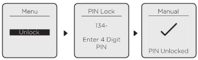
flowchart
graph LR
    A["Menu\nUnlock"] --> B["PIN Lock\n134-\nEnter 4 Digit\nPIN"]
    B --> C["Manual\n✓\nPIN Unlocked"]
*Unless Boost Mode has been enabled during UI Lock
PIN Lock Exceptions
It is possible to allow the 'Advance' and 'Boost' functions to be enabled/disabled when PIN Lock is active.
There are up to 4 exceptions. These exceptions include:
- Advance
- Ability to activate using the Advance button.
- Boost
- Ability to activate using the 'hotkey' listed in the Main Menu
- Ability to modify the Boost Temperature
- Ability to modify the Boost Duration
'Advance Function' Operation during PIN Lock
If Advance has been enabled during PIN Lock, the Advance button will remain active when PIN Lock is active. This will function in the same way it would if the controls were not locked: only if the Heater is Locked into a Timer Mode.
- If Advance is enabled during UI lock, the Advance button will function as normal while the Heater is set to a Timer Mode.
- If Advance is Disabled during UI lock, the Advance button will not function.
'Boost Function' Operation during PIN Lock
If enabled, Boost will function in the same way as it does when PIN Lock is not active unless modification of Boost Temperature and Boost Duration have been disabled.
Boost Temperature and Boost Duration will be set to the default values when 'Boost' is activated. If either of these values have been disabled during Product lock, when the user tries to modify them the heater's display will show the message 'Disabled' and only the default value can be used. The default values can be changed outside of PIN Lock.
Settings
To navigate to the Settings Menu, from the Home Screen:
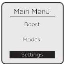
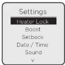
Press the Menu button to access the Main Menu. Use the Up / Down buttons to highlight 'Settings', then press the Enter button. Each of the following headings relate to an item in the settings menu.
Heater Lock
Set Lock
Heater (PIN) Lock can be enabled here by highlighting 'Heater Lock' and pressing Enter to enter the Heater Lock menu. Highlight 'Set Lock', press Enter, enter a 4-digit PIN code, then press Enter to lock the heater.
Lock Settings
Before PIN Lock is enabled, the User can select 'Lock Settings' to enable/disable the Advance and/or Boost functions, as well as enable/disable modification of the Boost Temperature and Boost Duration. See below.
Boost Lock
Three settings can be modified within this Menu:
-
Enable / Disable - The 'Boost' Menu Item can be Enabled/Disabled while PIN Lock is active.
• Temperature Rule - Modifiable Boost Temperature while PIN Lock is active -
Enable - While Boost is active, the User can modify this value as they normally would
- Disable - Default value will be loaded. When the user tries to modify the value, the UI will show the following text: 'Disabled'.
• Duration Rule - Modifiable Boost Duration while PIN Lock is active.
- Enable - While Boost is active, the User can modify this value as they normally would
- Disable - Default value will be loaded. When the user tries to modify the value, the UI will show the following text: 'Disabled'
Advance Lock
- Enable / Disable - This setting allows the User to Enable or Disable the Advance button while UI Lock is active.
Boost Settings
Default Boost Target Temperature
This is the default Boost Target Temperature that is used when 'Boost Mode' is activated.
Defined as a temperature value, this must be within the Heater's Target Temperature Range.
If the Target Temperature Range settings are changed then the Default Boost Temperature Range will be automatically changed to the closest valid temperature within Target Temperature Range.
Max. Boost Duration
This is the maximum length of time that the user is able to activate 'Boost' for.
Shown in minutes (when under an hour) or hours (if over an hour) in the following increments: 30 mins, 1 hour, 2 hours, 3 hours, 4 hours.
The value chosen will be the max allowed when boost is activated.
Setback Settings
Setback is a function that only modifies Timer Mode operation. When Setback is enabled it overrides any Heating Off period to maintain a constant temperature.
This can be used to prevent the room temperature from falling below a minimum value while there is no demand for heat (Heating Off).
The value of this temperature is restricted to a value between 7 and 18 °C. This is because Setback should not be treated as a regular Heating On period.
Date & Time Settings
This allows the Time, Date and Daylight Savings Time settings to be modified.
Sound Settings
Audio feedback when the user presses a button can be enabled or disabled here.
'Comms' (Communications) Settings
This allows Wireless Connectivity features to be enabled or disabled. Entering this menu item will display a list of available communications methods to that heater.
Adaptive Settings
Open Window Detection
This is a global setting that can interrupt any active mode. Activating this setting enables Open Window Detection to switch the Heater to a 'Heating Off' state if it detects an open window in the room it's operating in.
Adaptive Start
Adaptive Start is predictive function that only modifies Timer Mode operation. This function models the heating characteristics of the room and uses that information to pre-heat the room for only the time required to achieve the Target Temperature by the start of the 'Heating On' period.
For example, with Adaptive Start off, the 'Heating On' time is the time that the Heater will begin to try and achieve the Target Temperature. With Adaptive Start On, the Heater will begin to heat the room before the User-defined Heating On time so that the Target Temperature is achieved when the User defined the 'Heating On' start time.

NOTE: Adaptive Start
This is a continuously learning function and will be affected daily by changes in the heater's environment. The heater will take into account the starting temperature of the room so pre-heating should remain accurate.
It is important that if multiple heaters are installed in one room that all heaters have the Adaptive Start (AS) function enabled. If this is not the case, heaters with AS enabled will pre-heat the room to the desired target temperature before the heaters with AS disabled attempt to output heat.
It is likely that if two heaters are required in one room, that the output from one heater may not be sufficient to heat the room alone. This may cause the pre-heat time calculation to extend to a large degree if the heaters do not all have AS enabled. This may lead to heat at unwanted times and excessive wear to some heaters.
A two-hour limit is enforced on the calculation, however, if all heaters have AS enabled and pre-heating takes over one-hour, extreme environmental factors may be affecting the calculation or the heaters may be under sized for the room. Please contact us for support if your pre-heat time seems excessive.

NOTE: Open Window Detection
In environments where the product may read sudden decreases in temperature, this feature may activate in error. This can occur in drafty or poorly insulated environments as well as if the heater is undersized for the room. This feature should be disabled using the instructions above if activating for reasons other than the intended purpose. If you think that your environment is not as described here and this feature is activating, please contact our customer care team with the details on the rear page of this document.
Advanced Settings
These settings can be used to significantly change the operation of the heater. While useful for very specific requirements, there is a much higher risk of User error and unintended consequences of changing these settings compared to the top-level settings menu. It is recommended that these settings are only modified by trained professionals.
To navigate to the Advanced settings menu, from the home screen:
Press and hold Advance and Menu buttons for 5 seconds.
Each of the following headings relate to an item in the settings menu.
Temperature Settings
Temp Units (Temperature Units)
This setting defines which temperature units are displayed on the heater. The default is ^ , but ^ can be set. When ^ is selected, the heater will covert ^ values to ^ and round to the nearest number.
Service Settings
Room Temp (Temperature) Offset
- Panels and Storage Heaters
• Service personnel use only. - Allows the manual adjustment of electronic thermostat reading by +/-0.2^
Factory Reset
This setting allows the User to restore the default values to all settings. Returning the product to the same state that it left the factory.
Error Codes
Error codes are to be defined as a list. Each error code must be defined as a parameter that Central Control can read.
| Fault Code Description | |
| 20 | Component thermistor hardware fault |
| 21 | |
| 22 | |
| 23 | |
| 24 | |
| 30 | Component overheat |
| 32 | |
| 33 | |
| 34 | |
| 40 Internal serial comms error | |
| 41 Heating element fault | |
| 50 Open window detected | |
| 51 Low water | |
| 52 Heat output disabled | |
| 53 Time loss error | |
| 54 Occupancy sensor not detected | |
| 55 Unknown error | |
| 60 Wireless communication module error | |
| 61 Hub connection error | |
Maintenance
IMPORTANT:
Before replacing the battery ensure the heater is isolated from the electricity supply.

NOTE:
Battery should be disposed of in an appropriate manner
This product is fitted with a replaceable battery in the controls. To replace the battery, follow the steps below.
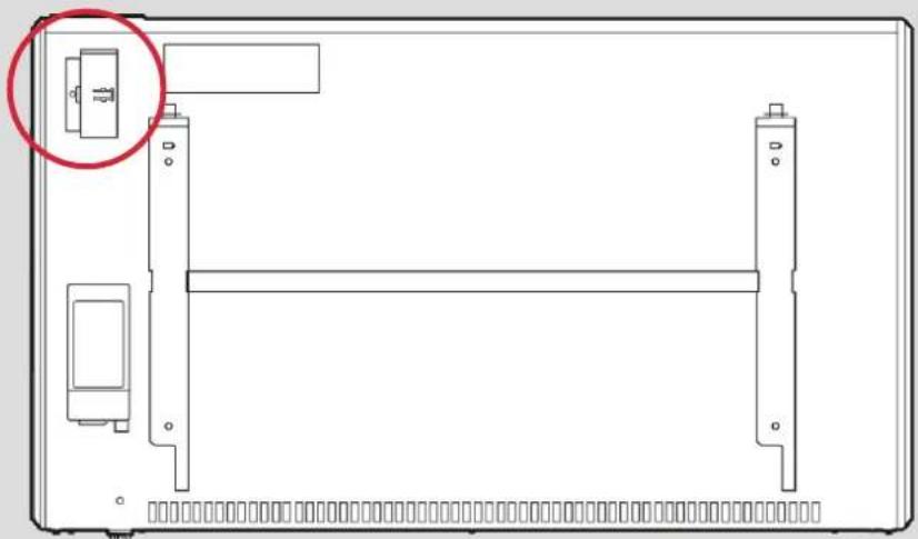
- Isolate the power supply to the product, then unhinge the heater from the wall using the clips shown in Fig. 2 (page 7) and locate the battery module, indicated in Fig. 5.
2/3. Slide the catch and pull module from the controls. - Remove the coin cell battery and replace.
- Slide module back in place, ensuring clip is engaged.
Fig. 5
1.
natural_image
Technical line drawing of a mechanical assembly with no visible text or symbols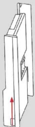
natural_image
Technical line drawing of a mechanical component with a red arrow indicating upward motion (no text or symbols)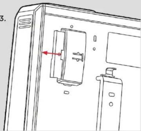
natural_image
Technical line drawing of a door panel with an open door and handle, showing internal components (no text or symbols)RF Module Installation
- Unhinge the heater from the wall using the clips shown in Fig. 2 (page 7) and locate the battery module, indicated in Fig. 5; 1.
- Slide the catch and pull module from the controls (See Fig 5; 2/3).
- Replace the tray with the radio frequency module
- Power the product on and make sure that the RF comms are enabled. Comms settings will be located in the settings menu (see page 22)
Important
During the initial operation, some odour may be noticed due to the newness of materials used in manufacture. This is normal and will disappear after a short period of use. It is however advisable to keep the room well ventilated
Cleaning
WARNING - ALWAYS DISCONNECT FROM THE POWER SUPPLY BEFORE CLEANING THE HEATER.
Before commencing cleaning, isolate the heater from the electrical supply and allow it to cool. The outside can be cleaned by wiping it over with a soft dry cloth. Do not use abrasive cleaning powders or furniture polish, as this can damage the surface finish. To release the heater from the wall bracket for cleaning or redecoration, depress the latch on both brackets (See Fig. 2) and hinge forward.
Guarantee
What does a Dimplex Guarantee cover?
Dimplex products deliver reliable service for normal use in dwellings. All Dimplex products are individually tested before leaving the factory.
If you are a consumer and you experience a problem with your Dimplex product, which is found to be defective due to faulty materials or workmanship within the Warranty Period, this Dimplex Guarantee will cover repair or - at the discretion of Dimplex - replacement with a functionally equivalent Dimplex product.
The Dimplex Guarantee Period is two calendar years from the date of purchase of your Dimplex product, or the date of delivery of the product, if later. The Dimplex Guarantee is conditional upon you providing the original purchase receipt as proof of purchase. Please therefore retain your receipt as proof of purchase.
If you do experience a problem with your Dimplex product please call the Helpline on +44 [0]344 879 3588 or visit https://www.dimplex.co.uk/support. For ROI please email serviceireland@glendimplex.com or call +353(0)1
842 833. We will need details of your Dimplex product, its serial number and a description of the fault which has occurred. You can find the model number and serial number for your Dimplex product on the heaters side. Once we receive your information and proof of purchase we will contact you to make the necessary arrangements.
If your Dimplex product is not covered by this Dimplex Guarantee there may be a charge to repair your product. However, we will contact you for agreement to any charges before any chargeable service is carried out.
What is not covered by a Dimplex Guarantee?
The Dimplex Guarantee does not cover any of the following:
- Any fault or damage to your Dimplex product due to faulty materials or workmanship occurring outside the two-year Guarantee Period.
- Any fault or damage occurring to any pre-owned Dimplex product or to any other equipment or property.
- Accidental damage to your Dimplex product or damage to your Dimplex product from external sources (for example, transit, weather, electrical outages or power surges).
- Fault or damage to your Dimplex product which is:
- Not due to faulty materials or workmanship or which is due to circumstances outside Dimplex's control.
- Caused by use of your Dimplex product for anything other than normal dwelling purposes in the country where it was purchased.
- Caused by any misuse, abuse or negligent use of the Dimplex product, including but not limited to any failure to use it in accordance with the Operating Instructions supplied with the product.
- Caused by any failure to assemble, install clean and maintain your Dimplex product in accordance with the Operating Instructions supplied with the product unless this was carried out by Dimplex or its authorised dealers.
- Caused by repairs or alterations to your Dimplex product not carried out by Dimplex service personnel or its authorised dealer(s).
- Caused by use of any consumables or spare parts for your Dimplex product which are not Dimplex -specified.
Terms and Conditions
- The Dimplex Guarantee is valid for Dimplex from the date of purchase of your Dimplex product from a recognised retailer in the country of purchase and use, or the date of delivery of the product if later, always provided the original receipt has been retained and is produced as proof of purchase.
- You must provide to Dimplex or its authorised agents on request the original receipt as proof of purchase and - if required by Dimplex - proof of delivery. If you are unable to provide this documentation, you will be required to pay for any repair work required.
- Any repair work under the Dimplex Guarantee will be carried out by Dimplex or its authorised dealer(s) and any parts that are replaced will become the property of Dimplex. Any repairs performed under the Dimplex Guarantee will not extend the Guarantee Period.
- Any replacement of your Dimplex product by Dimplex during the Guarantee Period will start the two-year Guarantee Period afresh from the date of delivery of the replacement Dimplex product to you.
- The Dimplex Guarantee does not entitle you to recovery of any indirect or consequential loss or damage including but not limited to loss or damage to any other property.
- The Dimplex Guarantee is in addition to your statutory rights as a consumer and your statutory rights are not affected by this Dimplex Guarantee.
Contact Dimplex
If you have any questions about what the Dimplex Guarantee covers and does not cover or how to claim under the Dimplex Guarantee, please contact us using the information on the back page.
Contact details
Millbrook House, Grange Drive, Hedge End, Southampton, SO30 2DF

natural_image
Symbol of a trash bin crossed with a diagonal line, no text or numbers presentImportant
For electrical products sold within the European Community. At the end of the electrical products useful life it should not be disposed of with household waste. Please recycle where facilities exist. Check with a Local Authority or retailer for recycling advice in your country. Batteries should be disposed of or recycled in accordance with WEEE Directive 2012/19/EU. Packaging should be recycled where possible.
DCDimplex®
Customer Helpline: 0344 879 3588
aftersales@dimplex.co.uk
www.dimplex.co.uk
Glen Dimplex Heating & Ventilation
Millbrook House, Grange Drive, Hedge End, Southampton, SO30 2DF
- Q-Rad Electric Radiator
- CAUTION
- FAILURE TO FOLLOW THESE INSTRUCTIONS MAY CAUSE INJURY AND/OR DAMAGE AND MAY INVALIDATE YOUR GUARANTEE
- IMPORTANT SAFETY ADVICE
- OVERHEATING WARNING
- WARNING - THE SURFACES ON THIS HEATER CAN BE HOT.
- CAUTION - Some parts of this product can become very hot and cause burns. Particular attention has to be given where children and vulnerable people are present.
- SUITABLE APPLICATIONS
- SERVICING AND REPAIRS
- OPERATING WARNINGS
- ELECTRICAL INSTALLATION
- GREEN AND YELLOW: EARTH
- BLUE: NEUTRAL
- BROWN: LIVE
- CHILD SAFETY
- WARNING - KEEP BATTERIES OUT OF REACH OF CHILDREN
- WARNING: EARTHING
- WARNING: HAZARDOUS VOLTAGE
- WARNING: ACCESS TO LIVE PARTS
- Energy Related Product Directive
- Contact details
- Technical Details
- General
- Wall Mounting
- To mount the heater to the wall:
- WARNING:
- First Time Power-On
- Important
- DCimplex·Control
- Operation
- NOTE:
- Timer Modes
- Available Timer Modes
- Modifying a Timer Mode
- Copy & Paste
- The ‘Advance’ Function
- Away Mode
- Continuous Heat Modes
- Available Continuous Heat Modes
- - Manual
- • Eco
- - Frost Protection
- Boost Mode
- Product Locks
- Child Lock
- Heater Lock (PIN Lock)
- PIN Lock Exceptions
- - Advance
- - Boost
- 'Advance Function' Operation during PIN Lock
- 'Boost Function' Operation during PIN Lock
- Settings
- Heater Lock
- Set Lock
- Lock Settings
- Boost Lock
- Advance Lock
- Boost Settings
- Default Boost Target Temperature
- Max. Boost Duration
- Setback Settings
- Date & Time Settings
- Sound Settings
- 'Comms' (Communications) Settings
- Adaptive Settings
- Open Window Detection
- Adaptive Start
- NOTE: Adaptive Start
- NOTE: Open Window Detection
- Advanced Settings
- Temperature Settings
- Service Settings
- Factory Reset
- Error Codes
- Maintenance
- IMPORTANT:
- RF Module Installation
- Cleaning
- WARNING - ALWAYS DISCONNECT FROM THE POWER SUPPLY BEFORE CLEANING THE HEATER.
- Guarantee
- What does a Dimplex Guarantee cover?
- What is not covered by a Dimplex Guarantee?
- Terms and Conditions
- Contact Dimplex
Brand : DIMPLEX
Model : QRAD200E
Category : Radiator