
RF24T - Temperature regulator DIMPLEX - Free user manual and instructions
Find the device manual for free RF24T DIMPLEX in PDF.


| Product Type | Temperature Regulator (Thermostat) |
| Brand | Dimplex |
| Model | RF24T |
| Dimensions | 80 x 80 x 25 mm (approx.) |
| Weight | 120 g (approx.) |
| Power Supply | 2x AAA batteries (alkaline recommended) |
| Operating Temperature Range | 0°C to 40°C |
| Temperature Accuracy | +/- 0.5°C |
| Display | LCD screen with backlight |
| Main Functions | Room temperature control, programmable schedule, frost protection, manual override |
| Installation | Wall-mounted with screws and wall plugs (included) |
| Wireless Connectivity | RF signal to compatible receiver (e.g., Dimplex heating systems) |
| Maintenance | Clean with a soft, dry cloth. Do not use liquids or solvents. |
| Safety Features | Overheat protection, low battery indicator, child lock |
| Battery Replacement | Replace when low battery icon appears on display |
| Repairability | User-replaceable batteries only. No other user-serviceable parts. |
| Spare Parts | Batteries (standard AAA), optional wall plate (contact Dimplex) |
Frequently Asked Questions - RF24T DIMPLEX
User questions about RF24T DIMPLEX
0 question about this device. Answer the ones you know or ask your own.
Ask a new question about this device
Download the instructions for your Temperature regulator in PDF format for free! Find your manual RF24T - DIMPLEX and take your electronic device back in hand. On this page are published all the documents necessary for the use of your device. RF24T by DIMPLEX.
USER MANUAL RF24T DIMPLEX
Please note that some of the contact details on this PDF document may not be current.
Please use the following details if you need to contact us:
Telephone: 0844 879 3588 Email: customer.services@gdcgroup.co.uk
The customer support section of our website also features a wide range of information which may be of use to you and is available 24 hours a day. It includes:
- Operating and installation instructions
- Easy 'How to use' guides for storage heaters
• Service and repairs
• Where to buy our products
• Literature downloads
• Heating requirement calculator
Visit - www.dimplex.co.uk/support
RF Controller Unit: 24hr Controller & Receiver
CE
RF24234P01 Issue 2
IMPORTANT : THESE INSTRUCTIONS SHOULD BE READ CAREFULLY AND RETAINED FOR FUTURE REFERENCE
Important Safety Advice
When using electrical appliances, basic precautions should always be followed to reduce the risk of fire, electrical shock, and injury to persons, including the following:
This product is splash proof to IP24 standard and may be used in bathrooms in Zones 2 & 3 only, however not in the immediate vicinity of baths, showers, water connections, wash basins or swimming pools.
This unit must only be used on an A.C Mains supply of 230/240V with products up to a maximum of 2kW.
Ensure that supply cables to the product are of adequate current carrying capacity.
This product is used to control separate heating appliances. Please note the safety guidelines of the controlled product must be adhered to at all times.
General
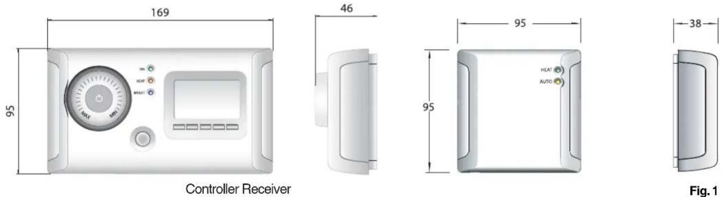
The RF Controller Unit is an electronic device which provides wireless room temperature control for use with heating appliances. The Unit can be used to control multiple heating appliances. Note: Each appliance requires a Receiver Unit.
The Unit can be used in conjunction with heating appliances with a maximum heating capacity of 2kW. The Controller Unit cannot be used with a Quartz Halogen heater without a suitable in-line contactor.
The RF Controller Unit consists of a Controller and a Receiver. Both the Controller and Receiver are wall mounted. The Controller provides wireless room temperature control. Control of the product is achieved via an RF signal from the Controller to Receiver which is wired direct to the heating appliance. This eases installation. To quickly heat a cold room the Controller incorporates a 'Boost' function which overrides the thermostatic control for a set period of time.
Installation
Before undertaking installation work, ensure the electricity supply is disconnected from any relevant fixed wiring.
- All wiring should be carried out by a qualified electrician in accordance with the current IEE wiring regulations.
- Both the Controller and Receiver units are designed to be fitted to a standard single BS backing box with a depth of at least 25mm. The backing box (not supplied) should already be recessed into the wall. Alternatively a surface mounted wall box may be used.
- Ensure the top and bottom lugs (if fitted) of metal backing boxes are removed prior to installation.
- The location of the Controller is important. The Controller is fitted with a room temperature sensing device and therefore will not function correctly if positioned too close to a heat source or draught area. Please ensure the Controller is not located above or within 500mm of a heat source or draught.
Controller
a) Remove screw 'x' from the underside of the Controller unit - see Fig. 2.
b) The front facia is held in place by clips at the top. It must be removed by lifting the top of the facia upwards and then outwards - see Fig. 2.
c) Connect the fixed wiring of the premises from the back box to the clearly marked terminals on the Controller - see Fig. 3.
d) Set the thermostat knob to 'MIN' position (fully counter clockwise) to allow access to the screw hole.
e) Secure the Controller to the backing box using the screws provided (located on rear moulding) - see Fig. 2.
Note: The Controller front facia should not be refitted until the unit has been programmed - see 'Unit Set-Up'.
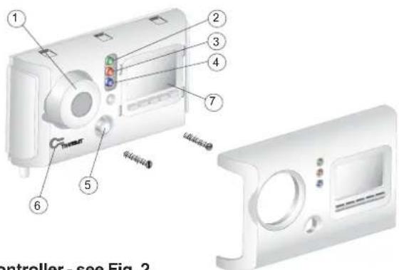
Fig. 2
Controller - see Fig. 2
- Standby button/thermostat control knob
- 'ON' Indicator
- 'HEAT' Indicator
- 'BOOST' Indicator
- 'BOOST' button
- 'TRANSMIT' button
- Timer unit & controls
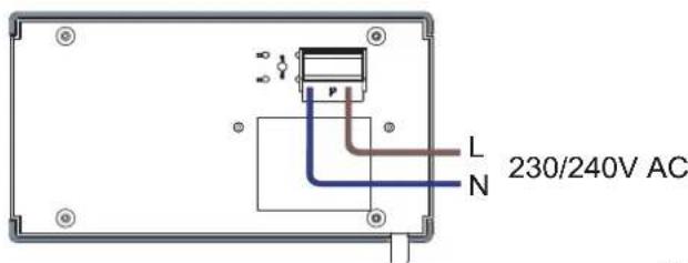
Fig. 3
Controller Wiring - see Fig. 3
Receiver
a) If the heating appliance to be used in conjunction with the Controller is fitted with a plug, please remove the plug and strip the wires to the appropriate length.
b) Remove the front facia of the Receiver - see steps 'a' and 'b' in 'Controller'. The cable clamp on the rear of the Receiver should then be removed.
c) The cable of the heating appliance is fed through an opening on the underside of the Receiver unit - see Fig. 5.
d) The cable from the heating appliance is then wired to the terminal block labelled (out). Please ensure the wires are connected in accordance with the marked terminals - see Fig. 5.
e) The cable from the heating appliance is then clamped to the rear of the Receiver unit using the cable clamp previously removed.
f) Connect the fixed wiring of the premises (via a local isolation switch or RCB) from the backing box to the clearly marked terminals on the Receiver unit (see Fig. 5). Please ensure that the unit is earthed to the backing box.
g) Secure the Receiver to the back box using the screws provided (located on rear moulding) - see Fig. 4.
Note: The Receiver front facia should not be refitted until the unit has been set up (see 'Unit Set-Up').
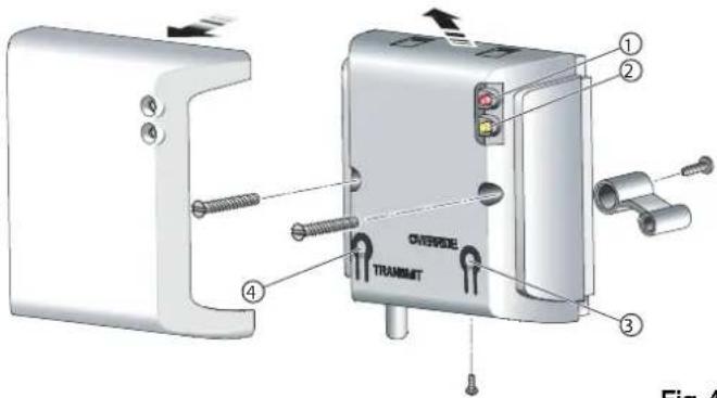
Fig. 4
Receiver - see Fig. 4
- 'HEAT' Indicator
- 'AUTO' Indicator
- 'OVERRIDE' button
- 'TRANSMIT' button
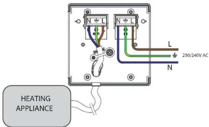
Fig. 5
Receiver Wiring - see Fig. 5
Unit Set-Up
The Receiver must be synchronised to suit your individual Controller. Each Controller can be used to control multiple heating appliances.
- Remove the front facias from both the Controller and Receiver units (see 'Installation').
- Ensure both the Controller and Receiver(s) are powered up. To activate the Controller press the standby button see '1' in Fig. 2. When activated, the 'ON' (Green) light will illuminate.
- Press the 'TRANSMIT' button on the Receiver. The Receiver goes into synchronise mode. This is indicated by both the 'AUTO' (yellow) and the 'HEAT' (Red) lights flashing. If more than one Receiver is to be controlled by a single Controller all Receivers must similarly be put into synchronise mode. Each Receiver will remain in synchronise mode for approximately one minute.
- With the Receiver(s) in the synchronise mode the 'TRANSMIT' button on the Controller is then pressed. This puts the Controller in synchronise mode, this is indicated by the Controller 'HEAT' (red) and 'BOOST' (blue) lights flashing. The Controller will remain in synchronise mode for approximately ten seconds.
- The Receiver will automatically go into auto mode once a signal has been received from the Controller. The Controller is ready once the 'AUTO' (yellow) light is lit on the Receiver.
- The front facias should then be replaced on both the Controller and Receiver, ensuring the bottom screw is replaced.
Operating Instructions
The Unit controls the room temperature by interrupting the power supply to the appliance, therefore ensure that the appliance is always switched on and its thermostat (if any) is always set to its maximum position. If the Controller is in standby mode all three lights will be off.
Timer Mode Selection
There are three different operating modes. Press MODE to cycle through these:
MAN OFF - heating is permanently Off - see Fig. 1.
This is also the default screen.
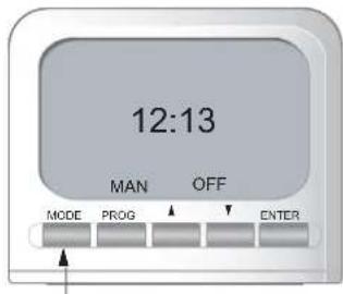
Fig. 6
MAN ON - this mode overrides the timer and the heat may be permanently ON. The heater may be controlled manually. See 'Manual Control' - see Fig. 7.
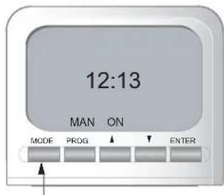
Fig. 7
AUTO - runs the programmed times - see Fig. 8.
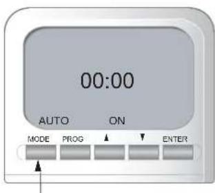
Fig. 8
Set Time
Press the PROG key once to set time. The ⑨ appears on the screen (see Fig. 9) and the hours can be set using the ▲▼ keys. Press ENTER when finished setting the hours. Set minutes using the ▲▼ keys and press ENTER.
Time is now set.
Set Program
A maximum of four program periods can be set as follows;
Press PROG twice (see Fig. 10). The program settings can now be entered (starting with P1 ON, where P1 ON is the first ON time setting).
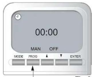
Fig. 9
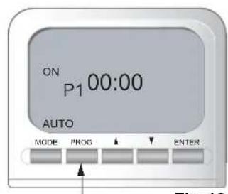
Fig. 10
a) set P1 ON time:
Set the hours using ▲▼ and press ENTER. Then set the minutes using ▲▼ and press ENTER.
NOTE: Time is set in 10 minute blocks.
Then set P1 OFF time:
Set the hours using ▲▼ and press ENTER.
Then set the minutes using ▲▼ and press ENTER. If only one program is required, press PROG now to return to default display OR
b) set P2 ON and OFF times: repeat procedure as 'a)' above.
c) set P3 ON and OFF times: repeat procedure as 'a)' above.
d) set P4 ON and OFF times: repeat procedure as 'a)' above.
After programming P4 the default screen is automatically displayed. To leave program settings unchanged press ENTER continually. At any time during programming, pressing PROG will exit to the default display.
Timer must be in AUTO mode to run Set Programs.
Key Lock
To lock the keypad press ENTER and release, then press MODE within 1 second (see Fig. 11). The key symbol will appear on the screen when the keypad is locked.
To unlock the keypad repeat the action above. If any of the buttons on the keypad are pressed when it is locked, the light will automatically come on.
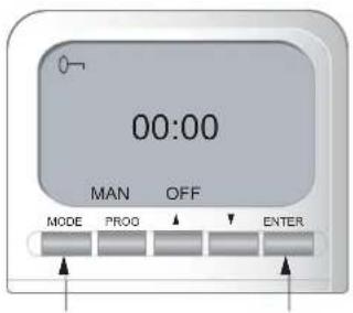
Fig.11
The Advance Function
When in AUTO mode, if ▲ is pressed for longer than 2 seconds the program will advance to the next programmed setting. When the ADVANCE function is active ADVANCE will be displayed on the screen (see Fig. 12).
To cancel advance press ▼ for longer than 2 seconds e.g. If present time is 14:00 and P1 ON is at 17:00 and P1 OFF is 19:00, if ▲ is held for 2 seconds then ADVANCE appears on the screen. The heater comes on and remains on until 19:00. ADVANCE
disappears from the screen at 17:00 as set program is then running.
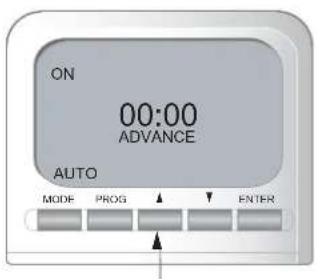
Fig. 12
Manual Control
- Power up the Controller by pressing the standby button (control knob). The 'ON' (green) light on the Controller and the 'AUTO' (yellow) light on the Receiver should illuminate. The 'AUTO' light on the Receiver indicates that the controller is functioning automatically.
- Ensure thr timer is in 'Man On' mode. See - 'Mode Seletion'
- Adjust the temperature control knob between the 'MAX' and 'MIN' positions to the desired temperature.
- If the room temperature is below the set desired temperature the controller will switch the appliance 'ON'. When the appliance is 'ON' the 'HEAT' (red) light on the Controller and Receiver units will be illuminated.
Boost Mode
The Boost function will override the Controller and the timer and run the appliance constantly for 30 minutes. The Boost mode can be activated by pressing the 'BOOST' button. The Controller in Boost mode will be indicated by all three lights on the Controller being illuminated. Boost mode can be de-activated by pressing the 'BOOST' button again.
Note: If the 'AUTO' (yellow) light on the Receiver is flashing the control unit is in fail mode (a link failure has occurred between the Controller and Receiver). If this occurs the appliance can be operated in a manual mode. To activate manual mode the front cover of the Receiver must be removed (see 'Installation'). The 'OVERRIDE' button will put the Controller in manual mode and the appliance will be switched 'ON', this is indicated by the 'HEAT' (Red) light On and the 'AUTO' (yellow) light Off on the Controller.
If a link failure has occurred, the Controller and Receiver must be paired again (see 'Unit Set-Up'). If this is not successful please contact your service agent.
Cleaning
WARNING: ALWAYS PLACE THE CONTROLLER IN STAND BY MODE BEFORE CLEANING.
Do not use detergents, abrasive cleaning powders or polish of any kind on the controller.
Wipe with a dry cloth to remove dust and a damp cloth (not wet) to clean off stains. Be careful not to allow moisture into the heater.
Recycling
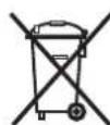
For electrical products sold within the European Community. At the end of the electrical products useful life it should not be disposed of with household waste. Please recycle where facilities exist. Check with your Local Authority or retailer for recycling advice in your country.
After sales service
Should you require after sales service or should you need to purchase any spares, please contact the retailer from whom the appliance was purchased. Please do not return a faulty product to us in the first instance as this may result in loss or damage and delay in providing you with a satisfactory service. Please retain your receipt as proof of purchase.
- RF Controller Unit: 24hr Controller & Receiver
- IMPORTANT : THESE INSTRUCTIONS SHOULD BE READ CAREFULLY AND RETAINED FOR FUTURE REFERENCE
- Important Safety Advice
- General
- Installation
- Controller
- Controller - see Fig. 2
- Receiver
- Receiver - see Fig. 4
- Receiver Wiring - see Fig. 5
- Unit Set-Up
- Operating Instructions
- Timer Mode Selection
- Set Time
- Set Program
- Key Lock
- The Advance Function
- Manual Control
- Boost Mode
- Cleaning
- Recycling
- After sales service
Brand : DIMPLEX
Model : RF24T
Category : Temperature regulator