
RXPW1 - Home Automation DIMPLEX - Free user manual and instructions
Find the device manual for free RXPW1 DIMPLEX in PDF.


| Product Type | Smart Home Thermostat / Controller |
| Brand | Dimplex |
| Model | RXPW1 |
| Dimensions (Approx.) | 120 mm x 80 mm x 25 mm |
| Weight (Approx.) | 150 g |
| Power Supply | 2x AAA batteries (not included) or USB-C 5V |
| Battery Life | Up to 1 year with typical use |
| Display Type | Backlit LCD |
| Connectivity | Wi-Fi 2.4 GHz, Bluetooth 5.0 |
| Compatibility | Works with Alexa, Google Assistant, HomeKit |
| Main Functions | Temperature control, scheduling, remote access via app, smart scene integration |
| Operating Temperature Range | 0°C to 40°C (32°F to 104°F) |
| Sensor Accuracy | ±0.5°C |
| Control Method | Touch screen, mobile app, voice commands |
| Security Features | Child lock, low battery alert, overheat protection |
| Cleaning and Maintenance | Wipe with a soft, dry cloth; do not use liquids or abrasives |
| Spare Parts Availability | Batteries only; internal components not user-replaceable |
| Repairability Index | Not applicable (sealed unit) |
Frequently Asked Questions - RXPW1 DIMPLEX
User questions about RXPW1 DIMPLEX
0 question about this device. Answer the ones you know or ask your own.
Ask a new question about this device
Download the instructions for your Home Automation in PDF format for free! Find your manual RXPW1 - DIMPLEX and take your electronic device back in hand. On this page are published all the documents necessary for the use of your device. RXPW1 by DIMPLEX.
USER MANUAL RXPW1 DIMPLEX
RXPW1 - 7 Day Timer/Programmer
TIDN7DP001
Issue 0
IMPORTANT: THESE INSTRUCTIONS SHOULD BE READ CAREFULLY AND RETAINED FOR FUTURE REFERENCE
General
The RXPW1 can only be used in the PLX05 electronic range of heaters.
They offer either individual programming (each individual heater has a programming module) or group programming from a master heater through the pilot wire. Group programming can drive up to 10 slave heaters.
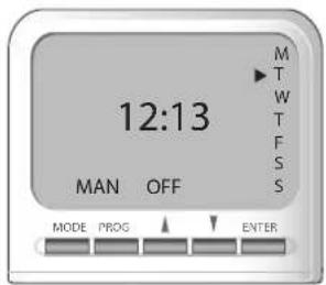
Fig. 1
Two heating positions are offered: comfort and off, with temperatures set using the controls on the heater.
For default Screen see Fig. 1.
Installation
The RXPW1 is rated at 230V.
- Switch the heater off.
-
Using a narrow bladed screwdriver, carefully release the cover from the slot on right hand side of the thermostat on the Panel Heater.
-
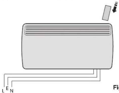
Remove the 7-day plug in timer from it's box and plug it into the slide in compartment now exposed - see Fig. 2. Insert the programmer fully so that it clicks into position. Switch the heater back on at the mains supply.
natural_image
Diagram of a heating unit with labeled terminals (L, E, N) and a small panel, no text or symbols present.Fig. 2
Individual Programming
Fit one programmer to each EPX heater. (Note: When the heater is installed, the black pilot wire in the mains supply cable should be trimmed back in accordance with the Installation Instructions.
Programming for a Zone
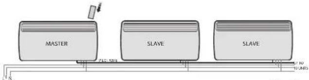
The heater containing the RXPW1 is the Master heater and connected by the black pilot wire to the Slave heaters. The Master heater determines the Program and heating levels for all the heaters (Comfort and Off), but the actual comfort temperature should still be set on each individual heater (see EPX Panel Heater instructions). The master heater will switch between Comfort and Off according to the program.
Electrical Connection Master/Slave Heaters
DO NOT connect the BLACK (PILOT) SIGNAL WIRE to earth. When the programmer drives other heaters, connect the pilot wire from the 'MASTER' unit to the pilot wire of a 'SLAVE' heater and then from one 'SLAVE' heater to another (in series) - see Fig. 3.
flowchart
graph LR
    A["MASTER"] --> B["PLC-MSR"]
    B --> C["SLAVE"]
    C --> D["SLAVE"]
    D --> E["Ground"]
    style A fill:#f9f,stroke:#333
    style C fill:#ccf,stroke:#333
    style D fill:#cfc,stroke:#333
Fig. 3
Any 240V insulated cable may be used to link pilot wires around the ring main. The signal current is low. Suitable connections would be either an additional single core wire marked or colour coded appropriately or use a 4 core cable throughout the heater ring.
Operating Instructions
The RXPW1 can be programmed either inserted directly into the heater or out of the heater. If choosing the latter option, the cassette must be first left in the heater for 2 days to charge the battery. Remember that the battery only lasts for 24 hours.
Problem Solving
In the event that no display appears on your 7-day timer do the following :
- Press any button to reactivate the display. Failing this -
- Return to the heater to charge battery (internal battery lasts for 24 hours when timer is removed from heater). Display will appear immediately but battery will be fully charged in 2 days.
Mode Selection
There are three different operating modes. Press MODE to cycle through these:
MAN OFF - heating is permanently Off – see Fig. 4. This is also the default screen.
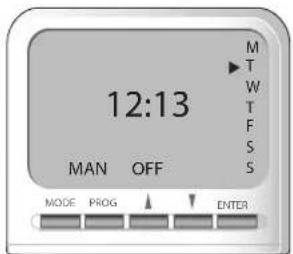
Fig. 4
MAN ON - heating is permanently On - see Fig. 5.
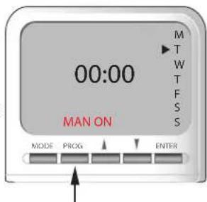
Fig. 5
AUTO - runs the programmed times - see Fig. 6.
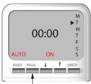
Fig. 6
Set Time
Press the PROG key once (from default display) to set time.
The Ⓞ appears (see Fig. 7) on the screen and the hours can be set using the ▲ keys. Press ENTER when finished setting the hours.
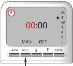
Fig. 7
Set minutes using the ▲ keys and press ENTER.
Then choose the day from Mon to Sun using the ▲▼keys and press ENTER to exit. Time and Day are now set.
Set Programme
The timer can only be programmed in 2 blocks i.e.
1st Block - Weekdays: Mon-Fri Press PROG twice (see Fig. 8). The Weekday programs are now ready to be set (starting with P1 ON, where P1 ON is the first ON time setting) go to 'a)' below:
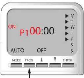
Fig. 8
2nd Block - Weekends: Sat & Sun
Press PROG twice and then press MODE once (see Fig. 9). The Weekend programs are now ready to be set (starting with P1 ON, where P1 ON is the first ON time setting), go to 'a)' below: a) set P1 ON time:
Set the hours using ▲ and press ENTER. Then set the minutes using ▲ and press ENTER.
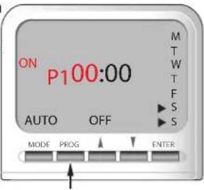
Fig. 9
Note: Time in minutes can only be set in 10 minute blocks.
Then set P1 OFF time:
Set the hours using ▲▼ and press ENTER.
Then set the minutes using ▲▼ and press ENTER. If only one program is required, press PROG now to return to default display OR
b) set P2 ON and OFF times: repeat procedure as 'a)' above.
c) set P3 ON and OFF times: repeat procedure as 'a').
d) set P4 ON and OFF times: repeat procedure as 'a').
After P4 Weekday OFF time has been set, the
User will be prompted to set P1 ON time for Weekends.
After P4 Weekend OFF time has been set the default Screen is displayed.
At any time while programming the timer, pressing the PROG button, this will exit to the default display. Timer must be in AUTO mode to run Set Programs.
NOTE: To cycle quickly from weekdays to weekends press the MODE button. There are 4 programs for weekdays and 4 for weekends.
Key Lock
To lock the keypad press ENTER and release, then press MODE within 1 second. The key symbol 0-will appear on the screen when the keypad is locked - see Fig. 10. To unlock the keypad repeat the action above. If any of the buttons on the keypad are pressed when it is locked, the light will automatically come on.
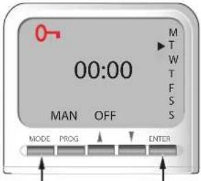
Fig. 10
The Advance Function
When in AUTO mode, if ▲ is pressed for longer than 2 seconds the program will advance to the next programmed setting. When the ADVANCE function is active ADVANCE will be displayed on the screen - see Fig. 11.
To cancel ADVANCE press ▼ for longer than 2 seconds
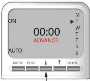
Fig. 11
e.g. If present time is 14:00 and P1 ON is at 17:00 and P1 OFF is 19:00, if ▲ is held for 2 seconds then ADVANCE appears on the screen. The heater comes on and remains on until 19:00. ADVANCE disappears from the screen at 17:00 as set program is then running.
Brand : DIMPLEX
Model : RXPW1
Category : Home Automation