
ECS250HP40A-580 - Uncategorized DIMPLEX - Free user manual and instructions
Find the device manual for free ECS250HP40A-580 DIMPLEX in PDF.


| Product Type | Heat pump cylinder with integrated 40L buffer |
| Model | ECS250HP40A-580 |
| Capacity (Total) | 250 L (cylinder 210 L + buffer 40 L) |
| Hot Water Capacity | 242 L |
| Height | 2025 mm |
| Outer Diameter | 580 mm |
| Weight (Empty) | 66.5 kg |
| Weight (Full) | 316.5 kg |
| Energy Rating | B |
| Standing Loss | 66 W |
| Materials (Inner Cylinder) | Duplex stainless steel LDX2101 |
| Materials (Outer Shell) | HIPS (recycled material) |
| Insulation | 60 mm PU foam (GWP=1, ODP=0) |
| Maximum Operating Pressure | 3 bar |
| Maximum Potable Water Temperature | 70 °C |
| Maximum Heating Water Temperature | 95 °C |
| Cold Water Supply Min. Dynamic Pressure | 1.5 bar |
| Cold Water Supply Max. Pressure | 12 bar |
| Connections (Cold Water Inlet & Hot Water Outlet) | 22 mm stainless steel |
| Connections (Coil Flow & Return) | 28 mm stainless steel |
| Heat Pump Coil Surface Area | 3.0 m² |
| Heat Pump Coil Performance | 47 kW |
| Immersion Heater | 1 3/4" BSP, 3 kW @ 240 V |
| Thermostatic Control (Direct) | Integral immersion heater thermostat and cut-out |
| Thermostatic Control (Indirect) | Integral twin thermostat (10-70 °C) and cut-out (~85 °C) |
| Safety Components | 3 bar PRV, 6 bar ERV, 1/2" T&P valve (7 bar/90 °C) |
| Approvals | KIWA No. 1309706 |
| Warranty (Inner Cylinder) | 25 years |
| Warranty (Immersion Heaters) | 2 years (excluding limescale effects) |
| Warranty (Other Components) | 2 years (excluding expansion vessel membrane) |
Frequently Asked Questions - ECS250HP40A-580 DIMPLEX
User questions about ECS250HP40A-580 DIMPLEX
0 question about this device. Answer the ones you know or ask your own.
Ask a new question about this device
Download the instructions for your Uncategorized in PDF format for free! Find your manual ECS250HP40A-580 - DIMPLEX and take your electronic device back in hand. On this page are published all the documents necessary for the use of your device. ECS250HP40A-580 by DIMPLEX.
USER MANUAL ECS250HP40A-580 DIMPLEX
Heat Pump Cylinders With Integrated 40l Buffer
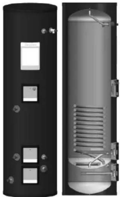
natural_image
Two views of a cylindrical industrial water heater with internal cooling system (no text or symbols visible)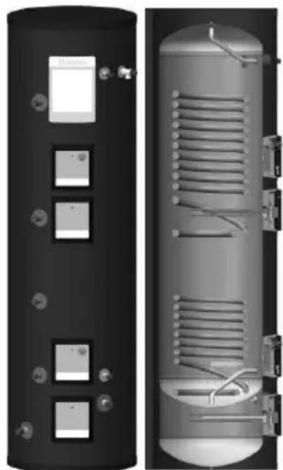
natural_image
Two views of a cylindrical industrial water heater with internal heat exchanger (no text or symbols visible)EC-Eau Cylinder Range
Installation and User Instructions
Important - This Manual Must Remain with the User After Installation!


GDC Group is a licensed member of the Benchmark Scheme which aims to improve the standards of installation and commissioning of domestic heating and hot water systems in the UK and to encourage regular servicing to optim safety, efficiency and performance.
Benchmark places responsibilities on both manufacturers and installers. The purpose is to ensure that customers are provided with the correct equipment for their needs, that it is installed, commissioned and serviced in accordance with the manufacturer's instructions by competent persons and that it meets the requirements of the appropriate Building Regulations. The Benchmark Checklist can be used to demonstrate compliance with Building Regulations and should be provided to the customer for future reference.
Installers are required to carry out installation, commissioning and servicing work in accordance with the Benchmark Code of Practice which is available from the Heating and Hot Water Industry Council who manage and promote the Scheme. Visit www.centralheating.co.uk for more information.
The HWA Charter requires that all members adhere to the following:
- supply fit for purpose products clearly and honestly described
- supply products that meet, or exceed appropriate standards and building and water regulations
- provide pre and post sales technical support
• provide clear and concise warranty details to customers
For further information on the HWA Charter Membership, please refer to th HWA website www.hotwater.org.uk'
All Glen Dimplex cylinders are certified by KIWA, for further information on this regulation body please refer to the KIWA website www.kiwa.co.uk'
0 Overall View
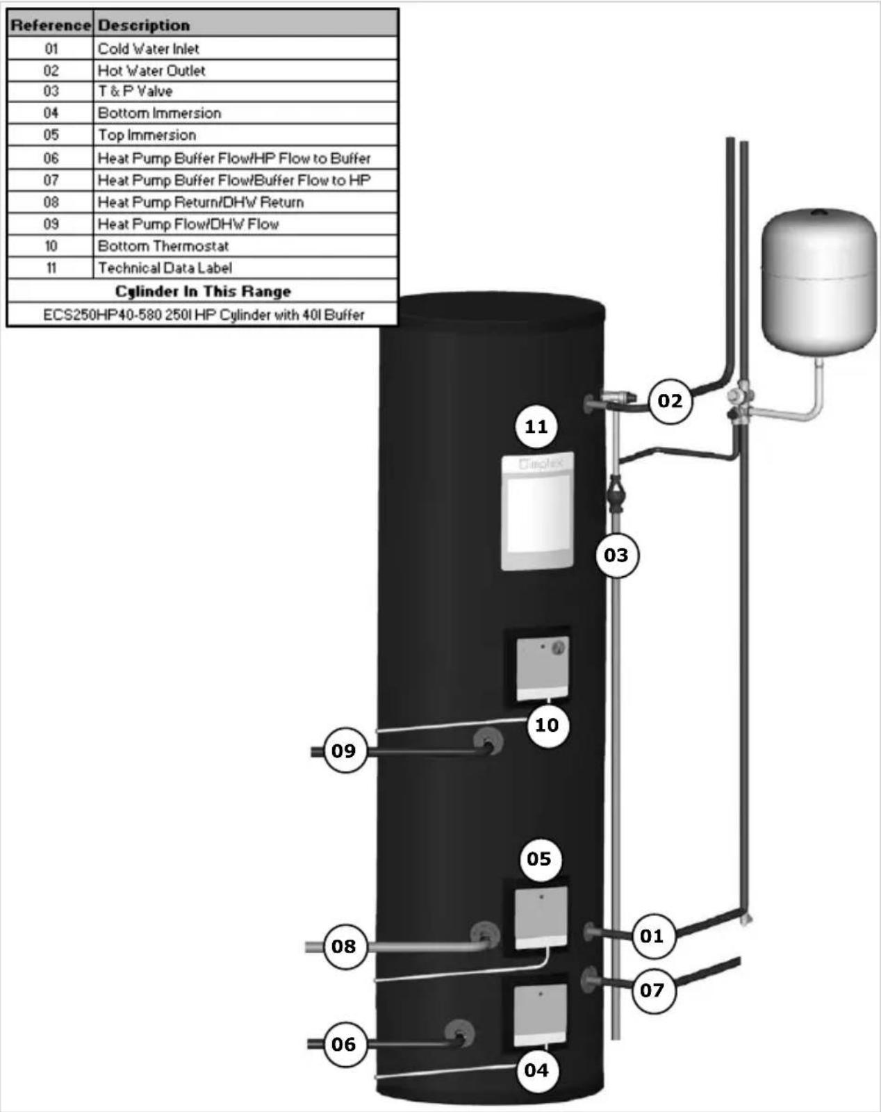
Figure 1: Overall View of Heat Pump with Buffer Cylinder Installation Process
1 Contents
0 Overall View....3
1 Contents......4
2 Introduction....8
3 Scope of Delivery....9
4 Pre-Installation Advice.... 10
4.1 Risk Assessment 10
4.2 Siting Considerations....10
4.3 Cold Water Supply 11
4.4 Building Regulation G3 Discharge Requirements 12
4.4.1 Discharge Pipe D2....13
4.4.2 Worked Example....14
4.4.3 Termination of Discharge Pipe....15
4.5 Limitations 16
5 Installation.... 16
5.1 Cold Water Inlet with Inlet Control Group....16
5.1.1 Correctly Site the Cylinder....16
5.1.2 Install the Inlet Group 16
5.1.3 Expansion Vessel 16
5.1.4 Balanced Cold Water Supply 17
5.1.5 Drain Valve 17
5.2 Hot Water Outlet....17
5.2.1 Thermostatic Mixing Valve....17
5.2.2 Pipe Insulation....17
5.3 Discharge Pipes from Safety Devices 17
5.3.1 Discharge Pipe D1....17
5.3.2 Discharge Pipe D2....18
5.3.3 Tundish....18
5.4 Immersion Heater....19
5.5 Coil Flow Connections....19
5.6 Coil Return Connections....19
5.7 HP Flow to Buffer 19
5.8 Buffer Flow to HP 19
5.9 Cylinder Thermostat & Heat Pump Sensor Connections 20
5.9.1 Thermostat Connections....20
5.9.2 Connection of the Sensor 21
5.10 Connection of Secondary Return 24
5.11 Heat Pump and Buffer Cylinder Schematic....25
6 Commissioning 26
7 Maintenance.... 27
8 Spare Parts.... 29
9 Technical Data and Product Fiche.... 30
9.1 Cylinder Heat Exchanger Pressure Drop 33
9.2 Cylinder Attainable Temperature Curves ....34
10 User Instructions.... 35
10.1 General....35
10.2 Operation....35
10.2.1 Water Temperature Direct Electric Heating 36
10.2.2 Water Temperature Auxiliary Heating 37
10.3 Maintenance....37
10.4 Troubleshooting 38
Precaution: "This appliance can be used by children aged from 8 years and above and persons with reduced physical sensory or mental capabilities or lack of experience and knowledge if they have been given supervision or instruction concerning use of the appliance in a safe way and understanding the hazards involved. Children shall not play with the appliance. Cleaning and user maintenance shall not be made by children without supervision."
Note: Between the inlet group and the cold water inlet on the cylinder NO isolating device may be fitted, as by doing so important safety devices could be isolated!

It is important to check the pre-charge pressure of the expansion vessel membrane before filling the cylinder. The pre-charge should be greater than or equal to 3 bar.

It is important that the tundish is positioned away from any electrical components.
Note: Means for electrical disconnection must be incorporated in the fixed wiring in accordance with the wiring rules.

Before removing the cover from the immersion heater isolate appliance using isolating switch! Danger of electrical shock! Only use suitable electrically insulated equipment
when working inside immersion housing.
Note: The cylinder must be filled with water before switching on the immersion heater. Failure to do so will damage the element and void any guarantee on the product.
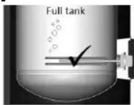
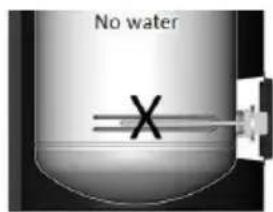
Never operate cylinder without water or element can burn out

The maintenance of this appliance must be carried out by a suitably qualified person only. It is recommended to maintain the unit on an annual basis. Isolate all electrical supplies from the unit before commencing work. Danger of electrical shock!

CLEANING INSTRUCTIONS:
Clean outer cladding of cylinder with a soft cloth dampened with warm water only. Do not use abrasive or aggressive cleaning materials, such as alcohol or petroleum based solvents, as this may damage the surface of the product.
If an electronic copy of this manual should be required, please contact the manufacturer at the address at the back of this manual.
2 Introduction
Thank you for choosing a Dimplex product. The EC-Eau heat pump cylinders are specified with large, high surface area heat exchangers, specifically sized to match the requirements of Dimplex heat pumps. They boast 60mm of low GWP insulation foam, together with 100% recyclable stainless steel inner components and a sleek black, hard wearing outer shell manufactured from completely recycled materials. For more detailed information on product features, please see the Technical Data section in this manual.
NOTE: This product has been designed specifically for the purpose of delivering heated, domestic and sanitary hot water as part of a pressurised water heating system. The package is provided with fittings that comply with Section G3 of Building Regulations.
WARNING: Dimplex cannot take responsibility for ensuring safe operation of the appliance outside of the scope of intended use.
3 Scope of Delivery
Please ensure you check the scope of delivery below before signing any delivery documentation. Claims for missing or damaged parts after signing for the delivery will not be accepted.
| Scope of delivery | ||
| Cylinder nominal volume | 250/40 l | |
| Cylinder with one 3kW immersion * | √ | |
| 40l Buffer vessel with one 3kW immersion * | √ | |
| T+P valve * |  | 1/2", 7bar/90°C |
| Inlet control group consisting of:- |  | √ |
| · in line strainer | ||
| · 3 bar PRV | ||
| · 6 bar ERV | ||
| · non-return valve | ||
| · balanced cold water supply port | ||
| · 22mm connection for expansion vessel | ||
| 28mm motorised two port valve ** |  | √ |
| Expansion vessel with fixing kit and connection hose |  | 24 l |
| Tundish |  | 15mm/22mm |
| Installation & User Instructions x 1 |  | √ |
| Terms and conditions x 1 |  | √ |
Table 1: Scope of Delivery for Heat Pump with Buffer Cylinders
* These items are supplied factory fitted
** Only part of the scope of delivery when not supplied as a Dimplex Heat Pump package
4 Pre-Installation Advice
Please read the following section carefully before commencing installation. If in any doubt, please call the appropriate help desk.
Disregarding the instructions given in this manual in its entirety and any relevant regulations, standards and codes of practice will void the guarantee of this product.
Handling – depending on the size of the unit and access to its installation location, consideration must be given to the handling of the unit. Please note that handling, installation and use of this product is subject to the Health and Safety at Work Act.
If the unit is not installed immediately, it should remain in its protective packaging with all pipe protectors/end caps applied to prevent damage and dirt deposit inside the cylinder and the coils.
Pipe Work – the pipe runs should be executed as short as possible, unused pipe work should be removed and all remaining pipe work should be lagged in accordance with regulatory requirements to prevent heat loss and the formation of condensation.
Taps and Fittings – all taps and fittings incorporated in the unvented system should have a rated operating pressure of 0.6 MPa (6 bar) or above.
4.1 Risk Assessment
The compilation of a risk assessment is strongly recommended before installing the product. The following areas require particular consideration in addition to the information required by the Health and Safety at Work Act.
- scalding: where appropriate or required by law a thermostatic mixing valve is to be fitted to the hot water outlet of the cylinder (see also water borne organisms).
- explosion: the unit is fully equipped with all relevant safety equipment to comply with current regulations. The correct design and function has been verified by independent third party testing. The correct application thereof is the responsibility of the competent installer.
- water borne organisms (i.e. Legionella): if applicable a risk assessment should be carried out following the recommendations outlined in the Approved Code of Practice L8.
- the user preference must be considered when commissioning the system, in particular when adjusting the auxiliary system temperature and timer settings.
4.2 Siting Considerations
When choosing a suitable location for the cylinder the following aspects should be considered:
- structural integrity
- access for installation, operation, maintenance and replacement
- routing of discharge pipe work
- access to water mains supply, hot and cold water distribution pipe work
- access to suitable electricity supply
- location in relation to remaining system components such as auxiliary heating system
- frost protection
The heat pump cylinder range is designed to be floor standing, vertically mounted, indoors and in a frost free environment. The cylinder may be located on any flat and level surface, provided it is sufficiently robust to support the weight of the cylinder when full of water (please see technical data) and suitably accessible for replacement/maintenance without specialist tools or lifting equipment as this will void the warranty conditions.
The position and orientation of the cylinder should be such that easy access is provided for servicing the controls. A minimum distance of 400mm in front of the immersion is recommended, to allow the replacement of the immersion heater should the need arise. When installing the cylinder all labels should be clearly visible and ensure that no pipework hinders any work to be carried out on the various cylinder components.
Particular care must be taken when placing the cylinder in a garage or outbuilding. All exposed pipe work must be correctly insulated to avoid frost damage.

CLEANING INSTRUCTIONS: Clean outer cladding of cylinder with a soft cloth dampened with warm water only. Do not use abrasive or aggressive cleaning materials, such as alcohol or petroleum based solvents, as this may damage the surface of the product.
4.3 Cold Water Supply
For satisfactory and safe performance of the unvented cylinder the water supply must meet the following criteria:
| Minimum dynamic pressure | 150 kPa(1.5 bar) |
| Maximum inlet supply pressure | 1200 kPa(12 bar) |
| Minimum flow rate | 15 l/min |
| Max. chlorine content | 250mg/L |
| Max. water hardness | 200mg/L |
The following instructions have to be followed when installing the cold water mains supply to the cylinder:
- The cold water supply to the cylinder must come directly from the cold water mains after the mains stop valve to the property.
- The cold water inlet pipe work should have at least an inside diameter of 19mm and should meet the requirements of the water regulations for the supply of wholesome water.
Dimplex recommend an annual maintenance inspection is carried out on the domestic hot water cylinder. In hard water areas this should include inspection of the heat exchanger and immersion heater, [above 120ppm or 120mg/l]. A local water treatment company should be able to offer free water quality testing. The heating elements may require periodic de-scaling. The installer should do this as part of a maintenance agreement.
If required, precautions can be taken to minimise effects of water hardness, i.e. installation of water conditioner or water softener. These devices should be installed in hard water areas where high water storage temperatures are required, i.e. greater than 60°C storage temperatures, particularly when water hardness exceeds 200ppm. Should the water cylinder require de-scaling, this must be performed by a qualified technician.
4.4 Building Regulation G3 Discharge Requirements
As part of the requirements of Building Regulation G3 any discharge from an unvented system should be conveyed to where it is visible, but will not cause danger to persons in or about the building. The tundish and the discharge pipes should be fitted in accordance with the requirements of Building Regulation approved document G3, (England and Wales), Part P of Northern Ireland and Standard 4.9 of Scotland.
4.4.1 Discharge Pipe D2
The discharge pipe (D2) from the Tundish should:
- "have a vertical section of pipe at least 300mm long below the tundish before any elbows or bends in the pipework and be installed with a continuous fall of at least 1 in 200 thereafter."
The discharge pipe (D2) should be made of:
- "metal; or other material that has been demonstrated to be capable of safely withstanding temperatures of the water discharged and is clearly and permanently marked to identify the product and performance standard"
Dimplex strongly recommends the use of metal pipework only and Dimplex does not take responsibility for any damage caused from discharges.
The discharge pipe D2 should be at least one pipe size larger than the nominal outlet size of the safety device unless its total equivalent hydraulic resistance exceeds that of a straight pipe 9m long, i.e. for discharge pipes between 9m and 18m the equivalent resistance length should be at least two sizes larger than the nominal outlet size of the safety device; between 18 and 27m at least 3 sizes larger, and so on; bends must be taken into account in calculating the flow resistance. See Figure 2, Table 2 and the worked example.
Note: An alternative approach for sizing discharge pipes would be to follow Annex D, section D.2 of BS 6700:2006 + A1:2009).
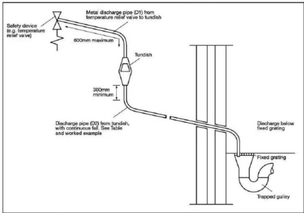
Figure 2: Typical Discharge Pipe Arrangement
| Valve outlet size[-] | Minimum size of discharge pipe before tundish[mm] | Minimum size of discharge pipe after tundish[mm] | Maximum allowed length of pipe after tundish[m] | Length to be subtracted for each elbow or bend[m] |
| G1/2 | 15 | 22 | 9 | 0.8 |
| 28 | 18 | 1.0 | ||
| 35 | 27 | 1.4 | ||
| G3/4 | 22 | 28 | 9 | 1.0 |
| 35 | 18 | 1.4 | ||
| 42 | 27 | 1.7 | ||
| G1 | 28 | 35 | 9 | 1.4 |
| 42 | 18 | 1.7 | ||
| 54 | 27 | 2.3 |
Table 2: Sizing of Copper Discharge Pipe "D2" for Common Temperature Relief Valve Outlet Sizes
4.4.2 Worked Example
This example is for a G½ temperature relief valve with a discharge pipe (D2) (as fitted on 125 to 300L cylinders) having 4 No. 22mm elbows and length of 7m from the tundish to the point of discharge.
From Table 2, the maximum resistance allowed for a straight length of 22mm copper discharge pipe
(D2) from a G^1/2 temperature relief valve is 9.0m. Subtract the resistance for 4 No. 22mm elbows at 0.8m each = 3.2m.
Therefore the maximum permitted length equates to 5.8m, which is less than the actual length of 7m, therefore calculate the next largest size.
Maximum resistance allowed for a straight length of 28mm copper discharge pipe (D2) from a G½ temperature relief valve is: 18m
Subtract the resistance for 4 No. 28mm elbows at 1.0m each = 4m
Therefore the maximum permitted length equates to 14m.
As the actual length is 7m, a 28mm (D2) copper pipe will be satisfactory.
- Where a single common discharge pipe serves more than one system, it should be at least one pipe size larger than the largest individual discharge pipe (D2) to be connected.
- The discharge pipe should not be connected to a soil discharge stack unless the soil discharge stack is capable of safely withstanding temperatures of the water discharged, in which case, it should:
- contain a mechanical seal, which allows water into the branch pipe without allowing foul air from the drain to be ventilated through the tundish.
- there should be a separate branch pipe with no sanitary appliances connected to it.
- if plastic pipes are used as branch pipes carrying discharge from a safety device, they should be either polybutalene (PB) or cross-linked polyethylene (PE-X) complying with national standards.
- be continuously marked with a warning that no sanitary appliances should be connected to the pipe.
4.4.3 Termination of Discharge Pipe
- "The discharge pipe (D2) from the tundish should terminate in a safe place where there is no risk to persons in the vicinity of the discharge."
- Examples of acceptable discharge arrangements are:
- "to a trapped gully with the end of the pipe below a fixed grating and above the water seal;
- downward discharges at low level; i.e. up to 100mm above external surfaces such as car parks, hard standings, grassed areas etc. are acceptable providing that a wire cage or similar guard is positioned to prevent contact, whilst maintaining visibility; and,
- discharges at high level: e.g. into a metal hopper and metal downpipe with the end of the discharge pipe clearly visible or onto a roof capable of withstanding high temperature discharges of water and 3m from any plastic guttering system that would collect such discharges."
Note: As the discharge would consist of high temperature water and steam, asphalt, roofing felt and non-metallic rainwater goods may be damaged by such discharges.
4.5 Limitations
- The heat pump must be specified correctly, to ensure it is compatible with the model of cylinder installed. This is to prevent the heat pump malfunctioning when preparing domestic hot water.
- The heat exchangers in this range of cylinders have been specifically designed for heat pump applications. Great care must be taken if using these cylinders with other heat sources, due to the heat exchange capacity of the product.
5 Installation
5.1 Cold Water Inlet with Inlet Control Group
5.1.1 Correctly Site the Cylinder
Install the cylinder in an appropriate location, ensuring all of the recommendations have been considered (see chapter 4.2).
5.1.2 Install the Inlet Group
The inlet group regulates the pressure of the incoming mains water supply to the cylinder and removes any debris that might be water borne.
Note: Between the inlet group and the cold water inlet on the cylinder NO isolating device may be fitted, as by doing so important safety devices could be isolated!
5.1.3 Expansion Vessel
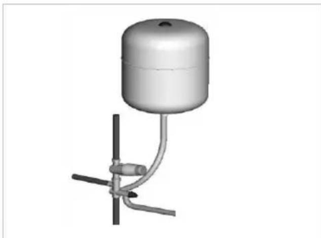
The expansion vessel is mandatory on all EC-Eau cylinders and can be connected directly to the cold water inlet group, utilising the flexible hose supplied with the vessel. The expansion vessel should always be fitted in accordance with the manufacturer's instructions. No isolating device should be fitted between the water cylinder and the cold water inlet group.
Furthermore, it is recommended to mount the vessel higher than the cylinder to avoid having to drain the cylinder when maintaining and replacing the expansion vessel.
natural_image
3D rendering of a cylindrical water pump mounted on a vertical pole with tubing (no text or symbols visible)Figure 3: Connection of the Expansion Vessel to the Inlet Group

It is important to check the pre-charge pressure of the expansion vessel membrane before filling the cylinder. The pre-charge should be greater than or equal to 3bar.
Note: The expansion vessel must be installed to the side of the expansion relief valve on the inlet group. To do this the blanking plug must be removed and the expansion vessel connected, as shown in Figure 4.
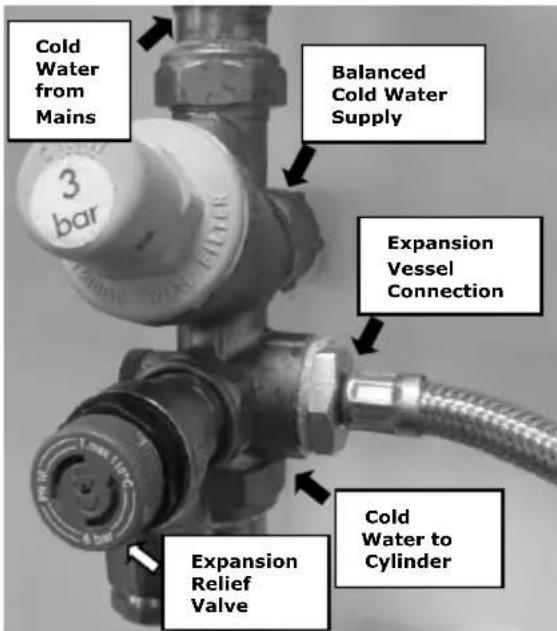
Figure 4: Detail Showing the Connection of the Expansion Vessel to the Inlet Group
5.1.4 Balanced Cold Water Supply
If balanced cold water supply is required a connection can be taken from the bottom of the inlet group.
5.1.5 Drain Valve
It is also recommended to install a drain valve (not supplied) in the lowest point of the cold water feed to the cylinder. This allows the cylinder to be drained in a controlled manner should this become necessary.
5.2 Hot Water Outlet
The hot water pipe work is to be directly connected to the hot water outlet connection on the cylinder, see Figure 1.
5.2.1 Thermostatic Mixing Valve
A thermostatic mixing valve may be required to limit the outlet temperature. In this case, the valve should be installed following the manufacturer's instructions, ensuring none of the safety equipment has been isolated, (i.e. make sure the connection to the thermostatic mixing valve is taken after the safety equipment of the inlet group).
5.2.2 Pipe Insulation
It is recommended to insulate the hot water pipe work from the cylinder to the outlets, to reduce the energy requirements for providing hot water. It is also recommended to insulate all other exposed pipework, such as the T&P to the tundish, the coil flow and return and the cold water inlet pipes.
5.3 Discharge Pipes from Safety Devices
- The temperature and pressure relief valve must be discharged directly or by way of a manifold via a short length of metal pipe (D1) into a tundish; and the discharge pipe must be installed in a continuously downward direction and in a frost free environment. Water may drip from the discharge pipe of the pressure relief device and this pipe must be left open to the atmosphere.
- The diameter of discharge pipe (D1) should not be less than the nominal outlet size of the safety device, e.g. temperature relief valve.
- Where a manifold is used it should be sized to accept and discharge the total discharge from all the D1 discharge pipes connected to it.
- The discharge pipe work from the expansion relief valve must be installed constantly falling to an open point of discharge. It is recommended to combine it with the discharge of the temperature and pressure relief valve.
Note: The T&P valve is pre-sealed and if moved the seal will be broken, should this occur, it will need to be resealed with an appropriate sealant (Dimplex part number R00836-1).
5.3.2 Discharge Pipe D2
For a detailed description of the discharge pipework D2 see chapter 4.4.1.
5.3.3 Tundish
- The tundish should be vertical, located in the same space as the unvented hot water storage system and be fitted as close as possible to, and lower than, the safety device, with no more than 600mm of pipe between the valve outlet and the tundish (see Figure 2).
- Discharge should be visible at the tundish, where discharges may not be apparent, e.g. in dwellings occupied by people with impaired vision or mobility, consideration should be given to the installation of a suitable safety device to warn when discharge takes place, e.g. electronically operated.
Note: To comply with the Water Supply (Water Fittings) Regulations, the tundish should incorporate a suitable air gap.

It is important that the tundish is positioned away from any electrical components.
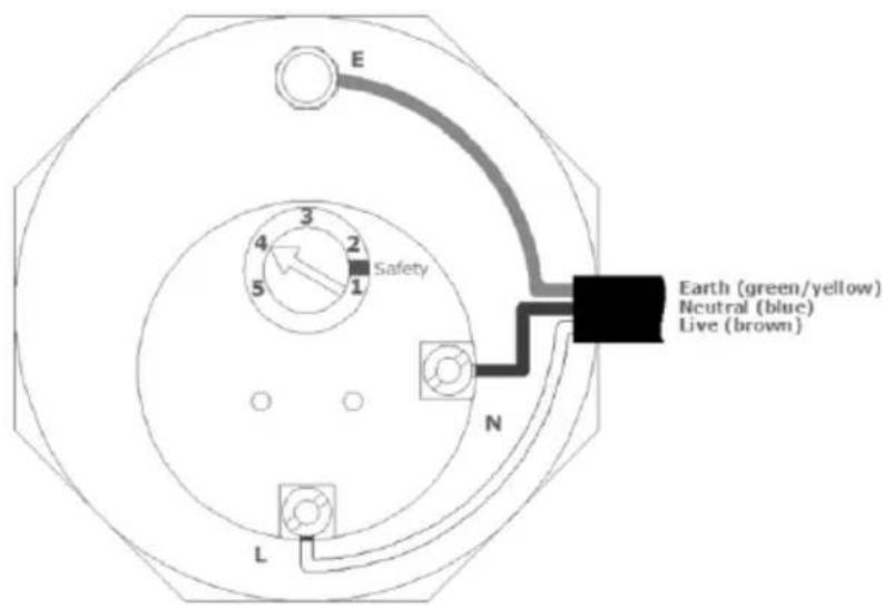
Figure 5: Wiring Diagram for Immersion Heater
5.4 Immersion Heater
The immersion heater has to be connected in accordance with IEE Wiring Regulations and the installer carrying out the work has to be suitably qualified.
It must be connected through a double pole isolating switch or suitable controller which must have a contact separation of at least 3mm in all poles.
The wiring diagram can be seen in Figure 5. For further details please see instructions provided with the immersion heater.
The immersion heater incorporates an independent non-self resetting over temperature cut-out. Should the over temperature cut-out operate, the reset pin will be pushed upwards, and become level or slightly proud of the cover at the position marked "Safety". Use a suitable sized implement to reset the pin by pushing it hard into its original position.
The immersion heater typically cannot be directly switched by the heat pump controller, but instead requires a relay. Note: Should it be necessary to remove the thermostat from the immersion element, ensure that the contacts are re-fitted correctly into the positions on the element. Failure to do so carries the risk of overheating the contacts and thus damaging the appliance.
The immersion heater thermostat must not be opened under any circumstances.
Note: The cylinder must be filled with water before switching on the immersion heater. Failure to do so will damage the element and void any guarantee.
5.5 Coil Flow Connections
If the flow connection is the highest point in the heat pump loop and if the system was not commissioned using a flush and fill pump, an adequate device for de-aeration must be installed.
5.6 Coil Return Connections
Equally, if the return connection is the lowest point in the heat pump loop, a suitable drain device should be installed. For location of connections see Figure 1.
It is recommended that the fittings used to connect to the cylinder are suitable for stainless steel, the flow and return should use 28mm compression fittings. Not all push fit fittings can be used – please check with your supplier. When using compression fittings, ensure that the connection is not over-tightened.
5.7 HP Flow to Buffer
The cylinder buffer flow connection must be connected to a three port valve which diverts flow between the buffer cylinder and DHW cylinder heating coil.
5.8 Buffer Flow to HP
The cylinder buffer flow to HP connection must be connected in series with the heat emitter system/under floor heating.
5.9 Cylinder Thermostat & Heat Pump Sensor Connections
To conform to building regulations, it is imperative that the heating water circulating pump(s) be installed through the cylinder twin thermostat(s).
Also, a two port valve(s) has to be wired after the thermostat, ensuring compliance with building regulations. This is applicable to each heat source entering the water cylinder.
Should a Dimplex Heat Pump be installed with the cylinder, it is sufficient to use the temperature sensor to control the heat input to the cylinder.
5.9.1 Thermostat Connections
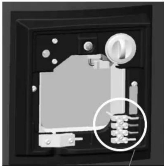
To access the thermostat connections, the cover panel should be removed.
natural_image
3D rendered mechanical component with a magnified inset showing internal components (no text or symbols visible)Thermostat terminal block - primary connections.
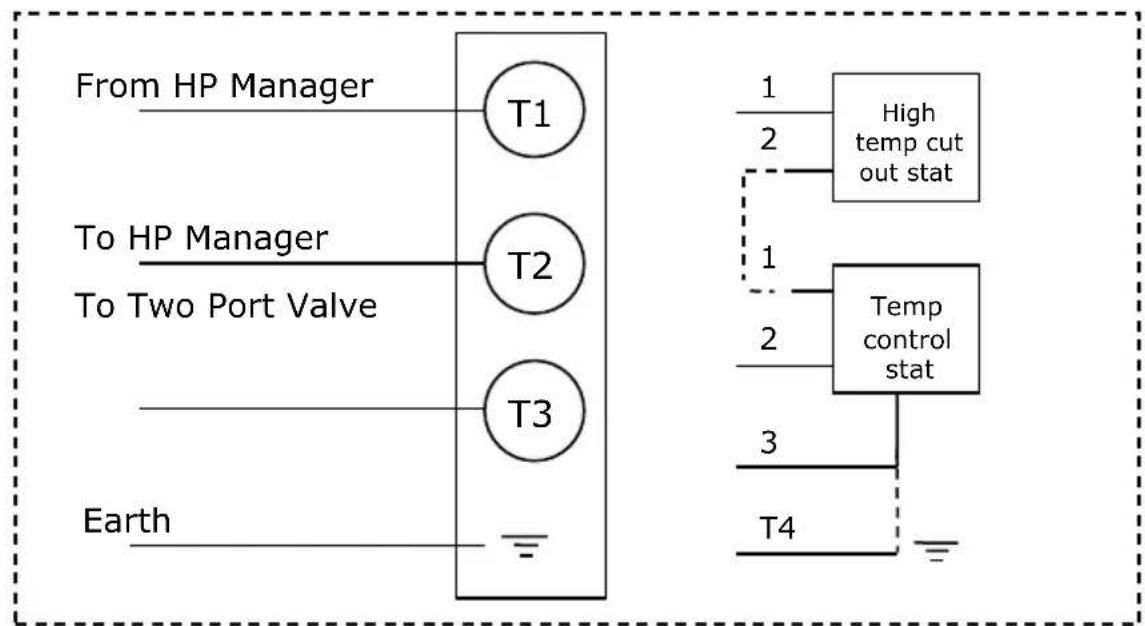
flowchart
graph TD
    A["From HP Manager"] --> B["T1"]
    C["To HP Manager"] --> D["T2"]
    E["To Two Port Valve"] --> D
    F["Earth"] --> G["T3"]
    B --> H["1"]
    D --> I["2"]
    G --> J["3"]
    H --> K["High temp cut out stat"]
    I --> L["Temp control stat"]
    J --> M["T4"]
NOTE: T1 and T2 must be connected to the heat pump control panel, see heat pump installation manual. T3 can replace T2 only when a normally open configuration is required.
Figure 6: Cylinder Thermostat Wiring Detail, Heat Pump
5.9.2 Connection of the Sensor
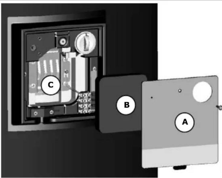
Step 1: Access the sensor mounting plate. To do this remove the Dual Cut Out cover plate (A) by removing the fixing screw and insulation foam (B) to access the sensor mounting plate (C). Remove the M5 fixing screws in the four corners of the plate.
Position to mount sensor T2
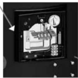
natural_image
Interior view of a vintage office or computer room with visible equipment and a clock (no text or symbols)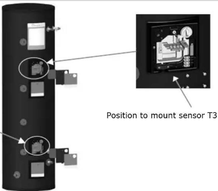
Step 2: If a T3 sensor is required repeats steps for mounting sensor T2, as shown in Step 1.
natural_image
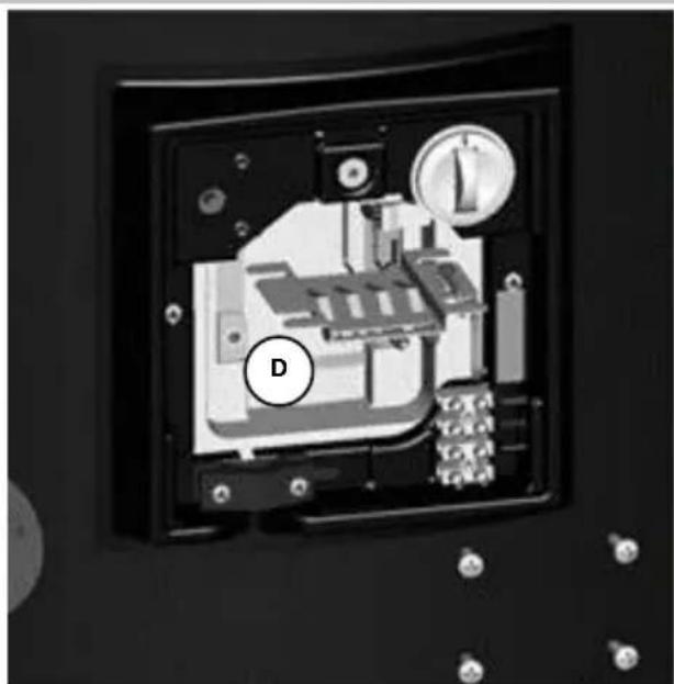
Interior view of a mechanical or electronic device with labeled component D, showing internal components and mounting holes (no readable text or symbols)Step 3: Orientate the sensor mounting plate to allow access to the phials (four clips in the centre of the sensor mounting plate). Be careful not to kink the capillaries that connect the thermostat bulbs. The sensor mounting plate will have two vacant slots for additional sensors (D).
natural_image
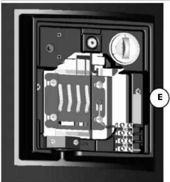
Interior view of a device showing internal components and a labeled component (E), no readable text or symbols present.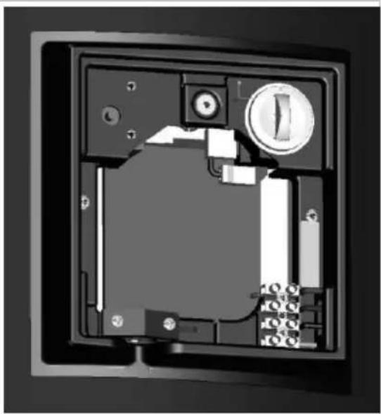
natural_image
Interior view of a device casing with internal components and mounting holes (no visible text or symbols)Step 4: Move the sensor mounting plate back into its fixing position. Be careful not to kink the capillaries that connect the thermostat bulbs. Fit the four M5 fixing screws into the cylinder bracket (E). Tighten the screws until the thermostat bulbs and heat pump sensor are held firmly against the wall of the inner cylinder.
Note: there should be no movement in the phials that are used to hold the bulbs and sensor. Care should be taken not to over tighten the screws.
Step 5: Replace the insulating foam over the sensor mounting plate.
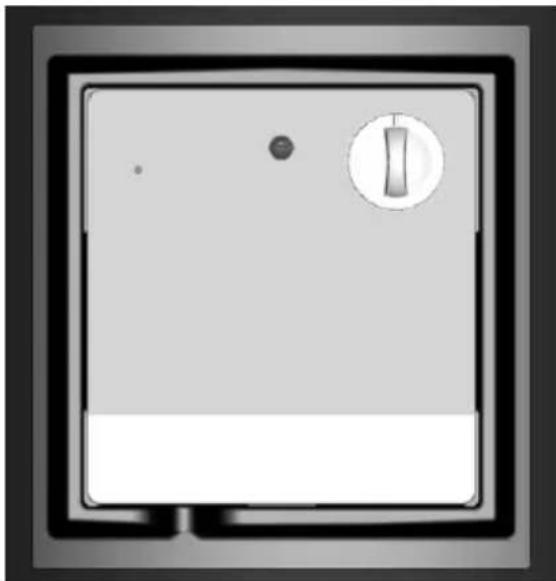
Step 6: Refit the Dual Cut Out cover plate. Enter the fixing tab into the slot provided at the base of the enclosure and fit the fixing screw.
natural_image
Front view of a gray appliance with a circular button and indicator light (no text or symbols visible)5.10 Connection of Secondary Return
For cylinders that do not have a dedicated secondary return connection, it is possible to install a secondary return by connecting a swept - T to the cold water inlet of the cylinder (see Figure 7).
The secondary return pipe should incorporate a check valve and a WRAS approved circulation pump; timer and thermostat to be provided separately. Where secondary return circuits are used, then an additional expansion vessel may be required.
The secondary return loop must avoid:
- stagnant water in long pipe runs
- long waiting times at draw off point for hot water
- undue water wastage
To minimise the energy consumption of the secondary return circuit and to ensure reliable operation it is important to consider:
- the control of the circulation pump to be time and temperature controlled
- the secondary return circuit pipe work to be insulated
- the secondary return pump to be of suitable material and specification
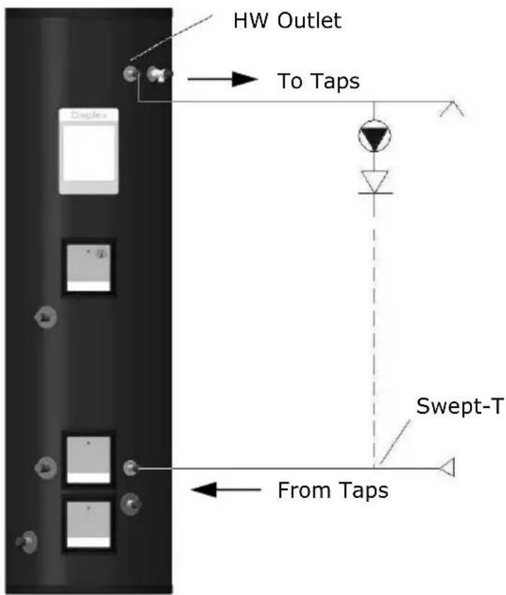
Figure 7: Secondary Return Loop
5.11 Heat Pump and Buffer Cylinder Schematic
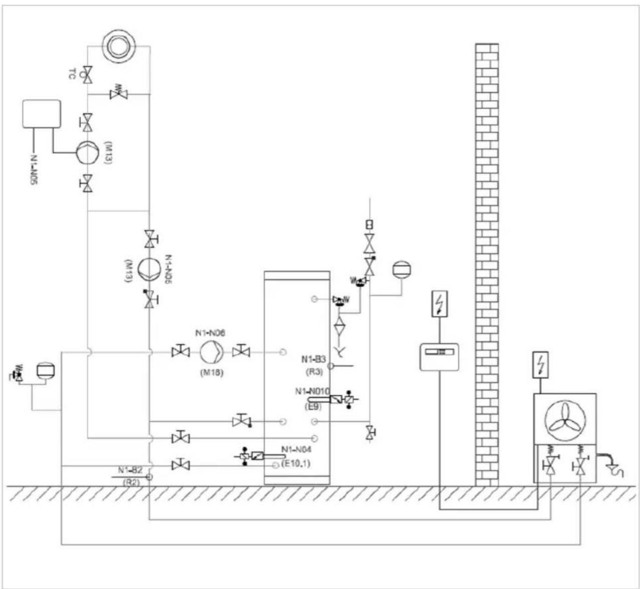
flowchart
graph TD
    A["SDIN5"] --> B["Valve"]
    C["TC"] --> D["Valve"]
    E["M13"] --> F["Valve"]
    G["N1-N05"] --> H["Valve"]
    I["N1-N06"] --> J["Valve"]
    K["N1-B3 (R3)"] --> L["Control Unit"]
    M["N1-N010 (E9)"] --> N["Control Unit"]
    O["N1-N04 (E10.1)"] --> P["Control Unit"]
    Q["N1-B2 (R2)"] --> R["Control Unit"]
    S["Wind"] --> T["Control Unit"]
    U["Wind"] --> V["Control Unit"]
    W["Wind"] --> X["Control Unit"]
    Y["Wind"] --> Z["Control Unit"]
    AA["Wind"] --> AB["Control Unit"]
    AC["Wind"] --> AD["Control Unit"]
    AE["Wind"] --> AF["Control Unit"]
    AG["Wind"] --> AH["Control Unit"]
    AI["Wind"] --> AJ["Control Unit"]
    AK["Wind"] --> AL["Control Unit"]
    AM["Wind"] --> AN["Control Unit"]
    AO["Wind"] --> AP["Control Unit"]
    AQ["Wind"] --> AR["Control Unit"]
    AS["Wind"] --> AT["Control Unit"]
    AU["Wind"] --> AV["Control Unit"]
    AW["Wind"] --> AX["Control Unit"]
    AY["TD"] --> AZ["Valve"]
    BA["N1-B2 (R2)"] --> BB["Control Unit"]
Figure 8: Heat Pump and Buffer Cylinder Schematic
6 Commissioning
At the time of commissioning, complete all relevant sections of the Benchmark Checklist located on the inside back pages of this document.
The following commissioning procedures only detail the required steps to be taken for the potable water loop and not for the heat pump loop:
1) Before making any mains connections to the inlet control group, flush the mains pipework out to ensure all debris has been removed so as not to damage the strainer within the combination valve.
2) Make final mains connection on combination valve and check all connections and joints to ensure they have been tightened and secured correctly.
3) Before turning on the mains supply to the cylinder a hot water tap should be opened, preferably on the same floor or the floor below where the cylinder is located.
4) Check the pre-charge in the expansion vessel and ensure it is at least 3 bar. Note actual pressure on label on expansion vessel.
5) Turn on the supply to the cylinder and fill until water runs from the open hot
water tap. Continue to flush the system until all debris has been removed.
6) Close the hot water tap.
7) Check all joints for leaks, even those not having been altered especially when replacing a vented cylinder.
8) Open temperature and pressure relief valve to ensure proper discharge and check after closing that valve is not dripping.
9) Open expansion relief valve to ensure proper discharge and check after closing that valve is not dripping.
10) Check all shower outlets, toilet cisterns and other draw off points for leaks or dripping (especially when replacing a vented unit). Open all water outlets to purge air from pipe work and ensure proper operation.
11) Adjust timer programmer and cylinder thermostat settings in accordance with client requirements.
12) Instruct user in the operation of the unit and hand over this manual advising the owner of annual service requirements.
13) Complete the technical data label on the cylinder with legible and permanent writing.
7 Maintenance
After servicing, complete the relevant Service Record section of the Benchmark Checklist located on the inside back pages of this document. To meet with warranty requirements the cylinder must be serviced annually.

The maintenance of this appliance must be carried out by a suitably qualified person only. It is recommended to maintain the unit on an annual basis. Isolate all electrical supplies from the unit before commencing work. Danger of electrical shock!
1) Draw some water from cold water tap and retain in container.
2) Isolate cold water mains supply from cylinder.
3) Briefly open temperature and pressure relief valve, assure safe discharge and check that valve is not dripping when closed.
4) Briefly open expansion relief valve, assure safe discharge and check that valve is not dripping when closed. The expansion relief valve should be operated regularly to remove lime deposits and to verify that it is not blocked.
5) Open hot water tap and release remaining pressure from unit.
6) If the system is drained completely for an internal inspection, ensure the hot water tap remains open, connect a hose to the drain valve and ensure a safe discharge.
7) Note the set pressure of the pressure reducing valve. Remove cartridge and clean strainer in water provided in container. Re-assemble pressure reducing valve ensuring the correct pressure is set.
8) Periodically the immersion heaters should be removed cleaned and the unit flushed out. Check the O-ring seal for damage and replace if necessary.
9) Check electrical wiring connections and the condition of the cable of the immersion heater and the thermostat.
10) The immersion heater boss can also be used for access to view the internal components of the cylinder.
11) Re-commission unit (see chapter 5.11).
Note: Air vent located on top of buffer vessel; to access remove end cap.
If the cylinder is not in use for excess of 1 month, it must be drained down by a competent person and recommissioned before use. Note: The immersion must be switched off at the mains before draining the cylinder.
If replacement parts are required, please see Figure 9 for part descriptions and part numbers.

CLEANING INSTRUCTIONS:
Clean outer cladding of cylinder with a soft cloth dampened with warm water only. Do not use abrasive or aggressive cleaning materials, such as alcohol or petroleum based solvents, as this may damage the surface of the product.

Waste electrical products should not be disposed of with household waste. Please recycle where facilities exist. Check with your Local Authority or retailer for recycling advice.
8 Spare Parts
| Description | Part No | Heat Pump & Buffer | |
| 22mm x 3bar Inlet control group |  | R00041-1 | √ |
| Inlet control group PRV cartridge | [85W] | R00009-1 | √ |
| Inlet control group ERV | [X47A] | R01447-1 | √ |
| Expansion vessel fixing kit |  | R00094-2 | √ |
| DN16 3/4" BSP x 1000 flex pipe |  | R00095-1 | √ |
| 1/2" BSP T&P valve | [0668] | R00020-1 | √ |
| 15 x 22 straight PE tundish | [0x70] | R00047-1 | √ |
| 1 3/4" M BSP 3kW Imm CW Stat | [28CK] | R03232-1 | √ |
| Immersion heater element | [0360] | R00089-1 | √ |
| Imm heater rodstat | [320Y] | R00090-1 | √ |
| 3kW Titanium Imm htr CW rodstat | [3064] | R01284-2 | √ |
| 22mm/24l d/HP CYL Safety Kit | [032X] | R00829-2 | √ |
| Renewable Integrated Dual Cut Out Enclosure |  | R01941-1 | √ |
| Renewable Dual Cut Out Cover Plate Complete with Label | [HB4A] | R01944-1 | √ |
| Renewable immersion enclosure |  | R01951-1 | √ |
| Renewable Immersion Cover Plate Complete with Label | [0430] | R01948-1 | √ |
| 28mm motonsed two port valve | [5YW] | R01439-2 | √ |
| 1/2" Manual bleed valve | [08C6] | R01370-1 | √ |
| Thread sealant | [8VDD] | R00836-1 | √ |
| Heat Pump Cylinders Installation and User Instructions manual | [20KA] | R03041-6 | √ |
| Terms and conditions |  | R01020-3 | √ |
Figure 9: Replacement Part Numbers for Heat Pump Range of Cylinders
9 Technical Data and Product Fiche
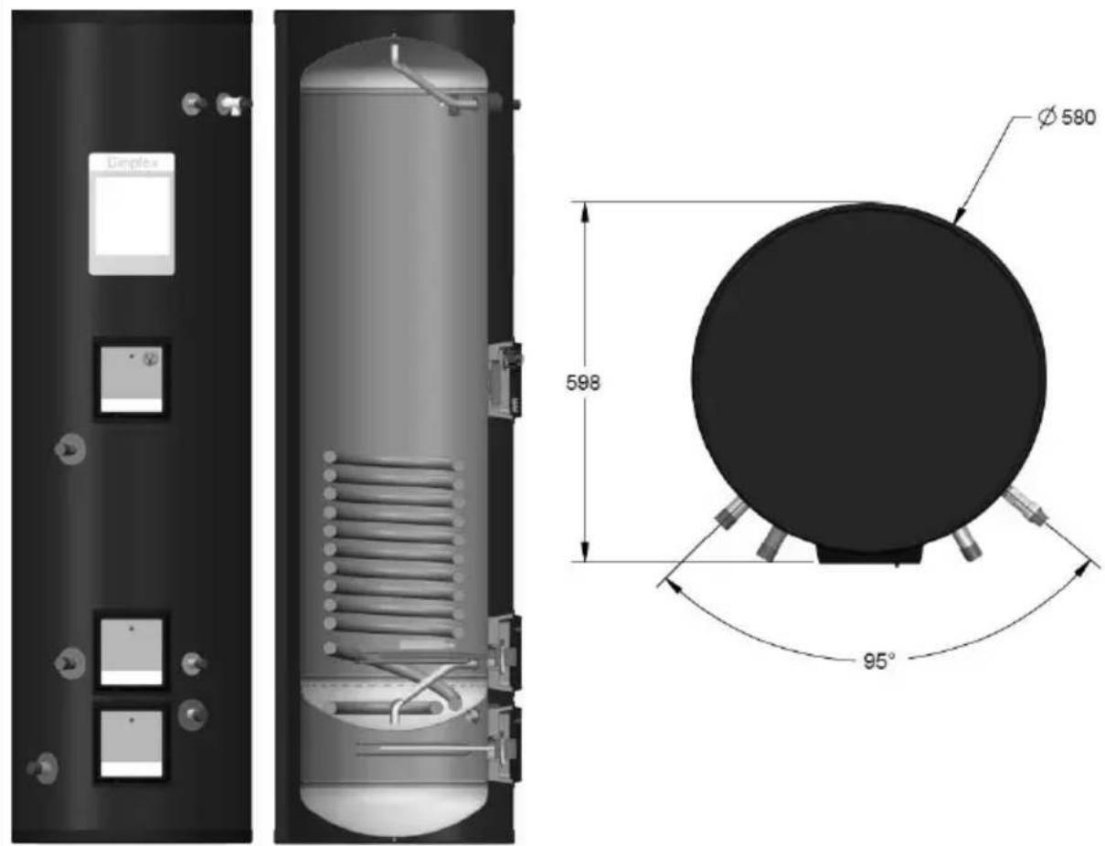
Figure 10: Heat Pump Buffer Cylinder and Cross-Section (For Reference Only)
| Heat Pump Buffer Cylinder Range - Dimensions | |
| Reference | ECS250HP40-580 |
| Capacity [l] | 245 |
| Hot Water Capacity [l] | 242 |
| Weight Empty [kg] | 66.5 |
| Weight Full [kg] | 316.5 |
| Reheat time [mins]* | 7.4 |
| Average draw off temperature [°C]* | 57 |
| Hot water draw off capacity (l)* / draw off flow rate (l/s) | 120 |
| 0.47 | |
| Heat loss [kWh/24h]* | 1.51 |
| Height [mm] | 2025 |
| Outer Diameter [mm] | 580 |
| HW Outlet [mm] | 1800 |
| T&P Valve [mm] | 1800 |
| Secondary Return [mm] | - |
| CW Inlet [mm] | 440 |
| Bottom Immersion [mm] | 240 |
| Top Immersion [mm] | 1145 |
| HP Buffer Flow/HP Flow to Buffer [mm] | 180 |
| HP Buffer Flow/Buffer Flow to HP [mm] | 312 |
| HP Return/DHW Return [mm] | 1147 |
| HP Flow/DHW Flow [mm] | 1667 |
| Bottom Thermostat [mm] | 500 |
Table 3: Heat Pump Buffer Cylinder Dimensions
Note: All measurements are taken from the base of the cylinder to the mid-point on the item. * Determined in accordance with EN12897 at 80°C flow temperature and 0.42l/s flow rate.
| GDC Group Ltd | Heat Pump Buffer Cylinder Range – Product Fiche |
| Reference | ECS250HP40-580 |
| Energy Rating | B |
| Standing Loss [W] | 66 |
| Storage Volume [L] | 245 |
| Heat Pump Buffer Cylinder Range - Product Features | |
| Materials- inner cylinder- outer cylinder- inlet/outlet- coils- insulation | Duplex stainless steel LDX2101HIPSStainless steelStainless steel60mm PU foam (GWP=1, ODP=0) |
| Maximum operating conditions- potable water temperature- heating water temperature- operating pressure | 70°C95°C3 bar |
| Cold water supply- minimum dynamic pressure- maximum pressure- minimum flow rate | 1.5 bar12 bar15 l/min |
| Connections- cold water inlet- hot water outlet- coil flow and return | 22mm stainless steel22mm stainless steel28mm stainless steel |
| Coil specification- heat pump coil surface area [m2]- HX performance heat pump coil [kW]- max. working pres. [Bar] | |
| 3.0 | |
| 47 | |
| 3 | |
| Immersion heater | 1 3/4 F BSP 3kW @ 240 V |
| Thermostatic control- direct input- indirect input | integral immersion heater thermostat and cut out integral twin thermostat (10 to 70°C) and cut out (~85°C) |
| Safety components- pressure reducing valve and strainer- expansion relief valve- temperature and pressure relief valve- factory pressure test | 3 bar6 bar1⁄2" 7 bar/90°C12 bar |
| Other features | Over 60% in volume from recycled materials#Surface mounted sensor devices for compatibility and ease of maintenance |
| Approvals | KIWA approval number:- 1309706 |
| Guarantee/Warranty- inner cylinder- immersion heaters- other components | 25 yrs2 yrs - excluding the effects of lime scale or other water borne contaminants2 yrs - excluding expansion vessel membrane pressure |
Table 4: Heat Pump Buffer Cylinder Product Fiche
Not including insulation
Table 5: Heat Pump Buffer Product Fiche and Features
9.1 Cylinder Heat Exchanger Pressure Drop
1.1 m² Coil Pressure Drop
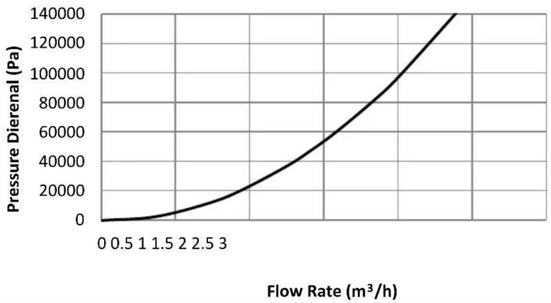
line
| Flow Rate (m³/h) | Pressure Dierenal (Pa) | | ---------------- | --------------------- | | 0 | 0 | | 0.5 | ~5000 | | 1 | ~10000 | | 1.5 | ~15000 | | 2 | ~25000 | | 2.5 | ~40000 | | 3 | ~60000 | | >3 | >140000 |2.2 m² Coil Pressure Drop
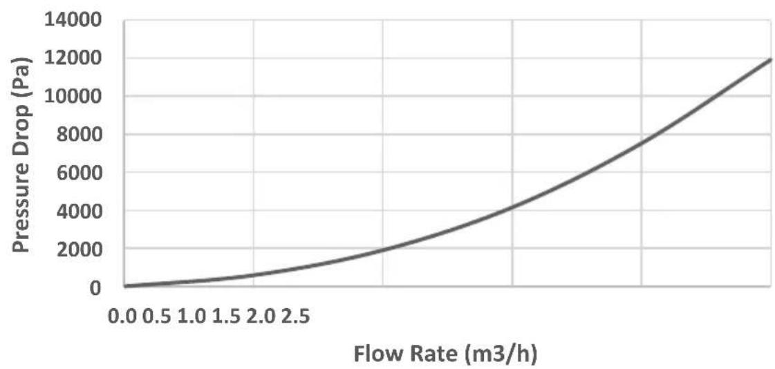
line
| Flow Rate (m3/h) | Pressure Drop (Pa) | | ---------------- | ------------------ | | 0.0 | 0 | | 0.5 | ~500 | | 1.0 | ~1000 | | 1.5 | ~1500 | | 2.0 | ~2500 | | 2.5 | ~4000 | | >2.5 | >12000 |Figure 11: Heat Exchanger Pressure Drops for 1.1m^2 and 2.2m^2 Coils
9.2 Cylinder Attainable Temperature Curves
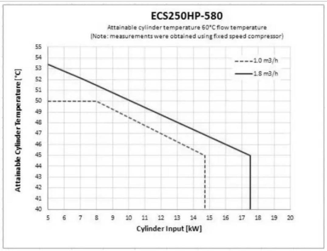
line
| Cylinder Input [kW] | 1.0 m3/h | 1.8 m3/h | | ------------------- | -------- | -------- | | 5 | 50 | 53 | | 8 | 50 | 51 | | 15 | 45 | 45 | | 17.5 | 40 | 40 |Figure 12: Cylinder Attainable Temperature Curves for ECS250HP-580
10 User Instructions
10.1 General
"This appliance can be used by children aged from 8 years and above and persons with reduced physical sensory or mental capabilities or lack of experience and knowledge if they have been given supervision or instruction concerning use of the appliance in a safe way and understanding the hazards involved. Children shall not play with the appliance. Cleaning and user maintenance shall not be made by children without supervision."
Please read the following statements carefully as it affects your warranty:
Please ensure that the installer has fully completed the Benchmark Checklist on the inside back pages of this document and that you have signed it to say that you have received a full and clear explanation of its operation. The installer is legally required to complete a commissioning checklist as a means of complying with the appropriate Building Regulations Part G3 (England and Wales), Part P of Northern Ireland and Section 6 of Scotland.
All installations must be notified to Local Area Building Control either directly or through a Competent Persons Scheme. A Building Regulations Compliance Certificate will then be issued to the customer who should, on receipt, write the Notification Number on the Benchmark Checklist.
This product should be serviced annually to optimise its safety, efficiency and performance. The service engineer should complete the relevant Service Record on the Benchmark Checklist after each service.
The Benchmark Checklist will be required in the event of any warranty work.
10.2 Operation
Once the system has been fully commissioned, no user intervention should be required to fully enjoy the comfort and benefits of the unvented hot water cylinder.
The hot water temperature can be set to various requirements. For operation with a heat pump it is recommended to set the hot water temperature to between 45°C and 55°C (this is between 2 and 3 on the dial, please refer to Figure 14 for approximate settings). Higher temperatures can cause tripping of the high limit thermostat, introduce more heat loss from the unit and increase the risk of scalding significantly.
When turning on a hot tap for the first time after a heat up period there might be a short surge of water. This is normal in unvented systems and does not constitute a fault. Sometimes the water may appear milky – this is due to very fine air bubbles in the water which will clear quickly.
10.2.1 Water Temperature Direct Electric Heating

Before removing the cover from the immersion heater isolate appliance using isolating switch! Danger of electrical shock! Only use suitable electrically insulated equipment when working inside immersion housing.
The hot water temperature achieved by the direct electric heating element can be adjusted by removing the cover from the immersion heater and adjusting the dial up or down as indicated in Figure 13.
Dial to adjust water temperature
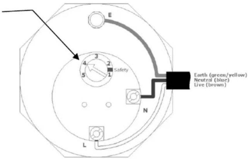
Figure 13: Adjustment Water Temperature Direct Electric Heating Element
10.2.2 Water Temperature Auxiliary Heating
The water temperature achieved by the auxiliary heating system depends on the setting of the thermostat on:
- the cylinder AND
- the auxiliary heating source
The adjustment at the cylinder is carried out on the twin thermostat
fitted to the cylinder as shown in Figure 14. In the event that the high temperature cut-out engages, it will be necessary to manually reset the thermostat. Use a suitable electrically insulated tool to push the manual reset button and inform the installer.
If the domestic hot water temperature is controlled by a sensor connected to the heat pump control unit, the thermostat on the cylinder should be turned to maximum to avoid any conflicting control signals.
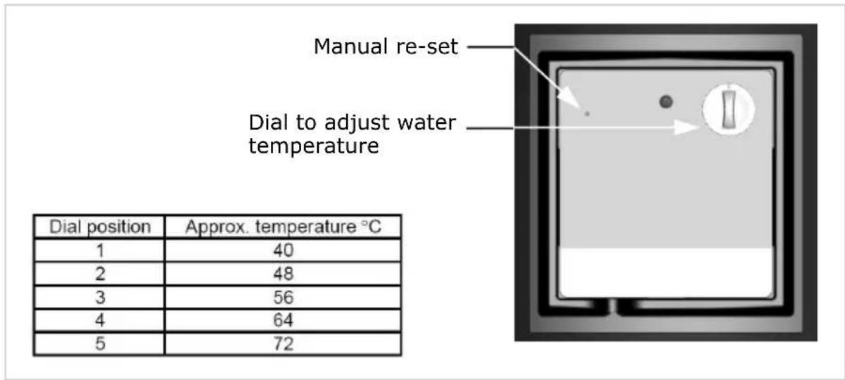
Figure 14: Adjustment Water Temperature Auxiliary Source
10.3 Maintenance

The maintenance of this appliance must be carried out by a suitably qualified person only. It is recommended to maintain the unit on an annual basis. Isolate all electrical supplies from the unit before commencing work. Danger of electrical shock! See section 7.
10.4 Troubleshooting
| Fault | Cause | Solution |
| A No water from hot water taps | A.1 Stop valve closedA.2 Strainer blockedA.3 Pressure reducing valve fitted against flow | A.1 Open stop valveA.2 Turn water supply off, clean strainer and re-commissionA.3 Re-fit with arrow showing in direction of flow |
| B No hot water | B.1 Timer/Programmer not set correctlyB.2 Auxiliary heating malfunctionB.3 Direct heating mal functionB.4 Auxiliary/direct heating high limit thermostat has tripped | B.1 Set timer/programmer correctlyB.2 Consult auxiliary heating system instructionsB.3 Call for qualified person to check immersion heaterB.4 Reset limit thermostat(s) and inform installer |
| C Intermittent water discharge through tundish on warm-up | C.1 Expansion vessel lost charge | C.1 Check expansion vessel (see commissioning /maintenance), top up or replace |
| D Continuous discharge | D.1 Pressure reducing valve not workingD.2 Pressure relief or T&P valve not seating correctlyD.3 Malfunction of high limit thermostat or appliance | D.1 Check pressure after valve and replace if faultyD.2 Manually lift valve once or twice to clear debris, otherwise replaceD.3 Check function of thermostats and appliances |
| E Leakage from casing | E.1 Compression/threaded joints not formed correctly | E.1 Re-seal joints with care |
| F Hot water from cold tap | F.1 Hot pipe work being routed adjacent to cold pipe workF.2 Leaking seal in mixer tap | F.1 Insulate hot pipe work or re-routeF.2 Replace seals in mixer tap |
| G Metallic noise from system | G.1 Pipe work not sufficiently supported | G.1 Add extra pipe work fixings |
| H Humming noise from system during re-heat | H.1 Air in systemH.2 Flow rate well in excess of specification | H.1 Bleed system thoroughly and re-pressurizeH.2 Reduce pump speed |
MAINS PRESSURE HOT WATER STORAGE SYSTEM COMMISSIONING CHECKLIST
This Commissioning Checklist is to be completed in full by the competent person who commissioned the storage system as a means of demonstrating compliance with the appropriate Building Regulations and then handed to the customer to keep for future reference.
Failure to install and commission this equipment to the manufacturer's Instructions may invalidate the warranty but does not affect statutory rights.
Customer Name Telephone Number
Address
Cylinder Make and Model
Cylinder Serial Number
Commissioned by (print name) ____ Registered Operative ID Number____
Company Name ____ Telephone Number ____
Company Address ____
Commissioning Date
To be completed by the customer on receipt of a Building Regulations Compliance Certificate*:
Building Regulations Notification Number (if applicable)
ALL SYSTEMS PRIMARY SETTINGS (Indirect heating only)
Is the primary circuit a sealed or open vented system? Sealed □ Open □
What is the maximum primary flow temperature?
ALL SYSTEMS
What is the incoming static cold water pressure at the inlet to the system? ____ bar
Has a strainer been cleaned of installation debris (if fitted)? Yes No
Is the installation in a hard water area (above 200ppm)? Yes No
If yes, has a water scale reducer been fitted? Yes No
What type of scale reducer has been fitted?
What is the hot water thermostat set temperature?
What is the maximum hot water flow rate at set thermostat temperature (measured at high flow outlet)? I/ml
Time and temperature controls have been fitted in compliance with Part L of the Building Regulations? Yes
Type of control system (if applicable) Y Plan □ S Plan □ Other □
Is the cylinder solar (or other renewable) compatible? Yes No
What is the hot water temperature at the nearest outlet? °C
All appropriate pipes have been insulated up to 1 metre or the point where they become concealed Yes □
Where is the pressure reducing valve situated (if fitted)?
What is the pressure reducing valve setting? bar
Has a combined temperature and pressure relief valve and expansion valve been fitted and discharge tested? Yes No
The landfill and discharge pipework have been connected and terminated to Part G of the Building Regulations Yes
Are all energy sources fitted with a cut out device? Yes □ No □
Has the expansion vessel or Internal air space been checked? Yes No
THERMAL STORES ONLY
What store temperature is achievable?
What is the maximum hot water temperature?
ALL INSTALLATIONS
The hot water system complies with the appropriate Building Regulations Yes
The system has been installed and commissioned in accordance with the manufacturer's instructions Yes
The system controls have been demonstrated to and understood by the customer Yes
The manufacturer's literature, Including Benchmark Checklist and Service Record, has been explained and left with the customer Yes
Commissioning Engineer's Signature
Customer's Signature
(To confirm satisfactory demonstration and receipt of manufacturer's literature)
*All Installations in England and Wales must be notified to Local Authority Building Control (LABC) either directly or through a Competent Persons Scheme, A Building Regulations Compliance Certificate will then be issued to the customer.
SERVICE RECORD
It is recommended that your hot water system is serviced regularly and that the appropriate Service Record is completed.
Service Provider
Before completing the appropriate Service Record below, please ensure you have carried out the service as described in the manufacturer's Instructions.
SERVICE 1 Date
Engineer Name
Company Name
Telephone Number
Comments
Signature
SERVICE 2 Date
Engineer Name
Company Name
Telephone Number
Comments
Signature
SERVICE 3 Date
Engineer Name
Company Name
Telephone Number
Comments
Signature
SERVICE 4 Date
Engineer Name
Company Name
Telephone Number
Comments
Signature
SERVICE 5 Date
Engineer Name
Company Name
Telephone Number
Comments
Signature
SERVICE 6 Date
Engineer Name
Company Name
Telephone Number
Comments
Signature
SERVICE 7 Date
Engineer Name
Company Name
Telephone Number
Comments
Signature
SERVICE 8 Date
Engineer Name
Company Name
Telephone Number
Comments
Signature
SERVICE 9 Date
Engineer Name
Company Name
Telephone Number
Comments
Signature
SERVICE 10 Date
Engineer Name
Company Name
Telephone Number
Comments
Signature
Dimplex a division of GDC Group Ltd
Millbrook House Grange Drive, Hedge End, Southampton SO30 2DF
Tel.: 0845 879 3588
Fax: 0845 879 3583
e-mail: customer.services@gdcgroup.co.uk
www.dimplex.co.uk
- Heat Pump Cylinders With Integrated 40l Buffer
- EC-Eau Cylinder Range
- Overall View
- Contents
- Technical Data and Product Fiche.... 30
- User Instructions.... 35
- CLEANING INSTRUCTIONS:
- Introduction
- Scope of Delivery
- Pre-Installation Advice
- Risk Assessment
- Siting Considerations
- - frost protection
- Cold Water Supply
- Building Regulation G3 Discharge Requirements
- Discharge Pipe D2
- Worked Example
- Termination of Discharge Pipe
- Limitations
- Installation
- Cold Water Inlet with Inlet Control Group
- Correctly Site the Cylinder
- Install the Inlet Group
- Expansion Vessel
- Balanced Cold Water Supply
- Drain Valve
- Hot Water Outlet
- Thermostatic Mixing Valve
- Pipe Insulation
- Discharge Pipes from Safety Devices
- Discharge Pipe D2
- Tundish
- Immersion Heater
- Coil Flow Connections
- Coil Return Connections
- HP Flow to Buffer
- Buffer Flow to HP
- Cylinder Thermostat & Heat Pump Sensor Connections
- Thermostat Connections
- Connection of the Sensor
- Connection of Secondary Return
- Heat Pump and Buffer Cylinder Schematic
- Commissioning
- Maintenance
- Spare Parts
- Technical Data and Product Fiche
- Not including insulation
- Cylinder Heat Exchanger Pressure Drop
- Cylinder Attainable Temperature Curves
- User Instructions
- General
- Please read the following statements carefully as it affects your warranty:
- Operation
- Water Temperature Direct Electric Heating
- Water Temperature Auxiliary Heating
- Maintenance
- MAINS PRESSURE HOT WATER STORAGE SYSTEM COMMISSIONING CHECKLIST
- ALL SYSTEMS PRIMARY SETTINGS (Indirect heating only)
- ALL SYSTEMS
- THERMAL STORES ONLY
- ALL INSTALLATIONS
- SERVICE RECORD
- Service Provider
- SERVICE 1 Date
- SERVICE 2 Date
- SERVICE 3 Date
- SERVICE 4 Date
- SERVICE 5 Date
- SERVICE 6 Date
- SERVICE 7 Date
- SERVICE 8 Date
- SERVICE 9 Date
- SERVICE 10 Date
- Dimplex a division of GDC Group Ltd
Brand : DIMPLEX
Model : ECS250HP40A-580
Category : Uncategorized