CEP500E - Heating Creda - Free user manual and instructions
Find the device manual for free CEP500E Creda in PDF.


| Product Type | Heater |
| Brand | Creda |
| Model | CEP500E |
| Power Source | Mains (220-240V, 50Hz) |
| Heating Power | 2000W |
| Heating Method | Fan heater / convection |
| Thermostat Control | Adjustable thermostat |
| Safety Features | Overheat protection, tip-over switch |
| Dimensions (W x D x H) | 25 x 20 x 30 cm |
| Weight | 2.5 kg |
| Color | White/Black |
| Heating Area | Up to 25 m² |
| Fan Speeds | 2 speeds (low/high) |
| Oscillation | Yes (automatic swing) |
| Remote Control | Yes (included) |
| Timer | 1-12 hours |
| Noise Level | Approx. 45 dB |
| Cleaning | Wipe with dry cloth, clean filter monthly |
| Repairability | Spare parts available (fan motor, thermostat) |
| Certifications | CE, RoHS |
Frequently Asked Questions - CEP500E Creda
User questions about CEP500E Creda
0 question about this device. Answer the ones you know or ask your own.
Ask a new question about this device
Download the instructions for your Heating in PDF format for free! Find your manual CEP500E - Creda and take your electronic device back in hand. On this page are published all the documents necessary for the use of your device. CEP500E by Creda.
USER MANUAL CEP500E Creda
Contour 100 Electronic Panel Heaters
INCMUKP7RG Issue 6
Dimensions
(millimetres)
Model(s) Watt A B
| CEP500E | 0.5kW | 503 | 104 |
| CEP750E | 0.75kW | 503 | 104 |
| CEP1000E | 1.0kW | 671 | 104 |
| CEP1500E | 1.5kW | 741 | 104 |
| CEP2000E | 2.0kW | 911 | 104 |
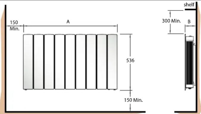
Fig. 1
IMPORTANT: THESE INSTRUCTIONS SHOULD BE READ CAREFULLY AND RETAINED FOR FUTURE REFERENCE
Important Safety Advice
When using electrical appliances, basic precautions should always be followed to reduce the risk of fire, electrical shock, and injury to persons, including the following:
IMPORTANT – The wall bracket supplied with the appliance must be used.
WARNING – DO NOT USE THIS HEATER IN THE IMMEDIATE SURROUNDINGS OF A BATH, A SHOWER OR A SWIMMING POOL.
IMPORTANT – If the heater is installed in a room containing a bath or shower, it must be so installed that switches and other controls cannot be touched by a person using a bath or shower.
Do not use outdoors.
Do not locate the heater immediately below a fixed socket outlet or connection box.
WARNING: In order to avoid overheating, do not cover the heater. Do not place material or garments on the heater, or obstruct the air circulation around the heater, for instance by curtains or furniture, as this could cause overheating and a fire risk.
NEVER cover or obstruct in any way the heat outlet slots at the top of the heater or the air inlet slots in the base of the heater.
The heater carries the Warning symbol indicating that it must not be covered.
CAUTION - Some parts of this product can become very hot and cause burns. Particular attention has to be given where children and vulnerable people are present. This appliance can be used by children aged from 8 years and above and by persons with reduced physical, sensory or mental capabilities or lack of experience and knowledge if they have been given supervision or instruction concerning use of the appliance in a safe way and understand
the hazards involved.
Children shall not play with the appliance. Cleaning and user maintenance shall not be made by children without supervision.
Children of less than 3 years should be kept away unless continuously supervised.
Children aged from 3 years and less than 8 years shall only switch on/off the appliance provided that it has been placed or installed in its intended normal operating position and they have been given supervision or instruction concerning use of the appliance in a safe way and understand the hazards involved. Children aged from 3 years and less than 8 years shall not plug in, regulate and clean the appliance or perform user maintenance.
Note that due care and consideration must be taken when using this heater in series with a thermal control, a program controller, a timer or any other device that switches on the heat automatically, since a fire risk exists when the heater is accidentally covered or displaced.
If the supply cord is damaged it must be replaced by the manufacturer or service agent or a similarly qualified person in order to avoid a hazard.
WARNING: Servicing and product repairs should only be undertaken by the manufacturers approved service agent or a similarly qualified person, using only exact manufacturer approved spare parts.
A means for disconnection must be incorporated in the fixed wiring of the premises in accordance with the wiring rules. The supply circuit to the heater must incorporate a double pole isolating switch having a contact separation of at least 3mm.
Electrical
WARNING – THIS APPLIANCE MUST BE EARTHED
The electrical installation must be carried out by a competent electrician, and be in strict accordance with the current I.E.E. regulations for Electrical Equipment in Buildings.
The wires in this mains lead are coloured in accordance with the following code:
GREEN AND YELLOW : EARTH
| BLUE | : | NEUTRAL | |
| BROWN | : | LIVE | |
| BLACK : | PILOT WIRE | ||
- see also 'Pilot Wire Connection'.
The heater is fitted with a length of flexible cable type H05VV-F size 4 x 1.0mm² for connection to the fixed wiring of the premises through a suitable connection box positioned adjacent to the heater.
The supply circuit to the heater must incorporate a double pole isolating switch having a contact separation of at least 3mm.
Pilot Wire Connection
The BLACK control wire is designed to carry a signal from slot in or wall mounted Creda programmers. If, however a programmer is not being used, the pilot wire should be isolated in accordance with the current IEE Wiring Regulations.
IMPORTANT - DO NOT connect the BLACK pilot wire to earth. Care should be taken with the installation of the pilot wire(s) as when switching to background (set back) they become energised at 240V although only at a current of less than 100mA. In every case a suitable means of isolation must be provided for the pilot wire and marked to indicate that two sources of supply may be present at the heater. Where pilot wires are installed separately from the heater final sub-circuit they should be protected, double insulated and carry their own integral earth continuity conductor.
Supplementary Earth Bonding
Should Equipotential Earth Bonding be required the earthing conductor in the supply cord is deemed to provide the supplementary bonding connection (see Regulation 544.2.5, 17 ^th Edition I.E.E. Wiring Regulations).
General
The heater is designed for wall mounting on the wall bracket supplied. It should only be operated when in the upright position as shown - see Fig. 1.
All models are splashproof to IPX4 standard and may be used in bathrooms, however not in the immediate vicinity of baths, showers, water connections, wash basins or swimming pools.
Before connecting the heater check that the supply voltage is the same as that stated on the heater.
NOTE - Lit cigarettes, candles and oil burners, combined with the convection effect of electric heaters can cause soot deposits to build up on the surface directly above and to the sides of the heater. This is not a fault of the heater. Extensive burning of candles or smoking in the operating environment of this product can produce heavy discolouration within a few months of use.
Wall Mounting
IMPORTANT – The wall bracket supplied with the appliance must be used. The heater should be positioned observing the minimum clearances stated around the heater - see Fig. 1 and Fig. 2.
DO NOT locate the heater immediately below a fixed socket outlet or connection box.
- Remove wall mounting bracket from the back of the heater by depressing the spring latch at the top of each bracket - see Fig. 2.
- Fix the wall bracket securely to the wall through the four screw holes provided.
- Present the heater to the wall bracket, and engage lower slots in the back with bracket.
- Raise the heater to upright position and push the heater onto the bracket to engage the top latch.
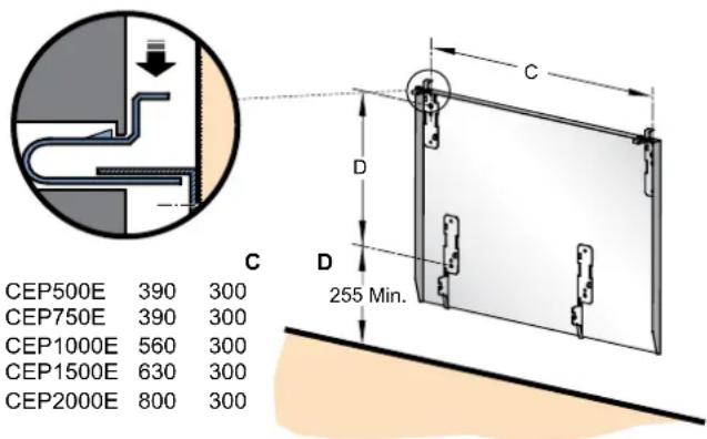
Fig. 2
Operation
Switching On the Heater
The controls are located on the right hand side on top of the appliance.
The button marked ⏻ controls the electricity supply to the electronic thermostat. An indicator beside the ⏻ button shows when the unit is powered 'ON'.
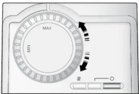
Fig. 3
Setting Desired Temperature (see Fig. 3)
The heater is fitted with an adjustable thermostat enabling the room temperature to be controlled by rotating the knob accordingly. The min setting represents a room temperature of approximately 5 °C and may be used for protection against frost. The 'MAX' setting represents a room temperature of approximately 30°C. The 'Symbol glows when the elements are actually heating.
Turn on the heater using the button and rotate the thermostat knob to the desired position. When the room temperature has reached the desired level, the power to the elements will be reduced, the heater will then maintain the room temperature at the chosen level.
NOTE - Should your heater fail to come on when the thermostat knob is at a low setting, this may be due to the room temperature being higher than the thermostat setting.
Background Temperature
When used in conjunction with a remote programming device supporting a background/setback setting, the heater will automatically operate at a room temperature setting of 5^ C less than the thermostat setting when the programme is in background/setback mode.
Limiting the thermostat setting
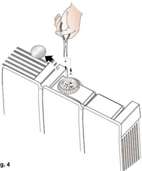
Before wall mounting the product the installer may wish to limit the heat selection knob movement for the operator. This may be achieved by unclipping the knob and removing the two plastic pins (see Fig. 4) using pliers and inserting them in the preferred holes to limit the knob movement. Replace the plastic cap.
natural_image
Illustration of a hand using a tool to lift a ball from a tray, with no visible text or symbols.Fig. 4
Notes to the Installer
Test Mode
When the heater is connected via a pilot wire system, the test mode allows the installer to check whether the heater is responding correctly to the incoming pilot wire signal.
Before switching the heater on at the mains, rotate the thermostat knob to the 'MAX' position, then press and hold the ⏻ button whilst switching on the mains.
The unit will now enter a test state for 4 mins. During this test state the ☑ neon will indicate the pilot wire status:
NEON PILOT WIRE CONTROLLER MODE
Neon on - ON
Neon off - OFF
Neon flashing fast approx every 0.1sec - FROST
Neon flashing slow approx every 0.5 sec - SETBACK
Accessory Modules
Optional accessory modules are available for use with this range of heaters - see separate User Instructions for details on the operation of each accessory module.
Before fitting a control module switch the heater off at the mains supply.
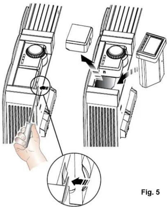
To insert a module, the plug-in protective cover on the right hand side of the thermostat unit at the back of the heater must first be removed.
Insert a flat-head screwdriver into the side of the cover and prise away from the heater - see Fig. 5.
Lift the cover away from the heater to reveal the slide in compartment. Insert the accessory module into the slot ensuring it is positively located in position - see Fig. 5. Secure the module in place with the screw provided.
Switch the heater on at the mains supply.
Safety - Overheat protection
For your safety this appliance is fitted with a thermal cut-out. In the event that the product overheats for some reason, the cut-out prevents excessive temperatures on the product by cutting the power to the heater. Once the heater has cooled down, it will reset automatically, it will continue to cycle on and off automatically until the reason for overheating is removed.
Cleaning
WARNING – ALWAYS DISCONNECT FROM THE POWER SUPPLY BEFORE CLEANING THE HEATER.
Before commencing cleaning, unplug the heater and allow it to cool. Disconnect the electricity supply to the appliance.
The outside can be cleaned by wiping it over with a soft damp cloth and then dried. Do not use abrasive cleaning powders or furniture polish, as this can damage the surface finish.
To release the heater from the wall bracket for cleaning or redec- oration, depress the latch on each bracket (see Fig. 2) and hinge forward.
Recycling
For electrical products sold within the European Community. At the end of the electrical products useful life it should not be disposed of with household waste. Please recycle where facilities exist. Check with your Local Authority or retailer for recycling
advice in your country.
After Sales Service
Your product is guaranteed for one year from the date of purchase. Within this period, we undertake to repair or exchange this product free of charge provided it has been installed and operated in accordance with these instructions. Your rights under this guarantee are additional to your statutory rights, which in turn are not affected by this guarantee.
Should you require after sales service you should contact our customer services help desk on 0844 879 3588. It would assist us if you can quote the model number, series, date of purchase, and nature of the fault at the time of your call. The customer services help desk will also be able to advise you should you need to purchase any spares.
Please do not return a faulty product to us in the first instance as this may result in loss or damage and delay in providing you with a satisfactory service. Please retain your receipt as proof of purchase.
Energy Saving Tips
The energy we use to heat, light and power our homes contributes over a quarter of the UK's carbon emissions, the principle contributor to climate change.
Around half the energy used in the home is for heating and hot water, so using your heating system efficiently will not only help the environment, but also save you money!
Energy efficiency tips for heating and hot water
1. Don't set the temperature too high...
By reducing the thermostat setting by just 1^ can reduce your energy use by as much as 10% . And if you're going away for the winter, leave the thermostat on the frost protection setting to provide protection from freezing at a minimum cost.
2. Use it where you need it...
Set the appropriate temperature on your heaters for the room they are in; for example, leave the thermostat on a heater in a spare bedroom on a lower setting.
3. Use it when you need it...
Use heaters fitted with timers or linked to central controllers to turn the heating on only when you need it and automatically switch it off when you don't.
4. Curtains...
Close your curtains at dusk to stop heat escaping through the windows.
5. Windows...
Nearly 25% of heat loss can occur through poorly insulated frames and single glazing. If you can't afford to double glaze all your windows, go for the rooms you heat most.
6. Treat your hot water tank... give it a jacket
An insulating jacket for hot water tanks only costs a few pounds and pays for itself within months. Fit one that's at least 75mm (3") thick and you could save £10-£15 a year.
7. Water...
Use a shower if you have one to save time, money and water.
Don't set the thermostat too high on your water heater - 60°C/140°F is usually adequate for bathing and washing.
Put the plug in when running hot water in your sink - leaving hot taps running is both wasteful and expensive.
Ensure dripping taps are repaired quickly. In just one day, you could waste enough water to fill a bath.
Other Energy Saving Tips for Around the Home
1. Lights
Turn off lights whenever you leave a room for more than ten minutes.
Use low-energy bulbs wherever you can as they use less than a quarter of the electricity used by ordinary light bulbs and last ten times longer!
2. Cooking
Use the right size pan for the food and cooker hob.
Keep saucepan lids on - this enables you to turn down the heat.
Boil water for cooking in a kettle.

The product complies with the European Safety Standards EN60335-2-30 and the European Standard Electromagnetic Compatibility (EMC) EN55014, EN60555-2 and EN60555-3. These cover the essential requirements of EEC Directives 2006/95/EC and 2004/108/EC

CREDA HEATING
MILLBROOK HOUSE
GRANGE DRIVE
HEDGE END
SOUTHAMPTON
SO30 2DF
TEL: 0844 879 3588
WEBSITE: www.credaheating.co.uk
EMAIL: customer.services@credaeheating.co.uk
Republic of Ireland Tel: 01 842 8222
- Contour 100 Electronic Panel Heaters
- Important Safety Advice
- WARNING – DO NOT USE THIS HEATER IN THE IMMEDIATE SURROUNDINGS OF A BATH, A SHOWER OR A SWIMMING POOL.
- Electrical
- WARNING – THIS APPLIANCE MUST BE EARTHED
- Pilot Wire Connection
- Supplementary Earth Bonding
- General
- Wall Mounting
- Operation
- Switching On the Heater
- Setting Desired Temperature (see Fig. 3)
- Background Temperature
- Limiting the thermostat setting
- Notes to the Installer
- Test Mode
- NEON PILOT WIRE CONTROLLER MODE
- Accessory Modules
- Safety - Overheat protection
- Cleaning
- WARNING – ALWAYS DISCONNECT FROM THE POWER SUPPLY BEFORE CLEANING THE HEATER.
- Recycling
- After Sales Service
- Energy Saving Tips
- Energy efficiency tips for heating and hot water
- Don't set the temperature too high...
- Use it where you need it...
- Use it when you need it...
- Curtains...
- Windows...
- Treat your hot water tank... give it a jacket
- Water...
- Other Energy Saving Tips for Around the Home
- Lights
- Cooking
Brand : Creda
Model : CEP500E
Category : Heating