Exit Device Operators 630 - Emergency Output System Dormakaba - Free user manual and instructions
Find the device manual for free Exit Device Operators 630 Dormakaba in PDF.


| Product Type | Exit Device Operator (Electronic Lock) |
| Brand | Dormakaba |
| Model Series | 630 / 730 / 750 / 79E / E7900 |
| Compatible Exit Devices | Dorma 9100/9300/9400/9500, F9100/F9300/F9400/F9500, Detex F10, Precision21/22/FL21/FL22, Arrow, Von Duprin, Yale |
| Power Source | 3 AA batteries (included) |
| Battery Voltage | 4.5 V (3 × 1.5 V) |
| Access Methods | Keycard (magnetic stripe), code entry (630 series via Oracode), mechanical key override |
| Programming | FDU (Front Desk Unit), ATLAS M-Unit, Oracode Maintenance Unit, command cards |
| Handing | Field reversible (left/right) |
| Lever Handle | Horizontal rest position, rotates approx. 45° |
| Spindle | Adjustable length for door thickness |
| Compliance | UL classified for fire exit hardware, FCC Part 15, ICES-003 |
| Override Options | Electronic override via FDU, mechanical key override |
| Locking Mechanism | Electronic with mechanical override |
| Installation | Professional installation required; drilling template provided |
| Tools Required | Safety glasses, drill, drill bits (5/16", 1/2", 1"), screwdrivers, Allen key, rubber mallet |
| Maintenance | Replace batteries when voltage <4V; clean with damp cloth; avoid harsh chemicals |
| Spare Parts | Lever handle, cylinder, battery holder, adaptor plate, spindle, screws, caps |
| Warranty | Standard dormakaba warranty (damage from improper installation not covered) |
| User Manual | Available for free download in PDF format (22 pages, EN) |
Frequently Asked Questions - Exit Device Operators 630 Dormakaba
User questions about Exit Device Operators 630 Dormakaba
0 question about this device. Answer the ones you know or ask your own.
Ask a new question about this device
Download the instructions for your Emergency Output System in PDF format for free! Find your manual Exit Device Operators 630 - Dormakaba and take your electronic device back in hand. On this page are published all the documents necessary for the use of your device. Exit Device Operators 630 by Dormakaba.
USER MANUAL Exit Device Operators 630 Dormakaba
natural_image
Close-up of a metallic door key with a digital keypad and handle (no visible text or symbols)630 Series

natural_image
Metal door handle with a scroll wheel and handle, no visible text or symbols750 Series

natural_image
Close-up of a silver-colored digital door with a black handle and green key (no text or symbols visible)79E/RT/E7900 Series

natural_image
Metallic hand door with handle and screen, no visible text or symbolsE-730 Series

natural_image
Metal emergency exit handle with handle, no visible text or symbolsExit Device Operators 630/750/79E/RT/E7900 Series/ Generation E-730
Installation instructions
PK3677-T - 2018 - 09
EN
dormakaba
Table of contents
A- Checklist and Exploded Views 3
B- Introduction and Disclaimers 4
C- Prepare the Door For the Appropriate Exit Device 4
D- Install the Lock and the Exit Device 5
- Install the Mortise 5
- Install the Outside Lever on the Outside Housing 5
- Install the Battery Holder 5
-
Install the Lock and Exit Device on the door 6
-
Install the lock and Exit Device with Messenger/Bluetooth on the door. 7
E- Test the Operation of the E-730 / 750 / 79E Lock 8
F- Program the E-730 / 750 / 79E Lock 9
G- Operating the Emergency Override 10
H- Test the operation of the 630 Lock 11
J- Installing the Mechanical Override 12
Parts and Tools List 12
- Upon unpacking the Lock 13
- Preparing the Outside Housing for the Installation of the Lever 13
- Preparing the Lever Handle and Cylinder for Installation 14
- Steps to attach the Lever Handle to the Lock Housing 14
-
Attaching the Lever Handle to the Lock 15
-
Verify the Attachment of the Lever Handle 16
- Test the Movement of the Lever Handle 16
-
Test the Mechanical Override Function 17
-
Cover the Keyhole and Cylinder with Cap 17
-
How to Change Lock Cylinders 17
A Checklist

** Dorma 9100/9300/9400/9500 Series are Panic Hardware only (not fire rated)
Dorma F9100/F9300/F9400/F9500 Series are Fire Rated Hardware
Each lockset for E-730/630/750/79E/E7900 includes:
(A) Outside lever handle
(B) Outside housing
(C) Gasket (when required)
(G) Exit Device (Included if ordered with lock operator)
(J) Battery holder with 3 AA batteries
Parts inside hardware bag:
(D) 1 x Spindle except for the following Exit Device which have 3: Detex F10, Dorma F9300 and Precision21/22/FL21/FL22
(E) 1 x Inside Adaptor Plate
(F) 3 x Mounting Screw 12-24 1/8" Hex
(H) 2 x Pan Head Screws 1/4" 28 X 3/4" for Yale
2 or 4 Pan Head Screws 10-24 X 3/4" for Detex,
Dorma, Von Duprin or 4 Flat Head screw 10-24 X
5/8" for Precision, Arrow
(K) 1 x Spanner-head Screw
(Q) 2 or 4 Flat Washer 12 OD for Detex Exit Device Only
Messenger / BLE Generation includes:
(S) Double enclosure.
(T) 2 X Pan Head Screws 8-32 X 1/2"
Mechanical Override Models ONLY:
(L) Cylinder Cap
(M) Cylinder Plug
(N) Outside Lever Handle
(O1) Adapter
(O2) Adapter & Screw
(P) Cylinder (for 630 series lock with cylinders keyed different ONLY)
E7900 Messeger/BLE Generation includes:
(S) Battery/Antenna enclosure with spacer.
(T1) 2x Flat Head Screws 8-32 X ^3/4
(T2) 2x Flat Head Screws 8-32 X 1 ^1/8 "
(P) Cylinder (for 630 series lock with cylinders keyed different ONLY)
Tools Required:
Safety glasses
5/16" (7.9mm) drill bit
1/2'' (13mm) drill bit
1" (25mm) drill bit
Drill
Awl or center punch
Hammer
Rubber mallet
Small flat screwdriver
Philips #2 screwdriver
Spanner screwdriver (No 6)
1/8" Allen key
Adjustable square
Tape measure
Pencil
Tape
Cleaning supplies
(drop cloth, vacuum)
B Introduction and disclaimers
IMPORTANT
Please read and follow all directions carefully. These instructions are designed for use by maintenance professionals or lock installers who are familiar with common safety practices and competent to perform the steps described. dormakaba. is not responsible for damage or malfunction due to incorrect installation, that may arise.

WARNING
Carefully inspect windows, doorframe, door, etc. to ensure that the recommended procedures will not cause damage. dormakaba standard warranty does not cover damages caused by installation.

CAUTION
Wear safety glasses when making the holes.
C Prepare the door for the appropriate exit device
1) Choose from the DT kit the drilling template of the lock for the exit device to be assembled on the door.
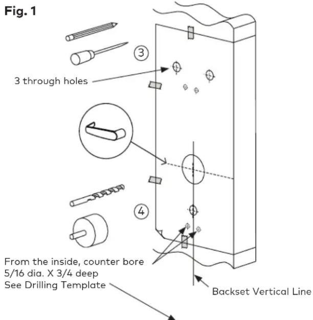
2) Mark the desired handle height on the edge of the door. (see Fig.1)
3) Mark the backset vertical line on each side of the door. Consult the exit device manufacturer's instructions for the correct backset. The backset shown on the paper template is for reference only. use exit device backset.
IMPORTANT
Respect all applicable building codes regarding the handle height of the lock and positioning of the bar.
4) Position the drilling template (attached in this booklet) on the inside of the door aligning the door handle height mark and backset vertical line mark with the lines on the template. Mark the door for the holes position.
5) Drill holes to diameters specified on the drilling templates.
Drill the holes in the door required for the exit device according to the manufacturer's instructions.
IMPORTANT
Drill from both sides of the door to prevent unsightly damage. Refer to template for drill size and depths

D Install the lock and the exit device
1 Install the Mortise (if applicable)
For mortise exit devices, install the mortise according to the manufacturer's instructions.
2 Install the Outside Lever

natural_image
Line drawing of a door handle with a cylindrical component inserted, showing an arrow indicating direction (no text or symbols)A Assemble the lever on the outside housing, in the horizontal rest position appropriate to the handing of the door as shown. Simply push the lever onto the tube until it clicks in place. If more force is required to engage the handle, use a rubber mallet. Test the attachment of the handle by pulling smartly on it.

B The lever is field reversible. If the handing is incorrect, insert a small pick or flat screwdriver in the hole in the hub as shown. Gently pry back the spring clip inside the hub, and remove the handle.

natural_image
Technical line drawing of a door handle with adjustment knob and scroll wheel (no text or symbols)
* For Mechanical Override Models refer to page 12.
3 Install the Batteries
Three AA batteries should already be installed in the battery holder (J). Insert the battery holder into the outside housing and secure it using the 6-32 X 3/8" spanner drive screw (K).
For de E7900 series lock, insert the 4 AA batteries into the battery holder (J). Insert the battery holder into the enclosure and secure it using the supplied screw (K).
IMPORTANT
If the lock makes a continuous buzzing noise or the red LED lights continuously, reset the electronics by removing the battery holder for ten seconds, then reinsert it.

D Install the lock and the exit device
4 Install Lock & Exit Device on the door
Fig. 3

4.1 Insert the slotted end of the spindle (D) into the outside housing until it locks, at the correct position for the exit device (see the document named "spindle position"). The spindle can be removed by pulling on it, and re-inserted if oriented incorrectly. Choose a spindle that engages by 1/8" minimum in the exit device chassis and that it is not too long to bottom-out against the exit device mechanism to jam the lock assembly, once it is tightened down.
4.2 Place the outside housing (B) on the door. (with gasket (C) if required)
4.3 Attach Adaptor Plate (E) to the lock (B) using 3 Flat Head screw (F)(12-24nc).
4.4 Attach the Exit Device chassis (G) to the Adaptor Plate (E) using 2 screws or 4 screws (H) depending on the Exit Device. For Detex only, use 2 or 4 Flat washers (Q).
4.5 Make sure the lock and the Exit Device are well aligned and then tighten screws.
4.6 Follow the manufacturer's instructions to complete the installation of the exit device and the appropriate strike.
D Install the lock and the exit device (Continued)
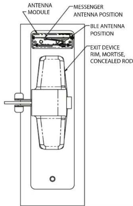
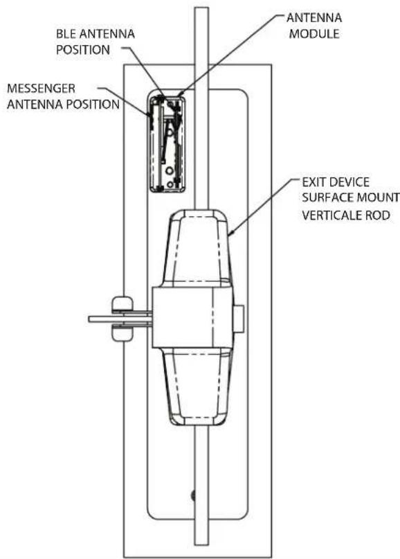
5 Install Lock & Exit Device with Messenger/Bluetooth or E7900 on the door

5.1 Insert the slotted end of the spindle (D) into the outside housing until it locks, at the correct position for the exit device (see the document named "spindle position"). The spindle can be removed by pulling on it, and re-inserted if oriented incorrectly. Choose a spindle that engages by 18 minimum in the exit device chassis and that it is not too long to bottom-out against the exit device mechanism to jam the lock assembly, once it is tightened down.
5.2 Pass wires (W) through the gasket (C) and the hole (H3). For the hollow doors, the wires shall pass inside the door to come out from the hole (H2).
5.3 Place the outside housing (B) on the door. (with gasket (C) if required)
5.4 Attach adaptor plate (E) to the lock (B) using 3 flat head screw (F) (12-24unc) (for solid doors, make sure that the wires are in the slot (S1)).
5.5 Attach the Exit Device chassis (G) to the Adaptor Plate (E) using 2 screws or 4 screws (H) depending on the Exit Device. For Detex only, use 2 or 4 Flat washers (Q)
5.6 Make sure the lock and the Exit Device are well aligned and then tighten screws.
5.7 Connect wires (W) to corresponding connectors and put the excess cables and connectors in the hole (H2) on the door.
5.8 Install S-support with screws T in the adaptor plate
5.9 Put the cover s-cover as shown on fig.5, and put the screw s-screw.
5.10 Follow the manufacturer's instructions to complete the installation of the exit device and the appropriate strike.
D Install the lock and the exit device (Continued)
5 Install Lock & Exit Device with Messenger/Bluetooth on the door (continued)
E Test the operation of the E-730/750/79E lock
(for 630 lock go to Section H) (For RT lock series, please refer to system 6000 manual)

CAUTION
Perform the following procedures in order, with the door OPEN unless otherwise indicated.
1 Panic Bar
Activate the panic bar. The latch bolt or rod retracts fully.
2 Outside Lever
Turn the outside lever downward. The latch bolt or rod does not retract.
If the latch bolt or rod retracts, verify that the batteries are properly installed.
If the lever feels tight (hard to turn, or does not return easily to its horizontal rest position), check the spindle length vs. the door thickness (the spindle may be too long). Check that the slotted end of the spindle is inserted in the lock housing hub, not the exit device.
3 Electronics and Card Reader
Test the lock's response to keycards: a Test keycard, a Grand Master keycard, and an Emergency keycard.
Insert keycards as shown below, with the magnetic stripe facing toward the door and to the left. For 79E, present cards to reader.
A Test the Lock Before Programming
Normal Entry: Use the Test keycard with the reader. The red and green LEDs each flash once and then the green LED flashes for four seconds.
Turn the outside lever downward while the green LED is flashing. The latch or rod retracts fully. Release the lever, then turn it again. The latch or rod must not retract after the LED stops flashing without first inserting the keycard.
B Lock Programming
Program the lock with its Common Area number (exit devices are usually programmed as common areas, see Reference Manual).
Use the Grand Master keycard with the reader. The green LED flashes. Turn the outside lever downward while the green LED is flashing. The latch or rod retracts fully and the LED stops flashing after 4 seconds. Release the lever, then turn it again. The latch or rod must not retract again without first inserting the keycard.
C Emergency Keycard Access
Use the Emergency keycard with the reader. The green LED flashes for 4 seconds. Then, turn the outside lever downward. The latch or rod retracts fully.

While standing outside the room, close the door and ensure that it is properly latched. Open the door using the Grand Master keycard using the same procedure.
F Program the E-730/750/79E/E7900 lock
(For 630 lock go to Section H) (For RT lock series, please refer to system 6000 manual) (E7900 see command card)
FDU
Program the lock using the FDU and the E-760/770/790 communication cable (see Reference Manual). If this is not a new installation but a replacement of a single lock or a group of locks in a property already equipped with the dormakaba locking system, transfer the security information from a neighbouring lock to the new lock by using the Reset Addresses function (see Reference Manual resetting lock addresses).
ATLAS
Program the lock using the M-Unit (Maintenance Unit). Refer to ATLAS User Guide.
In the case of a replacement lock resetting the addresses will ensure that all past lost and stolen keycards remain cancelled in the new lock and will set the addresses for the Section, Floor, Group, Zone and Area sub-master level so that staff keycards in use at the property will have the same pattern of access to the door as before. This step makes the lock replacement transparent so that the new lock accepts and rejects the same keycards as the old lock.
Multihousing
Program the lock using the M-unit or EAMU FDU. Refer to RezShield User Guide or FDU user Guide.
Aurora
Program the lock using the M-unit (Maintenance Unit) or with command cards and Aurora software using the Aurora software guide.
Enterprise
Program the lock using the PC M-unit (Maintenance Unit) or with command cards and Enterprise software using the Enterprise software guide.
G Operating the emergency override For RT lock series, please refer to system 6000 manual. For multihousing refer to RezShield manual.
CAUTION
If the lock will not respond to any keycard (including the Emergency keycard), there are four options that should be attempted to open the door. In order, they are:
- Verify the batteries, and replace them if they are providing less than 4 Volts total. Use the Emergency keycard.
- Use the electronic override feature (requires FDU and communication cable or ATLAS M-Unit and IPM).
- Use mechanical key if locking system has one (see Section J, step 8).
- Contact Technical Support for instructions on using the drill point.
Electronic override using the FDU:
(For electronic override using ATLAS, please refer to ATLAS user guide)
If the card reader fails, the E-730/630/750/79E lock can be opened using the FDU (Front Desk Unit). The lock must have been initialized by a valid FDU from the hotel where it is installed (i.e. with the correct internal and external hotel codes), before the electronic override can be used.
There are two possible security levels:
Low security: IF an FDU with a software version lower than V2.01 overrides the lock, the lock audit records only the date and time.
High security: IF an FDU with version V2.01 or higher software overrides the lock, the lock audit records the FDU number, the Authorization key-card number, the date and the time.
Hardware Required:
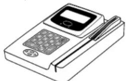
Front Desk Unit (FDU) and Communication Cable
natural_image
Line drawing of a handheld electronic device with a screen and pen (no text or symbols)Minimum Authorization Keycard Required:
Programming Authorization (PA)
Lteps to activate the E-730/630/750/79E electronic override:
- Insert the communication cable into the lock. Wait 2 seconds, then connect the cable to the serial port of the FDU.
IMPORTANT
Some messages on the screen may differ depending on the FDU version, but the menu choices are the same.
- Press any key to activate the FDU, then swipe a PA or higher keycard through the FDU. If the green LED on the lock flashes once, disconnect the cable from the Serial Port, wait 2 seconds, and reconnect the cable.
$$ \begin{array}{l} \text { Main Menu: } \ 1 = \text { K e y c a r d } \ 2 = \text { Reset } \ ? \ \end{array} $$
- Enter 8 to select the Programming Menu, then press <.
$$ \begin{array}{l} \text { Program } \ 1 = A \text { lock } \ 2 = \text { Another FDU } \ ? \ \end{array} $$
- Wait 2 seconds. Enter 1 to select the Lock option, and press <=>.
$$ \begin{array}{l} \text { Enter Function } \ 1 = \text { Program Addresses } \ 2 = \text { Reset Addresses } \ ? \ \end{array} $$
- Enter 7 to select the Override option, then press <→.
Ready to perform anelectrical override.
Strike a key, or C to quit
- Wait 2 seconds, then press any key on the FDU to activate the electronic override. The green LED on the lock should light. The following message should appear on the FDU screen immediately or within 2 seconds.
Trying to establish communication
G Operating the emergency override For RT lock series, please refer to system 6000 manual. For multihousing refer to RezShield manual. (Continued)
Communication Successful Press any key to continue
- Open the door. You have only 4 seconds after this message appears to open the door.
- Remove the communication cable from the lock.
H Test the operation of the 630 lock
(For 730/750/79E lock go to Section E)

CAUTION
If the lock will not respond to any keycard (including the Emergency keycard), there are four options that should be attempted to open the door. In order, they are:
1 Panic Bar
Activate the panic bar. The latch bolt or rod retracts fully.
2 Outside Lever
Turn the outside lever downward. The latch bolt or rod does not retract.
If the latch bolt or rod retracts, verify that the batteries are properly installed.
If the lever feels tight (hard to turn, or does not return easily to its horizontal rest position), check the spindle length vs. the door thickness (the spindle may be too long). Check that the slotted end of the spindle is inserted in the lock housing hub, not the exit device.
3 Electronic
A Programming
Program the lock with at least one user, using the Oracode Maintenance Unit. Generate a valid code for this user. (Recommendation: generate a code that starts a day before today and finishes at least one day after installation/testing date, in order to avoid check-in/check-out time periods)
B Code entry and access
Enter the user code to validate complete lock operation. Verify that the green LED flashes at each key pressed and a longer green LED flashes at the end of the code entry. Turn the outside lever. Make sure the latch bolt retracts fully. Release the lever, wait for the lock to return to the locked mode (default settings is 5 seconds after unlocking), and then turn the lever again. The latch bolt must not retract after the lock has returned to locked mode, which is typically 5 seconds (max 15 sec.) after unlocking, without first entering a valid user code.
J Installation of the mechanical override
Parts and Tools List
Tools Required:

Diagram of lock:
(A) Lock housing
(B) Inside drive hub
(C) Nylon washer
(D) Spring washer (Not for lever feel)
(E) Drive tube
(F) Lever catch
(G) Countersink
(H) Lever handle
(I) Cap
(J) Cylinder
(K) Cylinder plug
(L) Override shaft
(K1) Set Screw
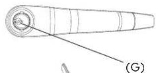
(A)

Facing view of drive tube: (E)

1 Upon unpacking, the lock housing with mechanical override should look like the diagram below with:
(A) The small indents on the cross of the override shaft in line horizontally
(B) The nylon washer and the spring washer (not for lever feel) on the drive tube
(C) The lever catch in the out position
(D) Cylinder and 2 keys for 630 K/C included in the hardware bag


natural_image
Technical line drawing of a mechanical component with a curved base and circular end (no text or symbols)
CAUTION
Assemble the lever, cylinder and lock components before affixing the entire unit to the door.

natural_image
Technical line drawing of two cylindrical electronic devices with mounting holes (no text or symbols)2 Preparing the outside housing for the installation of the lever handle
- Insert the cylinder (D) or equivalent tool into 2. Push in the lever catch firmly. (see Fig. 2) the override shaft and turn it 90° clockwise so that the two small indents on the cross are now vertically in line. (Fig.1)
Fig. 1 Fig. 2

natural_image
Pure diagram of concentric circles with a central cross and arrow, no text or symbols present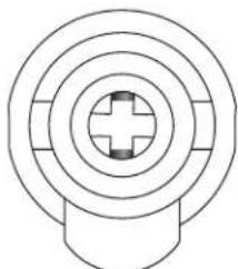
natural_image
Pure concentric circle diagram with a central cross and rounded base (no text or symbols)
natural_image
Pure technical diagram of concentric circles with a central cross symbol, no text or labels present
natural_image
Concentric circles diagram with a central cross and small square at center (no text or symbols)lever catch
3 Preparing the Lever Handle and Cylinder for Installation
3. Insert the cylinder into the lever handle (see Fig.3)
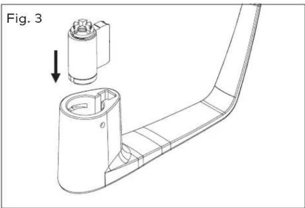
natural_image
Technical line drawing of a mechanical component with an arrow indicating assembly or adjustment (no text or symbols present)- Put the cylinder plug into the lever (see Fig.4)
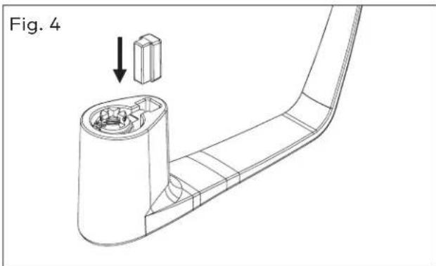
- Making sure that the cylinder plug does not fall out, insert the key into the cylinder. The key will be horizontal. (See Fig. 5).
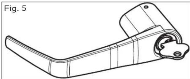
natural_image
Technical line drawing of a mechanical lever component (no text or symbols)CAUTION
If the Lever is Not Assembled with the key in the position shown in Fig. 6 & Fig. 7, the inside mechanism of the lock could be damaged if the lever is rotated and forced.
4 Steps to attach the lever handle to the lock housing
*NOTE: THE POSITION OF THE KEY IS VERY IMPORTANT
- Right-handed Lever handle: Turn the key approximately 90° to 100° clockwise so that it is in the vertical position and the countersink is in the top position. (See Fig. 6)
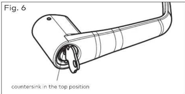
Left-handed lever handle: Turn the key approximately 90^ to 100^ clockwise so that it is in the vertical position and the countersink is in the bottom position. (See Fig. 7)

IMPORTANT
The key and the countersink must be in the positions shown in Figs 6 & 7 before placing the lever handle on the housing or the lever and the override mechanism will not work.
Troubleshooting:
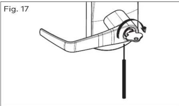
If you have assembled the lever and housing with the key in the wrong position, the key will get stuck. To remove the key, turn it so that it is in the vertical position and insert a small flat screwdriver (see page 15 Fig.17) into the hole under the lever handle to push Lever Catch in (see page11 Fig.2). Remove key. If it is still stuck, turn the key 90° clockwise to the horizontal position and push the Lever Catch in again with the small screwdriver. Remove key.
5 Attaching the Lever Handle to the Lock (with the key as shown in Fig. 6 & Fig. 7)
- Fit the lever handle onto the drive tube. It should rest approximately 1/16" from the body of the housing. (See Fig. 8)
If it can't be pushed that close to the housing, the lever catch is probably not pushed in. Push it in.
If the lever catch is stuck, the override shaft is in the wrong position. The two small indents on the cross of the override shaft must be vertically aligned as in fig. 2
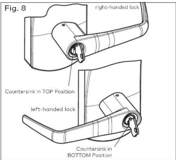
- Press the lever firmly against the housing while turning the key counterclockwise (this applies to both right-handed and left-handed locks) until it is in the horizontal position. (Fig. 9)

CAUTION
If it is not possible to turn the key counterclockwise to complete this step, the spring washer (D, see page 10) may be too tense: (not for lever feel)
Hit the lever carefully with a rubber mallet to loosen the spring washer. (you may want to cover the lever handle with a cloth or other material to protect the finish of the metal)
- Remove the key. The lock will look as shown in Fig.10.
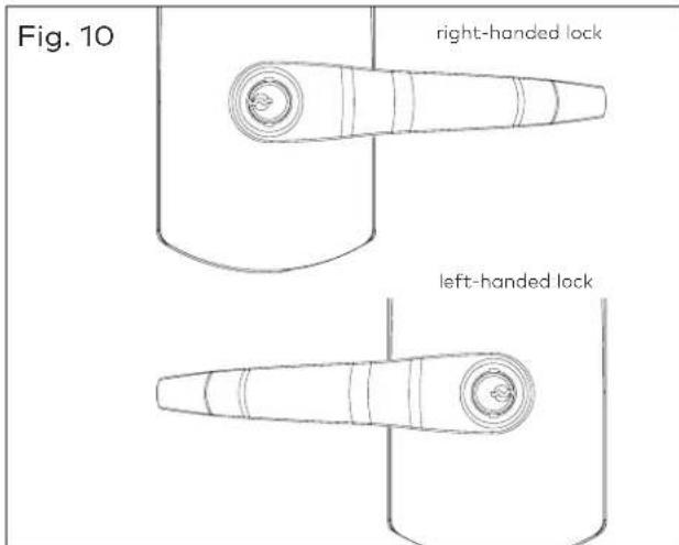
Gently check the rotation of the lever handle. It should easily rotate approximately 45^ .
Troubleshooting:
Right-handed Lock: Turn the lever handle clockwise without forcing it. If it stops at approximately 15°, it was not assembled correctly as shown in step 4 (Fig. 6 & 7). Do not try to force it to turn. Release the lever handle. Insert the small screwdriver (T, page 10) into the small hole on the underside of the lever handle and push in the lever catch. Re-do steps 2, 3, 4 & 5.
Left-handed Lock: Turn the lever handle counter-clockwise without forcing. The drive hub (Fig.14 page14) should not rotate when the lever handle is turned. If it does, it was not assembled correctly as shown in step 4 (Fig. 6 & 7). Release the lever handle. Insert the small screwdriver (T, page 10) into the small hole on the underside of the lever handle and push in the lever catch. Re-do steps 2, 3, 4 & 5.
6 Verify the Attachment of the Lever Handle
IMPORTANT
To verify that the lever handle has been correctly attached to the housing:
- Remove key
- Insert a small flat screwdriver (tool T, page 10) into the hole on the underside of the lever handle and push inthe lever catch.
- Pull on the lever handle.
You should not be able to remove the lever handle. If it comes off of the housing, you did not assemble the lock correctly. Return to steps 2, 3, 4 & 5 and make sure that the lever looks like Fig. 10 and repeat this verification process. (Step 6)
6a Adjust the Lever feel
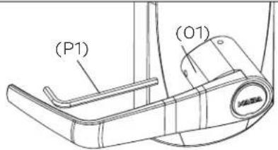
If applicable, to reduce the lever play, using the 5/64 allen key (P1), tighten the set screw (O1) while pushing the lever against the front housing. Make sure the lever rotates properly after tightening the set screw (O1).
Fig. 10A
7 Test the Movement of the Lever Handle (without the key cylinder)
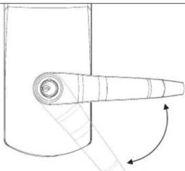
- Turn the handle clockwise (for a right-handed lock) or counter-clockwise (for a left-handed lock)
- Release the handle slowly. It should return freely to its horizontal position. (Fig.11)
Fig. 11
natural_image
Simple line drawing of a mechanical component with a curved arrow indicating rotation (no text or symbols)8 Test the Mechanical Override Function
IMPORTANT
This test can only be performed when the lock is not affixed to the door.
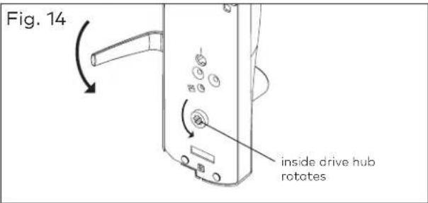
- Without using the key, turn the lever handle clockwise (for Right-handed locks) or counter-clockwise (for Left-handed locks). The inside drive hub should not rotate when the handle turns. (Fig. 12)

- With the lever handle in the horizontal position, insert the key into the cylinder and turn it clockwise until it stops. (This applies to both Right and Left-handed locks, see Fig.13)

natural_image
Technical line drawing of a mechanical lever mechanism with two views (no text or symbols)- Let go of the key, and again turn the lever handle clockwise (for Right-handed locks) or counter-clockwise (for Left-handed locks). Now the inside drive hub should rotate in the same direction as the lever handle when it is turned. (Fig. 14)
8 Test the Mechanical Override Function (Continued)
IMPORTANT
Verify the functionality of the override after the lock is installed on the door:
-
With the door open, insert key in cylinder and turn it clockwise until it stops.
-
Let go of the key and turn the lever handle (clockwise for right-handed and counter-clockwise for left-handed locks). The latch must retract.
-
Extend deadbolt and repeat the above operation (turn key clockwise until it stops), latch and deadbolt must retract completely.
9 Cover the key Hole & Cylinder with the Cap
- The cap has a small groove on one edge (to allow ease of removal) this should be facing down. Insert bottom snap of cap in handle hole below the cylinder. With a small screwdriver, push top snap of cap down while pushing the cap into place to cover the keyhole (Fig. 15)

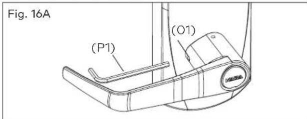
- To remove the cap, insert a small flat screwdriver into this groove and gently pry the cap off, being careful not to damage it. (You may want to cover the bottom of the lever to protect the finish from being scratched through the process of removing the cap). (Fig.16)
Fig. 16

10 How to Change Lock Cylinders
23a. Loosen the set screw (01) to free the lever using Allen Key (P1) (Approx. 1/4 turn).
-
Remove the cap from the lever handle (see step 23, Fig. 16).
-
Insert key.
-
Turn the key clockwise until it stops.
-
Release key.
-
Use a small flat screwdriver to push in the lever catch through the small hole underneath the lever handle (Fig. 17).
natural_image
Technical line drawing of a mechanical lever mechanism with rotation arrow (no text or symbols)-
Pull the lever handle off of the lock housing (be careful not to lose the cylinder plug).
-
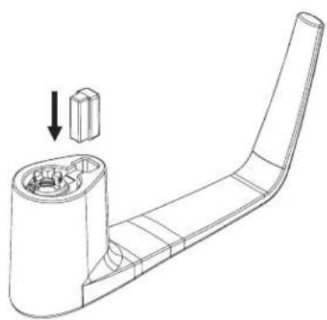
Replace the old cylinder with the new one in the lever handle. Only same kind and same length of cylinder with 2 grooves in cross, in the end of the cylinder plug could be used on the E-730/630 Series locks. (Fig. 18)

10 How to Change Lock Cylinders (continued)
- Re-insert the cylinder plug (Fig. 19)
Fig. 19
natural_image
Technical line drawing of a mechanical component with a cylindrical base and a curved end, showing internal parts and a downward arrow indicating direction (no text or symbols)- While holding the cylinder and plug in place, insert the key
- Turn the key approximately 100° clockwise
- Repeat the steps 1 to 9 to attach the lever handle to the lock housing. (see Fig. 20)
Fig. 20


IMPORTANT
The Key Override itself does not retract the latch or deadbolt. Do not use too much force when turning the key as this may damage the unit. To retract the latch, turn the key clockwise until it stops, release the key and turn the lever handle (H). See page 14
The lever handle must stay in the horizontal position when turning the key (do not try to turn the key while turning the handle) or the override mechanism will not work.
Always keep the door open while installing and verifying the functionality of the E-730/630/750/79E/RT Series lock with the key-card or key override. Do not close the door until you are certain that you have installed the unit correctly.
Preparing the lever handle for Best Removable Core
F-5 Insert 6-pin Best adapter (thicker) into 6-pin interchangeable core or insert 7-pin Best adapter (thinner) into 7-pin interchangeable core. Insert the adapter until it makes contact with the removable core.
F-6 Using the control key, assemble the removable core with its adapter into the lever. Remove control key.
F-7 Insert the change key into the removable core.
Follow the rest of instructions from step 3.5 of page 12

natural_image
Technical line drawing of two mechanical components with no visible text or symbols
natural_image
Technical line drawing of a mechanical lever assembly (no text or symbols)
7 Pins Thinner Adapter

6 Pins
Thicker
Adapter
Note for Contactless 79/RT/E7900 Series customers:
Statement according to FCC part 15.105
This equipment has been tested and found to comply with the limits for a Class B digital device, pursuant to Part 15 of the FCC Rules. These limits are designed to provide reasonable protection against harmful interference in a residential installation. This equipment generates, uses, and can radiate radio frequency energy and, if not installed and used in accordance with the instructions, may cause harmful interference to radio communications. However, there is no guarantee that interference will not occur in a particular installation. If this equipment does cause harmful interference to radio or television reception, which can be determined by turning the equipment off and on, the user is encouraged to try to correct the interference by one or more of the following measures:
- Reorient or relocate the receiving antenna.
- Increase the separation between the equipment and receiver.
- Consult the dealer or an experienced radio/TV technician for help.
Statement according to FCC part 15.21
Modifications not expressly approved by dormakaba could void the user's authority to operate the equipment.
Statement according to FCC part 15.19
This device complies with part 15 of the FCC rules and Industry Canada ICES-003. Operation is subject to the following two conditions: (1) This device may not cause harmful interference, and (2) this device must accept any interference received, including interference that may cause undesired operation.
Lever handle and card reader for fire exit hardware
Classified by Underwriters Laboratories Inc.®
Intended for installation on mortise, rim or vertical rod type devices.
dormakaba
Customer Services & Support
llco: 1.877.468.3555 / + 1.514.340.9025
Saflok: 1.800.999.6213 / + 1.248.837.3700
General Information:
dormakaba.us
Online Consumable Orders:
www.ilcostore.com
www.saflokstore.com
To access all of our easy steps, please
visit our Support Website:
www.kabalodgingsupport.com
- Exit Device Operators 630/750/79E/RT/E7900 Series/ Generation E-730
- Table of contents
- A Checklist
- Each lockset for E-730/630/750/79E/E7900 includes:
- Parts inside hardware bag:
- Messenger / BLE Generation includes:
- Mechanical Override Models ONLY:
- E7900 Messeger/BLE Generation includes:
- Tools Required:
- B Introduction and disclaimers
- IMPORTANT
- WARNING
- CAUTION
- C Prepare the door for the appropriate exit device
- D Install the lock and the exit device
- Install the Mortise (if applicable)
- Install the Outside Lever
- Install the Batteries
- Install Lock & Exit Device on the door
- D Install the lock and the exit device (Continued)
- Install Lock & Exit Device with Messenger/Bluetooth on the door (continued)
- E Test the operation of the E-730/750/79E lock
- (for 630 lock go to Section H) (For RT lock series, please refer to system 6000 manual)
- Panic Bar
- Outside Lever
- Electronics and Card Reader
- A Test the Lock Before Programming
- B Lock Programming
- C Emergency Keycard Access
- F Program the E-730/750/79E/E7900 lock
- FDU
- ATLAS
- Multihousing
- Aurora
- Enterprise
- G Operating the emergency override For RT lock series, please refer to system 6000 manual. For multihousing refer to RezShield manual.
- Electronic override using the FDU:
- There are two possible security levels:
- Hardware Required:
- Minimum Authorization Keycard Required:
- Lteps to activate the E-730/630/750/79E electronic override:
- G Operating the emergency override For RT lock series, please refer to system 6000 manual. For multihousing refer to RezShield manual. (Continued)
- H Test the operation of the 630 lock
- Electronic
- A Programming
- B Code entry and access
- J Installation of the mechanical override
- Parts and Tools List
- Diagram of lock:
- Facing view of drive tube: (E)
- Troubleshooting:
- Attaching the Lever Handle to the Lock (with the key as shown in Fig. 6 & Fig. 7)
- Verify the Attachment of the Lever Handle
- 6a Adjust the Lever feel
- Test the Movement of the Lever Handle (without the key cylinder)
- Test the Mechanical Override Function
- Test the Mechanical Override Function (Continued)
- Cover the key Hole & Cylinder with the Cap
- How to Change Lock Cylinders
- How to Change Lock Cylinders (continued)
- Preparing the lever handle for Best Removable Core
- Note for Contactless 79/RT/E7900 Series customers:
Brand : Dormakaba
Model : Exit Device Operators 630
Category : Emergency Output System