
EcoBreeze ACECFR40200SE6 - Air conditioner SCHNEIDER - Free user manual and instructions
Find the device manual for free EcoBreeze ACECFR40200SE6 SCHNEIDER in PDF.


| Brand | Schneider |
| Model | ACECFR40200SE6 |
| Product Type | Air conditioner (EcoBreeze indirect evaporative cooling system) |
| Frame Size | 40 ft ISO container frame (12.19 m) |
| Frame Dimensions (approx.) | 12.19 m x 2.44 m x 2.59 m (L x W x H) |
| Weight (Frame fully populated, dry) | 14,290 kg (31,440 lb) |
| Weight (Frame fully populated, wet) | 14,630 kg (32,187 lb) |
| Weight per Module | 1,250 kg (2,750 lb) |
| Number of Modules | 8 (for fully populated 40 ft frame) |
| Power Supply | 480 V, 3-phase, 60 Hz |
| Water Supply Pressure | 207-448 kPa (30-65 psig) |
| Water Supply Requirement | Clean potable water |
| Water Connection | 3/4-inch NPT female (2 inlets) |
| Drain Connection | 2-inch NPT female |
| Remote Display | LCD touch screen interface with NEMA case |
| BMS Communication | Modbus via RJ-45 or 3-wire terminal block |
| Operating Temperature (Remote Display) | 0-55°C (32-131°F), humidity 5-95% non-condensing |
| Safety Features | Lockout/tagout, access door locking mechanisms, tension rods for transport |
| Application | Data center cooling |
| Certifications | Complies with national and local electrical codes |
Frequently Asked Questions - EcoBreeze ACECFR40200SE6 SCHNEIDER
User questions about EcoBreeze ACECFR40200SE6 SCHNEIDER
0 question about this device. Answer the ones you know or ask your own.
Ask a new question about this device
Download the instructions for your Air conditioner in PDF format for free! Find your manual EcoBreeze ACECFR40200SE6 - SCHNEIDER and take your electronic device back in hand. On this page are published all the documents necessary for the use of your device. EcoBreeze ACECFR40200SE6 by SCHNEIDER.
USER MANUAL EcoBreeze ACECFR40200SE6 SCHNEIDER
ACECFR20101SE, ACECFR20200SE, ACECFR20201SE, ACECFR40101SE, ACECFR40200SE, ACECFR40201SE
990-3976D-001
Publication Date: June 2014
natural_image
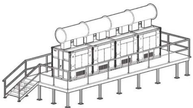
Isometric line drawing of an industrial facility with cylindrical tanks and storage units on a platform (no text or symbols)Schneider Electric IT Corporation Legal Disclaimer
The information presented in this manual is not warranted by the Schneider Electric IT Corporation to be authoritative, error free, or complete. This publication is not meant to be a substitute for a detailed operational and site specific development plan. Therefore, Schneider Electric IT Corporation assumes no liability for damages, violations of codes, improper installation, system failures, or any other problems that could arise based on the use of this Publication.
The information contained in this Publication is provided as is and has been prepared solely for the purpose of evaluating data center design and construction. This Publication has been compiled in good faith by Schneider Electric IT Corporation. However, no representation is made or warranty given, either express or implied, as to the completeness or accuracy of the information this Publication contains.
IN NO EVENT SHALL SCHNEIDER ELECTRIC IT CORPORATION, OR ANY PARENT, AFFILIATE OR SUBSIDIARY COMPANY OF SCHNEIDER ELECTRIC IT CORPORATION OR THEIR RESPECTIVE OFFICERS, DIRECTORS, OR EMPLOYEES BE LIABLE FOR ANY DIRECT, INDIRECT, CONSEQUENTIAL, PUNITIVE, SPECIAL, OR INCIDENTAL DAMAGES (INCLUDING, WITHOUT LIMITATION, DAMAGES FOR LOSS OF BUSINESS, CONTRACT, REVENUE, DATA, INFORMATION, OR BUSINESS INTERRUPTION) RESULTING FROM, ARISING OUT, OR IN CONNECTION WITH THE USE OF, OR INABILITY TO USE THIS PUBLICATION OR THE CONTENT, EVEN IF SCHNEIDER ELECTRIC IT CORPORATION HAS BEEN EXPRESSLY ADVISED OF THE POSSIBILITY OF SUCH DAMAGES. SCHNEIDER ELECTRIC IT CORPORATION RESERVES THE RIGHT TO MAKE CHANGES OR UPDATES WITH RESPECT TO OR IN THE CONTENT OF THE PUBLICATION OR THE FORMAT THEREOF AT ANY TIME WITHOUT NOTICE.
Copyright, intellectual, and all other proprietary rights in the content (including but not limited to software, audio, video, text, and photographs) rests with Schneider Electric It Corporation or its licensors. All rights in the content not expressly granted herein are reserved. No rights of any kind are licensed or assigned or shall otherwise pass to persons accessing this information.
This Publication shall not be for resale in whole or in part.
General Information.... 1
Safety 1
Inspecting the Equipment. 2
Storing the equipment before installation 2
Model Identification .... 3
Model identification label location 3
Frames 3
Modules 3
Other components 3
Access Door and Panel Operation 4
Component Identification.... 5
EcoBreeze Frame and Modules 6
Module — front....7
Remote display interface 7
Site Preparation 8
Incoming power supply requirements 8
Ductwork 8
Water supply 8
Foundation 8
Environment 9
Piping/plumbing diagram 9
10
Refrigeration 10
Service access 11
Weights and Dimensions ....12
Frame 12
Installation 13
Lifting and Rigging.... 13
Mechanical Connections .....14
Position the EcoBreeze 14
Unwrap the equipment 15
Remove the tension rods 16
Lower Module drop-down box 17
Water supply connection 18
Drain 19
Electrical Connections .....21
Power supply to EcoBreeze Frame 22
Remote display interface 23
Building Management System 25
Safety
Read and adhere to the following important safety considerations when working with this cooling unit.
DANGER
HAZARD OF ELECTRIC SHOCK, EXPLOSION, OR ARC FLASH
Turn off all power supplying this equipment before working on the equipment. All electrical work must be performed by licensed electricians. Practice Lockout/Tagout procedures. Do not wear jewelry when working with electrical equipment.
Failure to follow these instructions will result in death or serious injury.
WARNING
HAZARD FROM MOVING PARTS
Keep hands, clothing, and jewelry away from moving parts. Check the equipment for foreign objects before closing the doors and starting the equipment.
Failure to follow these instructions can result in death, serious injury, or equipment damage.
WARNING
DAMAGE TO EQUIPMENT OR PERSONNEL
The equipment is heavy and can easily be tipped. For safety purposes, adequate personnel must be present when moving this equipment.
Failure to follow these instructions can result in death, injury, or equipment damage.
CAUTION
HAZARD TO EQUIPMENT OR PERSONNEL
All work must be performed by Schneider Electric authorized personnel.
Failure to follow these instructions can result in injury or equipment damage.
Inspecting the Equipment
Inspect for missing components. All shipped loose components are identified by part number and description on the bill of lading. Ensure each item is present before accepting delivery of the unit.
Filing a claim. If damage has occurred, or if shipped loose parts are missing, report it immediately to the delivering carrier and note the problem on the receiving copy of the bill of lading. Failure to do so will result in replacement parts and repairs being billed to the customer.
In case of shipping damage, do not operate the equipment. Keep all packaging for inspection by the shipping company and contact Schneider Electric.
Storing the equipment before installation
WARNING
DAMAGE TO EQUIPMENT OR PERSONNEL
- Do not remove tension rods until the EcoBreeze™ Frame is placed and secured on its supports.
- Move the EcoBreeze Frame directly from the truck to its permanent foundation or supports. If it must be stored temporarily, it must be placed on a flat and level surface to avoid damage.
- Leave the protective plastic wrap in place until you are prepared to install the equipment.
Failure to follow these instructions can result in death, serious injury, or equipment damage.

Heavy: Ensure the lifting equipment has sufficient capacity for the load.
The recommended tools for moving the equipment include the following:
Crane
(Frame,
ductwork)

Model Identification
Model identification label location
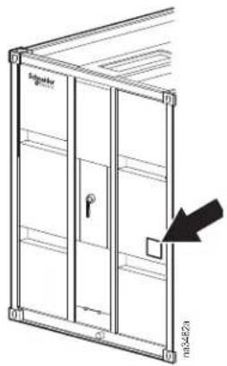
natural_image
Technical line drawing of a door frame with a key inserted, showing internal structure and a black arrow pointing to a component (no text or symbols present)Frames
SKU Description
ACECFR20101SEn* 6 m (20 ft) ISO Frame 400/3/50
ACECFR20200SEn* 6 m (20 ft) ISO Frame 480/3/60
ACECFR20201SEn* 6 m (20 ft) ISO Frame 600/3/60
ACECFR40101SEn* 12 m (40 ft) ISO Frame 400/3/50
ACECFR40200SEn* 12 m (40 ft) ISO Frame 480/3/60
ACECFR40201SEn* 12 m (40 ft) ISO Frame 600/3/60
*Where n is the number of Modules populating the Frame upon order.
Modules
SKU Description
ACEC101SE EcoBreeze Module 400/3/50
ACEC200SE EcoBreeze Module 480/3/60
ACEC201SE EcoBreeze Module 600/3/60
Other components
SKU Description
ACECINS100SE Frame install kit
ACECCP100SE EcoBreeze remote interface panel
ACECSJ100SE EcoBreeze screw-jack assembly
Access Door and Panel Operation
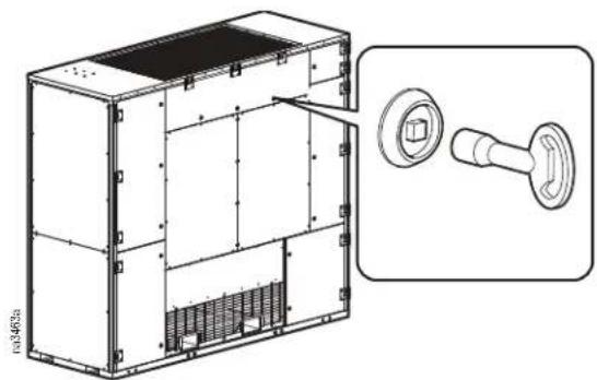
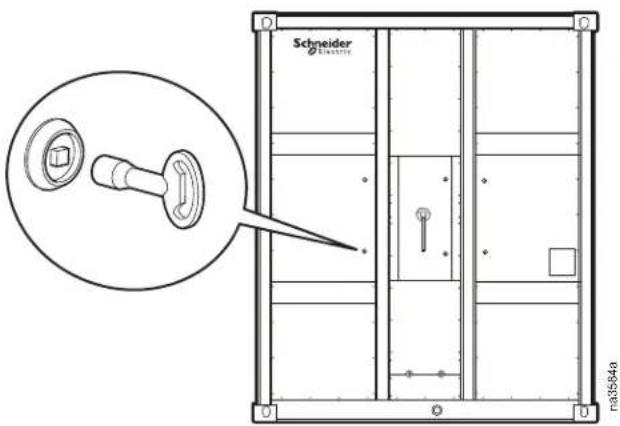
Module access doors and panels have latches with a locking mechanism. Secondary door latches are provided on doors on compartments that have positive air pressure to prevent the doors from opening quickly if a door is opened while the unit is in operation.
| ⚠ WARNING |
| HAZARD OF ELECTRIC SHOCK |
| To avoid possible personal injury or death, re-engage the access door locking mechanism after access to a compartment for inspection or service requirements. |
| Failure to follow these instructions can result in death or serious injury. |
natural_image
Technical line drawing of a modular electronic device with internal components and a close-up inset showing a dial (no text or symbols)Frame access panels and the main power enclosure have locking latches that open with a key.
Component Identification
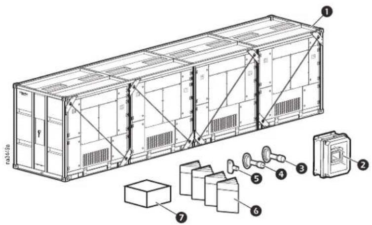
Item Description
Quantity Quantity
20 ft 40 ft
① EcoBreeze Frame and Module assembly* 1 1
2 Remote display interface 1 1
3 Frame electrical panel latch tool 4 4
4 Module access door latch tool 4 8
⑤ Water treatment module signal generator key 1 1
6 Technical manuals 5 5
7 Pipe adapter kit (50 Hz only) 1 1
3/4 NPT x 3/4 - 14 BSPT (4)
2-in. NPT x 2 - 11 BSPT (1)
* Version shown is the 12 m (40 ft) model.
EcoBreeze Frame and Modules
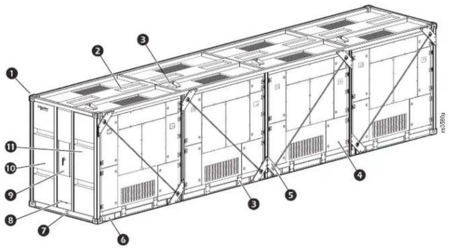
Item Description
1 ISO corner fittings
② Return air inlets
③ Module anchor brackets
4 Module
⑤ Tension rods and mounts
6 Screw-jack mounting points
⑦ Water drain outlet
⑧ Water supply inlets
9 Frame main power enclosure
10 Frame power distribution panel
⑪ Direct digital controller (DDC) panel
Module — front
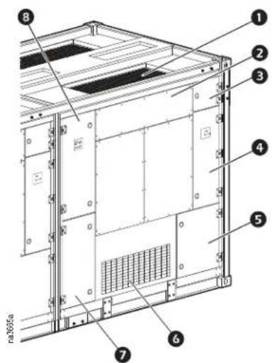
Item Description
1 Condenser coil
② Sprayer head and mist eliminator access door
③ Water coupling and water strainer access door
④ Air filter and DX evaporator coil access door
⑤ Module supply air duct access door
6 Outdoor air intake
⑦ Compressor and wiring connections access door
8 Indoor air fans access door
Remote display interface
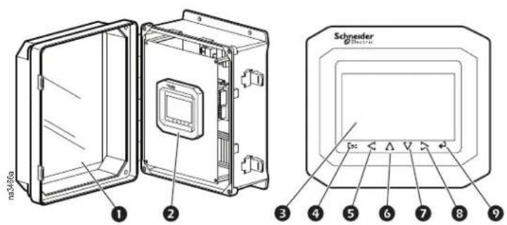
Item Description
① NEMA case
② Display
③ LCD touch screen
④ Escape key
5 Left arrow key
6 Up arrow key
⑦ Down arrow key
8 Right arrow key
9 Enter key
Incoming power supply requirements
NOTE: This equipment requires three-phase electrical service. Electrical service must conform to national and local electrical codes. The equipment must be grounded.
NOTE: To facilitate routing of main power supply wiring, run parallel wires for the main power connections.
Ductwork
Provide supply and return ducting at the site to connect to the supply and return ductwork on the EcoBreeze System.
See the ductwork drawings in submittal package for recommendations for ducting sizes and supply and return duct configurations.
Water supply
Supply water requirements. The water supply must be clean, potable water. The inlet water pressure provided to the unit must be between 207 and 448 kPa (30 and 65 psig). If the water pressure available is less than 207 kPa (30 psig), a booster pump (not supplied) may be needed to operate the equipment properly. If the water pressure available is higher than 448 kPa (65 psig), use an external pressure regulator (not supplied).
NOTE: Installation of back flow prevention and a water hammer arrestor is recommended.
NOTE: For 50 Hz models, use the pipe adapters to make the connections. See “Water supply connection” on page 18.
| NOTICE |
| DAMAGE TO EQUIPMENT |
| External water piping must have adequate freeze protection and must be correctly applied based on local climatic conditions and best practices. Any exposed piping must be electrically heat-traced and insulated (supplied by others). |
| Failure to follow these instructions can result in equipment damage. |
Foundation
Provide a foundation for the EcoBreeze System as recommended in the submittal package. Corner supports must have clamp connectors installed to secure the EcoBreeze Frame. See “Position the EcoBreeze” on page 14. Intermediate supports must have vibration damper pads installed on the top surface before the frame is placed on the permanent supports.
See EcoBreeze Frame Install Kit installation instructions for additional information.
Environment
NOTE: Locating the EcoBreeze system near areas of increased airborne debris may result in more frequent service intervals.
Piping/plumbing diagram
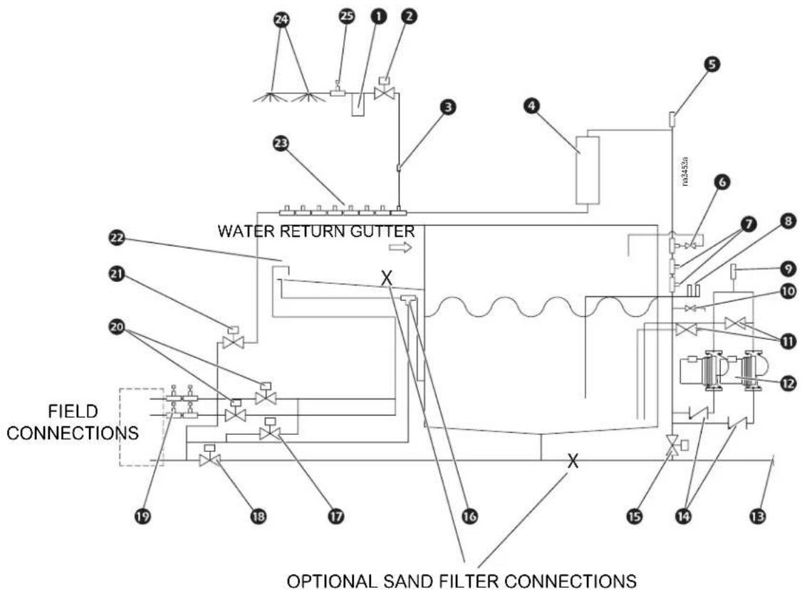
flowchart
graph TD
    A["24"] --> B["25"]
    B --> C["1"]
    C --> D["2"]
    D --> E["3"]
    E --> F["4"]
    F --> G["5"]
    G --> H["6"]
    H --> I["7"]
    I --> J["8"]
    J --> K["9"]
    K --> L["10"]
    L --> M["11"]
    M --> N["12"]
    N --> O["13"]
    O --> P["14"]
    P --> Q["15"]
    Q --> R["16"]
    R --> S["17"]
    S --> T["18"]
    T --> U["19"]
    U --> V["FIELD CONNECTIONS"]
    V --> W["X"]
    W --> X["WATER RETURN GUTTER"]
    X --> Y["X"]
    style A fill:#f9f,stroke:#333
    style B fill:#f9f,stroke:#333
    style C fill:#f9f,stroke:#333
    style D fill:#f9f,stroke:#333
    style E fill:#f9f,stroke:#333
    style F fill:#f9f,stroke:#333
    style G fill:#f9f,stroke:#333
    style H fill:#f9f,stroke:#333
    style I fill:#f9f,stroke:#333
    style J fill:#f9f,stroke:#333
    style K fill:#f9f,stroke:#333
    style L fill:#f9f,stroke:#333
    style M fill:#f9f,stroke:#333
    style N fill:#f9f,stroke:#333
    style O fill:#f9f,stroke:#333
    style P fill:#f9f,stroke:#333
    style Q fill:#f9f,stroke:#333
    style R fill:#f9f,stroke:#333
    style S fill:#f9f,stroke:#333
    style T fill:#f9f,stroke:#333
    style U fill:#f9f,stroke:#333
    style V fill:#f9f,stroke:#333
    style W fill:#f9f,stroke:#333
    style X fill:#f9f,stroke:#333
    style Y fill:#f9f,stroke:#333
    style Z fill:#f9f,stroke:#333
Item Description Item Description
① Clear T-strainer
② Two-way motorized valve*
3 Quick connect coupling
4 Water treatment module
5 Automatic vent
6 Pressure relief valve
⑦ Conductivity sensors
8 Water level sensors
9 Pump suction vent valve
10 Water sample service valve
⑪ Pump suction isolation valve
12 Redundant water pumps
13 Drain line cap
14 Check valves
15 Pump line drain solenoid valve
16 Basin overflow
⑰ Supply water piping drain solenoid valve**
18 Basin drain valve
19 Water supply A & B pressure switches***
20 Supply water A & B solenoid valves**
21 Blow down valve
22 Basin water supply pipe
23 Piping to other modules
24 Spray nozzles
25 Module water pressure switch
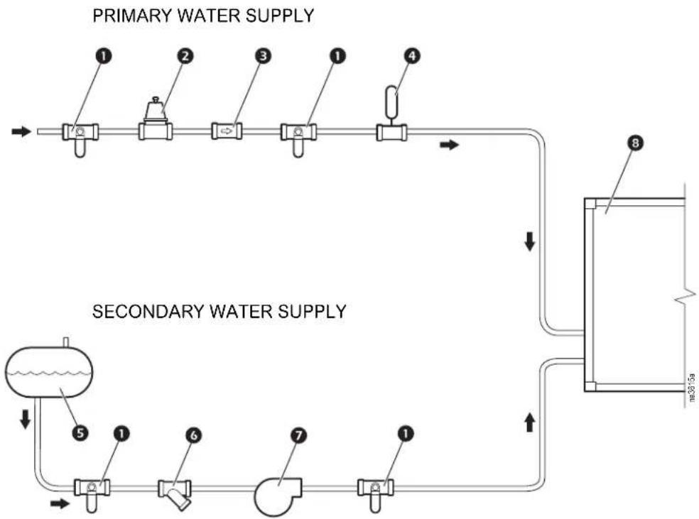
flowchart
graph TD
    A["Primary Water Supply"] --> B["1"]
    B --> C["2"]
    C --> D["3"]
    D --> E["4"]
    E --> F["5"]
    F --> G["6"]
    G --> H["7"]
    H --> I["8"]
    I --> J["Secondary Water Supply"]
    style A fill:#f9f,stroke:#333
    style J fill:#bbf,stroke:#333
Item Description
① Shut-off
② Water pressure reducing valve (if necessary)
3 Backflow preventer
4 Water hammer arrestor
5 Alternate water supply (if available)
6 Inline strainer
⑦ Water pressure booster pump (if necessary)
8 EcoBreeze Frame
Note: All plumbing components shown are field installed.
Refrigeration
Each EcoBreeze Module contains its own closed refrigeration circuit. No field connections are required.
Service access
Install a service platform (not supplied) to facilitate maintenance activities. Regular maintenance activities require a of minimum 1219 mm (48 in.) clearance on all sides to remove, maneuver, and install Modules and components.
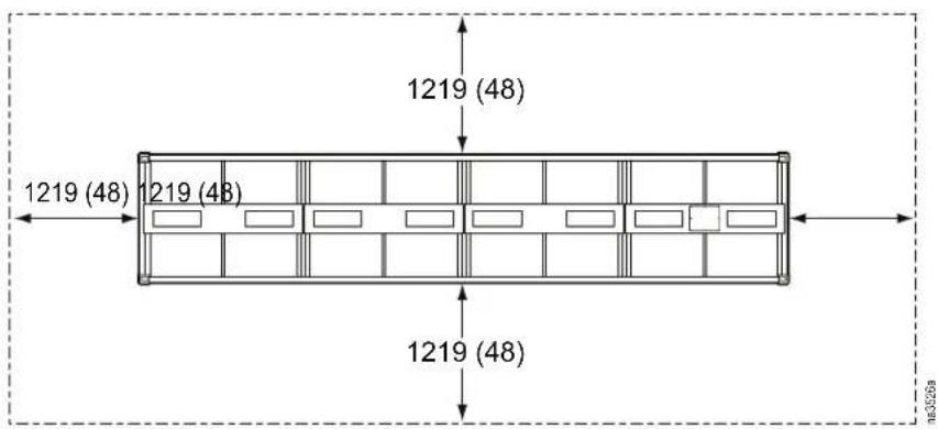
NOTE: Consider local soil conditions, codes, and loading when determining appropriate support footings.
To prevent short cycling of outdoor air, each EcoBreeze Frame must have a minimum of 1219 mm (48 in.) clearance on each side, totaling 2438 mm (96 in.) between Frames, and 1219 mm (48 in.) at the end of the Frame.
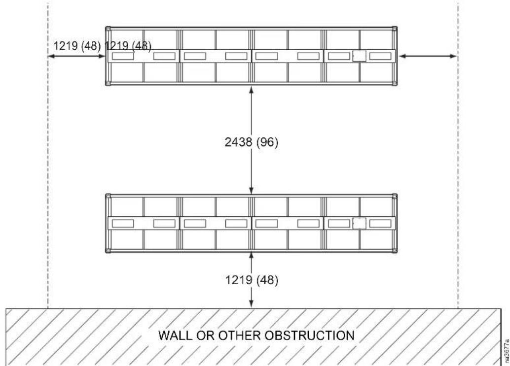
* Dimensions are shown in millimeters with inches in parentheses.
Frame
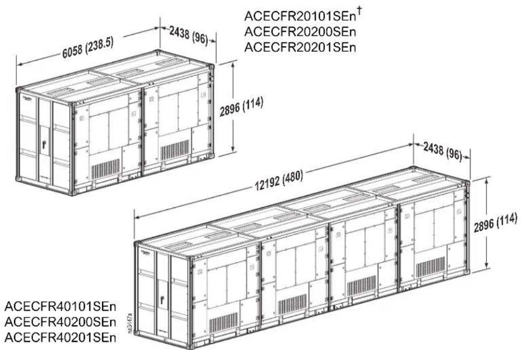
* Dimensions are shown in millimeters, with inches in parentheses.
Where n is the number of Modules populating the Frame upon order.
Frame (fully populated with Modules) Weight (dry)
ACECFR20101SE4, ACECFR20200SE4, ACECFR20201SE4 7 863 kg (17,300 lb) ACECFR40101SE8, ACECFR40200SE8, ACECFR40201SE8 14 290 kg (31,440 lb)
Frame (with Modules and water) Weight (wet)
ACECFR20101SE4, ACECFR20200SE4, ACECFR20201SE4 8 203 kg (18,047 lb) ACECFR40101SE8, ACECFR40200SE8, ACECFR40201SE8 14 630 kg (32,187 lb)
Frame (no Modules) Weight
ACECFR20101SE0, ACECFR20200SE0, ACECFR20201SE0 2 863 kg (6,300 lb) ACECFR40101SE0, ACECFR40200SE0, ACECFR40201SE0 4 290 kg (9,440 lb)
Module
Weight
ACEC101SE, ACEC200SE, ACEC201SE 1 250 kg (2,750 lb)
Lifting and Rigging
WARNING
DAMAGE TO EQUIPMENT OR PERSONNEL
- Do not remove tension rods until the EcoBreeze Frame is placed and secured on its supports.
- Before lifting the EcoBreeze Frame, ensure the lifting equipment is adequately sized for the load.
- Lift and rig the EcoBreeze Frame from the top four ISO corners only.
- Move the EcoBreeze Frame directly from the truck to its permanent foundation. If the Frame must be placed elsewhere temporarily, it must be placed on a flat and level surface in order to avoid damage.
- Check for overhead obstructions such as power cables.
- Maintain a minimum safe distance while equipment is hoisted.
• Control access of personnel at lift site.
Failure to follow these instructions can result in death, serious injury, or equipment damage.
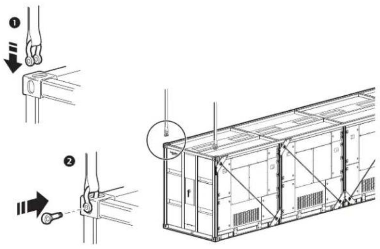
EcoBreeze Frame. The EcoBreeze Frame is not equipped with forklift pockets. Lift and rig only from the four upper ISO corner blocks on each EcoBreeze Frame using a crane.
Recommended horizontal sling angles are greater than 45 degrees. Lifting equipment must be rated for at least 18 144 kg (40,000 lb) for lifting a 12.2 m (40 ft) Frame, and at least 12 247 kg (27,000 lb) for a 6 m (20 ft) Frame.
Mechanical Connections
Install the EcoBreeze Frame per the EcoBreeze Frame Install Kit instructions.
Position the EcoBreeze
NOTE: The power and plumbing connections for the EcoBreeze Frame are located on the end where the unpacking sheet is placed on the protective wrap. Typically this is the end that will face the building.
- Ensure that clamp connectors and vibration damper pads are installed per the EcoBreeze Frame Install Kit instructions.
- Use a crane with sufficient lifting capacity to place the EcoBreeze onto the permanent supports. Typically the end of the frame with plumbing and power connections is placed nearest to the building.
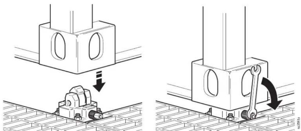
- Using a 15/16-in. open-end wrench to turn the drive stud, lock down the clamp connectors located at each of the four corners. Maximum torque on the drive stud is 68 N-m (50 ft/lb).
Unwrap the equipment
NOTICE
DAMAGE TO EQUIPMENT
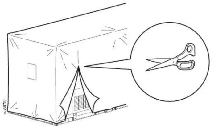
- Do not remove the plastic wrap until the EcoBreeze Frame is placed on its permanent supports and you are prepared to install the return air ductwork. If the plastic is removed, ensure that the return air plenums on top of the Frame are protected.
- When removing protective plastic wrap, be careful to cut only the plastic and not damage the exterior of the equipment.
- The plastic wrap protects the return air plenum openings on top of the Frame until the return air ductwork is installed.
Failure to follow these instructions can result in equipment damage.
Remove the tension rods
natural_image
Technical line drawing of a multi-story container with structural supports and mounting brackets, showing internal compartments and mounting details (no text or symbols)WARNING
DAMAGE TO EQUIPMENT OR PERSONNEL
- Loosen the nuts on the ends of the tension rods to relieve tension before removing tension rod brackets.
- Do not remove the tension rods until EcoBreeze Frame is placed and secured on its supports.
- Move the EcoBreeze Frame directly from the truck to its permanent foundation or supports. If it must be stored temporarily, it must be placed on a flat and level surface to avoid damage.
Failure to follow these instructions can result in death, serious injury, or equipment damage.
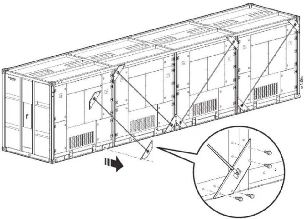
Tension rods are installed diagonally across each Module bay to provide support during shipping.
- Release tension on the rods by loosening the nuts on the ends of the tension rods.
- Using an M12 wrench, remove the eight bolts securing the tension rod brackets.
- Remove the tension rods and brackets.
Lower Module drop-down box
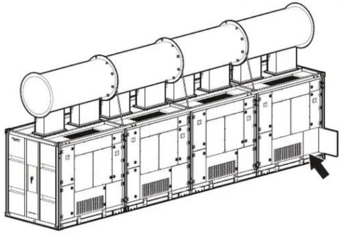
- Open the lower-right door on each Module.
-
For shipping, the drop-down box is secured upside down inside the Module. Remove the screws securing the drop-down box (a).
NOTE: The screws will be re-used to install the drop-down box. -
Turn the drop-down box over (b) so it faces right-side up (c).
natural_image
Technical line drawing of a multi-tiered industrial equipment unit with cylindrical tanks and internal compartments (no text or symbols)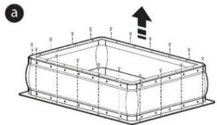
natural_image
Technical line drawing of a rectangular container with internal structure and upward arrow indicator (no text or symbols)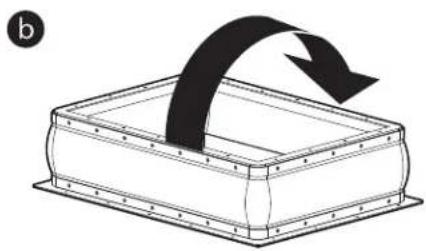
natural_image
Diagram of a rectangular container with a curved arrow indicating rotation or movement (no text or symbols)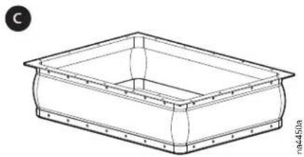
natural_image
Line drawing of a rectangular basin or container with flanged ends and a central opening (no text or symbols)-
Drop the drop-down box through the opening in the bottom of the Module and attach it to the Module with the supplied screws (a).
-
Line up the drop-down box with the supply air transition and attach it to the supply air transition (b).
NOTE: The drop-down box is flexible enough to adjust for slight misalignments.
NOTE: Hardware to attach the drop-down box to the supply air transition is field supplied.
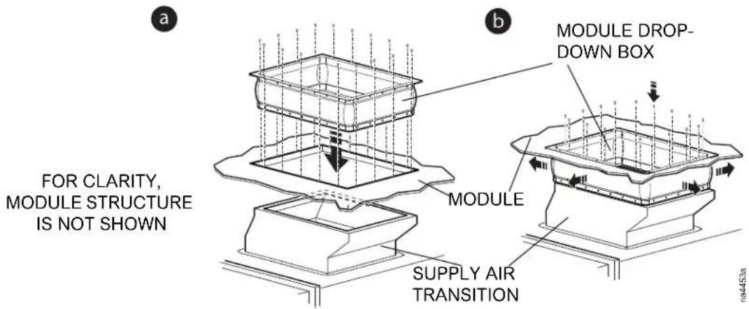
- Locate the insulation strips packed in the ship-loose kit.
- Remove the backing from the insulation and apply the insulation around the air transition ducts.
- Open the damper on the supply air transition.
Water supply connection
NOTE: There are two water supply inlets on the EcoBreeze Frame. Use separate sources if possible to provide a redundant water supply.
NOTICE
DAMAGE TO EQUIPMENT
Install adequate freeze protection (not supplied) on all external water piping.
Freeze protection (which may consist of any combination of insulation and electric heat-tracing) must be correctly applied based on local climatic conditions and best practices.
Failure to follow these instructions can result in equipment damage.
Sand filtration connections are provided if further filtration of the water supply is required. Sand filtration systems can be acquired from a third-party vendor.
Connect the water supply to the two 3/4-inch water supply fittings on the EcoBreeze Frame. If necessary, make the connections using the appropriate fittings from the pipe adapter kit. See "Component Identification" on page 5.
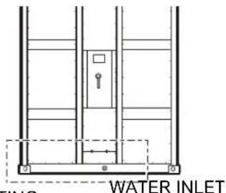
WATER DRAIN
(60 Hz) 2-in. NPT FEMALE FITTING
(50 Hz) 2 - 11 BPST PIPE ADAPTER
(60 HZ) 3/4-in. NPT FEMALE FITTING
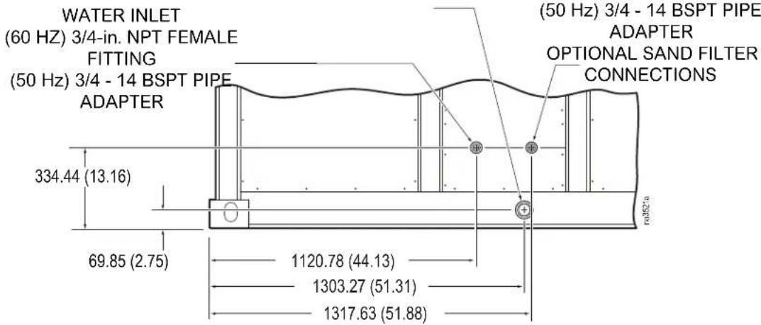
* Dimensions are shown in millimeters with inches in parentheses.
Drain
Connect the external 2-in. drain line on the EcoBreeze Frame to an open drain used for collection of wastewater. If necessary, make the connection using the appropriate fitting from the pipe adapter kit. See "Component Identification" on page 5.
NOTE: Separate the drain line from the EcoBreeze Frame and the external drain line by a 50 mm (2 in.) air gap in order to prevent back up of contaminated water into the cooling system.
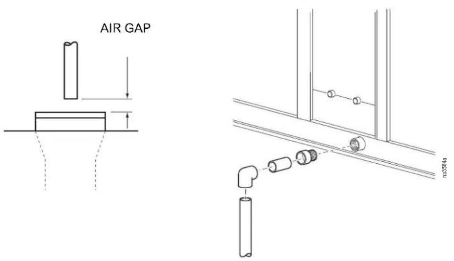
NOTE: Pitch the external drain piping at a minimum of 25 mm (1 in.) per 3048 mm (10 ft) towards the wastewater drain.
Electrical Connections
The electrical connections required are the following:
- Power to Frame
• Control (remote display interface) - Communication - Building Management System (BMS) - optional
Make all electrical connections in accordance with applicable industry guidelines as well as national and local codes.
Make all low-voltage connections, including data and control connections, with properly insulated wires. The low-voltage wires and connections must have at least 300V insulation.
⚠️ ⚠️ DANGER
HAZARD OF ELECTRIC SHOCK
Use a voltmeter to ensure that power is turned off before making any electrical connections.
Failure to follow these instructions will result in death or serious injury.
NOTE: Three-phase electrical service is required. Electrical service must conform to national and local electrical codes.
DANGER
HAZARD OF ELECTRIC SHOCK, EXPLOSION, OR ARC FLASH
Turn off all power supplying this equipment before working on the equipment. All electrical work must be performed by licensed electricians. Practice Lockout/Tagout procedures. Do not wear jewelry when working with electrical equipment.
Failure to follow these instructions will result in death or serious injury.
WARNING
HAZARD TO EQUIPMENT AND PERSONNEL
Only Schneider Electric authorized personnel may energize the equipment.
Failure to follow these instructions can result in death, serious injury, or equipment damage.
- Use a punch tool to create an access hole as needed for power supply wires entering the main power enclosure.
- Attach the conduit connector to the access hole on the main power enclosure.
NOTE: A service loop is factory-installed in the main power enclosure.
- If permitted by local and national codes, route the cable to the disconnect switch as shown. If local and national codes do not permit service loops, make all connections per code.
- Connect the power wiring to the disconnect switch. Connect the phases as marked next to the disconnect switch.
- Connect the ground wire to the grounding lug beside the disconnect switch.
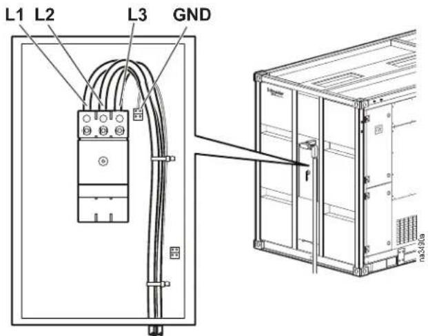
Remote display interface
NOTICE
DAMAGE TO EQUIPMENT
Damage to LCD display will result from exposure to temperatures below 0^ C ( 32^ F). Outdoor installations will require a third-party heat source as needed to ensure the LCD display is not subjected to temperatures below 0^ C ( 32^ F).
Failure to follow these instructions can result in equipment damage.
See EcoBreeze remote display installation instructions for additional information.
The remote display interface enclosure contains the LCD display that is used to control the EcoBreeze from a remote location. The EcoBreeze connects to the remote display interface over an expansion bus.
NOTE: Separate incoming power cables from low voltage wiring by 150 mm (6 in.).
NOTE: Communication wiring from the EcoBreeze to the remote display interface enclosure must be a minimum of 24-gauge, 3-core wire with shield with a maximum length of 300 m (984 ft).
- Install the remote display interface enclosure in the desired location.
IMPORTANT: For outdoor applications, use weather-proof conduit connectors.
OPERATING CONDITIONS: Ambient temperature 0 - 55°C (32 - 131°F). Relative humidity 5% - 95% non-condensing.
NOTE: Connect shield wire to GND.
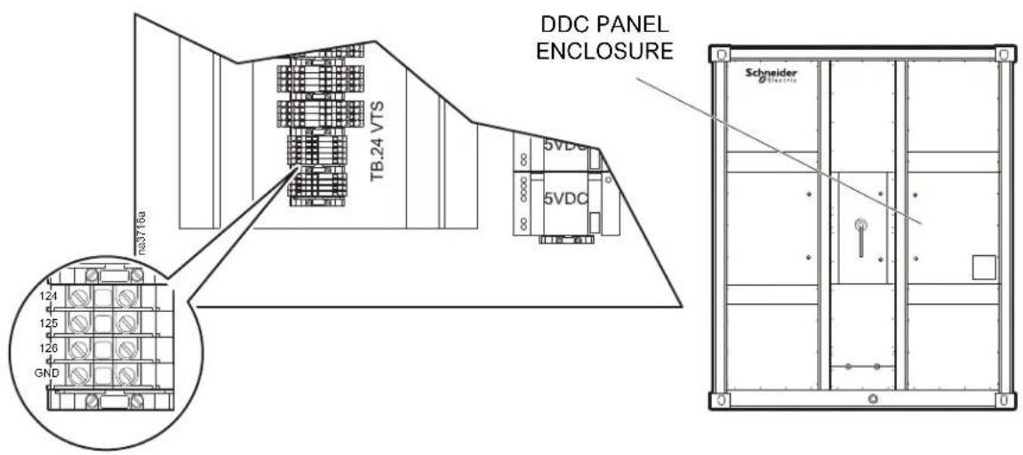
- Connect the bus wiring to the contacts labeled 124, 125, and 126 on the expansion bus terminal block, located behind the direct digital controller (DDC) access door on the Frame.
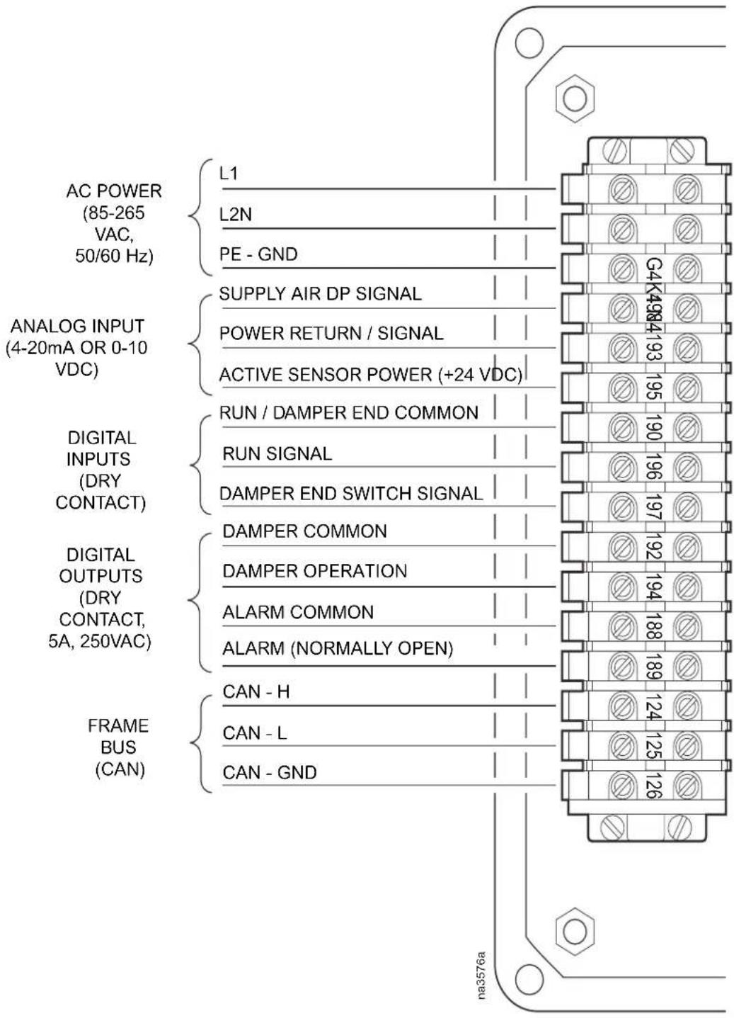
- Wire the expansion bus to the 124, 125, and 126 contacts on the terminal block in the remote display interface enclosure.
Building Management System
The Modbus interface allows the EcoBreeze System to communicate with a building management system (BMS).
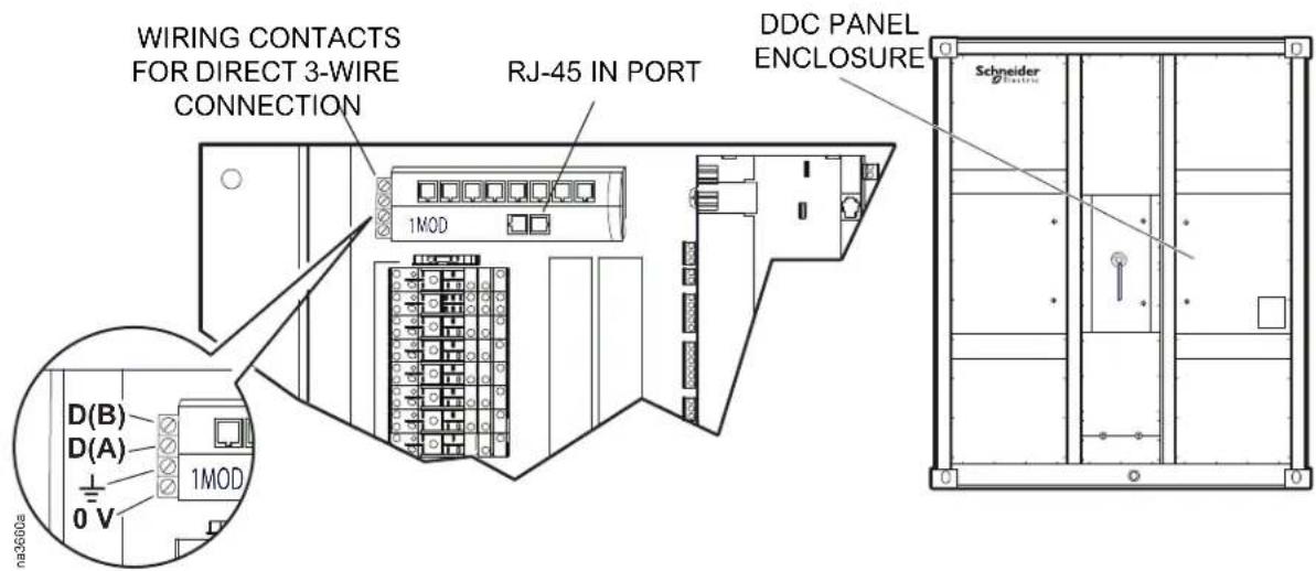
The Modbus connection is available in two locations on the Modbus hub:
- RJ-45 In port
• 3-wire on terminal block
For an RJ-45 connection, wire as follows:
Pin 4 D(A) Pin 5 D(B) Pin 8 Ground
For a direct 3-wire connection, connect to the corresponding contacts on the green terminal block on the side of the Modbus hub. No connection is necessary to the 0V contact.
Worldwide Customer Support
Customer support is available at no charge via e-mail or telephone. Contact information is available at www.apc.com/support/contact.
© Schneider Electric is owned by Schneider Electric Industries S.A.S., or its affiliated companies. All other trademarks are property of their respective owners.
- Schneider Electric IT Corporation Legal Disclaimer
- General Information.... 1
- Component Identification.... 5
- Site Preparation 8
- Weights and Dimensions ....12
- Installation 13
- Mechanical Connections .....14
- Electrical Connections .....21
- Safety
- DANGER
- WARNING
- CAUTION
- Inspecting the Equipment
- DAMAGE TO EQUIPMENT OR PERSONNEL
- Model Identification
- Frames
- Modules
- Other components
- Access Door and Panel Operation
- Component Identification
- EcoBreeze Frame and Modules
- Item Description
- Module — front
- Remote display interface
- Ductwork
- Water supply
- Foundation
- Environment
- Piping/plumbing diagram
- Item Description Item Description
- Refrigeration
- Service access
- Lifting and Rigging
- Mechanical Connections
- Position the EcoBreeze
- NOTICE
- DAMAGE TO EQUIPMENT
- Lower Module drop-down box
- Water supply connection
- Drain
- Electrical Connections
- ⚠️ ⚠️ DANGER
- HAZARD OF ELECTRIC SHOCK
- HAZARD OF ELECTRIC SHOCK, EXPLOSION, OR ARC FLASH
- HAZARD TO EQUIPMENT AND PERSONNEL
- Building Management System
- Worldwide Customer Support
Brand : SCHNEIDER
Model : EcoBreeze ACECFR40200SE6
Category : Air conditioner