MSS-003 - Saw Ozito - Free user manual and instructions
Find the device manual for free MSS-003 Ozito in PDF.


| Brand | Ozito |
| Model | MSS-003 |
| Product Type | Circular Saw |
| Power Source | Corded Electric |
| Voltage | 230V |
| Power Input | 1200 W |
| No-Load Speed | 5000 rpm |
| Blade Diameter | 185 mm |
| Cutting Depth at 90° | 65 mm |
| Cutting Depth at 45° | 48 mm |
| Weight | 4.5 kg |
| Dimensions (L x W x H) | 320 x 250 x 280 mm |
| Laser Guide | Yes |
| Dust Extraction Port | Yes, 35 mm |
| Spindle Lock | Yes |
| Blade Guard | Retractable |
| Safety Switch | Lock-off button |
| Included Accessories | 24-tooth TCT blade, rip fence, hex key |
| Maintenance | Clean air vents regularly; lubricate bearings annually |
| Reparability | Spare parts available: blades, carbon brushes, switch |
Frequently Asked Questions - MSS-003 Ozito
User questions about MSS-003 Ozito
0 question about this device. Answer the ones you know or ask your own.
Ask a new question about this device
Download the instructions for your Saw in PDF format for free! Find your manual MSS-003 - Ozito and take your electronic device back in hand. On this page are published all the documents necessary for the use of your device. MSS-003 by Ozito.
USER MANUAL MSS-003 Ozito
2 Year Replacement Warranty
MSS-003
CAUTION: Read this instruction manual before using this tool.
natural_image
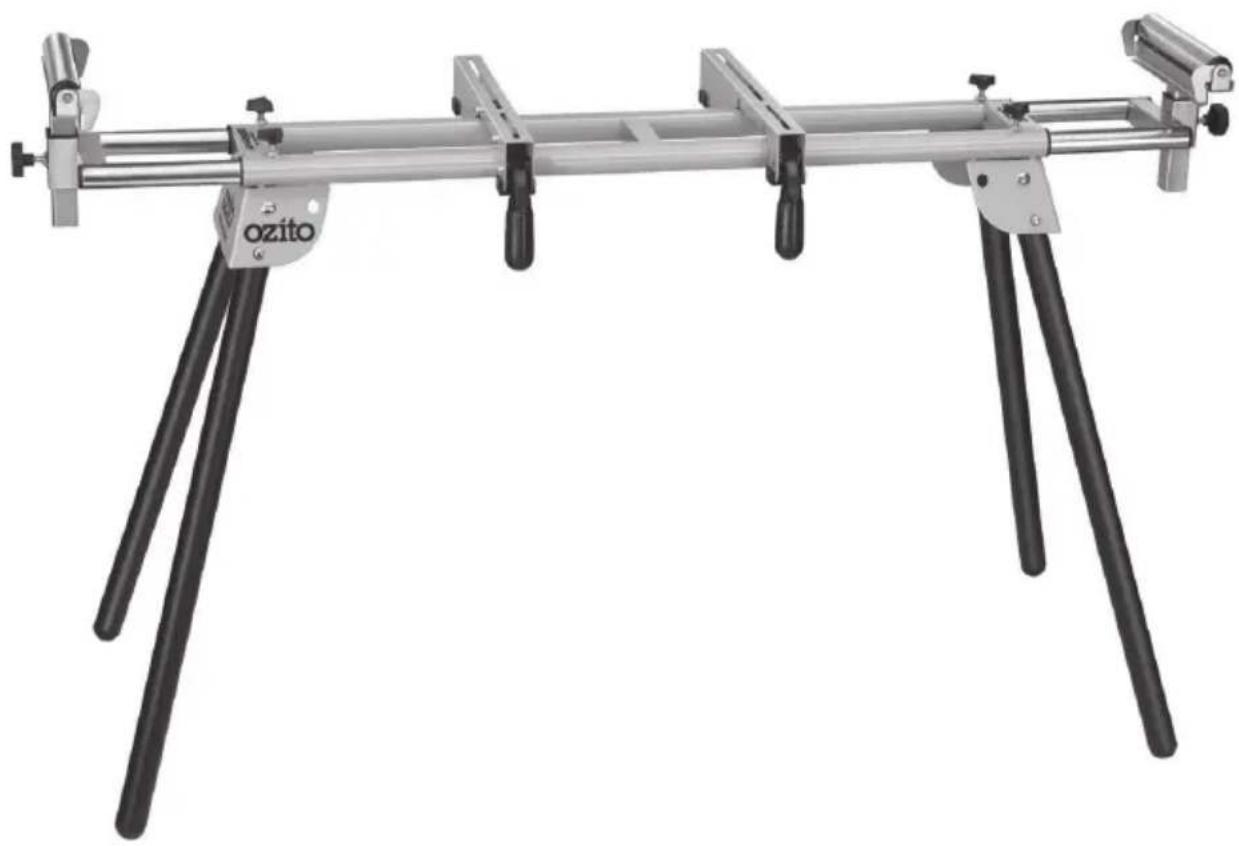
Mechanical support device with black and silver legs, labeled 'ozito' on the base (no additional text or symbols visible)SPECIFICATIONS - MODEL NO. MSS-003
Width (extended): 2050mm
Width (not extended): 1055mm
Height: 820mm
Roller size: 230mm
Weight capacity: 150kg
Weight (tool only): 13.4kgs
KNOW YOUR PRODUCT
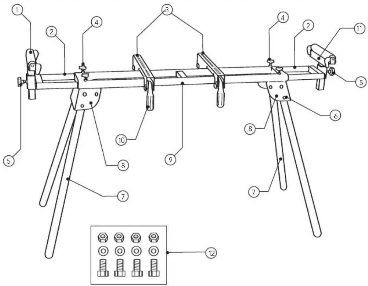
- Work support roller
- Extension bars
- Mitre saw mounts
- Extension bar locking knobs
- Support roller locking knobs
-
Leg release buttons
-
Foldable leg
- Leg support
- Mitre saw rail tubes
- Mitre saw mount handle
- Material stop
- Mitre saw fixing bolts, nuts and washers
TABLE OF CONTENTS
SPECIFICATIONS...... Page 1
KNOW YOUR PRODUCT......Page 1
INTRODUCTION...... Page 3
GENERAL SAFETY INSTRUCTIONS......Page 3
ADDITIONAL SAFETY INSTRUCTIONS
FOR MITRE SAW STANDS......Page 4
ASSEMBLY.... Page 5
OPERATION......Page 7
MAINTENANCE...... Page 9
SPARE PARTS......Page 9
CONTENTS......Page 10
WARRANTY......Page 11
INTRODUCTION
Congratulations on purchasing an Ozito Mitre Saw Stand (MSS-003). We aim to provide quality tools at an affordable price.
We hope you will enjoy using this tool for many years. Your Mitre Saw Stand has been designed for the mounting of mitre saws. It is intended for DIY use only.
GENERAL SAFETY INSTRUCTIONS
- Keep work areas clean. Cluttered work areas can cause accidents.
- Consider work area environment. Keep the work area well lit.
- Keep children away. Do not allow children, visitors or animals to come near the work area.
- Do not overreach. Keep proper footing and balance at all times.
- Stay alert. Watch what you are doing. Use common sense. Do not operate a saw mounted to the stand when you are tired.
- Users. This appliance is not intended for use by young children or infirmed persons without supervision. Young children should be supervised to ensure that they do not play with this appliance.
ADDITIONAL SAFETY INSTRUCTIONS FOR MITRE SAW STANDS
- Always ensure the mitre saw base is properly secured to the stand prior to operation.
• Always ensure the stand legs have been locked into place prior to operation.
• Take care when moving the stand especially when a mitre saw is mounted. - Do not use the stand for any other purpose than what it is intended for.
- Do not use the stand as a stepping stool or ladder.
- Make sure all moving parts are free from interference.
- Keep hands clear of all moving parts.
- Ensure the Mitre Saw Stand is set up on firm ground in a stable manner.
- Use the Mitre Saw Stand in a dry place protected from the rain.
- Be aware of overbalancing. When a large piece is cut from one end of a job, the remaining piece may be heavy enough to over-balance the Mitre Saw Stand. Always ensure the workpiece is well supported.
- When transporting the Mitre Saw Stand in a vehicle, always tie it down to prevent movement and possible damage.
- Check to make sure that all fixing screws and knobs are tight and all legs are locked into position before operation.
- The Mitre Saw Stand must be used only for its prescribed purpose. Any use other than those mentioned in these instructions will be considered a case of misuse. Ozito Industries shall not be liable for any damage or injury resulting from such cases of misuse.
- Ozito Industries shall not be liable for any changes made to the Mitre Saw Stand nor for any damage resulting from such changes.
ASSEMBLY
Leg Assembly
Note: This process may be easier with the assistance of another person.
- Remove the Mitre Saw Stand from the packaging.
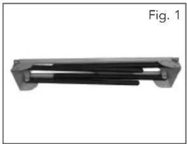
- Carefully tilt the mitre saw rail tubes (9) to one side so you can see the foldable legs (7) underneath (Fig. 1).
- Whilst holding the mitre saw rail tubes (9), push in the leg release button (6) and extend a foldable leg (7) all the way out so that the leg release button (6) locks into the outside holes of the leg support (8) (Fig. 2).
- Repeat for all four foldable legs (7).
- When all four foldable legs (7) have been secured in position, turn the Mitre Saw Stand the correct way up and ensure all the foldable legs (7) are properly secured.
natural_image
Mechanical component labeled Fig. 1, showing a cylindrical rod or bracket with flanged ends (no text or symbols on the object itself)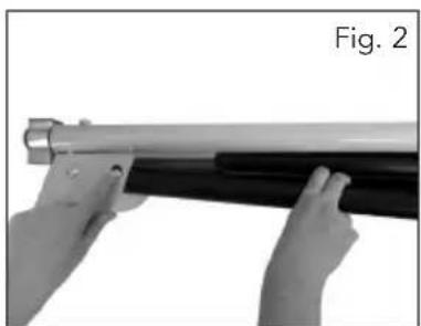
natural_image
Close-up of hands holding a metal rod with a black handle, labeled 'Fig. 2' (no other text or symbols)Fitting the Extension Bar Locking Knobs
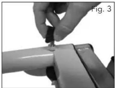
- Fit two extension bar locking knobs (4) to each end of the Mitre Saw Stand and secure to lock the extension bar (2) into position (Fig. 3).
natural_image
Close-up of a hand adjusting a small metallic component on a cylindrical object (no text or symbols visible)Fitting the Work Support Rollers
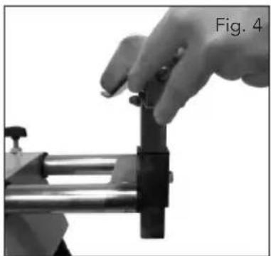
- Fit a work support roller (1) into the fixing hole at one end of the Mitre Saw Stand (ensure that the material stops are facing inwards) (Fig. 4).
natural_image
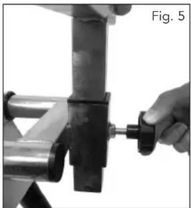
Close-up of a hand operating a mechanical clamp or fixture, labeled 'Fig. 4' (no other text or symbols visible)- Secure the work support roller (1) by inserting and tightening the support roller locking knob (5) (Fig. 5) by turning clockwise.
natural_image
Close-up of a hand adjusting a mechanical component with a black clip (no visible text or symbols)- Repeat for the opposite side.
ASSEMBLY (cont.)
Fixing the Mitre Saw Mounts
-
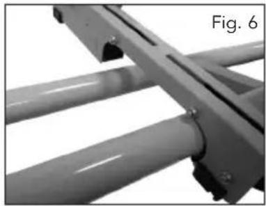
Place the mitre saw mounts (3) on top of the mitre saw rail tubes (9), ensure that the mitre saw mount handles (10) are positioned at the front of the mitre saw rail tubes (9) (Fig. 6).
-
Secure the mitre saw mounts (3) by pushing down the mitre saw mount handle (10) to lock them in position (Fig. 7).
natural_image
Close-up of metallic structural beams with mounting holes, labeled Fig. 6 (no text or symbols on the beams themselves)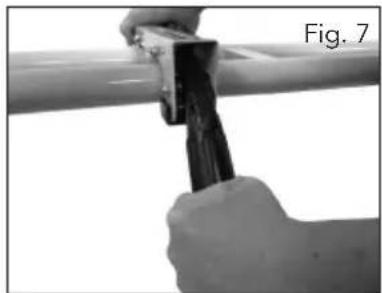
natural_image
Close-up of hands using a tool to handle a pipe (no text or symbols visible)OPERATION
Adjusting the Extension Bars
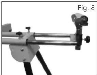
- Loosen the two extension bar lock knobs (4).
- Extend the extension bar (2) to the required distance in order to properly support the workpiece (Fig. 8).
- Tighten the two extension bar locking knobs (4).
- Repeat for the opposite side as required.
natural_image
Mechanical device with articulated arms and mounting bracket, labeled Fig. 8 (no text or symbols on the device itself)Adjusting the Work Support Rollers
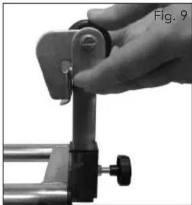
- Loosen the support roller locking knob (5).
- Adjust the height of the work support roller (1) as required to support the workpiece (Fig. 9).
- Tighten the support roller locking knob (5) to secure the work support roller (1) in position.
natural_image
Close-up of a hand adjusting a mechanical clamp or bracket component (no visible text or symbols)Material Stops
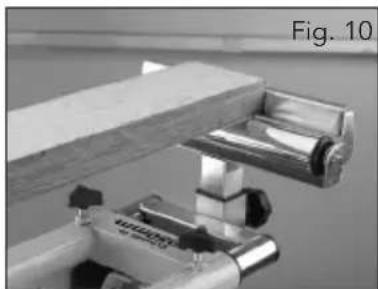
- The Mitre Saw Stand features material stops (11) which allow repetitive cuts to be made quickly and accurately.
- Lift the material stop (11) so it is in the raised position.
-
Adjust the extension bars until they correspond to the desired cutting length.
-
Place the end of the workpiece against the material stop and commence the cut (Fig. 10).
natural_image
Close-up of a mechanical clamp or bracket assembly with metal parts, labeled Fig. 10 (no readable text or symbols)OPERATION (cont.)
Attaching a Mitre Saw
Your mitre saw should have four fixing holes, one hole in each corner of the base. If the mitre saw does not have four holes, do not place it on this Mitre Saw Stand as it cannot be properly secured.
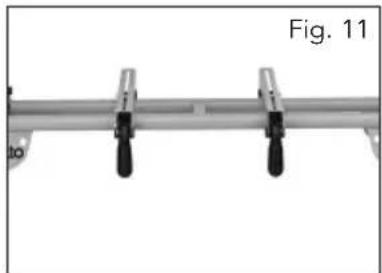
- Adjust the mitre saw mounts (3) roughly to the width of the mitre saw base (Fig. 11).
- Place the mitre saw on the mitre saw mounts (3) and line up the holes in the mitre saw base with the grooves in the mitre saw mounts (3).
- Feed a bolt (12) through the bottom of the mitre saw mount (3) followed by the base of your mitre saw.
- Fit a flat washer (12) over the bolt and secure using a nut (12) (Fig. 12).
- Repeat steps 1-3 for the remaining three holes in the mitre saw using the remaining bolts, nuts and washers (12).
natural_image
Mechanical clamp or bracket with two black clamps, labeled Fig. 11 (no text or symbols on the clamp itself)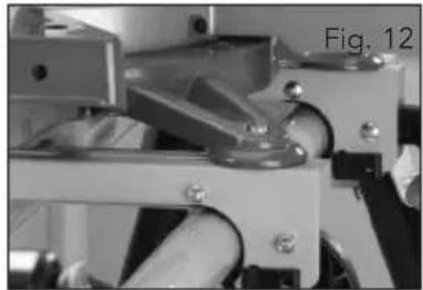
natural_image
Mechanical assembly with metallic components and a cylindrical shaft (no visible text or symbols)Note: During operation and before starting a new job, ensure that all screws and nuts are tightened correctly and securely.
Storage and Transport
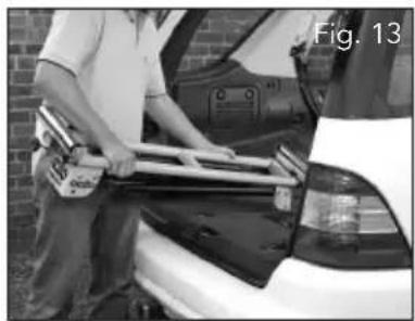
- The Mitre Saw Stand can be easily folded for convenient storage and transportation (Fig. 13).
- Simply follow the leg assembly instructions in reverse to fold up the Mitre Saw Stand.
Note: When transporting the Mitre Saw Stand in a vehicle, always tie it down to prevent movement and possible damage.
natural_image
Person applying fuel to a car, no visible text or symbolsMAINTENANCE
- Wipe away dirt and dust from the Mitre Saw Stand on a regular basis.
Note: Ozito Industries will not be responsible for any damage or injuries caused by the repair of the tool by an unauthorised person or by mishandling of the Mitre Saw Stand.
SPARE PARTS
Limited spare parts are available subject to availability. Please contact your local Bunnings Special Orders Desk to order the required spare parts.
Most common spare parts listed below
Spare Part Part No.
Star knob (pack of 2) SPMSS003-07
Knob (pack of 2) SPMSS003-12
Mitre Saw Mounts SPMSS003-25A
CONTENTS
1 x Mitre Saw Stand (MSS-003)
2 x Height adjustment knobs
2 x Mitre saw mount brackets
1 x Instruction manual
4 x Length adjustment knobs
2 x Work supports
4 x Fixing bolts, nuts & washers
OZITO INDUSTRIES PTY LTD
AUSTRALIA (Head Office)
1 - 23 Letcon Drive, Bangholme, Victoria, Australia 3175
Telephone: 1800 069 486
Facsimile: +61 3 9238 5588
Website: www.ozito.com.au
Email: enquiries@ozito.com.au
WARRANTY
YOUR WARRANTY FORM SHOULD BE RETAINED BY YOU AT ALL TIMES. IN ORDER TO MAKE A CLAIM UNDER THIS WARRANTY YOU MUST RETURN THE PRODUCT TO YOUR NEAREST BUNNINGS WAREHOUSE WITH YOUR BUNNINGS REGISTER RECEIPT. PRIOR TO RETURNING YOUR PRODUCT FOR WARRANTY PLEASE TELEPHONE OUR CUSTOMER SERVICE HELPLINE:
Australia 1800 069 486 New Zealand 0508 069 486
TO ENSURE A SPEEDY RESPONSE PLEASE HAVE THE MODEL NUMBER AND DATE OF PURCHASE AVAILABLE. A CUSTOMER SERVICE REPRESENTATIVE WILL TAKE YOUR CALL AND ANSWER ANY QUESTIONS YOU MAY HAVE RELATING TO THE WARRANTY POLICY OR PROCEDURE.
The benefits provided under this warranty are in addition to other rights and remedies which are available to you at law.
Our goods come with guarantees that cannot be excluded at law. You are entitled to a replacement or refund for a major failure and for compensation for any other reasonably foreseeable loss or damage. You are also entitled to have the goods repaired or replaced if the goods fail to be of acceptable quality and the failure does not amount to a major failure.
Generally you will be responsible for all costs associated with a claim under this warranty, however, where you have suffered any additional direct loss as a result of a defective product you may be able to claim such expenses by contacting our customer service helpline above.
2 YEAR REPLACEMENT WARRANTY
Your product is guaranteed for a period of 24 months from the original date of purchase and is intended for DIY (Do It Yourself) use only. If a product is defective it will be replaced in accordance with the terms of this warranty. Warranty excludes consumable parts, for example: adjustment knobs, brackets, work supports, bolts, nuts and washers.
WARNING
The following actions will result in the warranty being void.
• Professional, Industrial or high frequency use.
- If the tool shows signs of damage or defects caused by or resulting from abuse, accidents or alterations.
• If the tool is disassembled or tampered with in any way.
YardWorks
Australia/New Zealand (Head Office)
1-23 Letcon Drive, Bangholme, Victoria, Australia 3175
- SPECIFICATIONS - MODEL NO. MSS-003
- KNOW YOUR PRODUCT
- TABLE OF CONTENTS
- INTRODUCTION
- GENERAL SAFETY INSTRUCTIONS
- ADDITIONAL SAFETY INSTRUCTIONS FOR MITRE SAW STANDS
- ASSEMBLY
- Leg Assembly
- Fitting the Extension Bar Locking Knobs
- Fitting the Work Support Rollers
- ASSEMBLY (cont.)
- Fixing the Mitre Saw Mounts
- OPERATION
- Adjusting the Extension Bars
- Adjusting the Work Support Rollers
- Material Stops
- OPERATION (cont.)
- Attaching a Mitre Saw
- Storage and Transport
- MAINTENANCE
- SPARE PARTS
- Most common spare parts listed below
- CONTENTS
- OZITO INDUSTRIES PTY LTD
- AUSTRALIA (Head Office)
- WARRANTY
- YEAR REPLACEMENT WARRANTY
- WARNING
- The following actions will result in the warranty being void.
- YardWorks
Brand : Ozito
Model : MSS-003
Category : Saw