WRT750A - Router Black Box - Free user manual and instructions
Find the device manual for free WRT750A Black Box in PDF.


| Product Type | Router |
| Brand | Black Box |
| Model | WRT750A |
| Wi-Fi Standards | 802.11a/b/g/n/ac |
| Frequency Bands | 2.4 GHz and 5 GHz |
| Maximum Data Rate | 750 Mbps (combined) |
| Ports | 4 x Gigabit LAN, 1 x Gigabit WAN |
| USB Ports | 1 x USB 2.0 |
| Antennas | 3 external detachable antennas |
| Dimensions (W x D x H) | 7.5 x 5.0 x 1.5 inches (approx.) |
| Weight | 1.2 lbs (approx.) |
| Power Supply | 12V DC, 1.5A |
| Power Consumption | 15W (max) |
| Security | WEP, WPA/WPA2-PSK, WPA3-ready |
| Firewall | NAT, SPI, DoS protection |
| VPN Support | PPTP, L2TP, IPsec passthrough |
| Management | Web-based GUI, mobile app |
| Mounting | Desktop, wall-mountable |
| Operating Temperature | 32°F to 104°F (0°C to 40°C) |
| Certifications | FCC, CE, RoHS |
Frequently Asked Questions - WRT750A Black Box
User questions about WRT750A Black Box
0 question about this device. Answer the ones you know or ask your own.
Ask a new question about this device
Download the instructions for your Router in PDF format for free! Find your manual WRT750A - Black Box and take your electronic device back in hand. On this page are published all the documents necessary for the use of your device. WRT750A by Black Box.
USER MANUAL WRT750A Black Box
802.11ac WiFi Dual-Band Router
User Manual
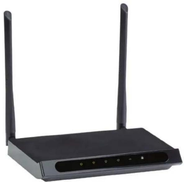
Integrates a 4-port switch, firewall, NAT router, and wireless AP in one box.
natural_image
Black wireless router device with two external antennas (no visible text or labels)Trademarks Used in this Manual
Black Box and the Double Diamond logo are registered trademarks of BB Technologies, Inc.
Any other trademarks mentioned in this manual are acknowledged to be the property of the trademark owners.
We're here to help! If you have any questions about your application or our products, contact Black Box Tech Support at 877-877-2269 or go to blackbox.com and click on "Talk to Black Box."
You'll be live with one of our technical experts in less than 60 seconds.
Federal Communications Commission and Industry Canada Radio Frequency Interference Statements
This equipment has been tested and found to comply with the limits for a Class B digital device, pursuant to part 15 of the FCC Rules. These limits are designed to provide reasonable protection against harmful interference in a residential installation. This equipment generates, uses and can radiate radio frequency energy and, if not installed and used in accordance with the instructions, may cause harmful interference to radio communications. However, there is no guarantee that interference will not occur in a particular installation. If this equipment does cause harmful interference to radio or television reception, which can be determined by turning the equipment off and on, the user is WRT750A encouraged to try to correct the interference by one or more of the following measures:
- Reorient or relocate the receiving antenna.
- Increase the separation between the equipment and receiver.
- Connect the equipment into an outlet on a circuit different from that to which the receiver is connected.
- Consult the dealer or an experienced radio/ TV technician for help.
This device complies with part 15 of the FCC Rules. Operation is subject to the following two conditions:
- This device may not cause harmful interference.
- This device must accept any interference received, including interference that may cause undesired operation.
Any changes or modifications not expressly approved by the party responsible for compliance could void the user's authority to operate the equipment.
NOTE: The manufacturer is not responsible for any radio or TV interference caused by unauthorized modifications to this equipment. Such modifications could void the user's authority to operate the equipment.
FCC RF Radiation Exposure Statement
This equipment complies with FCC RF radiation exposure limits set forth for an uncontrolled environment. This device and its antenna must not be co-located or operating in conjunction with any other antenna or transmitter.
To comply with FCC RF exposure compliance requirements, this grant is applicable to only Mobile Configurations. The antennas used for this transmitter must be installed to provide a separation distance of at least 20 cm from all persons and must not be co-located or operating in conjunction with any other antenna or transmitter.
CE Mark Warning
This is a class B product. In a domestic environment, this product may cause radio interference, in which case the user may be required to take adequate measures.
Disclaimer:
Black Box Network Services shall not be liable for damages of any kind, including, but not limited to, punitive, consequential or cost of cover damages, resulting from any errors in the product information or specifications set forth in this document and Black Box Network Services may revise this document at any time without notice.
National Restrictions
This device is intended for home and office use in all EU countries (and other countries following the EU directive 1999/5/EC) without any limitation except for the countries mentioned below:
| Country Restriction | Reason/Remark | |
| Bulgaria | None | General authorization required for outdoor use and public service. |
| France Outdoor use | limited to 10 mW e.i.r.p. within the band 2454-2483.5 MHz | Military Radiolocation use. Reframing of the 2.4 GHz band has been ongoing in recent years to allow current relaxed regulation. Full implementation planned 2012. |
| Italy | None | If used outside of own premises, general authorization is required. |
| Luxembourg | None | General authorization required for network and service supply(not for spectrum). |
| Norway | Implemented | This subsection does not apply for the geographical area within a radius of 20 km from the centre of Ny-Ålesund |
| Russian Federation | None Only for indoor applications. |
NOTE: Do not use the product outdoors in France.
Table of Contents
- Specifications....8
- Overview....10
2.1 Introduction....10
2.2 Features....10
2.3 What's Included 11
2.4 Hardware Description....11
2.4.1 Front Panel 11
2.4.2 Back Panel 13
- Installing the Router 15
3.1 System Requirements 15
3.2 Installation Environment Requirements....15
3.3 Connecting the Router 15
- Quick Installation Guide .... 17
4.1 TCP/IP Configuration 17
4.2 Quick Installation Steps....18
- Configuring the Router....29
5.1 Login 29
5.2 Status 30
5.3 Quick Setup....31
5.4 Network 31
5.4.1 WAN 31
5.4.2 LAN 38
5.4.3 MAC Clone 39
5.5 Dual Band Selection 39
5.6 Wireless 2.4 GHz 40
5.6.1 Basic Settings....40
5.6.2 WPS 42
5.6.3 Wireless Security 44
5.6.4 Wireless MAC Filtering....46
5.6.5 Wireless Advanced 48
5.6.6 Wireless Statistics 49
5.7 Wireless 5 GHz....50
5.7.1 Basic Settings....50
5.7.2 WPS....52
5.7.3 Wireless Security....54
5.7.4 Wireless MAC Filtering 56
5.7.5 Wireless Advanced....58
5.7.6 Wireless Statistics....59
5.8 Guest Network....60
5.9 DHCP....61
5.9.1 DHCP Settings 61
5.9.2 DHCP Clients List....62
5.9.3 Address Reservation 62
5.10 USB Settings....64
5.10.1 USB Mass Storage....64
5.10.2 User Accounts 64
5.10.3 Storage Sharing 66
5.10.4 FTP Server....67
5.10.5 Media Server 69
5.11 NAT 71
5.12 Forwarding....71
5.12.1 Virtual Servers....71
5.12.2 Port Triggering....73
5.12.3 DMZ 74
5.12.4 UPnP....75
5.13 Security....76
5.13.1 Basic Security 76
5.13.2 Advanced Security 77
5.13.3 Local Management....78
5.13.4 Remote Management....78
5.14 Parent Control 79
5.15 Access Control....82
5.15.1 Rule....83
5.15.2 Host 85
5.15.3 Target 86
5.15.4 Schedule 88
5.16 Advanced Routing....89
5.16.1 Static Route List 90
5.16.2 System Routing Table 91
5.17 Bandwidth Control 91
5.18 IP & MAC Binding 92
5.18.1 Binding Settings....93
5.18.2 ARP List 94
5.19 Dynamic DNS 94
5.19.1 No-ip.com DDNS....95
5.19.2 Comexe.cn DDNS 96
5.19.3 Dyndns.com DDNS 97
5.20 IPv6 97
5.20.1 IPv6 Status....98
5.20.2 IPv6 WAN 99
5.20.3 IPv6 LAN 102
5.21 System Tools....102
5.21.1 Time Settings....103
5.21.2 Diagnostics....104
5.21.3 Firmware Upgrade....105
5.21.4 Factory Defaults....106
5.21.5 Backup and Restore....106
5.21.6 Reboot 107
5.21.7 Password 107
5.21.8 System Log....108
5.21.9 Statistics....108
5.22 Logout....110
Appendix A: FAQ 111
Appendix B: Configuring the PC 115
Appendix C: Glossary.... 117
- Specifications
| Approvals | |
| Environmental Compliances RoHS2 | |
| EMI Certifications FCC | |
| Safety Certifications CE | |
| Environmental | |
| Operating Humidity 5 to 90%, noncondensing | |
| Operating Temperature 32 to +104°F (0 to 40°C) | |
| Storage Humidity 5 to 90%, noncondensing | |
| Storage Temperature -40 to +70°F (-40 to +70°C) | |
| Management | |
| Diagnostics Power, Wireless, Ethernet, Internet, USB, WPS | |
| Interfaces (4) 10/100/1000Mbps LAN Ports,(1) 10/100/1000Mbps WAN Port,(1) USB 2.0 Port | |
| IPv6 Supported | |
| Network Web base configuration utility via Ethernet | |
| Services | TCP/IP, PPPoE, DHCP, ICMP, NAT, SNTP, IGMPv3, L2TP, PPTP, IPv6, MLD |
| Security/Authentication | WEP, WPA/WPA2, WPA2-PSK/WPA-PSK |
| Performance | |
| Data Rate | 11b: 1/2/5.5/11 Mbps;11a/g: 6/9/12/18/24/36/48/54/ Mbps;11n: up to 300 Mbps;11ac: up to 450 Mbps |
| Physical | |
| Connectors/Interfaces | (4) 10/100/1000-Mbps RJ-45 LAN ports;(1) 10/100/1000-Mbps RJ-45 WAN port;(1) USB 2.0 |
| Cabling Type | 10BASE-T: UTP category 3, 4, 5 cable (maximum 328 feet [100 m]),EIA/TIA-568: 100 STP (maximum 328 feet [100 m]),100BASE-TX: UTP category 5, 5e cable (maximum 328 feet [100 m]),EIA/TIA-568: 100 STP (maximum328 feet [100 m]), 1000BASE-TX: UTP category 5, 5e cable (maximum 328 feet [100 m]),EIA/TIA-568: 100 STP (maximum 328 feet [100 m]) |
| Dimensions | 7.3"H x 1.2"W x 5.2"D (18.4 x 3.0 x 13.2 cm) |
| Indicators | (6) LEDs: Power, Wireless, Ethernet, Internet, USB, WPS |
| Ports | (1) 10/100/1000M Auto-Negotiation Internet RJ-45 port;(4) 10/100/1000M Auto-Negotiation LAN RJ45 ports supporting Auto MDI/MDIX;(1) USB port supporting storage/FTP/Media; |
| Weight | 0.5 lb. (0.2 kg) |
| Physical (continued) | |
| Wireless Antennas (2) 2.4–2.5 GHz (2 dBi), 4.9–5.825 GHz detachable omnidirectional | |
| Wireless Frequencies | 2.4–2.4835 GHz, 5.180–5.240 GHz, 5.745–5.825 GHz;NOTE: Only 2.412 to 2.462 GHz is allowed to be used in USA, which means only channels 1–11 are available for American users to choose. |
| Wireless Interface Protocol DSSS | (Direct Sequence Spread Spectrum) |
| Modulation Type 11ac: 256-QAM for OFDM;11n/g/a: QPSK, BPSK,16-QAM, 64-QAM for OFDM;11b: CCK, DQPSK, DBPSK | |
| Sensitivity Per 5 G: | 11a 6-Mbps: -91 dBm,11a 54-Mbps: -74 dBm,11ac HT20: -66 dBm,11ac HT40: -64 dBm,11ac HT80: -61 dBm;Per 2.4 G:11g 54-M:-74 dBm,11n HT20: -72 dBm,11n HT40: -69dBm |
| Power | |
| Input 100-240 VAC 50-60 Hz | |
| Output 12VDC/1.5A 18W | |
| Power Supply Type External switching power adapter | |
| Features | |
| Wireless Security WPA/WPA2, WPA-PSK/WPA2-PSK, TKIP/AES, 64/128/152-bit WEP | |
| Protocols and Standards | |
| IEEE 802.11ac, IEEE 802.11n, IEEE 802.11g, IEEE 802.11b, IEEE 802.11a, IEEE 802.11e, IEEE 802.11i, IEEE 802.1X, IEEE 802.3X, IEEE 802.3, IEEE 802.3u, IEEE 802.3ab, CSMA/CA,CSMA/CD, TCP/IP, DHCP, ICMP, NAT, PPPoE | |
2. Overview
2.1 Introduction
The Gigabit Dual Band Router - 802.11ac Wi-Fi integrates a 4-port Switch, Firewall, NAT-router and Wireless AP. The router delivers exceptional range and speed that fully meets the need of Small Office/Home Office (SOHO) networks and the users who demand higher networking performance. Your wireless connections are radio-band selectable to avoid interference in your area, and the four built-in Gigabit ports supply high-speed connection to your wired devices.
The Gigabit Dual Band Router - 802.11ac Wi-Fi provides up to 750 Mbps wireless connection with other wireless clients. The incredible speed makes it ideal for handling multiple data streams at the same time, which keeps your network stable and smooth. The performance of this 802.11ac wireless router gives you a networking experience at speeds much faster than 802.11n. It is also compatible with all IEEE 802.11n, IEEE 802.11a, IEEE 802.11b, and IEEE 802.11g products.
With multiple protection measures, including SSID broadcast control and wireless LAN 64/128-bit WEP encryption, Wi-Fi Protected Access (WPA2- PSK, WPA- PSK), as well as advanced Firewall protections, the Gigabit Dual Band Router - 802.11ac Wi-Fi provides complete data privacy.
The router offers flexible access control, so that parents or network administrators can establish restricted access policies for children or staff. It also supports Virtual Server and DMZ host for Port Triggering, so network administrators can manage and monitor the network in real-time with the remote management function.
Since the router is compatible with virtually all the major operating systems, it is very easy to manage. Quick Setup Wizard is supported and detailed instructions are provided step-by-step in this user guide. Before installing the router, look through this guide to learn the router's functions.
2.2 Features
- Complies with IEEE 802.11ac.
- Has (1) 10/100/1000M Auto-Negotiation RJ-45 WAN port and (4) 10/100/1000M Auto-Negotiation RJ-45 LAN ports, and supports Auto MDI/MDI-X.
- USB ports support storage/FTP/Media.
- Offers WPA/WPA2, WPA-PSK/WPA2-PSK authentication, TKIP/AES encryption security.
- Shares data and Internet access for users, supporting Dynamic IP/ Static IP/ PPPoE/ PPTP/ L2TP/ BigPond Internet access.
• Supports simultaneous 2.4GHz and 5GHz connections for 750Mbps of total available bandwidth. - Includes Virtual Server, Special Application, and DMZ host.
- Features UPnP, Dynamic DNS, Static Routing.
- Provides Automatic-connection and Scheduled Connection on certain time to the Internet.
- Supports static IP address distributing via built-in NAT and DHCP server.
- Offers Parent Control and Access Control.
- Connects Internet on demand and disconnects from the Internet when idle for PPPoE.
- Provides 64/128-bit WEP encryption security and wireless LAN ACL (Access Control List).
• Supports Flow Statistics. - Works with IPv6.
• Supports firmware upgrade and Web management.
2.3 What's Included
Your package should contain the following items. If anything is missing or damaged, contact Black Box Technical Support at 877-877-2269 or info@blackbox.com.
• Gigabit Dual Band Router - 802.11ac Wi-Fi
- DC Power Adapter
- Quick Installation Guide
To download this User Manual from our Web site:
- Go to www.blackbox.com
- Enter the part number in the search box.
- Click on the "Support" tab on the product page, and select the document you wish to download.
If you have any trouble accessing the Black Box site to download the manual, you can contact our Technical Support at 877-877-2269 or info@blackbox.com.
2.4 Hardware Description
2.4.1 Front Panel
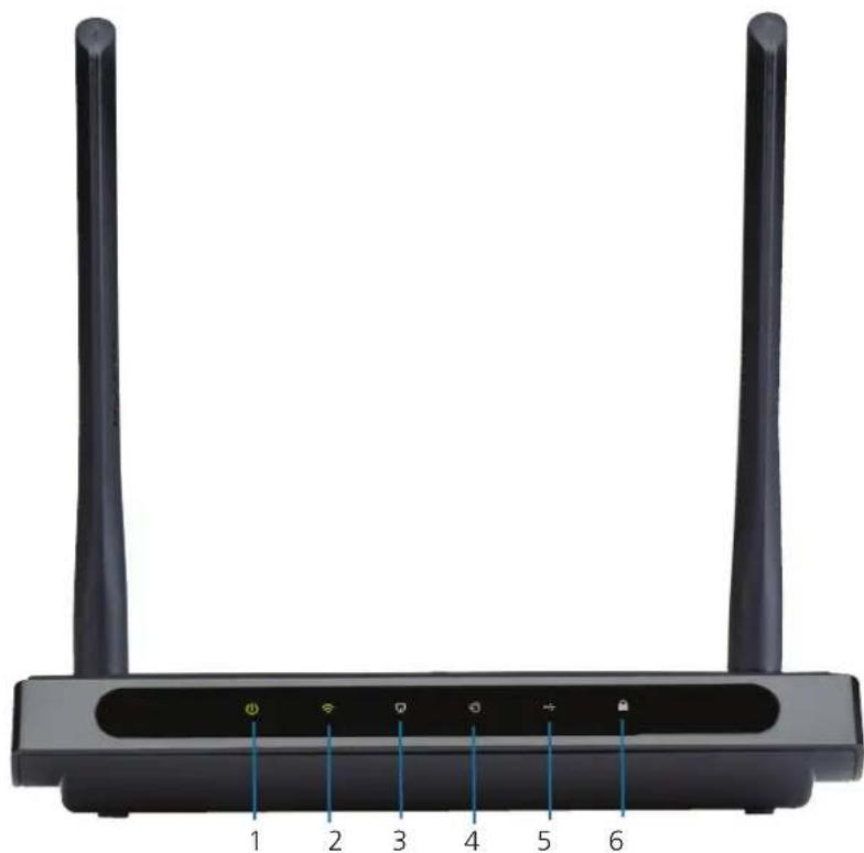
Figure 2-1 shows the front panel of the router. Table 2-1 describes its components.
natural_image
Front view of a black wireless router with two tall antennas and labeled ports (no text or symbols on the device body)Figure 2-1. Router's front panel.
The router's LEDs are located on the front panel (View from left to right).
Table 2-1. Front-panel components.
| Number in Figure 2-1 | Component Status Description | ||
| 1 Power LED Off Power is off. | |||
| On Power is on. | |||
| 2 Wireless LED Off The wireless function is disabled. | |||
| On The wireless function is enabled. The router is working on 2.4 GHz or 5 GHz or both radio bands. | |||
| 3 Ethernet LED Off No device is connected to the LAN ports. | |||
| On At least one device has connected to the LAN ports. | |||
| 4 Internet LED Off The Internet connection is not available. | |||
| On The network is available with a successful Internet connection. | |||
| 5 USB LED Off No storage device is plugged into the USB port. | |||
| Flashing A plugged-in storage device is being recognized. | |||
| On The storage device has been successfully recognized. | |||
| 6 WPS LED | Slow Flash | A wireless device is connecting to the network by WPS function. This process will last in the first 2 minutes. | |
| On A wireless device has been successfully added to the network by WPS function. | |||
| Quick Flash | A wireless device failed to be added to the network by WPS function. | ||
NOTES:
- After a device is successfully added to the network by WPS function, the WPS LED will keep on for about five minutes and then turn off.
- The router is set to work concurrently in 2.4 GHz and 5 GHz by default. To choose the working frequency, go to 5.5 Dual Band Selection.
2.4.2 Back Panel
Figure 2-2 shows the back panel of the router. Table 2-2 describes its components.
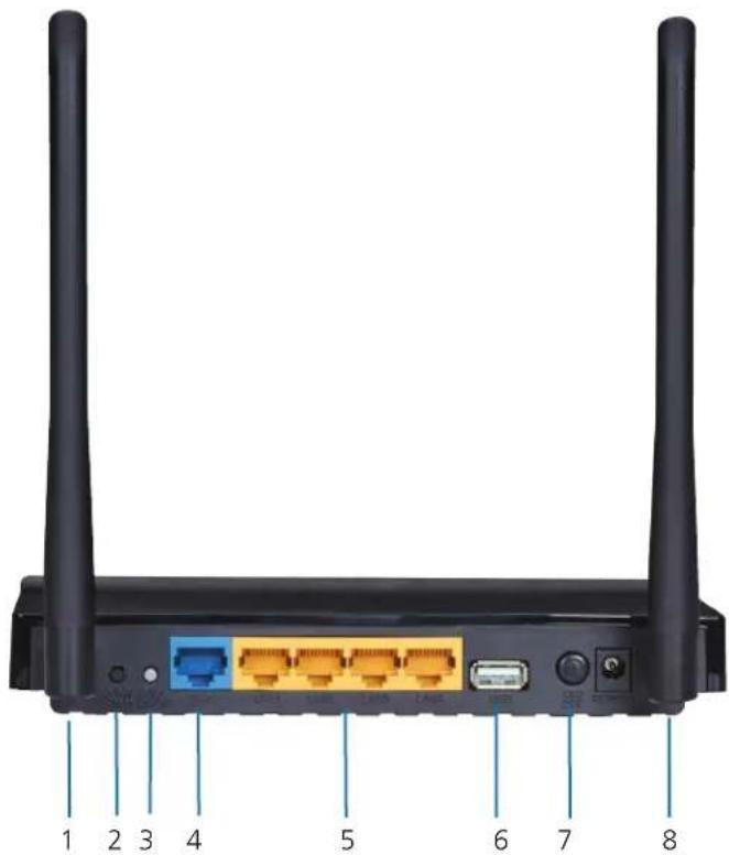
Figure 2-2. Router's back panel.
The following parts are located on the back panel (View from left to right).
Table 2-2. Back-panel components.
| Number in Figure 2-2 | Component Description | |
| 1 | WPS/Reset button | Pressing this button for less than 5 seconds enables the WPS function. If your client devices, such as wireless adapters, support Wi-Fi Protected Setup, then you can press this button to quickly establish a connection between the router and client devices and automatically configure wireless security for your wireless network. |
| Pressing this button for more than 5 seconds enables the Reset function. With the router powered on, press and hold the WPS/Reset button (approximately 8 seconds) until all LEDs are lit. And then release the button and wait for the router to reboot to its factory default settings. | ||
| 2 | Wi-Fi button | The button for turning on/off the wireless function. |
| 3 (1) RJ-45 WAN port This port is where you will connect the DSL/cable Modem, or Ethernet. | ||
| 4 (4) RJ-45 connectors for LAN Ports 1, 2, 3, 4 | These ports (1, 2, 3, 4) connect the router to the local PC(s). | |
| 5 (1) USB Type | A connector The USB port connects to a USB storage device. | |
| 6 ON/OFF switch | Powers the switch ON | or OFF. |
| 7 Barrel connector for Power | Connect the power adapter here. Use the power adapter provided with this router. | |
| 8 | (2) Wireless antennas | Receive and transmit the wireless data. |
3. Installing the Router
3.1 System Requirements
- Broadband Internet Access Service (DSL/Cable/Ethernet)
- One DSL/Cable Modem that has an RJ-45 connector (not necessary if the router is connected directly to the Ethernet).
• PCs with a working Ethernet Adapter and an Ethernet cable with RJ-45 connectors. - TCP/IP protocol on each PC.
- Web browser, such as Microsoft Internet Explorer, Mozilla Firefox, or Apple Safari.
3.2 Installation Environment Requirements
- Place the router in a well-ventilated place far from any heater or heating vent.
- Avoid direct light (such as sunlight).
- Keep at least 2 inches (5 cm) of clear space around the router.
- Comply with operating temperature and humidity requirements:
- Operating Temperature: 32 to 104°F (0 to 40°C)
- Operating Humidity: 10–90% relative humidity, non-condensing
3.3 Connecting the Router
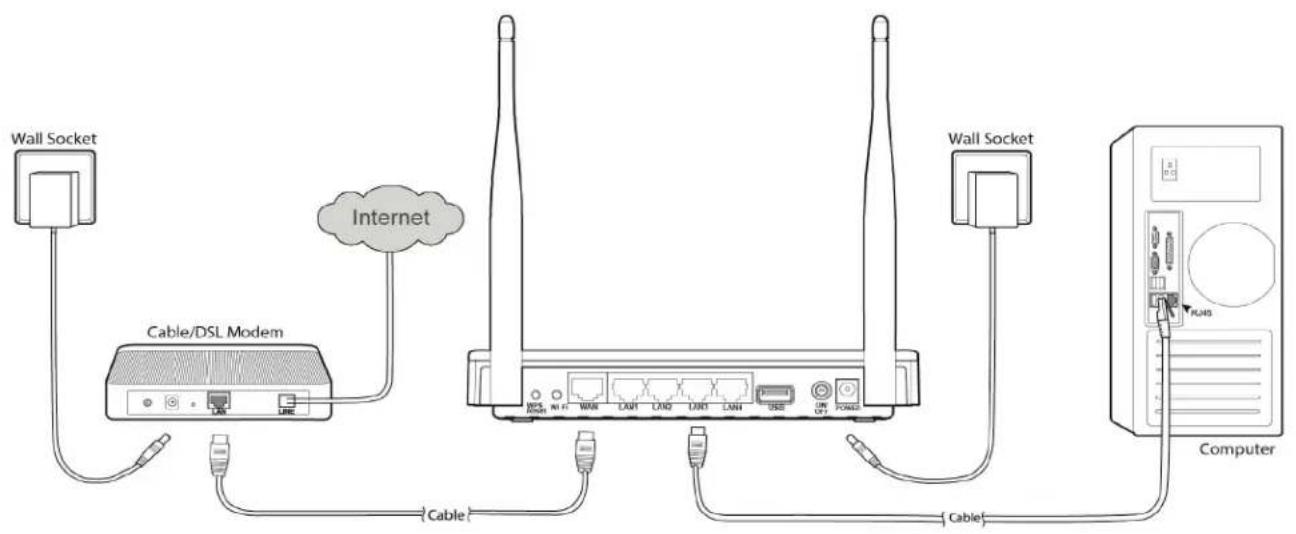
Before installing the router, make sure your PC is connected to the Internet through the broadband service successfully. If there is any problem, contact your ISP. After that, install the router according to the following steps. Don't forget to pull out the power plug and keep your hands dry.
- Power off your modem (if the modem has a backup battery, remove it, too.), and disconnect your existing router if you have one.
- Connect the WAN port on your router to the modem's LAN port with an Ethernet cable.
- Connect your computer to one of the LAN ports labeled 1–4 on the router with an Ethernet cable.
- Power on the modem and wait for 2 minutes.
- Plug the provided power adapter into the POWER jack and the other end into a standard electrical wall socket. Press the ON/OFF button to power on the router.
CAUTION: Before you power on the router, make sure your computer is NOT connected to any other wireless network.
flowchart
graph TD
    A["Wall Socket"] -->|Cable| B["Cable/DSL Modem"]
    B -->|Cable| C["Internet"]
    C -->|Cable| D["Computer"]
    D -->|Cable| E["Wall Socket"]
    style A fill:#f9f,stroke:#333
    style B fill:#ccf,stroke:#333
    style C fill:#cfc,stroke:#333
    style D fill:#fcc,stroke:#333
    style E fill:#ffc,stroke:#333
Figure 3-1. Hardware installation.
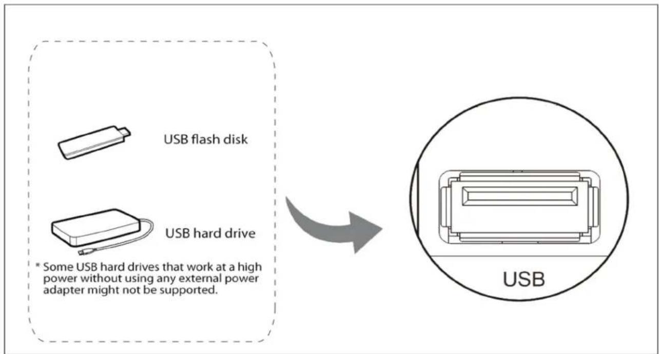
Figure 3-2. USB installation.
NOTE: If you want to use the router to share files, plug the USB storage device into the USB port.
4. Quick Installation Guide
This chapter will show you how to configure the basic functions of your Gigabit Dual Band Router - 802.11ac Wi-Fi using the Quick Setup Wizard within minutes.
4.1 TCP/IP Configuration
The default IP address of the router is 192.168.1.1 and the default Subnet Mask is 255.255.255.0. These values can be changed as you desire. In this guide, we use all the default values for description.
Connect the local PC to the LAN ports of the router and then you can configure the IP address for your PC by the following method: Set up the TCP/IP Protocol in "Obtain an IP address automatically" mode on your PC. If you need instructions for how to do this, refer to Appendix B: Configuring the PC. Then the built-in DHCP server will assign IP address for the PC.
Next, run the Ping command in the command prompt to verify the network connection between your PC and the router. The following example is in Windows XP OS.
Open a command prompt, type ping 192.168.1.1, and then press Enter.
- If the result displayed is similar to Figure 3-1, the connection between your PC and the router has been established well.
Pinging 192.168.1.1 with 32 bytes of data:
Reply from 192.168.1.1: bytes=32 time<1ms TTL=64
Reply from 192.168.1.1: bytes=32 time<1ms TTL=64
Reply from 192.168.1.1: bytes=32 time<1ms TTL=64
Reply from 192.168.1.1: bytes=32 time<1ms TTL=64

Ping statistics for 192.168.1.1:
    Packets: Sent = 4, Received = 4, Lost = 0 (0% loss),
Approximate round trip times in milli-seconds:
    Minimum = 0ms, Maximum = 0ms, Average = 0ms
Figure 4-1. Screen showing successful ping results.
- If the result displayed is similar to Figure 3-2, the connection between your PC and the router failed.
Pinging 192.168.1.1 with 32 bytes of data:

Request timed out.

Request timed out.

Request timed out.

Request timed out.

Ping statistics for 192.168.1.1:
    Packets: Sent = 4, Received = 0, Lost = 4 (100% loss),
Figure 4-2. Screen showing failed ping results.
To check the connection, follow these steps:
- Is the connection between your PC and the router correct?
NOTE: The Ethernet LED on the router and LEDs on your PC's adapter should be lit.
- Is the TCP/IP configuration for your PC correct?
NOTE: If the router's IP address is 192.168.1.1, your PC's IP address must be within the range of 192.168.1.2–192.168.1.254
- Is the default LAN IP of the router correct?
NOTE: If the LAN IP of the modem connected with your router is 192.168.1.x, the default LAN IP of the router will automatically switch from 192.168.1.1 to 192.168.0.1 to avoid IP conflict.
4.2 Quick Installation Steps
With a Web-based utility, it is easy to configure and manage the Gigabit Dual Band Router - 802.11ac Wi-Fi. The Web-based utility can be used on any Windows, Macintosh, or UNIX OS with a Web browser, such as Microsoft Internet Explorer, Mozilla Firefox, or Apple Safari.
- To access the configuration utility, open a web-browser and type in the default IP address http://192.168.1.1 in the address field.

Figure 4-3. Log in to the router.
After a moment, a login window will appear, similar to Figure 4-4. Enter "admin" for the User Name and Password, both in lower case letters. Then click the Login button or press the Enter key.
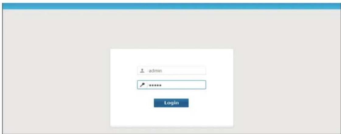
Figure 4-4. Windows login.
NOTE: If the above screen does not pop up, it means that your Web-browser has been set to a proxy. Go to Tools menu>Internet Options>Connections>LAN Settings. In the screen that appears, cancel the Using Proxy checkbox, and click OK.
- After successful login, the Quick Setup page will appear for you to quickly configure your router.
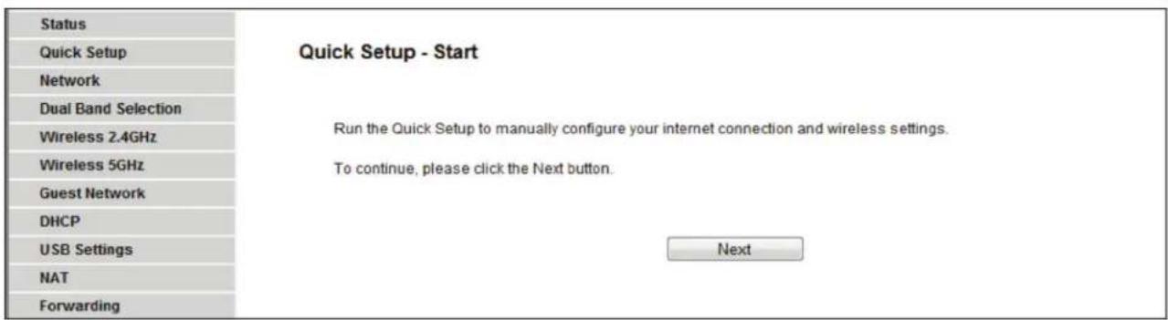
Figure 4-5. Quick setup screen.
- Click Next, and then WAN Connection Type page will appear.
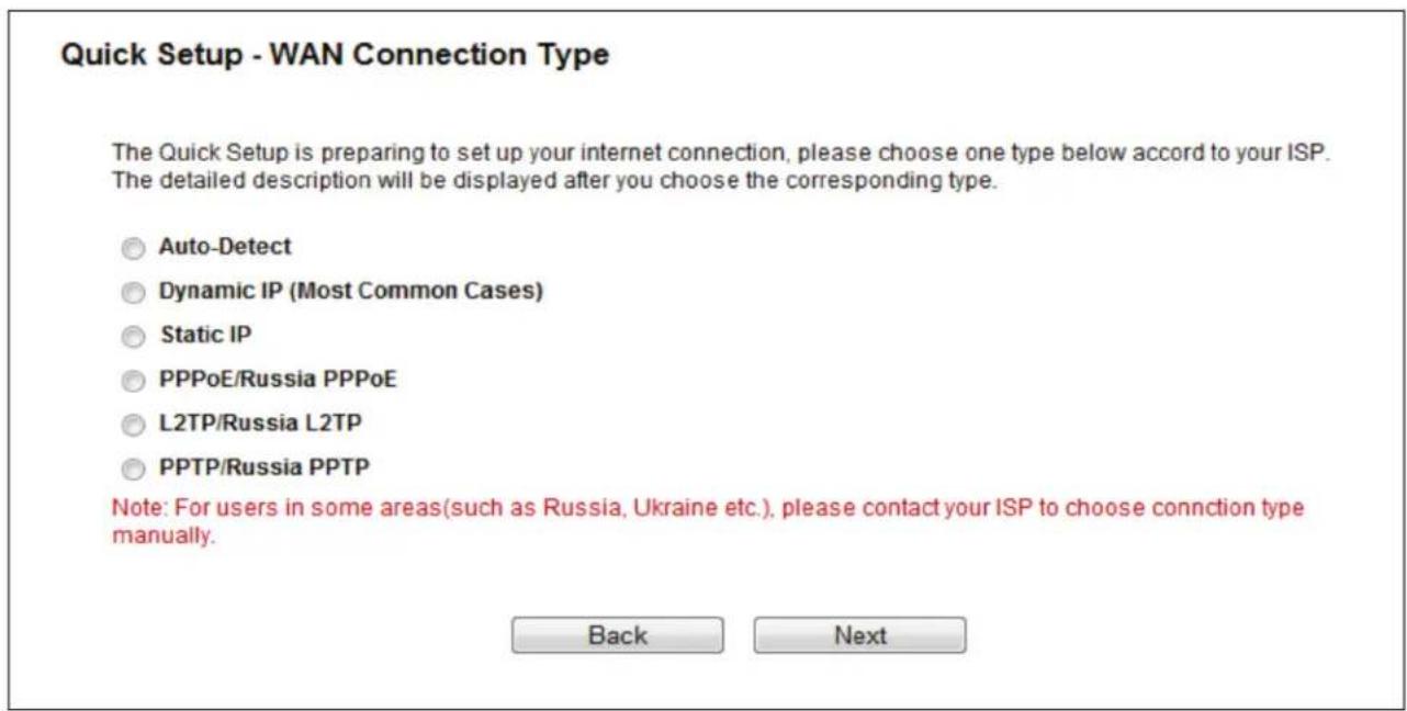
Figure 4-6. WAN Connection Type.
The router provides an Auto-Detect function and supports five types of WAN connection: Dynamic IP, Static IP, PPPoE/Russian PPPoE, L2TP/Russian L2TP, and PPTP/Russian PPTP. We recommend using the Auto-Detect function. If you are sure of what kind of connection type your ISP provides, you can select the very type and click "Next" to continue configuring.
- If you select Auto-Detect, the router will automatically detect the connection type your ISP provides. Make sure the cable is securely plugged into the WAN port before detection. The appropriate configuration page will be displayed when an active Internet service is successfully detected by the router.
NOTE: If Auto-Detect fails, you can select the connection type your ISP provides and follow the procedures below to continue configuring the router.
- If the connection type detected is Dynamic IP, the MAC Clone page will appear. In most cases, you don't need to clone the MAC address. Select "No, I do NOT need to clone MAC address" and then click "Next." If you need to clone the file, select "Yes, I need to clone MAC address" and then click "Next."
Quick Setup - MAC Clone
MAC(Media Access Control) address is a unique identifier that identifies your computer or device in the network. Some of the ISPs may register the MAC address of your computer which firstly connects to their services, and would not allow the Internet connection for any new computer or router. TP-LINK router can help you to "clone" or replicate the registered MAC address of your first computer.
In most of the cases, there is no need to clone the MAC address. But if you can't get the Internet connection after Quick Setup, please run it again and clone the MAC address for a try.
No, I do NOT need to clone MAC address.
☐ YES, I need to clone MAC address.
Note: please make sure your current computer is the one initially connected to your router or ISP's device.
Back
Next
Figure 4-7. Quick Setup—MAC Clone.
- If the connection type detected is Static IP, the next screen will appear. Configure the following parameters and then click "Next" to continue.
Quick Setup - Static IP
Please enter the basic parameter settings provided by your ISP. If basic parameters are unknown, please contact ISP.
IP Address: 0.0.0.0
Subnet Mask: 0.0.0.0
Gateway: 0.0.0.0
Primary DNS Server: 0.0.0.0
Secondary DNS Server: 0.0.0.0
(optional)
Back
Next
Figure 4-8. Quick Setup—Static IP.
- IP Address—This is the WAN IP address external users see on the Internet (including your ISP). Your ISP will provide the IP address you need to enter here. Enter the IP address into the field.
-
Subnet Mask—The Subnet Mask is used for the WAN IP address. Your ISP will provide the subnet mask, which is usually 255.255.255.0.
-
Gateway—Your ISP will provide the Gateway address which is the ISP server's address. Enter the gateway IP address into the box if required.
- DNS Server (Optional) Enter the DNS Server IP address into the box if required.
- Secondary DNS Server Optional) If your ISP provides another DNS server, enter it into this field.
- If the connection type detected is PPPoE/Russia PPPoE, the next screen will appear. Configure the following parameters and then click "Next" to continue.
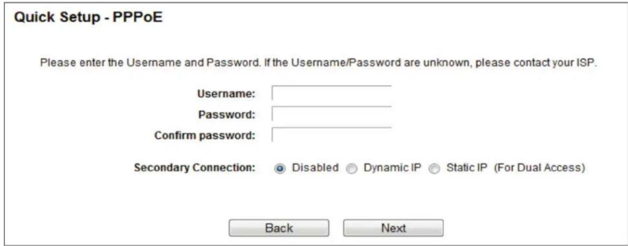
Figure 4-9. Quick Setup—PPPoE/Russia PPPoE.
- User Name/Password—Enter the User Name and Password provided by your ISP. These fields are case-sensitive. If you have difficulty with this process, contact your ISP.
- Confirm Password—Enter the password again to make sure that the password is correct.
- If your connection type is L2TP/ Russia L2TP, select L2TP/Russia L2TP in Figure 4-6 and the next screen will appear as shown in Figure 4-10. Configure the following parameters and then click "Next" to continue.
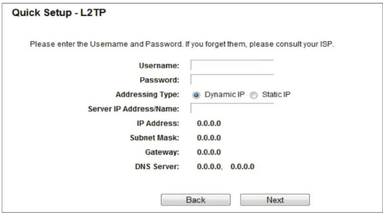
Figure 4-10. Quick Setup—L2TP/Russia L2TP.
- Username/Password—Enter the Username and Password provided by your ISP. These fields are case-sensitive. If you have difficulty with this process, contact your ISP.
Select Static IP if the IP Address/ Subnet Mask/ Gateway and DNS server address have been provided by your ISP. Then please enter server IP address or domain name provided by your ISP, and also enter the corresponding parameters.
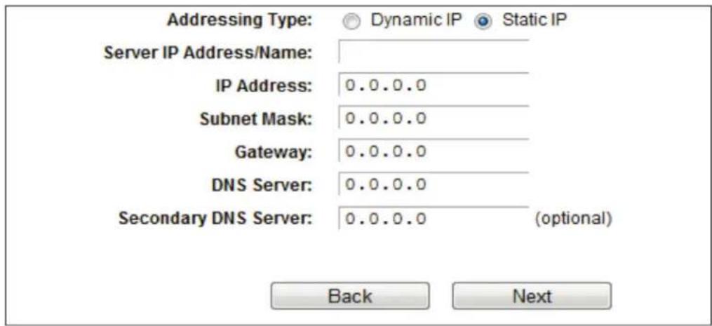
Figure 4-11. Static IP screen.
Select Dynamic IP if none of the above parameters are provided. Then you just need to enter server IP address or domain name provided by your ISP.

Figure 4-12. Dynamic IP screen.
- If your connection type is PPTP/Russia PPTP, select PPTP/Russia PPTP in Figure 4-6 and the next screen will appear as shown in Figure 4-13. Configure the following parameters and then click "Next" to continue.
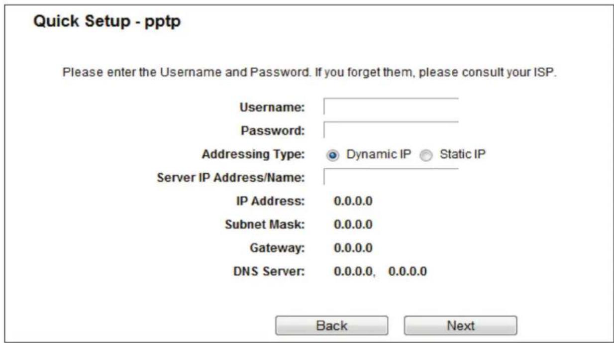
Figure 4-13. Quick Setup—PPTP/Russia PPTP.
- Username/Password—Enter the Username and Password provided by your ISP. These fields are case-sensitive. If you have difficulty with this process, contact your ISP.
Select Static IP if the IP Address/ Subnet Mask/ Gateway and DNS server address have been provided by your ISP. Then enter the server IP address or domain name provided by your ISP, and also enter the corresponding parameters.
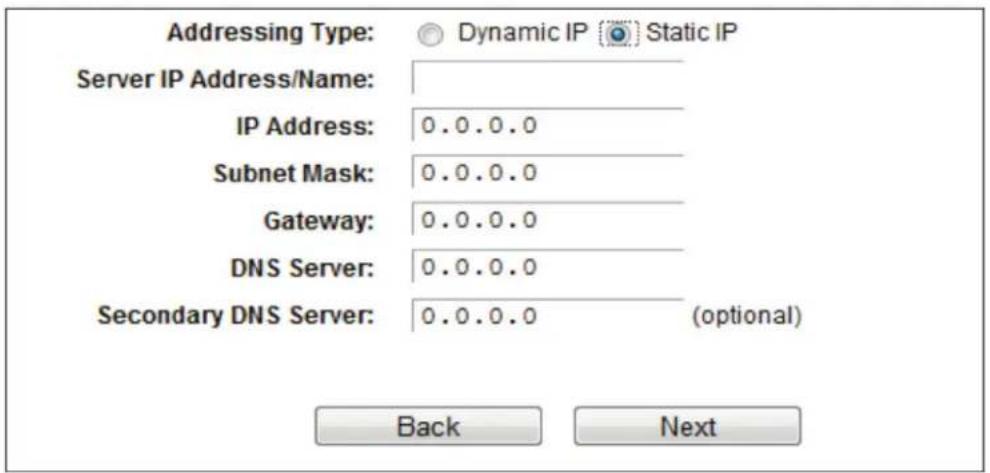
Figure 4-14. Static IP screen.
Select Dynamic IP if none of the above parameters are provided. Then you just need to enter server IP address or domain name provided by your ISP.

Figure 4-15. Dynamic IP screen.
- After you select the WAN Connection Type, the Dual Band Selection page will appear. Here we take "2.4 GHz and 5 GHz" for example. Click "Next" to continue.
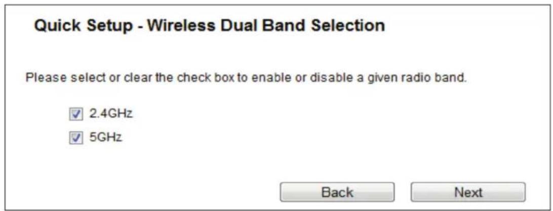
Figure 4-16. Quick Setup—Dual Band Selection.
- 2.4 GHz - You can use the 2.4 GHz band to connect to many classic wireless devices like gaming consoles, laptops, DVRs, etc.
-
5 GHz—This band is less crowded and is used for time-sensitive music, video streaming or gaming. Using this band can avoid interference with 2.4GHz networks or noisy devices like cordless phones and microwave ovens.
-
Configure the basic parameters for 2.4 GHz wireless network in the following screen as shown in Figure 3 13, and then click Next.
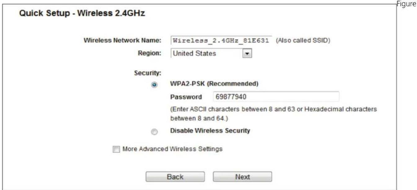
4-17. Quick Setup—Wireless 2.4 GHz.
- Wireless Network Name—Also called the SSID (Service Set Identification). Enter a value of up to 32 characters. The same name must be assigned to all wireless devices in your network. The default SSID is set to be Wireless_2.4GHz_XXXXXX. This value is case-sensitive. For example, TEST is NOT the same as test.
- Region—Select your region from the drop-down list. This field specifies the region where the wireless function of the router can be used. It may be illegal to use the wireless function of the router in a region other than one of those specified in this field. If your country or region is not listed, please contact your local government agency for assistance.
NOTE: Limited by local law regulations, version for North America does not have region selection option.
- Security—
- Enable Security (WPA-PSK/WPA2-PSK),—It's selected by default, with the default PSK password the same as the default PIN code.
- Disable Wireless Security—The wireless security function can be enabled or disabled. If disabled, the wireless stations will be able to connect the router without encryption.
The above settings are only for basic wireless parameters. For advanced settings, check "More Advanced Wireless Settings" and then you can set the following parameters.
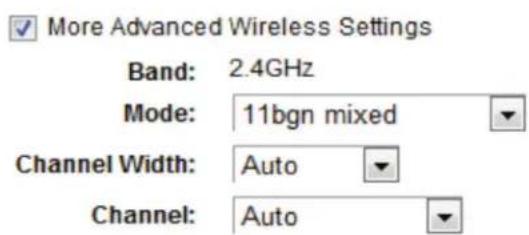
Figure 4-18. More Advanced Wireless Settings screen.
- Band - This field displayed the operating frequency being configured.
- Mode - This field determines the wireless mode which the router works on.
- 11bg mixed —Select if you are using both 802.11b and 802.11g wireless clients.
- 11bgn mixed—Select if you are using a mix of 802.11b, 11g, and 11n wireless clients.
- Channel Width—Select any channel width from the drop-down list. The default setting is "Auto," which can adjust the channel width for your clients automatically.
- Channel—This field determines which operating frequency will be used. It is not necessary to change the wireless channel unless you notice interference problems with another nearby access point. If you select "Auto", then the AP will select the best channel automatically.
- Configure the basic parameters for 5 GHz wireless network in the following screen, and then click Next.
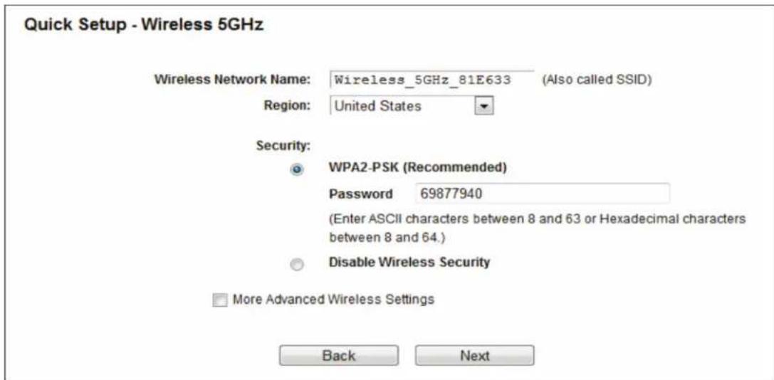
Figure 4-19. Quick Setup—Wireless 5 GHz.
- Wireless Network Name—Also called the SSID (Service Set Identification). Enter a value of up to 32 characters. The same name must be assigned to all wireless devices in your network. The default SSID is set to be Wireless_5GHz_XXXXXX. This value is case-sensitive. For example, TEST is NOT the same as test.
- Region—Select your region from the drop-down list. This field specifies the region where the wireless function of the router can be used. It may be illegal to use the wireless function of the router in a region other than one of those specified in this field. If your country or region is not listed, contact your local government agency for assistance.
NOTE: Limited by local law regulations, version for North America does not have region selection option.
- Security
- Enable Security (WPA-PSK/WPA2-PSK)—It's selected by default, with the default PSK password the same as the default PIN code.
- Disable Security—The wireless security function can be enabled or disabled. If disabled, the wireless stations will be able to connect the router without encryption.
The above settings are only for basic wireless parameters. For advanced settings, check "More Advanced Wireless Settings" and then you can set the following parameters.
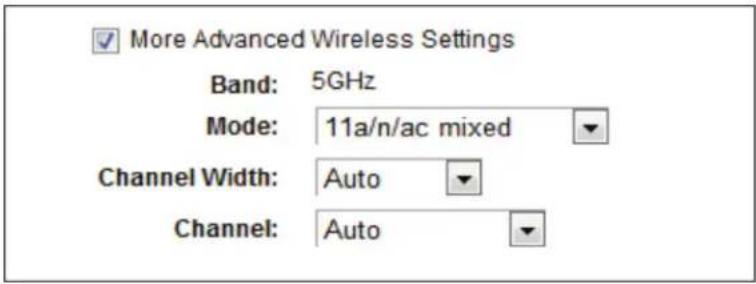
Figure 4-20. More Advanced Wireless Settings page.
- Band—This field displayed the operating frequency being configured.
- Mode—This field determines the wireless mode that the router works in.
- 11an mixed—Select if you are using both 802.11a and 802.11n wireless clients.
- 11a/n/ac mixed—Select if you are using 802.11a, 802.11n and 802.11ac wireless clients.
- Channel Width—Select any channel width from the drop-down list. The default setting is "Auto," which can adjust the channel width for your clients automatically.
- Channel—This field determines which operating frequency will be used. It is not necessary to change the wireless channel unless you notice interference problems with another nearby access point. If you select "Auto," then the AP will select the best channel automatically.
- Confirm the parameters and click the "Save" button to make the settings take effect.
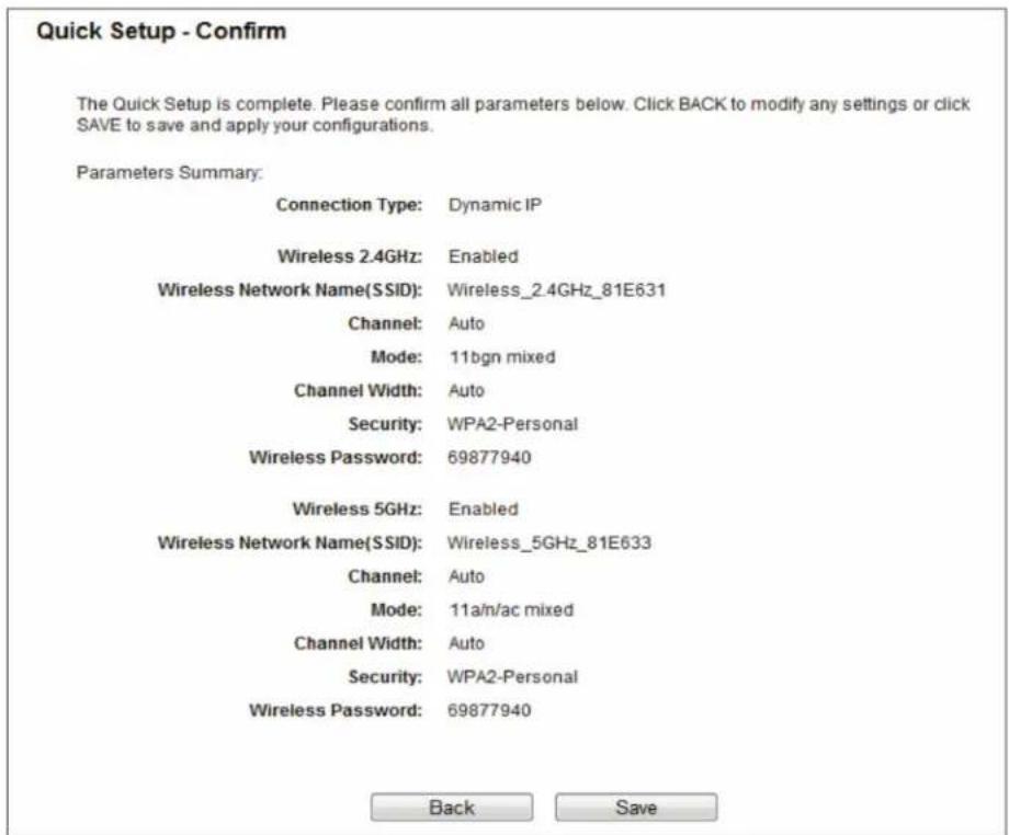
Figure 4-21. Quick Setup—Confirm.
- Click the Finish button to complete the Quick Setup.
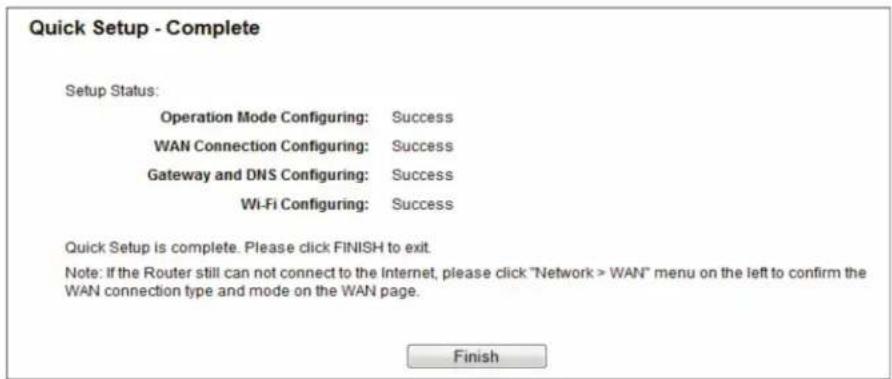
Figure 4-22. Quick Setup—Finish.
Chapter 5. Configuring the Router
This chapter will show each key function of the Web page and its configuration method.
To access the configuration utility, open a web-browser and type in the default address http://192.168.1.1 in the address field of the browser.
After a moment, a login window will appear. Enter admin for the User Name and Password, both in lower case letters. Then click Login or press Enter.
5.1 Login
After your successful login, you will see the main menus on the left of the Web-based utility. On the right, there are the corresponding explanations and instructions.
| Status |
| Quick Setup |
| Network |
| Dual Band Selection |
| Wireless 2.4GHz |
| Wireless 5GHz |
| Guest Network |
| DHCP |
| USB Settings |
| NAT |
| Forwarding |
| Security |
| Parent Control |
| Access Control |
| Advanced Routing |
| Bandwidth Control |
| IP & MAC Binding |
| Dynamic DNS |
| IPv6 |
| System Tools |
| Logout |
Figure 5-1. Main menus.
Detailed explanations for each Web page's key function are listed below.
5.2 Status
The Status page provides the current status information about the router. All information is read-only.
| Status | |
| Firmware Version: 0.9.1 0.9 v0032.0 Build 140815 Rel.66631n Hardware Version: | |
| LAN | |
| MAC Address: | |
| IP Address: 192.168.1.1 | |
| Subnet Mask: 255.255.255.0 | |
| Wireless 2.4GHz | |
| Wireless Radio: Enabled | |
| Name(SSID): Wireless_2.4GHz_81E631 Mode: 11bgn mixed Channel: Auto(Channel 4) Channel Width: Auto MAC Address: | |
| WDS Status: Disabled | |
| Wireless 5GHz | |
| Wireless Radio: Disabled | |
| Name(SSID): Wireless_5GHz_81E633 Mode: 11a/n/ac mixed Channel: Auto(Channel 40) Channel Width: Auto MAC Address: | |
| WDS Status: Disabled | |
| WAN | |
| MAC Address: | |
| IP Address: 0.0.0.0(Dynamic IP) | |
| Subnet Mask: 0.0.0.0 | |
| Default Gateway: 0.0.0.0 | |
| DNS Server: 0.0.0.0 0.0.0.0 | |
| System Up Time: 0 day(s) 00:20:43 Refresh | |
Figure 5-2. Status screen.
5.3 Quick Setup
Please refer to Section 4.2, Quick Installation Steps.
5.4 Network
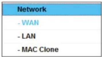
Figure 5-3. Network menu.
There are three submenus under the Network menu (shown in Figure 5-2): WAN, LAN, and MAC Clone. Click any of them, and you will be able to configure the corresponding function.
5.4.1 WAN
Choose menu "Network->WAN," then you can configure the IP parameters of the WAN on the screen below.
- If your ISP provides DHCP service, choose Dynamic IP type, and the router will automatically get IP parameters from your ISP. You can see the page as follows:
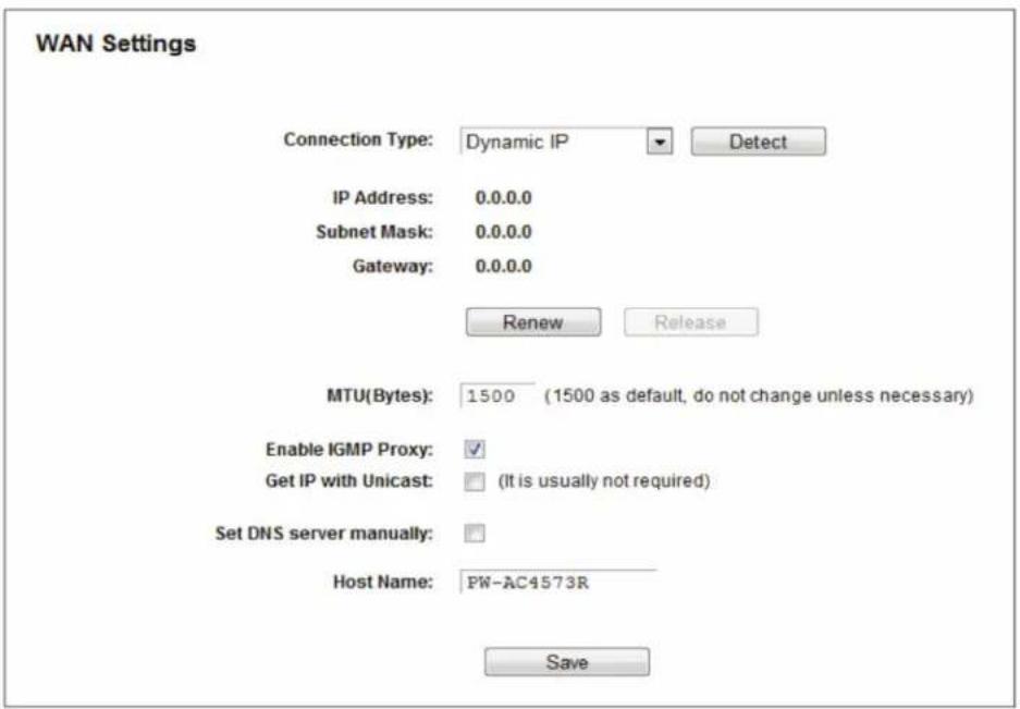
Figure 5-4. WAN—Dynamic IP.
This page displays the WAN IP parameters assigned dynamically by your ISP, including IP address, Subnet Mask, Default Gateway, etc. Click the Renew button to renew the IP parameters from your ISP. Click the Release button to release the IP parameters.
If you want to do some advanced configurations, click the Advanced button.
- MTU (Bytes)—The normal MTU (Maximum Transmission Unit) value for most Ethernet networks is 1500 bytes. We recommend that you do not change the default MTU size unless required by your ISP.
- Enable IGMP Proxy—IGMP (Internet Group Management Protocol) is used to manage multicasting on TCP/IP networks. Some ISPs use IGMP to perform remote configuration for client devices, such as the modem router. The default value is enabled, and if you are not sure, please contact your ISP or just leave it.
- Get IP with Unicast—A few ISPs' DHCP servers do not support the broadcast applications. If you cannot get the IP Address normally, you can choose this option. (It is rarely required.)
- Set DNS server manually—If your ISP gives you one or two DNS addresses, select "Set DNS server manually" and enter the primary and secondary addresses into the correct fields. Otherwise, the DNS servers will be assigned automatically from your ISP.
NOTE: If you find an error when you go to a website after entering the DNS addresses, it is likely that your DNS servers are set up improperly. You should contact your ISP to get DNS server addresses.
- Host Name—This option specifies the Host Name of the router.
Click the Save button to save your settings.
- If your ISP provides a static or fixed IP Address, Subnet Mask, Gateway, and DNS setting, select Static IP. The Static IP settings page will appear.
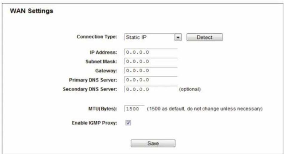
Figure 5-5. WAN—Static IP.
- IP Address—Enter the IP address in dotted-decimal notation provided by your ISP.
- Subnet Mask—Enter the subnet Mask in dotted-decimal notation provided by your ISP; usually it is 255.255.255.0.
- Gateway (Optional)—Enter the gateway IP address in dotted-decimal notation provided by your ISP.
- Primary DNS Server/Secondary DNS Server (Optional) — Enter one or two DNS addresses in dotted-decimal notation provided by your ISP.
- MTU (Bytes)—The normal MTU (Maximum Transmission Unit) value for most Ethernet networks is 1500 Bytes. Do not change the default MTU size unless required by your ISP.
- Enable IGMP Proxy—IGMP (Internet Group Management Protocol) is used to manage multicasting on TCP/IP networks. Some ISPs use IGMP to perform remote configuration for client devices, such as the modem router. The default value is enabled, and if you are not sure, contact your ISP or just leave it.
Click the Save button to save your settings.
- If your ISP provides a PPPoE connection, select the PPPoE/Russia PPPoE option. Enter the following parameters:
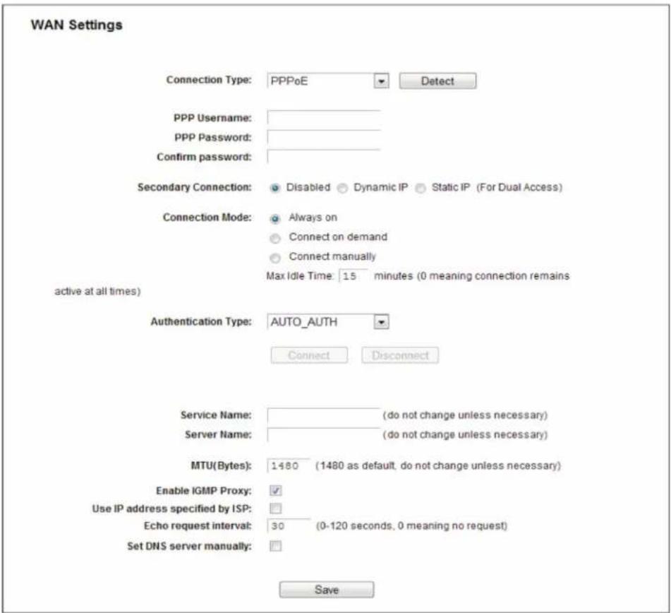
Figure 5-6. WAN—PPPoE.
- PPP Username/PPP Password —Enter the User Name and Password provided by your ISP. These fields are case-sensitive.
- Secondary Connection—It's available only for a PPPoE connection. If your ISP provides an extra connection type such as Dynamic/Static IP to connect to a local area network, then you can check the radio button of Dynamic/Static IP to activate this secondary connection.
- Disabled—The Secondary Connection is disabled by default, so there is PPPoE connection only. This is recommended.
- Dynamic IP—You can check this radio button to use Dynamic IP as the secondary connection to connect to the local area network provided by your ISP.
- Static IP—You can check this radio button to use Static IP as the secondary connection to connect to the local area network provided by your ISP.
- Connection Mode—choose the Internet connection mode.
- Always on—In this mode, the Internet connection will be active all the time.
- Connect on Demand—In this mode, the Internet connection can be terminated automatically after a specified inactivity period (Max Idle Time) and be re-established when you attempt to access the Internet again. If you want your Internet connection to stay active all the time, enter "0" in the Max Idle Time field. Otherwise, enter the number of minutes to elapse before your Internet access disconnects.
- Connect Manually—You can click the Connect/Disconnect button to connect/disconnect immediately. This mode also supports the Max Idle Time function as Connect on Demand mode. The Internet connection can be disconnected automatically after a specified inactivity period and re-established when you attempt to access the Internet again.
Click the Connect button to connect immediately. Click the Disconnect button to disconnect immediately.
CAUTION: Sometimes the connection cannot be terminated even though you specify a Max Idle Time, because some applications are visiting the Internet continually in the background.
- Service Name/Server Name—The service name and server name should not be configured unless you are sure it is necessary for your ISP. In most cases, leaving these fields blank will work.
- MTU(Bytes)—The default MTU size is "1480" bytes, which is usually fine. Do not change the default MTU Size unless required by your ISP.
- Enable IGMP Proxy—IGMP (Internet Group Management Protocol) is used to manage multicasting on TCP/IP networks. Some ISPs use IGMP to perform remote configuration for client devices, such as the modem router. The default value is enabled. If you are not sure that your network does this, contact your ISP or just leave it.
- ISP Specified IP Address—If your ISP does not automatically assign IP addresses to the router during login, click the "Use IP address specified by ISP" check box and enter the IP address provided by your ISP in dotted-decimal notation.
- Echo request interval—The router will detect Access Concentrator online at every interval. The default value is "0". You can input the value between "0" and "120". The value "0" means no detect.
- DNS/Secondary DNS—If your ISP does not automatically assign DNS addresses to the router during login, please click "Set DNS server manually" check box and enter the IP address of your ISP's primary DNS server. If a secondary DNS server address is available, enter it as well.
Click the Save button to save your settings.
- If your ISP provides BigPond Cable (or Heart Beat Signal) connection, select BigPond Cable. Enter the following parameters:
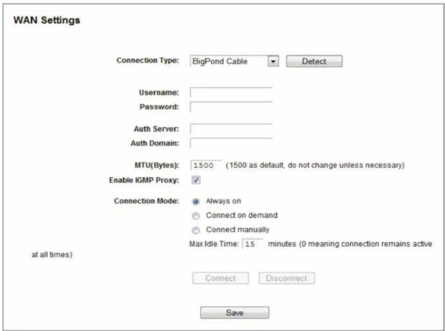
Figure 5-7. WAN—BigPond Cable.
- Username/Password—Enter the User Name and Password provided by your ISP. These fields are case-sensitive.
- Auth Server—Enter the authenticating server IP address or host name.
- Auth Domain—Type in the domain suffix server name based on your location.
For example:
NSW / ACT - nsw.bigpond.net.au
VIC / TAS / WA / SA / NT - vic.bigpond.net.au
QLD - qld.bigpond.net.au
- MTU (Bytes)—The normal MTU (Maximum Transmission Unit) value for most Ethernet networks is 1500 Bytes. Do not change the default MTU value unless required by your ISP.
- Enable IGMP Proxy—IGMP (Internet Group Management Protocol) is used to manage multicasting on TCP/IP networks. Some ISPs use IGMP to perform remote configuration for client devices, such as the modem router. The default value is enabled, and if you are not sure, contact your ISP or just leave it.
- Connection Mode—choose the Internet connection mode.
- Always on—In this mode, the Internet connection will be active all the time.
- Connect on Demand—In this mode, the Internet connection can be terminated automatically after a specified inactivity period (Max Idle Time) and be re-established when you attempt to access the Internet again. Enter the number of minutes you want to elapse before your Internet access disconnects.
- Connect Manually—You can click the Connect/Disconnect button to connect/disconnect immediately. This mode also supports the Max Idle Time function as Connect on Demand mode. The Internet connection can be disconnected automatically after a specified inactivity period and re-established when you attempt to access the Internet again.
Click the Connect button to connect immediately. Click the Disconnect button to disconnect immediately.
CAUTION: Sometimes the connection cannot be terminated even though you specify a Max Idle Time, because some applications are visiting the Internet continually in the background.
Click the Save button to save your settings.
- If your ISP provides L2TP connection, please select L2TP option. And you should enter the following parameters:
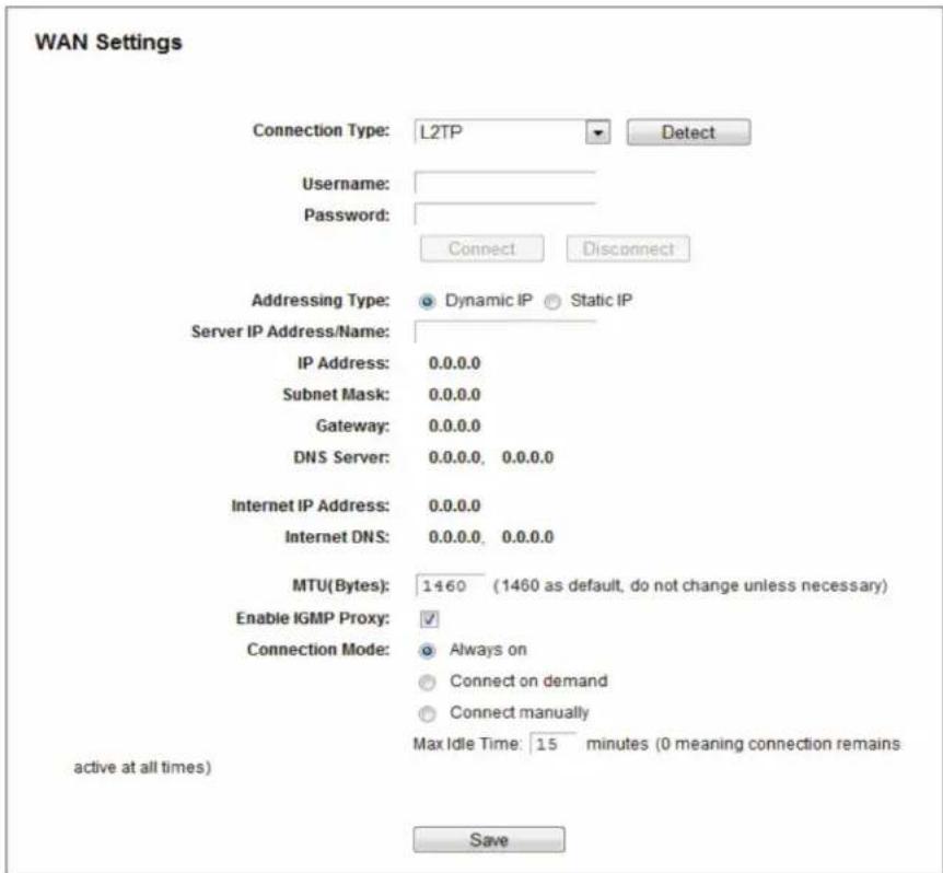
Figure 5-8. WAN—L2TP/Russia L2TP.
- Username/Password—Enter the User Name and Password provided by your ISP. These fields are case-sensitive.
- Addressing Type—Choose the addressing type given by your ISP, either Dynamic IP or Static IP. Click the Connect button to connect immediately. Click the Disconnect button to disconnect immediately.
- MTU (Bytes)—The default MTU size is "1460" bytes, which is usually fine. Do not change the default MTU Size unless required by your ISP.
- Enable IGMP Proxy—IGMP (Internet Group Management Protocol) is used to manage multicasting on TCP/IP networks. Some ISPs use IGMP to perform remote configuration for client devices, such as the modem router. The default value is enabled, and if you are not sure, contact your ISP or just leave it.
- Connection Mode—Choose the Internet connection mode.
- Always on—In this mode, the Internet connection will be active all the time.
- Connect on Demand—You can configure the router to disconnect from your Internet connection after a specified period of inactivity (Max Idle Time). If your Internet connection has been terminated due to inactivity, Connect on Demand enables the router to automatically re-establish your connection as soon as you attempt to access the Internet again. If you wish to activate Connect on Demand, check the radio button. If you want your Internet connection to remain active at all times, enter 0 in the Max Idle Time field. Otherwise, enter the number of minutes you want to elapse before your Internet connection terminates.
- Connect Manually—You can configure the router to connect or disconnect manually. After a specified period of inactivity (Max Idle Time), the router will disconnect from your Internet connection, and you will not be able to re-establish your connection automatically as soon as you attempt to access the Internet again. To use this option, check the radio button. If you want your Internet connection to remain active at all times, enter "0" in the Max Idle Time field. Otherwise, enter the number of minutes that you wish to stop the Internet from connecting unless a new link is requested.
CAUTION: Sometimes the connection cannot be disconnected even though you specify a Max Idle Time, because some applications are visiting the Internet continually in the background.
Click the Save button to save your settings.
- If your ISP provides PPTP connection, select the PPTP option. Enter the following parameters:
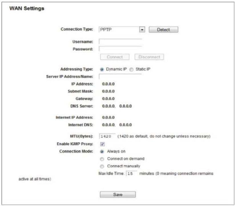
Figure 5-9. PPTP Settings.
- Username/Password—Enter the User Name and Password provided by your ISP. These fields are case-sensitive.
- Dynamic IP/ Static IP—Choose the addressing type given by your ISP, either Dynamic IP or Static IP, and enter the ISP's IP address or the domain name.
If you choose static IP and enter the domain name, you should also enter the DNS assigned by your ISP. Then click the Save button.
Click the Connect button to connect immediately. Click the Disconnect button to disconnect immediately.
- MTU (Bytes)—The default MTU size is "1420" bytes, which is usually fine. Do not change the default MTU Size unless required by your ISP.
- Enable IGMP Proxy—IGMP (Internet Group Management Protocol) is used to manage multicasting on TCP/IP networks. Some ISPs use IGMP to perform remote configuration for client devices, such as the modem router. The default value is enabled, if you are not sure, contact your ISP or just leave it.
- Connection Mode—Choose the Internet connection mode.
- Always on—In this mode, the Internet connection will be active all the time.
- Connect on Demand—You can configure the router to disconnect from your Internet connection after a specified period of inactivity (Max Idle Time). If your Internet connection has been terminated due to inactivity, Connect on Demand enables the router to automatically re-establish your connection as soon as you attempt to access the Internet again. If you wish to activate Connect on Demand, check the radio button. If you want your Internet connection to remain active at all times, enter "0" in the Max Idle Time field. Otherwise, enter the number of minutes you want to have elapsed before your Internet connection terminates.
- Connect Manually—You can configure the router to make it connect or disconnect manually. After a specified period of inactivity (Max Idle Time), the router will disconnect from your Internet connection, and you will not be able to re-establish your connection automatically as soon as you attempt to access the Internet again. To use this option, dick the radio button. If you want your Internet connection to remain active at all times, enter "0" in the Max Idle Time field. Otherwise, enter the number in minutes that you wish to have the Internet connecting last unless a new link is requested.
CAUTION: Sometimes the connection cannot be disconnected although you specify a time to Max Idle Time because some applications are visiting the Internet continually in the background.
Click the Save button to save your settings.
NOTE: If you don't know how to choose the appropriate connection type, click the Detect button to allow the router to automatically search your Internet connection for servers and protocols. The connection type will be reported when an active Internet service is successfully detected by the router. This report is for your reference only. To confirm the connection type your ISP provides, contact the ISP. The various types of Internet connections that the router can detect are as follows:
- PPPoE—Connections using PPPoE that require a user name and password.
- Dynamic IP—Connections that use dynamic IP address assignment.
- Static IP—Connections that use static IP address assignment.
The router cannot detect PPTP/L2TP/Big Pond connections with your ISP. If your ISP uses one of these protocols, then you must configure your connection manually.
5.4.2 LAN
Choose menu "Network → LAN", then you can configure the IP parameters of the LAN on the screen as below.
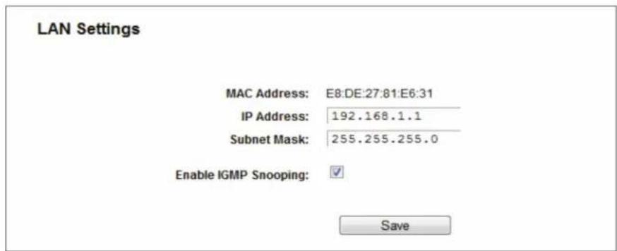
Figure 5-10. LAN Settings.
- MAC Address—The physical address of the router, as seen from the LAN. The value can't be changed.
- IP Address—Enter the IP address of your router or reset it in dotted-decimal notation (factory default: 192.168.1.1).
- Subnet Mask—An address code that determines the size of the network. Normally, networks use 255.255.255.0 as the subnet mask.
NOTES:
- If you change the IP Address of LAN, you must use the new IP Address to log in the router.
- If the new LAN IP Address you set is not in the same subnet, the IP Address pool of the DHCP server will change accordingly at the same timewhile the Virtual Server and DMZ Host will not take effect until they are re-configured.
5.4.3 MAC Clone
Choose menu "Network → MAC Clone", then you can configure the MAC address of the WAN on the screen below.
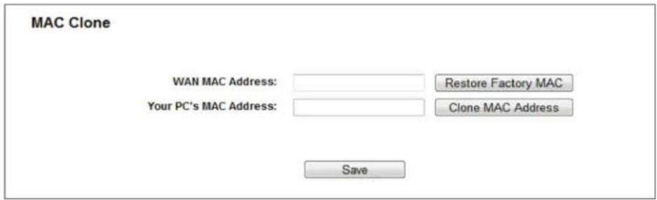
Figure 5-11. MAC Clone.
Some ISPs require that you register the MAC Address of your adapter. Changes are rarely needed here.
- WAN MAC Address—This field displays the current MAC address of the WAN port. If your ISP requires you to register the MAC address, enter the correct MAC address into this field in XX:XX:XX:XX:XX format (X is any hexadecimal digit).
- Your PC's MAC Address—This field displays the MAC address of the PC that is managing the router. If the MAC address is required, you can click the Clone MAC Address button and this MAC address will fill in the WAN MAC Address field.
Click Restore Factory MAC to restore the MAC address of WAN port to the factory default value.
Click the Save button to save your settings.
NOTE: Only the PC on your LAN can use the MAC Address Clone function.
5.5 Dual Band Selection
Choose the "Dual Band Selection" menu, then you can select the working frequency for your router. We recommend that your computers and devices running video and voice applications use the 5 GHz band, while your guest access and computers that are only browsing the web use the 2.4 GHz band.
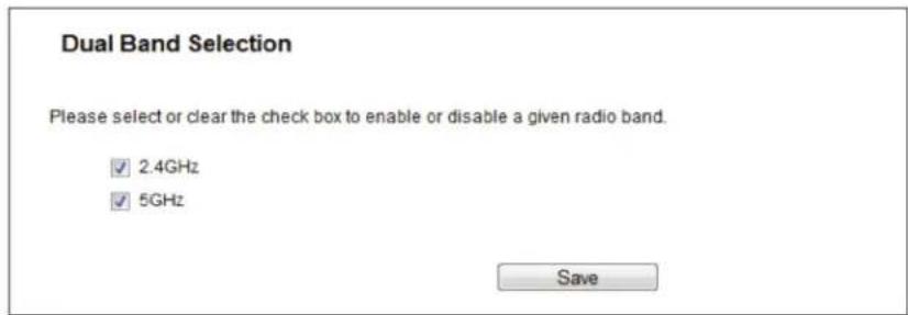
Figure 5-12. Dual Band Selection.
- 2.4 GHz (802.11b/g/n)—Click the box, then the router will only work at 2.4 GHz frequency. You can use the 2.4 GHz band to connect to many classic wireless devices like gaming consoles, laptops, DVRs, etc.
- 5 GHz (802.11a/n/ac)—Click the box, then the router will only work at 5 GHz frequency. This band is less crowded and is used for time-sensitive music, video streaming or gaming. Using this band can avoid interference with 2.4 GHz networks or noisy devices like cordless phones and microwave ovens.
5.6 Wireless 2.4 GHz
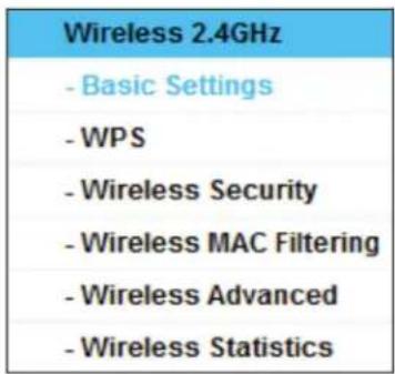
Figure 5-13. Wireless menu.
There are six submenus under the Wireless menu: Basic Settings, WPS, Wireless Security, Wireless MAC Filtering, Wireless Advanced, and Wireless Statistics. Click any of them, and you will be able to configure the corresponding functions.
5.6.1 Basic Settings
Choose menu "Wireless 2.4GHz Basic Settings." You can configure the basic settings for the wireless 2.4 GHz network on this page.
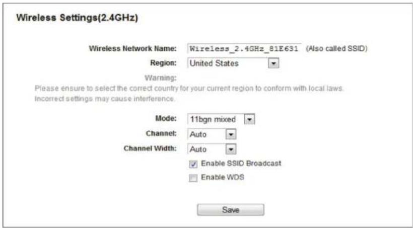
Figure 5-14. Wireless Settings—2.4 GHz.
- Wireless Network Name—Also called the SSID (Service Set Identification). Enter a value of up to 32 characters. The same name must be assigned to all wireless devices in your network. Considering your wireless network security, the default SSID is set to be Wireless_2.4GHz_XXXXXX. This value is case-sensitive.
For example, TEST is NOT the same as test.
- Region—Select your region from the drop-down list. This field specifies the region where the wireless function of the router can be used. It may be illegal to use the wireless function of the router in a region other than one of those specified in this field. If your country or region is not listed, please contact your local government agency for assistance.
When you select your local region from the drop-down list, click the Save button, then the Note Dialog appears. Click OK.
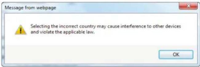
Figure 5-15. Message from webpage dialog box.
NOTE: Limited by local law regulations, version for North America does not have region selection option.
- Mode—Select the desired mode.
- 11bg mixed—Select if you are using both 802.11b and 802.11g wireless clients.
- 11bgn mixed—Select if you are using a mix of 802.11b, 11g, and 11n wireless clients. We strongly recommend that you set the Mode to 802.11bgn mixed, and all of 802.11b, 802.11g, and 802.11n wireless stations can connect to the router.
- Channel—This field determines which operating frequency will be used. The default channel is set to Auto, so the AP will choose the best channel automatically. You do not need to change the wireless channel unless you notice interference problems with another nearby access point.
- Channel Width—Select the channel width from the drop-down list. The default setting can automatically adjust the channel width for your clients.
NOTE: If 11bg mixed is selected in the Mode field, the Channel Width field will turn gray and the value will become 20M, which cannot be changed.
- Enable SSID Broadcast—When wireless clients survey the local area for wireless networks to associate with, they will detect the SSID broadcast by the router. If you select the Enable SSID Broadcast checkbox, the Wireless router will broadcast its name (SSID) on the air.
- Enable WDS—Check this box to enable WDS. With this function, the router can bridge two or more WLANs. If this checkbox is selected, you will have to set the following parameters as shown in Figure 4 14. Make sure the following settings are correct.
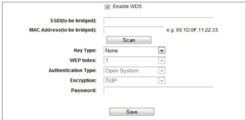
Figure 5-16. WDS Setting.
- SSID (to be bridged)—The SSID of the AP your router is going to connect to as a client. You can also use the search function to select the SSID to join.
-
MAC Address (to be bridged)—The BSSID of the AP your router is going to connect to as a client. You can also use the search function to select the BSSID to join.
-
Scan—Click this button, you can search the AP which runs in the current channel.
- Key type—This option should be chosen according to the AP's security configuration. We recommend setting the security type the same as your AP's security type.
- WEP Index—Choose this option if the key type is WEP(ASCII) or WEP(HEX). It indicates the index of the WEP key.
- Authentication Type—Choose this option if the key type is WEP(ASCII) or WEP(HEX). It indicates the authorization type of the Root AP.
- Encryption—When WPA is set as the Authentication Type, you can select either TKIP or AES as Encryption.
- Password—If the AP your router is going to connect needs a password, you need to fill the password in this blank.
5.6.2 WPS
Choose "Wireless 2.4GHz —> WPS", and the screen shown next will appear. This section will guide you to add a new wireless device to an existing network quickly by WPS (Wi-Fi Protected Setup) function.
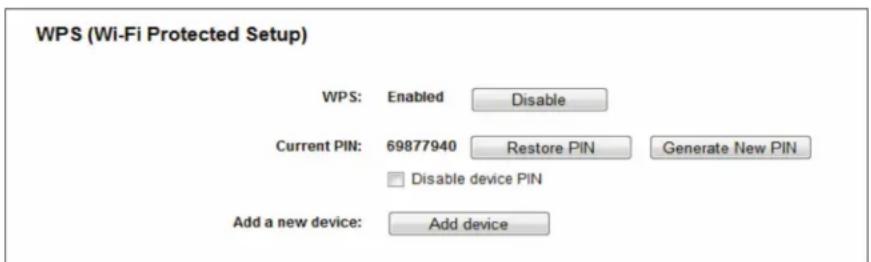
Figure 5-17. WPS.
- WPS—Enable or disable the WPS function here.
- Current PIN—The current value of the router's PIN is displayed here. The default PIN of the router can be found on the label.
- Restore PIN—Restore the PIN of the router to its default.
- Generate New PIN—Click this button, then you can get a new random value for the router's PIN. You can ensure the network security by generating a new PIN.
- Disable device PIN—If this box is checked, then wireless clients will not be able to connect to the wireless network with a PIN code.
- Add device—You can add a new device to the existing network manually by clicking this button.
If the wireless adapter supports Wi-Fi Protected Setup (WPS), you can establish a wireless connection between wireless adapter and router using either Push Button Configuration (PBC) method or PIN method.
NOTE: To build a successful connection by WPS, you should also do the corresponding configuration of the new device for WPS function meanwhile.
I. Use the Wi-Fi Protected Setup Button
Use this method if your client device has a WPS button.
Step 1: Press the WPS/Reset button on the back panel of the router, as shown in Figure 5-18. You can also keep the default WPS status as Enabled and click the Add device button in Figure 5-17. Then choose "Press the button of the new device in two minutes" and click Connect, shown in Figure 5-19.
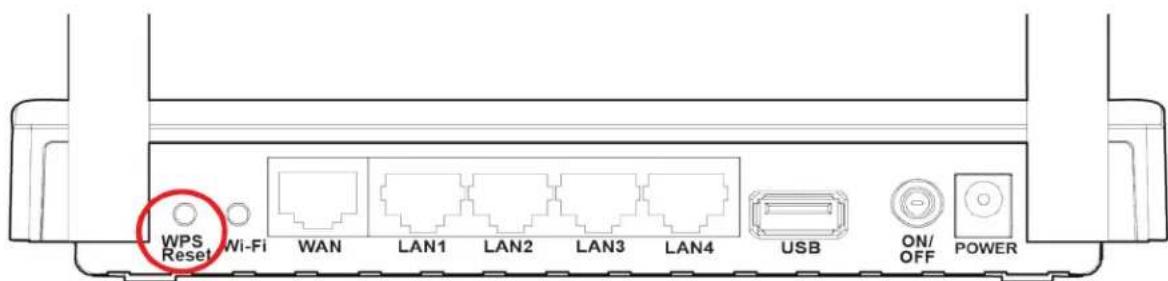
Figure 5-18. WPS/Reset button on the back of the router.

Figure 5-19. Add A New Device.
Step 2: Press and hold the WPS button of the client device.
Step 3: The Wi-Fi Protected Setup LED flashes for two minutes during the Wi-Fi Protected Setup process.
Step 4: When the WPS LED is on, the client device has successfully connected to the router.
II. Enter the client device's PIN on the router.
Use this method if your client device does not have the WPS button, but has a Wi-Fi Protected Setup PIN number.
Step 1: Keep the default WPS status as Enabled and click the Add device button in Figure 5 17, then Figure 5 20 will appear.
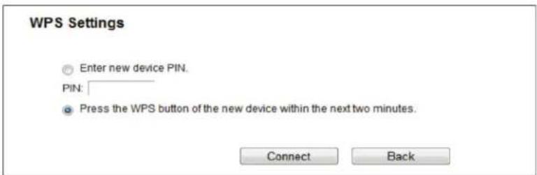
Figure 5-20. Add A New Device.
Step 2: Enter the PIN number from the client device in the field on the WPS screen above. Then click the Connect button.
Step 3: "Connect successfully" will appear on the screen, which means the client device has successfully connected to the router.
III. Enter the router's PIN on your client device.
Use this method if your client device asks for the router's PIN number.
Step 1: On the client device, enter the PIN number listed on the router's Wi-Fi Protected Setup screen. (It is also labeled on the bottom of the router.)
Step 2: The Wi-Fi Protected Setup LED flashes for two minutes during the Wi-Fi Protected Setup process.
Step 3: When the WPS LED is on, the client device has successfully connected to the router.
NOTES:
- The WPS LED on the router will light green for five minutes if the device has been successfully added to the network.
- The WPS function cannot be configured if the Wireless Function of the router is disabled. Please make sure the Wireless Function is enabled before configuring the WPS.
5.6.3 Wireless Security
Choose "Wireless 2.4GHz —> Wireless Security", then you can configure the security settings of your wireless network. There are five wireless security modes supported by the router: WPA-Personal, WPA2-Personal, WPA-Enterprise, WPA2-Enterprise, and WEP.
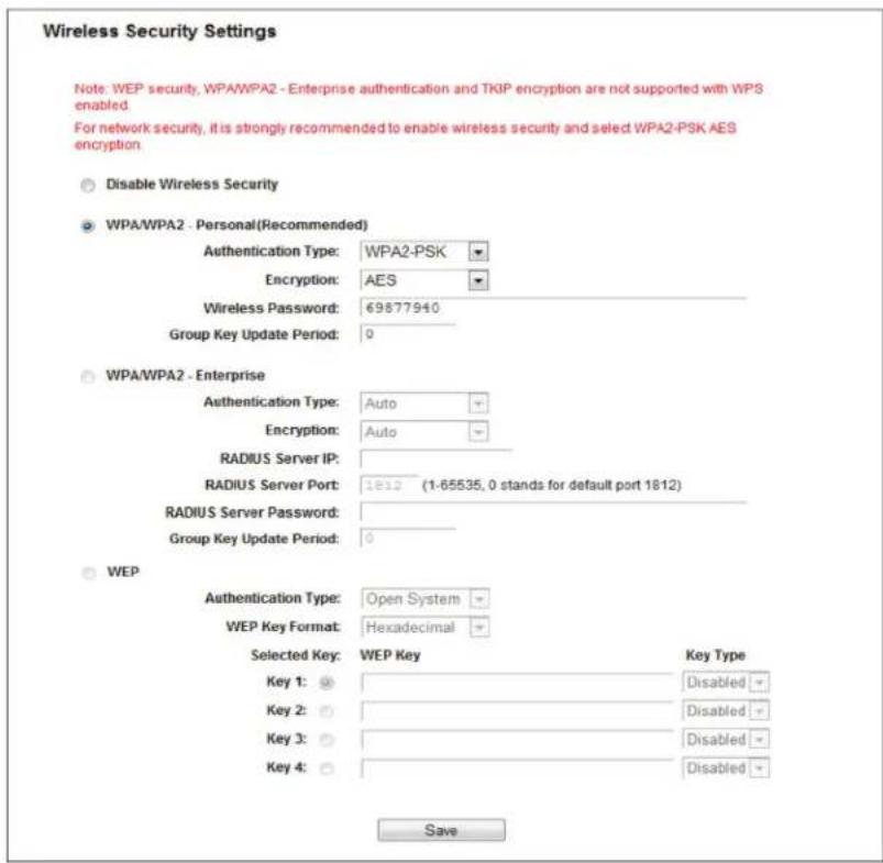
Figure 5-21. Wireless Security.
- Disable Wireless Security—If you do not want to use wireless security, check this radio button. But we strongly recommend that you choose one of the following modes to enable security.
- WPA/WPA2-Personal—This is the WPA/WPA2 authentication type based on a pre-shared passphrase. The router is configured by this security type by default.
- Authentication Type—Choose the version of the WPA-PSK security on the drop-down list. The default setting is Auto, which can select WPA-PSK (Pre-shared key of WPA) or WPA2-PSK (Pre-shared key of WPA) automatically based on the wireless station's capability and request.
- Encryption—When WPA-PSK or WPA is set as the Authentication Type, you can select either Automatic, or TKIP or AES as Encryption.
NOTE: If you check the WPA/WPA2-Personal radio button and choose TKIP encryption, you will find a notice in red as shown in Figure 5-22.

Figure 5-22. WPA/WPA2—Personal.
- Wireless Password—You can enter between 8 and 63 ASCII characters or 8 and 64 hexadecimal characters. The default password is the same as the default PIN code, which is labeled on the bottom of the router.
- Group Key Update Period - Specify the group key update interval in seconds. The value should be 30 or above. Enter 0 to disable the update.
- WPA/WPA2—Enterprise—This is based on Radius Server.
- Version—You can choose the version of the WPA security on the drop-down list. The default setting is Automatic, which can select WPA (Wi-Fi Protected Access) or WPA2 (WPA version 2) automatically based on the wireless station's capability and request.
- Encryption—You can select either Automatic, TKIP, or AES.
NOTE: If you check the WPA/WPA2-Enterprise radio button and choose TKIP encryption, you will find a notice in red as shown in Figure 5-23.
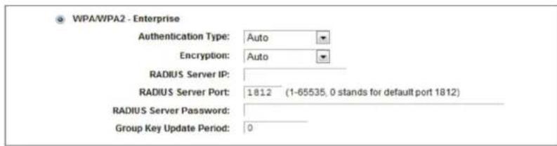
Figure 5-23. WPA/WPA2—Enterprise.
- Radius Server IP—Enter the IP address of the Radius server.
- Radius Server Port—Enter the port number of the Radius server.
- Radius Server Password—Enter the password for the Radius server.
- Group Key Update Period—Specify the group key update interval in seconds. The value should be 30 or above. Enter 0 to disable the update.
- WEP—This is based on the IEEE 802.11 standard. If you check this radio button, you will find a notice in red.
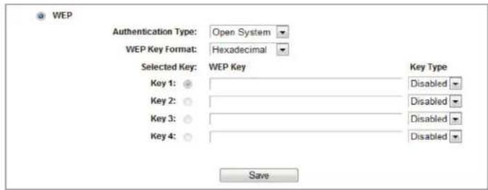
Figure 5-24. WEP.
- Authentication Type—you can choose the type for the WEP security on the drop-down list. The default setting is Auto, which can select Shared Key or Open System authentication type automatically based on the wireless station's capability and request.
- WEP Key Format—Hexadecimal and ASCII formats are provided here. Hexadecimal format stands for any combination of hexadecimal digits (0–9, a–f, A–F) in the specified length. ASCII format stands for any combination of keyboard characters in the specified length.
- WEP Key—Select which of the four keys will be used and enter the matching WEP key that you create. Make sure these values are identical on all wireless stations in your network.
- Key Type—You can select the WEP key length (64-bit, or 128-bit, or 152-bit.) for encryption. "Disabled" means this WEP key entry is invalid.
64-bit—You can enter 10 hexadecimal digits (any combination of 0–9, a–f, A–F, zero key is not promoted) or 5 ASCII characters.
128-bit—You can enter 26 hexadecimal digits (any combination of 0–9, a–f, A–F, zero key is not promoted) or 13 ASCII characters.
NOTE: If you do not set the key, the wireless security function is still disabled even if you have selected Shared Key as Authentication Type.
Be sure to click the Save button to save your settings on this page.
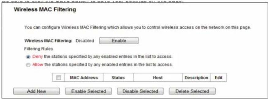
Figure 5-25. Wireless MAC filtering.
5.6.4 Wireless MAC Filtering
Choose "Wireless 2.4GHz —> Wireless MAC Filtering", then you can control the wireless access by configuring the Wireless MAC Filtering function.
To filter wireless users by MAC Address, click Enable. The default setting is Disabled.
- MAC Address—The wireless station's MAC address that you want to filter.
- Status—The status of this entry, either Enabled or Disabled.
- Host—The host network for the filtering rules.
• Description—A simple description of the wireless station.
To Add a Wireless MAC Address filtering entry, click the Add New button. The "Add or Modify Wireless MAC Address Filtering entry" page will appear.
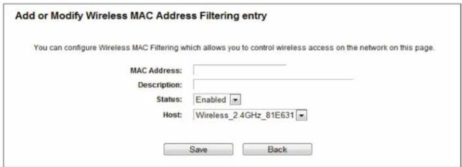
Figure 5-26. Add or Modify Wireless MAC Address Filtering entry.
To add or modify a MAC Address Filtering entry, follow these instructions:
- Enter the appropriate MAC Address into the MAC Address field. The format of the MAC Address is XX:XX:XX:XX:XX:XX (X is any hexadecimal digit). For example: 00:0A:EB:B0:00:0B.
- Give a simple description for the wireless station in the Description field. For example: Wireless station A.
- Select Enabled or Disabled for this entry on the Status drop-down list.
- Click the Save button to save this entry.
To edit or delete an existing entry:
-
Click Edit in the entry you want to modify. If you want to delete the entry, click Delete.
-
Modify the information.
-
Click the Save button.
Click the Enable Selected button to make selected entries enabled.
Click the Disable Selected button to make selected entries disabled.
Click the Delete Selected button to delete selected entries.
For example: To enable wireless station A with MAC address 00:0A:EB:B0:00:0B and wireless station B with MAC address 00:0A:EB:00:07:5F to access the router, but not allow all the other wireless stations to access the router, you can configure the Wireless MAC Address Filtering list by following these steps:
- Click the Enable button to enable this function.
- Select the radio button "Allow the entries specified by any enabled entries in the list to access" for Filtering Rules.
- Delete all or disable all entries if there are any entries already.
- Click the Add New button.
4a. Enter the MAC address 00:0A:EB:B0:00:0B /00:0A:EB:00:07:5F in the MAC Address field.
4b. Enter wireless station A/B in the Description field.
4c. Select Enabled in the Status drop-down list.
4d. Click the Save button.
The filtering rules that you configured should be similar to the following list:
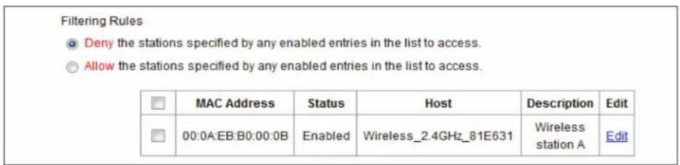
Figure 5-27. Filtering rules.
5.6.5 Wireless Advanced
Choose "Wireless 2.4GHz —> Wireless Advanced," then you can configure the advanced settings of your wireless network.
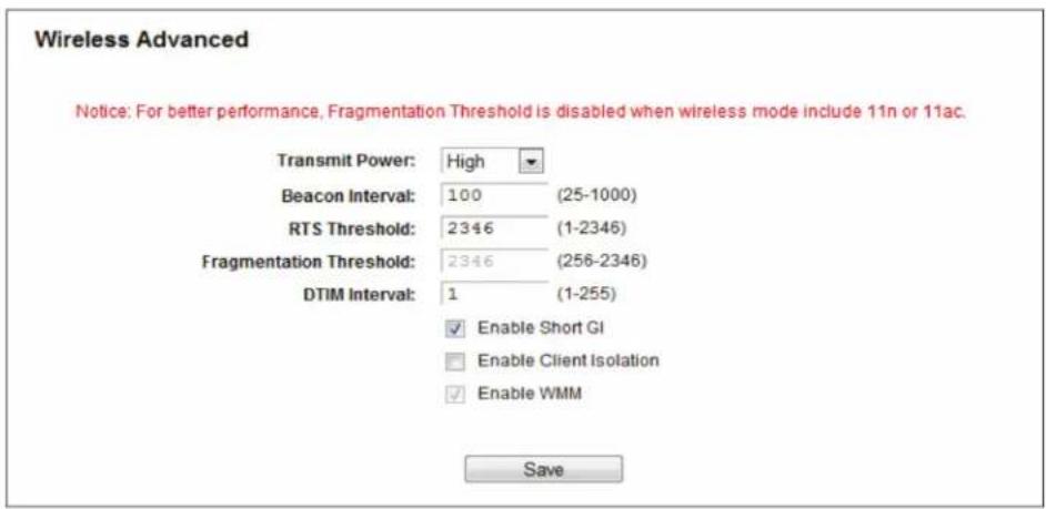
Figure 5-28. Wireless Advanced.
- Transmit Power—Here you can specify the transmit power of the router. You can select High, Middle, or Low. High is the default setting and is recommended.
- Beacon Interval—Enter a value between 20–1000 milliseconds for Beacon Interval here. The beacons are the packets sent by the router to synchronize a wireless network. Beacon Interval value determines the time interval of the beacons. The default value is 100.
- RTS Threshold —Here you can specify the RTS (Request to Send) Threshold. If the packet is larger than the specified RTS Threshold size, the router will send RTS frames to a particular receiving station and negotiate the sending of a data frame. The default value is 2346.
-
Fragmentation Threshold—This value is the maximum size that determines whether packets will be fragmented. Setting the Fragmentation Threshold too low may result in poor network performance because of excessive packets. 2346 is the default setting and is recommended.
-
DTIM Interval—This value determines the interval of the Delivery Traffic Indication Message (DTIM). A DTIM field is a countdown field informing clients of the next window for listening to broadcast and multicast messages. When the router has buffered broadcast or multicast messages for associated clients, it sends the next DTIM with a DTIM Interval value. You can specify the value between 1–15 Beacon Intervals. The default value is 1, which indicates the DTIM Interval is the same as the Beacon Interval.
- Enable WMM—WMM function can guarantee that the packets with high-priority messages are transmitted preferentially. It is strongly recommended.
- Enable Short GI—This function is recommended, because it will increase the data capacity by reducing the guard interval time.
- Enabled AP Isolation—This function can isolate wireless stations on your network from each other. Wireless devices will be able to communicate with the router but not with each other. To use this function, check this box. AP Isolation is disabled by default.
NOTE: If you are not familiar with the setting items in this page, it's strongly recommended to keep the provided default values; otherwise, it may result in lower wireless network performance.
5.6.6 Wireless Statistics
Choose "Wireless 2.4GHz —> Wireless Statistics," then you can see the MAC Address, Current Status, Received Packets, and Sent Packets for each connected wireless station.
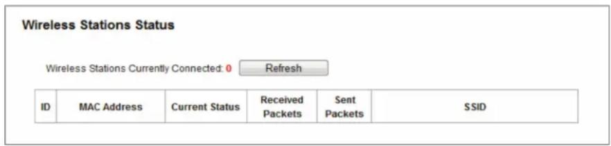
Figure 5-29. Wireless Statistics.
- MAC Address—The connected wireless station's MAC address
- Current Status—The running status of the connected wireless stations.
- Received Packets—Packets received by the station.
- Sent Packets—Packets sent by the station.
You cannot change any of the values on this page. To update this page and to show the current connected wireless stations, click on the Refresh button.
If the numbers of connected wireless stations go beyond one page, click the Next button to go to the next page and click the Previous button to return the previous page.
NOTE: This page will be refreshed automatically every 5 seconds.
5.7 Wireless 5 GHz
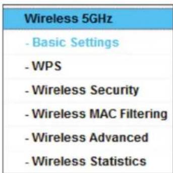
Figure 5-30. Wireless menu.
There are six submenus under the Wireless menu: Basic Settings, WPS, Wireless Security, Wireless MAC Filtering, Wireless Advanced, and Wireless Statistics. Click any of them, and you will be able to configure the corresponding functions.
5.7.1 Basic Settings
Choose "Wireless 5GHz —> Basic Settings," then you can configure the basic settings for the wireless network of 5 GHz on this page.
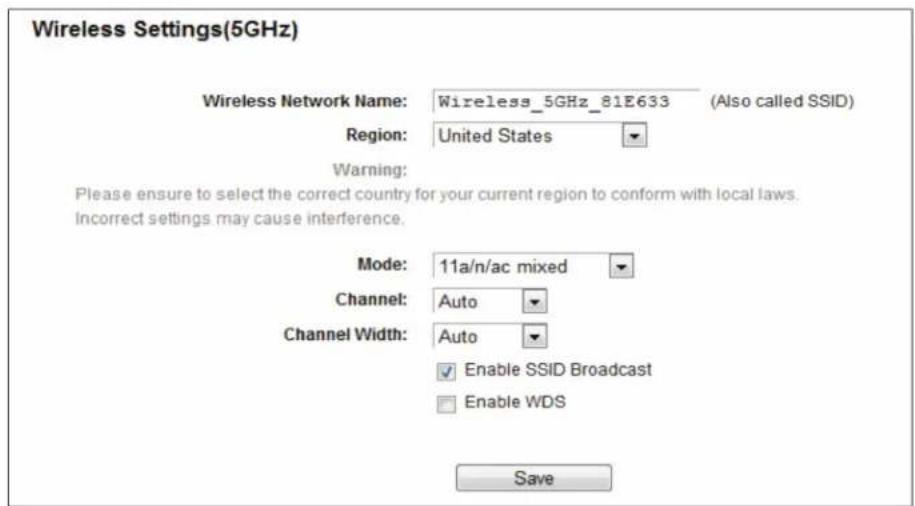
Figure 5-31. Wireless Settings—5 GHz.
- Wireless Network Name—Also called the SSID (Service Set Identification). Enter a value of up to 32 characters. The same name must be assigned to all wireless devices in your network. Considering your wireless network security, the default SSID is set to be Wireless_5GHz_XXXXXX. This value is case-sensitive. For example, TEST is NOT the same as test.
- Region—Select your region from the drop-down list. This field specifies the region where the wireless function of the router can be used. It may be illegal to use the wireless function of the router in a region other than one of those specified in this field. If your country or region is not listed, contact your local government agency for assistance.
When you select your local region from the drop-down list, click the Save button, then the Note Dialog appears. Click OK.
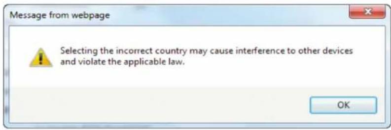
Figure 5-32. Message from webpage dialog box.
NOTE: Limited by local law regulations, the version for North America does not have region selection option.
- Mode—Select the desired mode.
- 11an mixed—Select if you are using both 802.11a and 802.11n wireless clients. If you set the Mode 11an mixed, all of 802.11a and 802.11n wireless stations can connect to the router.
- 11a/n/ac mixed—Select if you are using a mix of 802.11a, 802.11n, and 802.11ac wireless clients. We strongly recommend that you set the Mode 11a/n/ac mixed, so all 802.11a, 802.11n, and 802.11ac wireless stations can connect to the router.
- Channel—This field determines which operating frequency will be used. The default channel is set to Auto, so the router will choose the best channel automatically. You don't need to change the wireless channel unless you notice interference problems with another nearby access point.
- Enable SSID Broadcast—When wireless clients survey the local area for wireless networks to associate with, they will detect the SSID broadcast by the router. If you select the Enable SSID Broadcast checkbox, the Wireless router will broadcast its name (SSID) on the air.
- Enable WDS Bridging—Check this box to enable WDS. With this function, the router can bridge two or more WLANs. If this checkbox is selected, you will have to set the following parameters. Make sure these settings are correct.
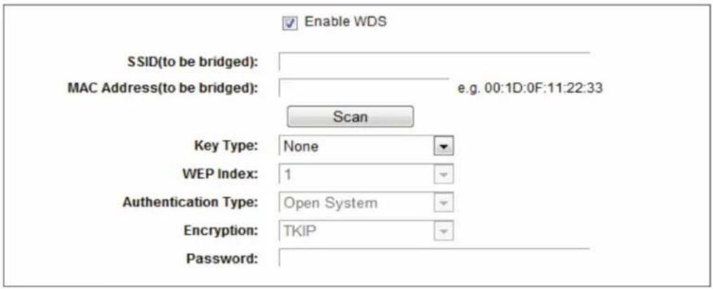
Figure 5-33. Enable WDS bridging.
- SSID (to be bridged)—The SSID of the AP that your router is going to connect to as a client. You can also use the search function to select the SSID to join.
- MAC Address (to be bridged)—The BSSID of the AP that your router is going to connect to as a client. You can also use the search function to select the BSSID to join.
-
Scan—Click this button, then you can search the AP that runs in the current channel.
-
Key type—Choose this option according to the AP's security configuration. We recommend that you set the security type the same as your AP's security type.
- WEP Index—Choose this option if the key type is WEP(ASCII) or WEP(HEX). It indicates the index of the WEP key.
- Authentication Type—Choose this option if the key type is WEP(ASCII) or WEP(HEX). It indicates the authorization type of the Root AP.
- Encryption—When WPA is set as the Authentication Type, you can select either TKIP or AES as Encryption.
- Password—If the AP your router is going to connect needs a password, type the password in this blank field.
5.7.2 WPS
Choose "Wireless 5GHz WPS," then you will see the screen as shown next. This section will explain how to add a new wireless device to an existing network quickly via WPS (Wi-Fi Protected Setup) function.
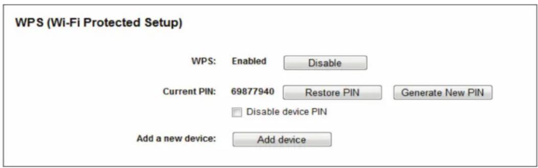
Figure 5-34. WPS.
- WPS—Enable or disable the WPS function here.
- Current PIN—The current value of the router's PIN is displayed here. The default PIN of the router is printed on the label.
- Restore PIN—Restore the PIN of the router to its default.
- Generate New PIN—Click this button, then you can get a new random value for the router's PIN. You can ensure network security by generating a new PIN.
- Add device—You can add a new device to the existing network manually by clicking this button.
If the wireless adapter supports Wi-Fi Protected Setup (WPS), you can establish a wireless connection between a wireless adapter and the router using either the Push Button Configuration (PBC) method or PIN method.
NOTE: To build a successful connection via WPS, you should also do configure the new device for WPS.
I. Use the Wi-Fi Protected Setup Button
Use this method if your client device has a Wi-Fi Protected Setup button.
Step 1: Press the WPS/Reset button on the back panel of the router. You can also keep the default WPS status as Enabled and click the Add device button. Then choose "Press the button of the new device in two minutes" and click Connect.
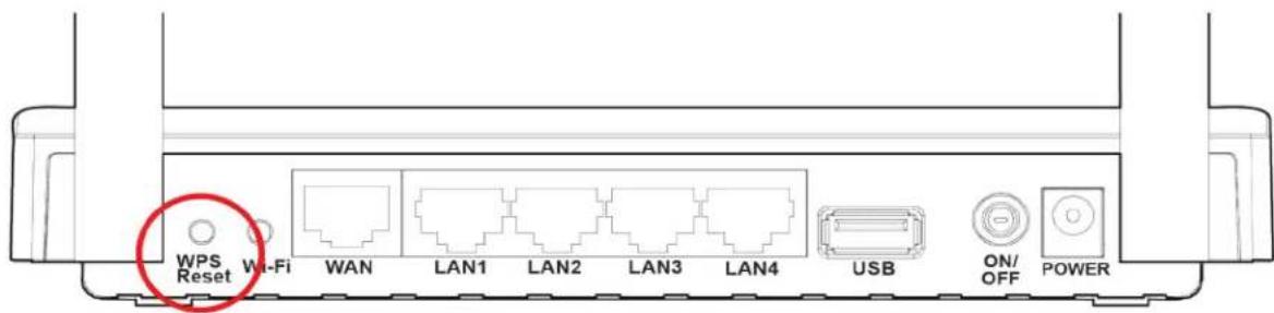
Figure 5-35. Back panel of the router.
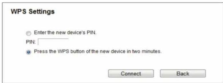
Figure 5-36. Add A New Device.
Step 2: Press and hold the WPS button of the client device.
Step 3: The Wi-Fi Protected Setup LED flashes for two minutes during the Wi-Fi Protected Setup process.
Step 4: When the WPS LED is on, the client device has successfully connected to the router.
II. Enter the client device's PIN on the router.
Use this method if your client device does not have the WPS button, but has a Wi-Fi Protected Setup PIN number.
Step 1: Keep the default WPS status as Enabled and click the Add device button in Figure 4 30, then Figure 4 33 will appear.
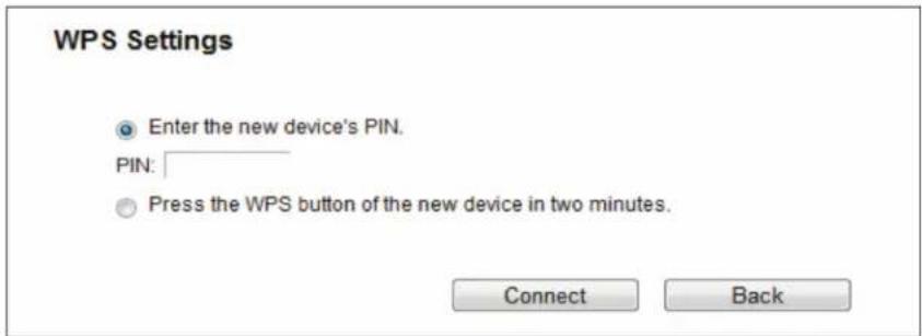
Figure 5-37. Add A New Device.
Step 2: Enter the PIN number from the client device in the field on the above WPS screen. Then click the Connect button.
Step 3: "Connect successfully" will appear on the screen, which means the client device has successfully connected to the router. III. Enter the router's PIN on your client device.
Use this method if your client device asks for the router's PIN number.
Step 1: On the client device, enter the PIN number listed on the router's Wi-Fi Protected Setup screen. (It is also labeled on the bottom of the router.)
Step 2: The Wi-Fi Protected Setup LED flashes for two minutes during the Wi-Fi Protected Setup process.
Step 3: When the WPS LED is on, the client device has successfully connected to the router.
NOTES:
- The WPS LED on the router will light green for five minutes if the device has been successfully added to the network.
- The WPS function cannot be configured if the Wireless Function of the router is disabled. Make sure the Wireless Function is enabled before configuring the WPS.
5.7.3 Wireless Security
Choose "Wireless 5GHz —> Wireless Security," then you can configure the security settings of your wireless network.
There are five wireless security modes supported by the router: WPA-Personal, WPA2-Personal, WPA-Enterprise, WPA2-Enterprise, and WEP.
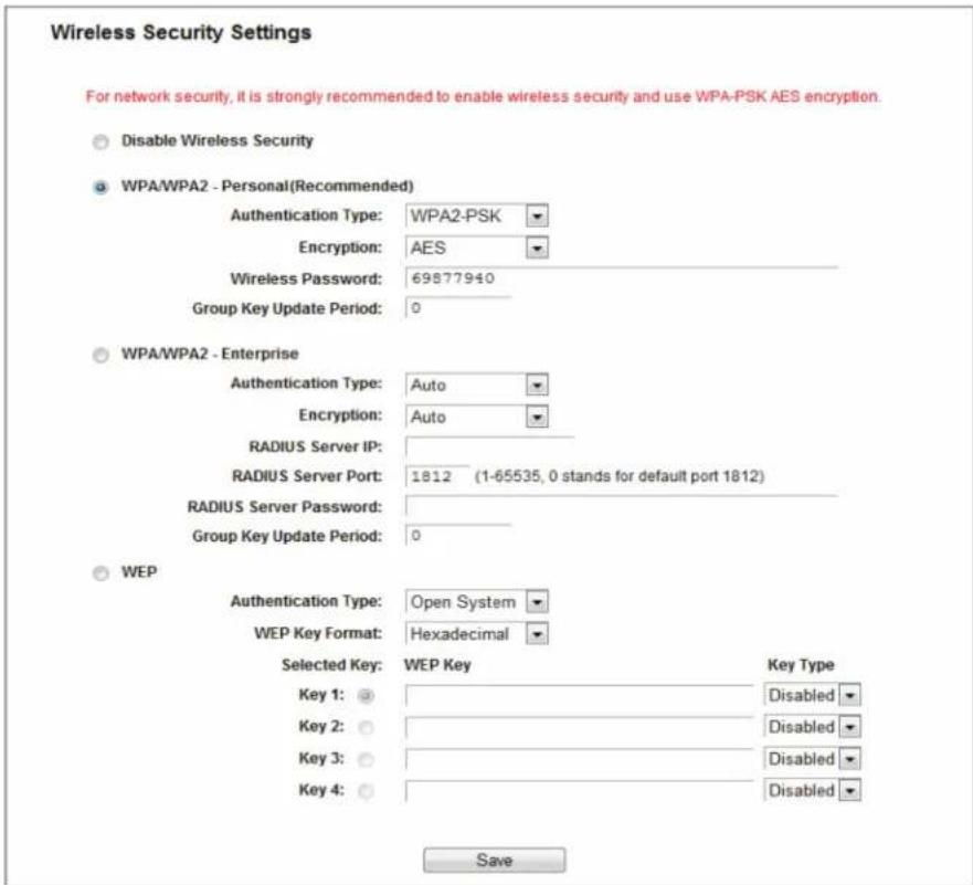
Figure 5-38. Wireless Security.
- Disable Security—If you do not want to use wireless security, check this radio button. We strongly recommend that you choose one of the following modes to enable security.
- WPA/WPA2-Personal—This is the WPA/WPA2 authentication type based on pre-shared passphrase. The router is configured by this security type by default.
- Authentication Type—You can choose the version of the WPA-PSK security on the drop-down list. The default setting is Automatic, which will select WPA-PSK (Pre-shared key of WPA) or WPA2-PSK (Pre-shared key of WPA) automatically based on the wireless station's capability and request.
- Encryption—When WPA-PSK or WPA is set as the Authentication Type, you can select either Automatic, or TKIP or AES as Encryption.
NOTE: If you check the WPA/WPA2-Personal radio button and choose TKIP encryption, you will find a notice in red.

Figure 5-39. WPA/WPA2—Personal.
- Wireless Password—You can enter between 8 and 63 ASCII characters or 8 and 64 hexadecimal characters. The default password is the same with the default PIN code, which is labeled on the bottom of the router.
- Group Key Update Period—Specify the group key update interval in seconds. The value should be 30 or above. Enter 0 to disable the update.
- WPA /WPA2—Enterprise—This is based on the Radius Server.
- Authentication Type—You can choose the version of the WPA security on the drop-down list. The default setting is Automatic, which selects WPA (Wi-Fi Protected Access) or WPA2 (WPA version 2) automatically based on the wireless station's capability and request.
- Encryption—You can select either Automatic, TKIP, or AES.
NOTE: If you check the WPA/WPA2-Enterprise radio button and choose TKIP encryption, you will find a notice in red.
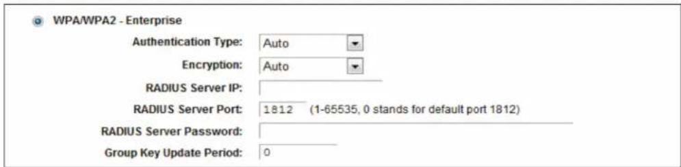
Figure 5-40. WPA/WPA2—Enterprise.
- Radius Server IP—Enter the IP address of the Radius server.
- Radius Server Port—Enter the port number of the Radius server.
- Radius Server Password—Enter the password for the Radius server.
- Group Key Update Period—Specify the group key update interval in seconds. The value should be 30 or above. Enter 0 to disable the update.
- WEP—This is based on the IEEE 802.11 standard. If you check this radio button, you will see a notice in red.
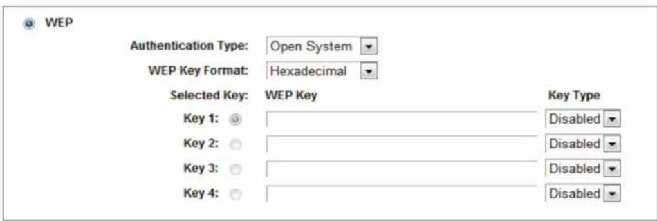
Figure 5-41. WEP.
- Authentication Type—You can choose the type for the WEP security on the drop-down list. The default setting is Automatic, which selects Shared Key or Open System authentication type automatically based on the wireless station's capability and request.
- WEP Key Format—Hexadecimal and ASCII formats are provided here. Hexadecimal format stands for any combination of hexadecimal digits (0–9, a–f, A–F) in the specified length. ASCII format stands for any combination of keyboard characters in the specified length.
- WEP Key—Select which of the four keys will be used and enter the matching WEP key that you create. Make sure these values are identical on all wireless stations in your network.
- Key Type—You can select the WEP key length (64-bit, or 128-bit, or 152-bit.) for encryption. "Disabled" means this WEP key entry is invalid.
64-bit—You can enter 10 hexadecimal digits (any combination of 0–9, a–f, A–F, zero key is not promoted) or 5 ASCII characters.
128-bit—You can enter 26 hexadecimal digits (any combination of 0–9, a–f, A–F, zero key is not promoted) or 13 ASCII characters.
NOTE: If you do not set the key, the wireless security function is still disabled even if you have selected Shared Key as Authentication Type.
Click the Save button to save your settings on this page.
5.7.4 Wireless MAC Filtering
Choose "Wireless—> MAC Filtering," then you can control the wireless access by configuring the Wireless MAC Filtering function.
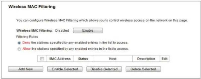
Figure 5-42. Wireless MAC Filtering.
To filter wireless users by MAC Address, click Enable. The default setting is Disabled.
- MAC Address—The wireless station's MAC address that you want to filter.
- Status—The status of this entry, either Enabled or Disabled.
- Host—The host network for the filtering rules.
• Description—A simple description of the wireless station.
To Add a Wireless MAC Address filtering entry, click the Add New button. The "Add or Modify Wireless MAC Address Filtering entry" page will appear.
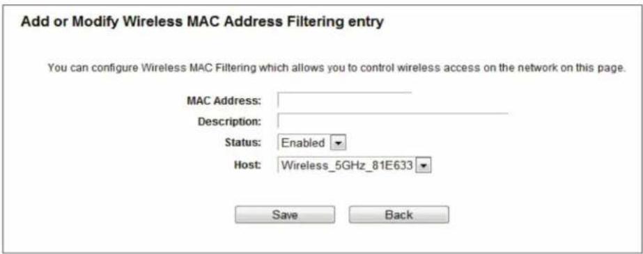
Figure 5-43. Add or Modify Wireless MAC Address Filtering entry.
To add or modify a MAC Address Filtering entry, follow these instructions:
- Enter the appropriate MAC Address into the MAC Address field. The format of the MAC Address is XX:XX:XX:XX:XX:XX (X is any hexadecimal digit). For example: 00:0A:EB:B0:00:0B.
- Give a simple description for the wireless station in the Description field. For example: Wireless station A.
- Select Enabled or Disabled for this entry on the Status drop-down list.
- Select the Host for the entry.
- Click the Save button to save this entry.
To modify or delete an existing entry:
- Click Modify in the entry you want to modify. If you want to delete the entry, click Delete.
- Modify the information.
- Click the Save button.
Click the Enable Selected button to make the selected entries enabled.
Click the Disable Selected button to make the selected entries disabled.
Click the Delete Selected button to delete the selected entries.
Click the Back button to return to the previous page.
For example: To enable wireless station A with MAC address 00:0A:EB:B0:00:0B and wireless station B with MAC address 00:0A:EB:00:07:5F to access the router, with all the other wireless stations unable to access the router, you can configure the Wireless MAC Address Filtering list by following these steps:
- Click the Enable button to enable this function.
-
Select the radio button "Allow the entries specified by any enabled entries in the list to access" for Filtering Rules.
-
Delete all or disable all entries if there are any entries already.
- Click the Add New button.
- Enter the MAC address 00:0A:EB:B0:00:0B /00:0A:EB:00:07:5F in the MAC Address field.
- Enter wireless station A/B in the Description field.
- Select Enabled in the Status drop-down list.
- Click the Save button.
- Click the Back button.
The filtering rules that you configured should be similar to the following:
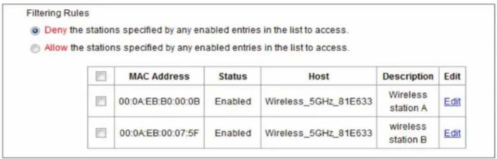
Figure 5-44. Filtering rules screen.
5.7.5 Wireless Advanced
Choose "Wireless → Wireless Advanced," then you can configure the advanced settings of your wireless network.
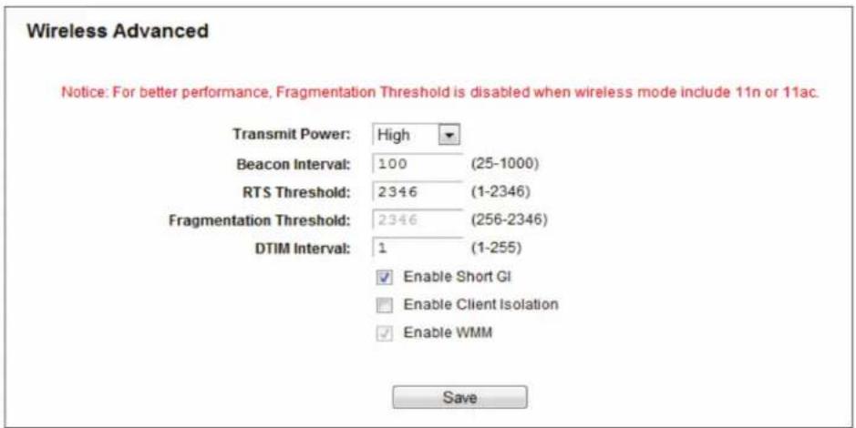
Figure 5-45. Wireless Advanced.
- Transmit Power—Here you can specify the transmit power of router. You can select High, Middle, or Low. High is the default setting and is recommended.
- Beacon Interval—Enter a value between 20–1000 milliseconds for Beacon Interval here. The beacons are the packets sent by the router to synchronize a wireless network. Beacon Interval value determines the time interval of the beacons. The default value is 100.
- RTS Threshold—Here you can specify the RTS (Request to Send) Threshold. If the packet is larger than the specified RTS Threshold size, the router will send RTS frames to a particular receiving station and negotiate the sending of a data frame. The default value is 2346.
- Fragmentation Threshold—This value is the maximum size that determines whether packets will be fragmented. Setting the Fragmentation Threshold too low may result in poor network performance because of excessive packets. 2346 is the default setting and is recommended.
- DTIM Interval—This value determines the interval of the Delivery Traffic Indication Message (DTIM). A DTIM field is a countdown field informing clients of the next window for listening to broadcast and multicast messages. When the router has buffered broadcast or multicast messages for associated clients, it sends the next DTIM with a DTIM Interval value. You can specify the value between 1–15 Beacon Intervals. The default value is 1, which indicates the DTIM Interval is the same as Beacon Interval.
- Enable WMM—The WMM function guarantees that packets with high-priority messages are transmitted preferentially. It is strongly recommended.
- Enable Short GI—We recommend this function because it will increase the data capacity by reducing the guard interval time.
- Enabled AP Isolation—This function isolates wireless stations on your network from each other. Wireless devices will be able to communicate with the router but not with each other. To use this function, check this box. AP Isolation is disabled by default.
NOTE: If you are not familiar with the setting items in this page, we strongly recommend that you keep the provided default values; otherwise, it may result in lower wireless network performance.
5.7.6 Wireless Statistics
Choose menu "Wireless —> Wireless Statistics," then you can see the MAC Address, Current Status, Received Packets, and Sent Packets for each connected wireless station.
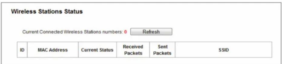
Figure 5-46. Wireless Statistics.
- MAC Address—The connected wireless station's MAC address.
- Current Status—The connected wireless station's running status.
- Received Packets—Packets received by the station.
- Sent Packets—Packets sent by the station.
You cannot change any of the values on this page. To update this page and to show the current connected wireless stations, click on the Refresh button.
If the numbers of connected wireless stations go beyond one page, click the Next button to go to the next page and click the Previous button to return the previous page.
NOTE: This page will be refreshed automatically every 5 seconds.
5.8 Guest Network
Choose "Guest Network," then you can configure the Guest Network Wireless Settings on the page.
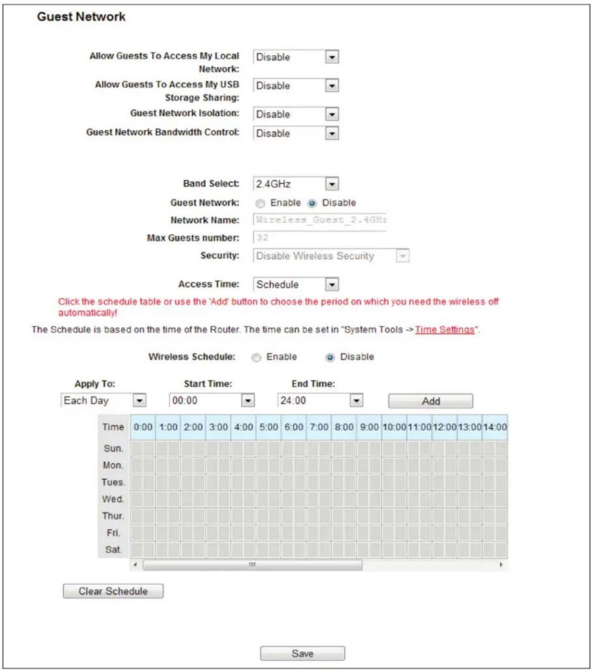
Figure 5-47. Guest Network Wireless Settings.
- Allow Guest To Access My Local Network—If enabled, guests can communicate with hosts.
- Allow Guest To Access My USB Storage Sharing—If enabled, guests can access to USB storage sharing servers.
- Guest Network Isolation—If enabled, guests are isolated from each other.
- Guest Network Bandwidth Control—If enabled, the Guest Network Bandwidth Control rules will take effect.
- Band Select/Guest Network—Select the wireless network band (2.4 G / 5 G) and enable or disable its Guest Network function.
- Network Name—Enter a value of up to 32 characters. The same Name (SSID) must be assigned to all wireless devices in your Guest Network.
- Max Guest number—The maximum number of guests at the same time.
• Security—You can configure the security of the Guest Network here. - Access Time—During this time the wireless stations can access the AP.
NOTE: The range of bandwidth for Guest Network is calculated according to the "Bandwidth Control->Control Settings" page.
5.9 DHCP
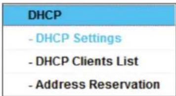
Figure 5-48. The DHCP menu.
There are three submenus under the DHCP menu: DHCP Settings, DHCP Clients List, and Address Reservation. Click any of them, and you will be able to configure the corresponding functions.
5.9.1 DHCP Settings
Choose "DHCP —> DHCP Settings," then you can configure the DHCP Server on the page. The router is set up by default as a DHCP (Dynamic Host Configuration Protocol) server, which provides the TCP/IP configuration for all the PC(s) that are connected to the router on the LAN.
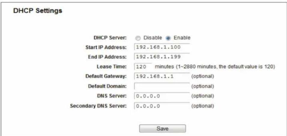
Figure 5-49. DHCP Settings.
- DHCP Server—Enable or Disable the DHCP server. If you disable the Server, you must have another DHCP server within your network; otherwise, you must configure the computer manually.
- Start IP Address—Specify an IP address for the DHCP Server to start with when assigning IP addresses. 192.168.1.100 is the default start address.
- End IP Address—Specify an IP address for the DHCP Server to end with when assigning IP addresses. 192.168.1.199 is the default end address.
- Lease Time—The Lease Time is the amount of time a network user will be allowed connection to the router with their current dynamic IP Address. Enter the amount of time in minutes and the user will be “leased” this dynamic IP Address. After the time is up, the user will be automatically assigned a new dynamic IP address. The range of the time is 1–2880 minutes. The default value is 120 minutes.
- Default Gateway—(Optional.) We suggest that you input the IP address of the LAN port of the router. The default value is 192.168.1.1.
- Default Domain—(Optional.) Input the domain name of your network.
- Primary DNS—(Optional.) Input the DNS IP address provided by your ISP or consult your ISP.
- Secondary DNS—(Optional.) Input the IP address of another DNS server if your ISP provides two DNS servers.
NOTE: To use the DHCP server function of the router, you must configure all computers on the LAN to "Obtain an IP Address automatically."
5.9.2 DHCP Clients List
Choose "DHCP —> DHCP Clients List," then you can view the information about the clients attached to the router in the screen.
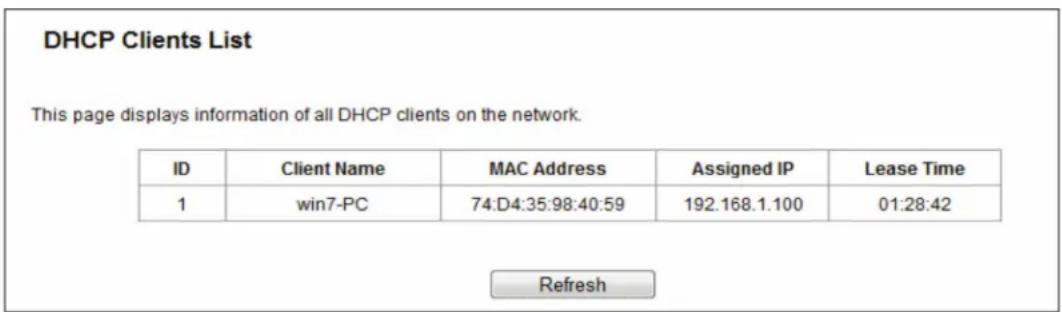
Figure 5-50. DHCP Clients List.
- Client Name—The name of the DHCP client.
• MAC Address—The MAC address of the DHCP client. - Assigned IP—The IP address that the router has allocated to the DHCP client.
- Lease Time—The time the DHCP client lease is active. After the dynamic IP address has expired, a new dynamic IP address will be automatically assigned to the user.
You cannot change any of the values on this page. To update this page and to show the current attached devices, click the Refresh button.
5.9.3 Address Reservation
Choose "DHCP —> Address Reservation," then you can view and add a reserved address for clients via the next screen. When you specify a reserved IP address for a PC on the LAN, that PC will always receive the same IP address each time it accesses the DHCP server. Assign reserved IP addresses to servers that require permanent IP settings.
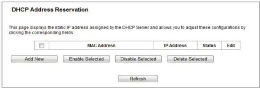
Figure 5-51. Address Reservation.
- MAC Address—The MAC address of the PC for which you want to reserve an IP address.
- IP Address—The IP address reserved for the PC by the router.
- Status—The status of this entry, either Enabled or Disabled.
To reserve an IP address:
- Click the Add New button. The DHCP Address Reservation screen will appear.
- Enter the MAC address (in XX:XX:XX:XX:XX:XX format) and the IP address (in dotted-decimal notation) of the computer for which you want to reserve an IP address.
- Click the Save button.
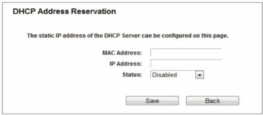
Figure 5-52. Add or Modify an Address Reservation Entry.
To modify or delete an existing entry:
- Click Edit in the entry you want to modify. If you want to delete the entry, click Delete.
- Modify the information.
- Click the Save button.
Click the Enable/Disable Selected button to enable/disable selected entries.
Click the Delete Selected button to delete selected entries.
5.10 USB Settings
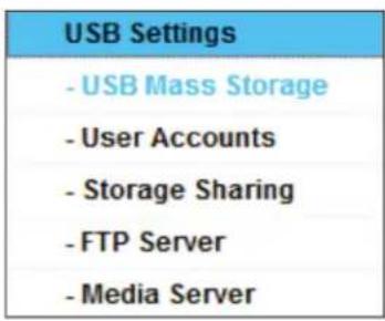
Figure 5-53. The USB Settings menu.
There are six submenus under the USB Settings menu: USB Mass Storage, User Accounts, Storage Sharing, FTP Server, and Media Server. Click any of them, and you will be able to configure the corresponding functions.
5.10.1 USB Mass Storage
The USB Mass Storage page provides basic information about the USB mass storage device. Click the Refresh button to update this page.
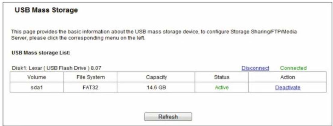
Figure 5-54. USB Mass Storage screen.
5.10.2 User Accounts
You can specify the user name and password for Storage Sharing and FTP Server users on this page. Storage Sharing users can use Internet Explorer to access files on the USB drive. FTP Server users can log into the FTP Server via FTP Client.
The default user account is admin. It has read/write access to Storage Sharing and can access FTP Server.
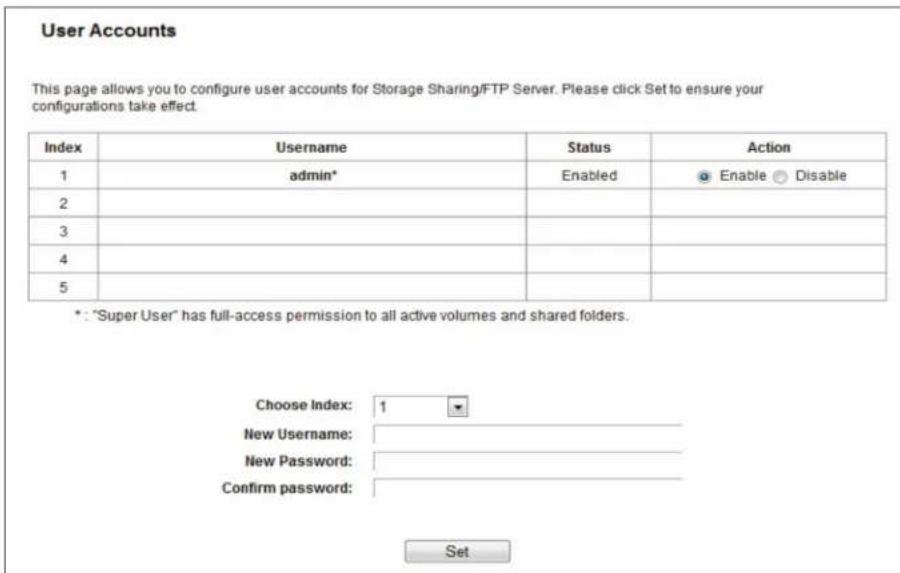
Figure 5-55. User Account Management screen.
Only an Administrator can use a Web browser to transfer the files from a PC to the writable shared volume on the USB drive.
To add a new user account, follow the steps below:
- Choose the Index from the drop-down list.
- Self-define a User Name.
- Enter the password in the Password field.
- Re-enter the password in the Confirm Password field.
-
Click Set to make your settings take effect.
-
New Username—Type the user name that you want to give access to the USB drive. The user name must be composed of alphanumeric symbols not exceeding 15 characters in length.
- New Password—Enter the password in the Password field. The password must be composed of alphanumeric symbols not exceeding 15 characters in length. For security purposes, the password for each user account is not displayed.
- Confirm Password - Re-enter the password here.
NOTES:
- Restart the service for the new settings to take effect.
- If you cannot use the new user name and password to access the shares, press Windows logo + R to open the Run dialog box and type net use \192.168.1.1 /delete /yes and press Enter. (192.168.1.1 is your router's LAN IP address. If the LAN IP of the modem connected with your router is 192.168.1.x, the default LAN IP of the router will automatically switch from 192.168.1.1 to 192.168.0.1 to avoid IP conflict; in this case, try net use \192.168.0.1 /delete / yes.)
5.10.3 Storage Sharing
Choose "USB Settings Storage Sharing," then you can configure a USB disk drive attached to the router and view volume and share properties such as share name, directory, user access, and status on this page as shown below.
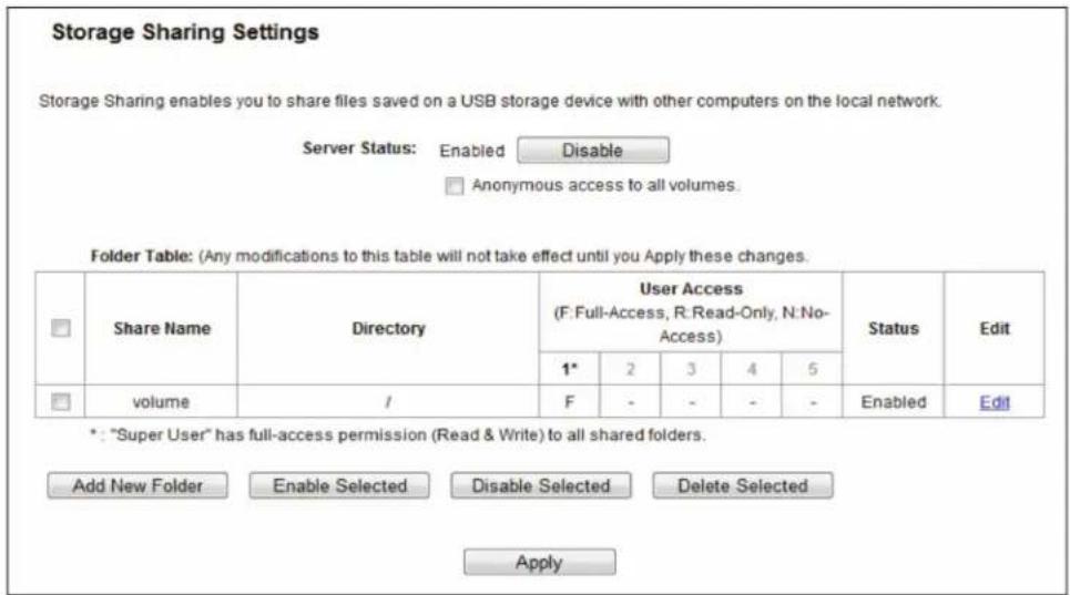
Figure 5-56. Storage Sharing.
- Server Status—Indicates the Storage Sharing server's current status. You can click the Enable button to start the Storage Sharing service and click the Disable button to stop it.
- Anonymous access to all volumes—Check this box to allow users to access all volumes without username or password.
- Shared Name—The volume name of the USB drive the users have access to.
- Directory—The directory of the shared folder.
- User Access—Indicates user access of the shared folder. F stands for fully access, R stands for read-only, and N stands for no-access.
- Status—Indicates the shared or non-shared status of the volume.
- Edit—Click Edit to edit the entry.
To add a new folder, follow the instructions below.
- Click Add New Folder in the next screen.
Folder Browse
This page allows to set shared folders along with authorization access for Storage Sharing services. These configurations will not take effect when Anonymous access has been enabled.
Share Name:
Directory:
Browse
User Access Control Table:
| Index | Username | Authorization Access |
| 1* | admin | Full-AccessRead-OnlyNo-Access |
| 2 | guest | Full-AccessRead-OnlyNo-Access |
| 3 | ||
| 4 | ||
| 5 |
* : "Super User". It has full-access permission (Read & Write) to all active volume(s) and share folder(s).
Apply
Figure 5-57. Add or Modify Share Folder screen.
- Enter the display name of the shared folder in Shared Name field.
- Click the Browse button to select the folder that you want to share.
- Click the Apply button to save the settings.
NOTES:
- The max shared folders number is 10. If you want to share a new folder when the number has reached 10, you can delete an existing shared folder and then add a new one.
- If you want to change the FTP settings, you need to restart FTP Server to make the changes take effect.
Click the Enable Selected button to make the selected entries enabled.
Click the Disable Selected button to make the selected entries disabled.
Click the Delete Selected button to delete the selected entries.
Click the Apply button to make the settings take effect.
5.10.4 FTP Server
Choose "USB Settings FTP Server," then you can create an FTP server that can be accessed from the Internet or your local network.
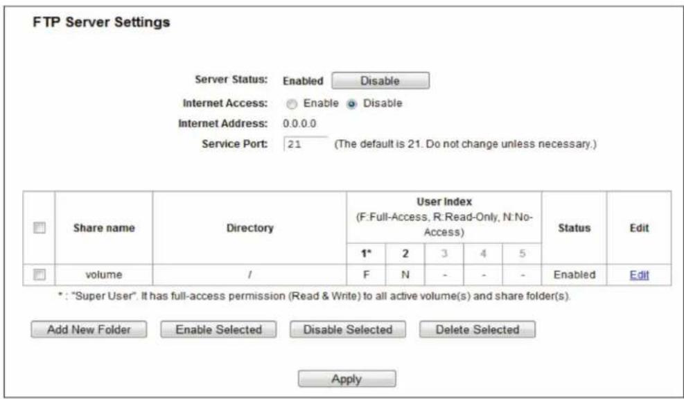
Figure 5-58. FTP Server Configuration.
- Server Status—Indicates the FTP Server's current status.
- Internet Access—Select enable to allow access of the FTP server from the Internet. Otherwise, select disable to only allow local network access.
- Internet Address—The WAN IP address of this router.
• Service Port—Enter the FTP Port number to use. The default is 21.
To set up your FTP Server, please follow the instructions below:
- Plug an external USB hard disk drive or USB flash drive into this router.
- Click the Enable/Disable radio box to enable/disable Internet access to the FTP from the WAN port.
- Specify a port for the FTP server to use. (The default port number is 21.)
- The Internet Address displays the WAN IP address of this router, so that other users can access the FTP via this address.
- If the WAN type is PPPoE/PPTP/L2TP, two connections will be available. Users can access FTP server via two connections. Users in a private LAN can access ftp server via a Public Address while Internet users can access the ftp server via an Internet Address.
- Click the Apply button to start the ftp server.
To add a new folder, follow the instructions below.
- Click Add New Folder in Figure 5-59.
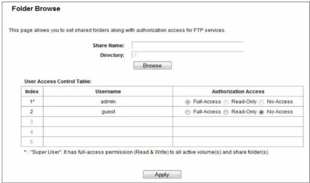
Figure 5-59. Add or Modify Share Folder.
- Enter display name of the share folder in Shared Name field.
- Click the Browse button to select the folder that you want to share.
- Click the Apply button to save the settings.
NOTES:
- The max shared folders number is 10. If you want to share a new folder when the number has reached 10, you can delete an existing shared folder and then add a new one.
- If you want to change the FTP settings, you need to restart FTP Server to make the changes take effect.
5.10.5 Media Server
Choose "USB Settings Media Server," then you can create a media server that allows you to share stored content with other computers and devices on your home network and on the Internet.
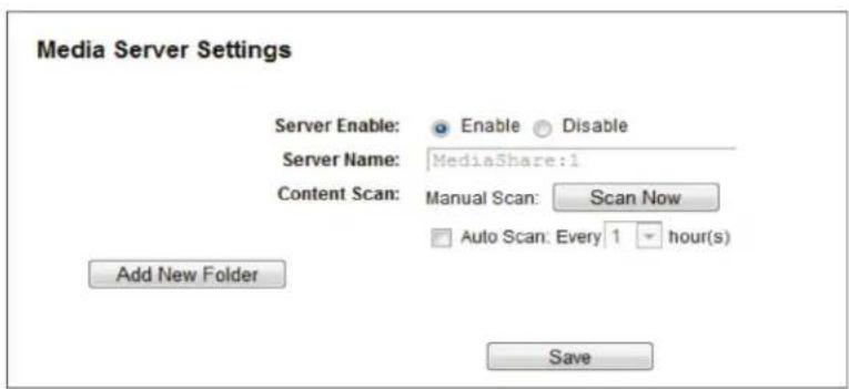
Figure 5-60. Media Server Setting.
- Server Enable—Indicates the Media Server's current status, started or stopped. You can click the Enable button to enable the Media Server and click the Disable button to disable it.
- Server Name—The name of this Media Server.
- Share Name—The display name of this folder.
- Folder Name—The real full path of the specified folder.
- Delete—You can delete the share folder by clicking Delete.
To set up your media server, follow the instructions below:
- Plug an external USB hard disk drive or USB flash drive into this router, and then click the Enable button to start the media server. The screen will appear as shown in Figure 5-61.
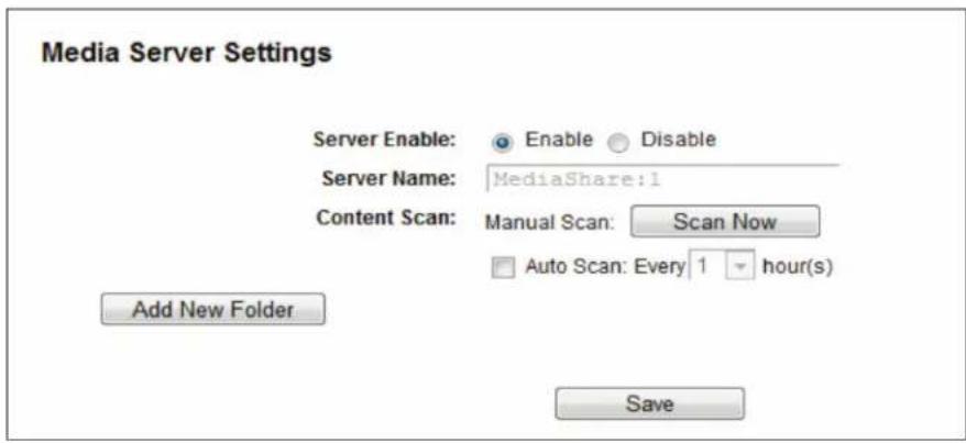
Figure 5-61. Add New Folder.
- Click the Add New Folder button to specify a folder as the search path of media server. The screen will then appear as shown in Figure 5-62.
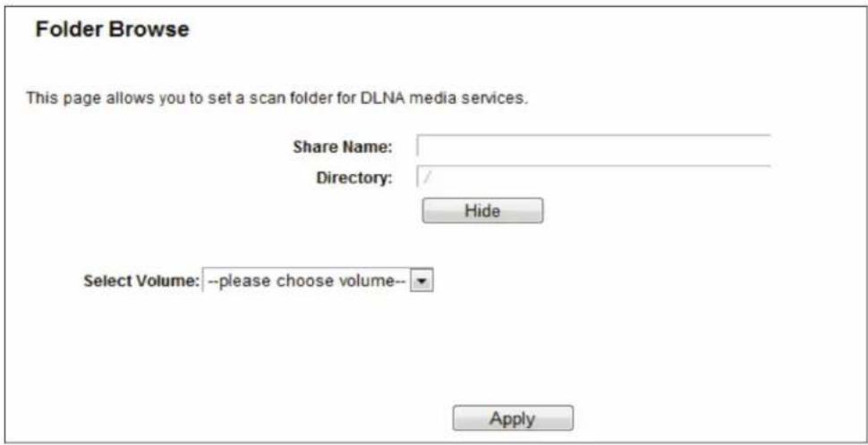
Figure 5-62. Folder Browse screen.
- Share Name—You can enter a display name for the share folder.
- Directory—Displays the location of this folder.
- Browse—Click the button to select the folder to share.
-
Apply—Click the button to save your settings.
-
Click the Scan Now button to scan all the share folders immediately. You can also select the Auto-scan, and at the same time, select an auto scan interval time from the drop-down list. In this case, the media server will auto scan the share folders.
NOTE: The max share folders number is 6. If you want to share a new folder when the number has reached 6, you can delete a shared folder and then add a new one.
5.11 NAT
Choose "NAT," then you can enable or disable the NAT and Hardware NAT Control feature. The NAT Rules and Hardware NAT will work properly only when the NAT Control feature is enabled.
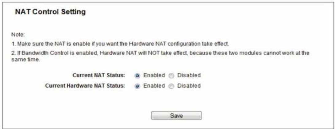
Figure 5-63. NAT Control Setting screen.
- Enable NAT Control—If enabled, the NAT function and the Forwarding configuration will take effect.
- Disable NAT Control—If disabled, neither NAT function nor Forwarding configuration will take effect.
- Enable Hardware NAT Control—If enabled, the Hardware NAT feature will take effect.
- Disable Hardware NAT Control—If disabled, neither Hardware NAT feature will take effect.
5.12 Forwarding
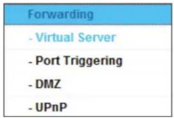
Figure 5-64. The Forwarding menu.
There are four submenus under the Forwarding menu: Virtual Servers, Port Triggering, DMZ, and UPnP. Click any of them, and you will be able to configure the corresponding function.
5.12.1 Virtual Servers
Choose "Forwarding Virtual Servers," then you can view and add virtual servers on this page. You can use virtual servers for setting up public services on your LAN. A virtual server is defined as a service port, and all requests from Internet to this service port will be redirected to the computer specified by the server IP. Any PC that was used for a virtual server must have a static or reserved IP address because its IP address may change when using the DHCP function. If you want the Virtual Servers configuration to take effect, make sure the NAT is enabled.
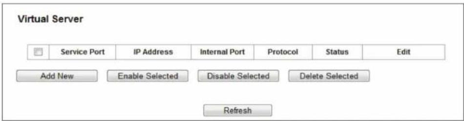
Figure 5-65. Virtual Servers.
- Service Port—The number of External Service Ports. You can enter a service port or a range of service ports (the format is XXX – YYY; XXX is the Start port and YYY is the End port).
- IP Address—The IP address of the PC running the service application.
- Internal Port—The Internal Service Port number of the PC running the service application. You can leave it blank if the Internal Port is the same as the Service Port, or enter a specific port number when Service Port is a single one.
- Protocol—The protocol used for this application, either TCP, UDP, or All (all protocols supported by the router).
- Status—The status of this entry, "Enabled," means the virtual server entry is enabled.
- Common Service Port—Some common services already exist in the drop-down list.
- Edit—To edit or delete an existing entry.
To setup a virtual server entry:
- Click the Add New button.
- Select the service you want to use from the Common Service Port list. If the Common Service Port menu does not list the service that you want to use, enter the number of the service port or service port range in the Service Port field.
- Enter the IP address of the computer running the service application in the IP Address field.
- Select the protocol used for this application in the Protocol drop-down list, either TCP, UDP, or All.
- Select the Enabled option in the Status drop-down list.
- Click the Save button.
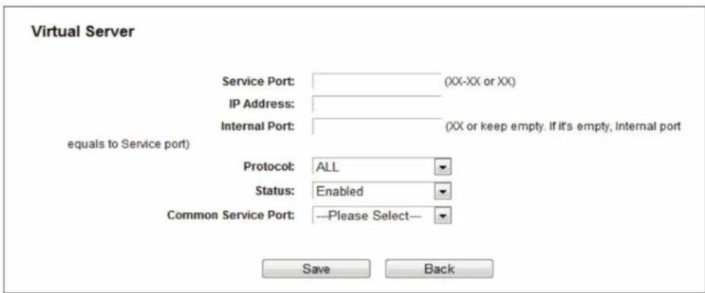
Figure 5-66. Add or Modify a Virtual Server Entry.
NOTE: You might have a computer or server that has more than one type of available service. If so, select another service, and type the same IP address for that computer or server.
To modify or delete an existing entry:
- Find the desired entry in the table.
- Click Edit or Delete as desired on the Edit column.
Click the Enable/Disable Selected button to make selected entries enabled/disabled.
Click the Delete Selected button to delete selected entries.
NOTE: If you set the service port of the virtual server as 80, you must set the Web management port on the Security Remote Management page to be any other value except 80 such as 8080. Otherwise, there will be a conflict to disable the virtual server.
5.12.2 Port Triggering
Choose "Forwarding Port Triggering," then you can view and add port triggering entry on this page (shown in Figure 5-67). Some applications require multiple connections, such as Internet games, video conferencing, Internet telephoning, and so on. You can use Port Triggering for applications that cannot work with a pure NAT router.
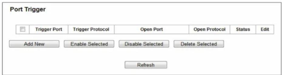
Figure 5-67. Port Triggering.
- Trigger Port—The port for outgoing traffic. An outgoing connection using this port will trigger this rule.
- Trigger Protocol—The protocol used for Trigger Ports, either TCP, UDP, or All (all protocols supported by the router).
- Open Port—The port or port range used by the remote system when it responds to the outgoing request. A response using one of these ports will be forwarded to the PC that triggered this rule. You can input up to 5 groups of ports (or port sections). Every group of ports must be separated with ",", for example, 2000–2038, 2046, 2050–2051, 2085, 3010–3030.
- Open Protocol—The protocol used for Open Port, either TCP, UDP, or ALL (all protocols supported by the router).
- Status—The status of this entry, Enabled means the Port Triggering entry is enabled.
- Edit—Modify or delete an existing entry.
- Common Applications—Some popular applications already listed in the drop-down list of Incoming Protocol.
To add a new rule, follow the steps below.
- Click the Add New button, then the next screen will pop-up.
- Select a common application from the Common Applications drop-down list, then the Trigger Port field and the Open Port field will be automatically filled. If the Common Applications do not have the application you need, enter the Trigger Port and the Open Port manually.
- Select the protocol used for Trigger Port from the Trigger Protocol drop-down list, either TCP, UDP, or All.
- Select the protocol used for Incoming Ports from the Open Protocol drop-down list, either TCP, UDP, or All.
- Select Enabled in the Status field.
- Click the Save button to save the new rule.
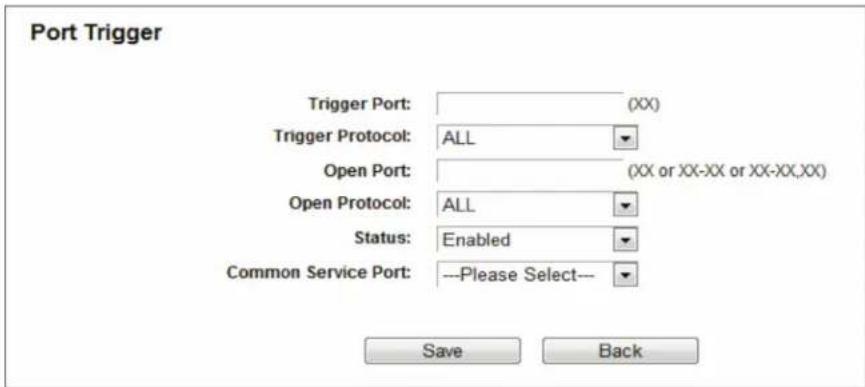
Figure 5-68. Add or Modify a Triggering Entry.
To modify or delete an existing entry:
- Find the desired entry in the table.
- Click Edit or Delete as desired in the Edit column.
Click the Enable Selected button to enable selected entries.
Click the Disable Selected button to disable selected entries.
Click the Delete Selected button to delete selected entries.
Once the router is configured, the operation is as follows:
- A local host makes an outgoing connection to an external host using a destination port number defined in the Trigger Port field.
- The router records this connection, opens the incoming port or ports associated with this entry in the Port Triggering table, and associates them with the local host.
- When necessary, the external host will be able to connect to the local host using one of the ports defined in the Open Ports field.
NOTES:
- When the trigger connection is released, the corresponding opened ports will be closed.
- Each rule can only be used by one host on the LAN at a time. The trigger connection of other hosts on the LAN will be refused.
- Open Ports ranges cannot overlap each other.
5.12.3 DMZ
Choose "Forwarding DMZ," then you can view and configure the DMZ host in the screen. The DMZ host feature allows one local host to be exposed to the Internet for a special-purpose service such as Internet gaming or videoconferencing. The router forwards packets of all services to the DMZ host. Any PC whose port is being forwarded must have its DHCP client function disabled and should have a new static IP Address assigned to it because its IP Address may be changed when using the DHCP function.
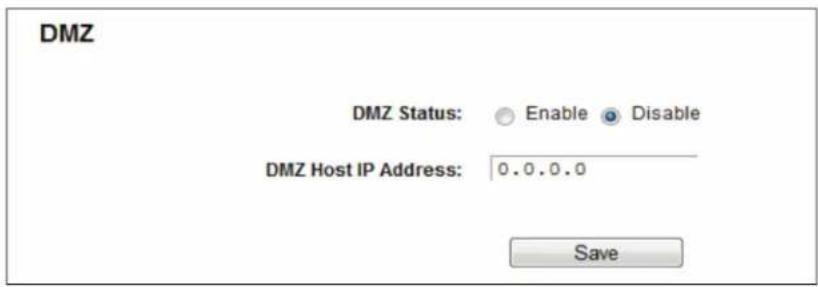
Figure 5-69. DMZ.
To assign a computer or server to be a DMZ server:
- Click the Enable button.
- Enter the IP address of a local PC that is set to be DMZ host in the DMZ Host IP Address field.
- Click the Save button.
5.12.4 UPnP
Choose "Forwarding UPnP," then you can view the information about UPnP in the screen. The Universal Plug and Play (UPnP) feature allows the devices, such as Internet computers, to access the local host resources or devices as needed. UPnP devices can be automatically discovered by the UPnP service application on the LAN.
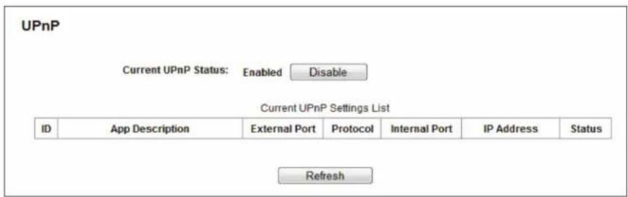
Figure 5-70. UPnP Setting.
- Current UPnP Status—UPnP can be enabled or disabled by clicking the Enable or Disable button. This feature is enabled by default.
- Current UPnP Settings List—This table displays the current UPnP information.
- App Description—The description about the application that initiates the UPnP request.
- External Port—The port that the router opened for the application.
- Protocol—The type of protocol that is opened.
- Internal Port - The port which the router opened for local host.
- IP Address—The IP address of the local host which initiates the UPnP request.
- Status—Either Enabled or Disabled. "Enabled" means that the port is still active; otherwise, the port is inactive.
Click the Enable button to enable UPnP.
Click the Disable button to disable UPnP.
Click the Refresh button to update the Current UPnP Settings List.
5.13 Security
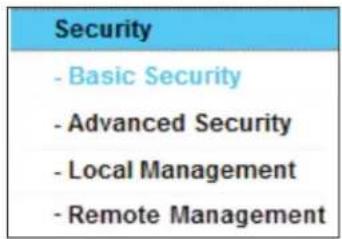
Figure 5-71. The Security menu.
There are four submenus under the Security menu: Basic Security, Advanced Security, Local Management and Remote Management. Click any of them, and you will be able to configure the corresponding functions.
5.13.1 Basic Security
Choose "Security Basic Security," then you can configure the basic security in the screen.
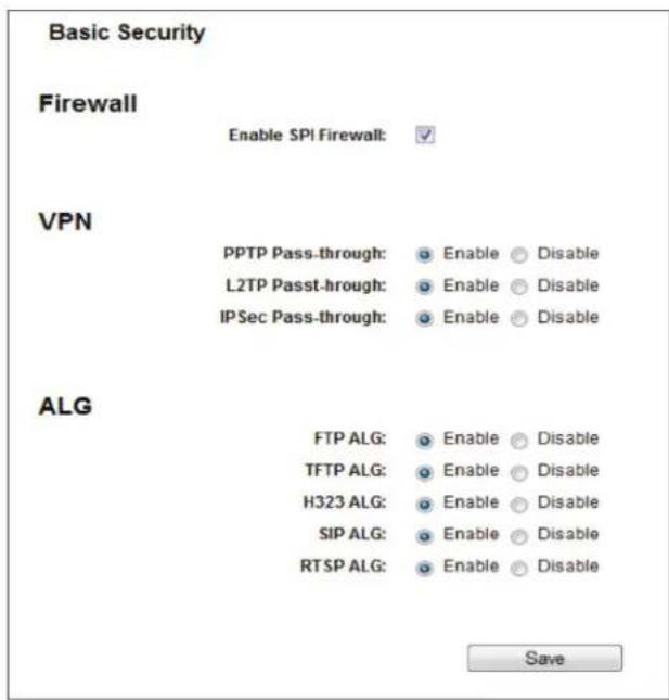
Figure 5-72. Basic Security.
- Firewall—A firewall protects your network from the outside world. Here you can enable or disable the router's firewall.
- SPI Firewall—SPI (Stateful Packet Inspection, also known as dynamic packet filtering) helps to prevent cyber attacks by tracking more state per session. It validates that the traffic passing through the session conforms to the protocol. SPI Firewall is enabled by factory default. If you want all the computers on the LAN exposed to the outside world, you can disable it.
- VPN—VPN Passthrough must be enabled if you want to allow VPN tunnels using VPN protocols to pass through the router.
- PPTP Passthrough—Point-to-Point Tunneling Protocol (PPTP) allows the Point-to-Point Protocol (PPP) to be tunneled through an IP network. To allow PPTP tunnels to pass through the router, click Enable.
- L2TP Passthrough—Layer Two Tunneling Protocol (L2TP) is the method used to enable Point-to-Point sessions via the Internet on the Layer Two level. To allow L2TP tunnels to pass through the router, click Enable.
- IPSec Passthrough—Internet Protocol security (IPSec) is a suite of protocols for ensuring private, secure communications over Internet Protocol (IP) networks, through the use of cryptographic security services. To allow IPSec tunnels to pass through the router, click Enable.
- ALG—We recommend that you enable Application Layer Gateway (ALG) because ALG allows customized Network Address Translation (NAT) traversal filters to be plugged into the gateway to support address and port translation for certain application layer "control/data" protocols such as FTP, TFTP, H323, etc.
- FTP ALG—To allow FTP clients and servers to transfer data across NAT, click Enable.
- TFTP ALG—To allow TFTP clients and servers to transfer data across NAT, click Enable.
- H323 ALG—To allow Microsoft NetMeeting clients to communicate across NAT, click Enable.
- SIP ALG—To allow SIP clients and servers to communicate across NAT, click Enable.
- RTSP ALG—To allow some media player clients to communicate with some streaming media servers across NAT, click Enable.
Click the Save button to save your settings.
5.13.2 Advanced Security
Choose "Security Advanced Security," then you can protect the router from being attacked by TCP-SYN Flood, UDP Flood, and ICMP-Flood.
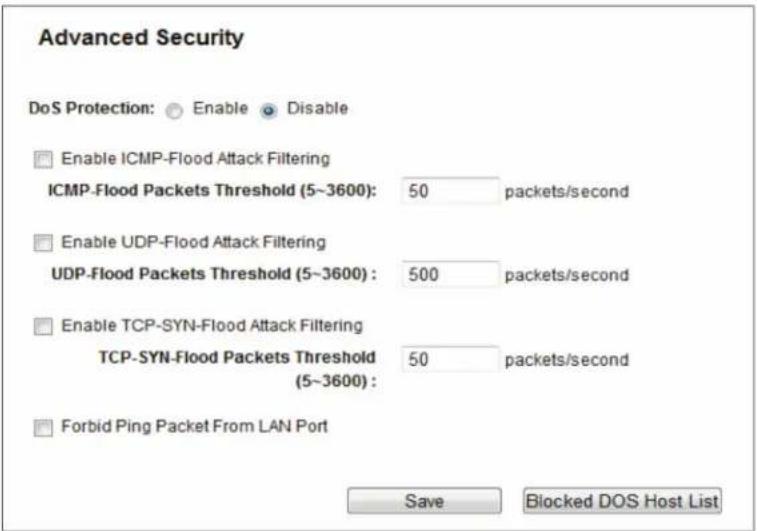
Figure 5-73. Advanced Security.
- DoS Protection—Denial of Service protection. Check the Enable or Disable button to enable or disable the DoS protection function. Only when it is enabled will the flood filters be enabled.
NOTE: DoS Protection will take effect only when the Traffic Statistics in "System Tool Statistics" is enabled.
- Enable ICMP-FLOOD Attack Filtering—Enable or Disable the ICMP-FLOOD Attack Filtering.
- ICMP-FLOOD Packets Threshold (5–3600):—The default value is 50. Enter a value between 5–3600. When the current ICMP-FLOOD Packets number is beyond the set value, the router will startup the blocking function immediately.
- Enable UDP-FLOOD Filtering—Enable or Disable the UDP-FLOOD Filtering.
- UDP-FLOOD Packets Threshold (5–3600)—The default value is 500. Enter a value between 5–3600. When the current UPD-FLOOD Packets number is beyond the set value, the router will start up the blocking function immediately.
- Enable TCP-SYN-FLOOD Attack Filtering—Enable or Disable the TCP-SYN-FLOOD Attack Filtering.
- TCP-SYN-FLOOD Packets Threshold (5–3600)—The default value is 50. Enter a value between 5–3600. When the current TCP-SYN-FLOOD Packets numbers is beyond the set value, the router will start up the blocking function immediately.
- Forbid Ping Packet From LAN Port—Enable or Disable Forbid Ping Packet From LAN Port. The default setting is disabled. If enabled, the ping packet from LAN cannot access the router. This function can be used to defend against some viruses.
Click the Save button to save the settings.
Click the Blocked DoS Host List button to display the DoS host table by blocking.
5.13.3 Local Management
Choose "Security Local Management," then you can configure the management rule in the screen. The management feature allows you to deny computers in a LAN from accessing the router.
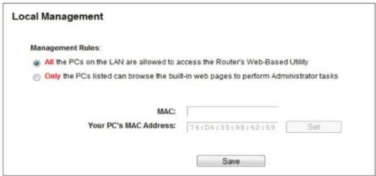
Figure 5-74. Local Management.
By default, the radio button "All the PCs on the LAN are allowed to access the Router's Web-Based Utility" is checked. If you want to allow PCs with specific MAC Addresses to access the Setup page of the router's Web-Based Utility locally from inside the network, check the radio button "Only the PCs listed can browse the built-in web pages to perform Administrator tasks," and then enter each MAC Address in a separate field. The format for the MAC Address is XX:XX:XX:XX:XX:XX (X is any hexadecimal digit). Only the PCs with MAC address listed can use the password to browse the built-in web pages to perform Administrator tasks while all the others will be blocked.
After you click the Add button, your PC's MAC Address will be placed in the list above.
Click the Save button to save your settings.
NOTE: If your PC is blocked but you want to access the router again, use a pin to press and hold the WPS/Reset button (hole) on the back panel for about 5 seconds to reset the router's factory defaults on the router's Web-Based Utility.
5.13.4 Remote Management
Choose "Security —> Remote Management," then you can configure the Remote Management function in the screen. This feature allows you to manage your router from a remote location via the Internet.
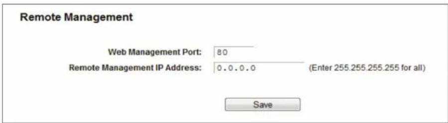
Figure 5-75. Remote Management.
- Web Management Port—Web browser access normally uses the standard HTTP service port 80. This router's default remote management web port number is 80. For greater security, you can change the remote management web port to a custom port by entering that number in the box provided. Choose a number between 1024 and 65535 but do not use the number of any common service port.
- Remote Management IP Address—This is the current address you will use when accessing your router from the Internet. This function is disabled when the IP address is set to the default value of 0.0.0.0. To enable this function, change 0.0.0.0 to a valid IP address. If set to 255.255.255.255, then all the hosts can access the router from the internet.
NOTES:
- To access the router, type your router's WAN IP address into your browser's address (in IE) or Location (in Navigator) box, followed by a colon and the custom port number. For example, if your router's WAN address is 202.96.12.8, and the port number used is 8080, enter http://202.96.12.8:8080 in your browser. Later, you may be asked for the router's password. After successfully entering the username and password, you will be able to access the router's web-based utility.
- Be sure to change the router's default password to a very secure password.
5.14 Parent Control
Choose menu "Parent Control," then you can configure the parent control in the screen. The Parent Control function can be used to control the Internet activities of the child, limit the child to access certain websites, and restrict the surfing time.
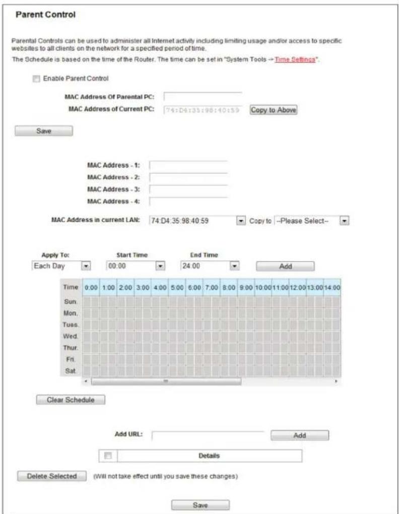
Figure 5-76. Parent Control Settings.
- Parent Control—Check Enable if you want this function to take effect; otherwise, check Disable.
- MAC Address of the Parental PC—In this field, enter the MAC address of the controlling PC, or you can use the Copy To Above button.
- MAC Address of Current PC—This field displays the MAC address of the PC that is managing this router. If the MAC Address of your adapter is registered, you can click the Copy To Above button to fill this address to the MAC Address of Parental PC field above.
Click the Save button to make your settings take effect.
To add a new entry, follow the steps below.
- Check the Enable Parent Control box.
- Enter the MAC address of the PC (e.g. 00:11:22:33:44:AA) you want to control in the MAC Address 1–4 field, or you can choose the MAC address from the MAC Address in the current LAN drop-down list.
-
Enter the allowed domain name of the website, either the full name or the keywords (e.g. google) in the Add URL field. Any domain name with keywords in it (www.google.com, www.google.com.hk) will be allowed. Click the Add button.
-
Set the time period allowed for the PC controlled to access the Internet. For detailed information, go to "Access Control Schedule."
- Click the Save button.
Click the Delete Selected button to delete the selected entries in the table.
For example: If you want the child PC with MAC address 00:11:22:33:44:AA to access www.google.com on Saturday only while the parent PC with MAC address 00:11:22:33:44:BB is without any restriction, follow the settings below.
- Click the "Parent Control" menu on the left to enter the Parent Control Settings page. Check Enable and enter the MAC address 00:11:22:33:44:BB in the MAC Address of Parental PC field.
- Click the "Parent Control" menu on the left to go back to the Add or Modify Parent Control Entry page:
2a. Enter 00:11:22:33:44:AA in the MAC Address 1 field.
2b. Create a new schedule with Day is Sat and Time is all day-24 hours. Click Add.
2c. Enter "www.google.com" in the Add URL field. Click Add.
3. Click Save to complete the settings.
Then you will see the next page.
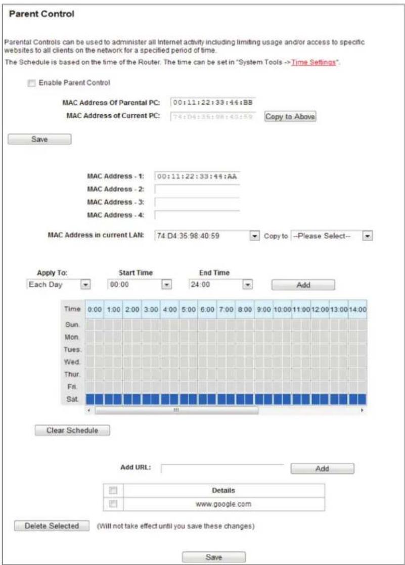
Figure 5-77. Parent Control Settings.
5.15 Access Control
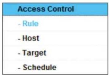
Figure 5-78. Access Control.
There are four submenus under the Access Control menu: Rule, Host, Target, and Schedule. Click any of them, and you will be able to configure the corresponding function.
5.15.1 Rule
Choose "Access Control Rule," then you can view and set Access Control rules in the screen.
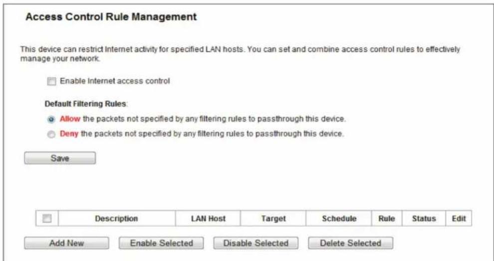
Figure 5-79. Access Control Rule Management.
- Enable Internet Access Control—Select the check box to enable the Internet Access Control function, so the Default Filter Policy can take effect.
- Description—Displays the name of the rule and this name is unique.
• LAN Host—Displays the host selected in the corresponding rule. - Target—Displays the target selected in the corresponding rule.
- Schedule—Displays the schedule selected in the corresponding rule.
- Enable—Displays the status of the rule, enabled or not. Check this option to enable a specific entry.
- Edit—Edit or delete an existing rule.
- Add New—Click the Add New button to add a new rule entry.
- Enable Selected—Click the Enable Selected button to enable selected rules in the list.
- Disable Selected—Click the Disable Selected button to disable selected rules in the list.
- Delete Selected—Click the Delete Selected button to delete selected entries in the table.
How to add a new rule:
- Click the Add New button and the next screen will pop up.
- Give a name (e.g. Rule_1) for the rule in the Description field.
- Select a host from the LAN Host drop-down list or click "Add LAN Host."
- Select a target from the Target drop-down list or click "Add Target."
- Select a schedule from the Schedule drop-down list or click "Add Schedule."
- In the Status field, select Enabled or Disabled to enable or disable your entry.
- In the Direction field, select IN or OUT.
-
Select a schedule from the Protocol drop-down list.
-
Click the Save button.
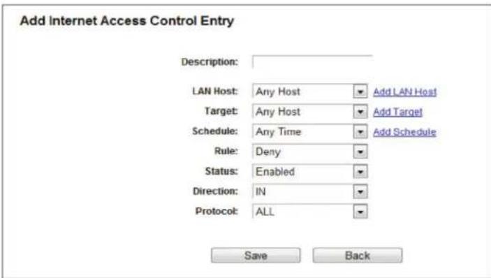
Figure 5-80. Add Internet Access Control Entry.
For example: To allow the host with MAC address 00 : 11 : 22 : 33 : 44 : AA to access www.google.com only from 18:00 to 20:00 on Saturday and Sunday, and forbid other hosts in the LAN to access the Internet, follow the settings below:
- Click the submenu Rule of Access Control in the left to return to the Rule List page. Select Enable Internet Access Control and choose "Allow the packets specified by any enabled access control policy to pass through the router."
- We recommend that you click Add New button to finish all the following settings.
- Click the submenu Host of Access Control in the left to enter the Host List page. Add a new entry with the Host Description as Host_1 and MAC Address as 00:11:22:33:44:AA.
- Click the submenu Target of Access Control in the left to enter the Target List page. Add a new entry with the Target Description as Target_1 and Domain Name as www.google.com.
- Click the submenu Schedule of Access Control in the left to enter the Schedule List page. Add a new entry with the Schedule Description as Schedule_1, Day is Sat and Sun, Start Time as 1800 and Stop Time as 2000.
- Click the submenu Rule of Access Control in the left, Click Add New button to add a new rule as follows:
6a. In the Rule Name field, create a name for the rule.
NOTE: This name should be unique, for example Rule_1.
6b. In the Host field, select Host_1.
6c. In the Target field, select Target_1.
6d. In the Schedule field, select Schedule_1.
6e. In the Status field, select Enabled.
6f. Click Save to complete the settings.
Then you will go back to the Access Control Rule Management page and see the following list.

Figure 5-81. Rule list.
5.15.2 Host
Choose "Access Control Host," then you can view and set a Host list in the screen. The host list is necessary for the Access Control Rule.
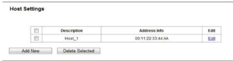
Figure 5-82. Host Settings.
- Description—Displays the description of the host and this description is unique.
- Address Info—Displays the information about the host. It can be IP or MAC.
- Edit—Modify or delete an existing entry.
Click the Delete Selected button to delete the selected entries in the table.
To add a new entry, follow the steps below.
- Click the Add New button.
- In the Mode field, select IP Address or MAC Address.
2a. If you select IP Address, the screen shown is Figure 5-83.
- In the Description field, create a unique description for the host (e.g. Host_1).
- In the IP Address field, enter the IP address.
2b. If you select MAC Address, the screen shown is Figure 5-84.
- In the Description field, create a unique description for the host (e.g. Host_1).
- In the MAC Address field, enter the MAC address.
- Click the Save button to complete the settings.
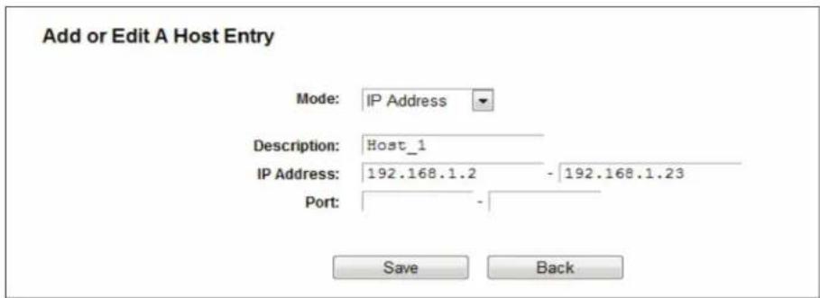
Figure 5-83. Add or Modify a Host Entry.
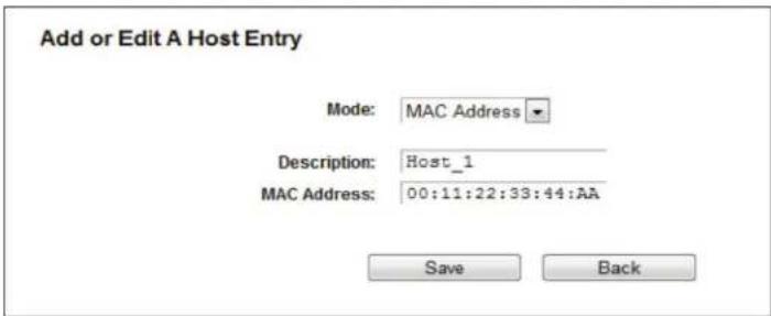
Figure 5-84. Add or Modify a Host Entry.
For example: To restrict the internet activities of host with MAC address 00:11:22:33:44:AA, follow the settings below:
- Click the Add New button in the Host Settings page to enter the Add or Modify a Host Entry page.
- In the Mode field, select MAC Address from the drop-down list.
- In the Description field, create a unique description for the host (e.g. Host_1).
- In the MAC Address field, enter 00:11:22:33:44:AA.
- Click Save to complete the settings.
Then you will go back to the Host Settings page and see the following list.
| Description | Address Info | Edit |
| Host_1 | 00:11:22:33:44:AA | Edit |
Figure 5-85. Host list.
5.15.3 Target
Choose "Access Control —> Target," then you can view and set a Target list in the next screen. The target list is necessary for the Access Control Rule.
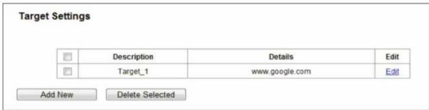
Figure 5-86. Target Settings.
- Description—Displays the description about the target and this description is unique.
- Details—The target can be IP address, port, or domain name.
- Edit—Modify or delete an existing entry.
To add a new entry, follow the steps below.
- Click the Add New button.
- In the Mode field, select IP Address, MAC Address, or URL Address.
2a. If you select IP Address, the next screen appears.
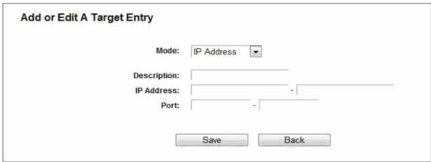
Figure 5-87. Add or Modify an Access Target Entry.
I) In the Description field, create a unique description for the target (e.g., Target_1).
II) In the IP Address field, enter the IP address of the target.
III) Specify the Target Port manually.
2b. If you select MAC Address, the next screen appears.
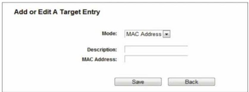
Figure 5-88. Add or Modify an Access Target Entry.
I) In Description field, create a unique description for the target (e.g. Target_1).
II) In IP Address field, enter the IP address of the target.
III) Specify the Target Port manually.
2c. If you select URL Address, the screen shown is Figure 4 82.
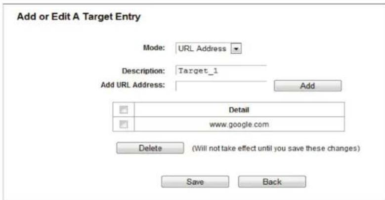
Figure 5-89. Add or Modify an Access Target Entry.
I) In the Description field, create a unique description for the target (e.g. Target_1).
II) In the Add URL Address field, enter the domain name, either the full name or the keywords (for example, google) in the blank. Any domain name with keywords in it (www.google.com, www.google.cn) will be blocked or allowed. Click Add to save the address.
- Click the Save button.
Click the Delete Selected button to delete the selected entries in the table.
For example: To restrict the internet activities of host with MAC address 00:11:22:33:44:AA in the LAN to access www.google.com only, follow the settings below:
-
Click Add New button in Figure 4 79 to enter the Add or Modify an Access Target Entry page.
-
In Mode field, select URL Address from the drop-down list.
-
In Description field, create a unique description for the target (e.g. Target_1).
-
In Add URL Address field, enter www.google.com. And then click Add to save the entry.
-
Click Save to complete the settings.
Then you will go back to the Target Settings page and see the following list.
| ☐ | Description | Details | Edit |
| ☐ | Target_1 | www.google.com | Edit |
Figure 5-90. Target setting list.
5.15.4 Schedule
Choose "Access Control Schedule," then you can view and set a Schedule list in the next screen. The Schedule list is necessary for the Access Control Rule.
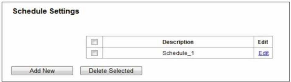
Figure 5-91. Schedule Settings.
- Description—Displays the description of the schedule and this description is unique.
- Edit—Edit or delete an existing schedule.
To add a new schedule, follow the steps below:
- Click the Add New button and the next screen will pop-up.
- In Description field, create a unique description for the schedule (e.g. Schedule_1).
- Select the Day or days from the drop-down list. And then select the Start Time and Stop Time from the drop-down list. Click Add to save the entry.
- Click Save to complete the settings.
Click the Delete Selected button to delete selected entries in the table.
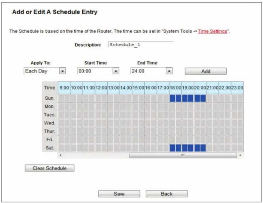
Figure 5-92. Advanced Schedule Settings.
For example: If you desire to restrict the internet activities of host with MAC address 00:11:22:33:44:AA to access www.google.com only from 18:00 to 20:00 on Saturday and Sunday, follow the steps below:
- Click the Add New button to enter the Advanced Schedule Settings page.
- In the Description field, create a unique description for the schedule (e.g. Schedule_1).
- In the Day list, select Each Week from the drop-down list and click Sat and Sun.
- In the Time list, select 18:00 for Start Time field and 20:00 for Stop Time. And then click the Add button.
- Click Save to complete the settings.
5.16 Advanced Routing
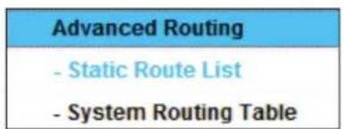
Figure 5-93. Advanced Routing.
There are two submenus under the Advanced Routing menu: Static Route List and System Routing Table. Click either of them, and you will be able to configure the corresponding function.
5.16.1 Static Route List
Choose "Advanced Routing —> Static Route List," then you can configure the static route in the next screen. A static route is a pre-determined path that network information must travel to reach a specific host or network.
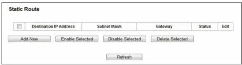
Figure 5-94. Static Route.
To add static route entries:
- Click Add New, and you will see the following screen.
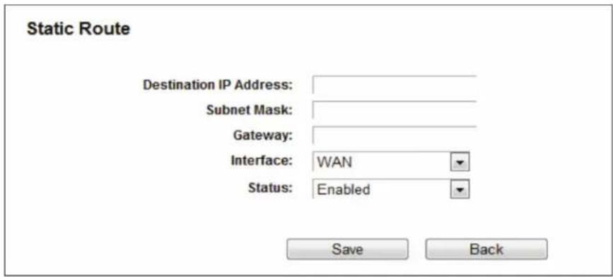
Figure 5-95. Add or Modify a Static Route Entry.
- Enter the following data:
- Destination IP Address—The Destination IP Address is the address of the network or host that you want to assign to a static route.
- Subnet Mask—The Subnet Mask determines which portion of an IP Address is the network portion, and which portion is the host portion.
- Gateway—This is the IP Address of the gateway device that allows for contact between the router and the network or host.
-
Select Enabled or Disabled for this entry on the Status drop-down list.
-
Click the Save button to make the entry take effect.
Other configurations for the entries:
Click the Delete button to delete the entry.
Click the Enable Selected button to enable the selected entries.
Click the Disable Selected button to disable the selected entries.
Click the Delete Selected button to delete the selected entries.
5.16.2 System Routing Table
Choose "Advanced Routing —> System Routing Table," then you can view the System Routing Table in the next screen. System routing table views all of the valid route entries in use. The Destination IP address, Subnet Mask, Gateway, and Interface will be displayed for each entry.

Figure 5-96. System Routing Table.
- Destination Network—The Destination Network is the address of the network or host to which the static route is assigned.
- Subnet Mask—The Subnet Mask determines which portion of an IP address is the network portion, and which portion is the host portion.
- Gateway—This is the IP address of the gateway device that allows for contact between the router and the network or host.
- Interface—This interface tells you either the Destination IP Address is on the LAN and WLAN (internal wired and wireless networks), or on the WAN (Internet).
5.17 Bandwidth Control
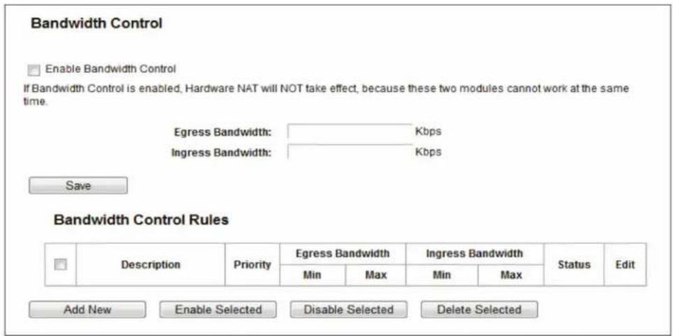
Figure 5-97. Bandwidth Control.
Choose "Bandwidth Control," then you can configure the bandwidth control in the screen as shown next.
You can configure the Egress Bandwidth and Ingress Bandwidth in this page. Their values you configure should be less than 100000Kbps. You can also view and configure the Bandwidth Control rules in this page.
- Enable Bandwidth Control—Check this box so that the Bandwidth Control settings can take effect.
- Egress Bandwidth—The upload speed through the WAN port.
- Ingress Bandwidth—The download speed through the WAN port.
Click Save to make the settings take effect.
- Description—This is the information about the rules such as address range.
- Priority—The priority of the rule, ranging from 1 to 8. 1 stands for the highest priority.
- Egress bandwidth—This field displays the max and mix upload bandwidth through the WAN port; the default is 0.
- Ingress bandwidth—This field displays the max and mix download bandwidth through the WAN port; the default is 0.
• Status—This displays the status of the rule. - Edit—Click Edit to edit the rule. Click Delete to delete the rule.
To add/modify a Bandwidth Control rule, follow the steps below.
- Click Add New in the Bandwidth Control screen, and you will see a new screen shown next.
- Enter the information in the screen shown below.
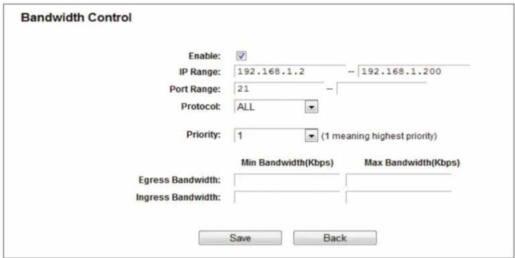
Figure 5-98. Bandwidth Control Rule Settings.
- Click the Save button.
5.18 IP and MAC Binding
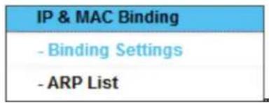
Figure 5-99. IP and MAC Binding menu
There are two submenus under the IP & MAC Binding menu: Binding Settings and ARP List. Click either of them, and you will be able to scan or configure the corresponding function. Detailed explanations for each submenu are provided below.
5.18.1 Binding Settings
This page displays the IP & MAC Binding Setting table.
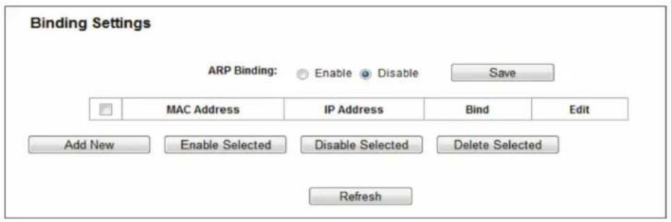
Figure 5-100. Binding Setting.
• MAC Address—The MAC address of the controlled computer in the LAN.
- IP Address—The assigned IP address of the controlled computer in the LAN.
- Bind—Check this option to enable ARP binding for a specific device.
- Edit—Edit or delete an existing entry.
When you want to add or modify an IP & MAC Binding entry, you can click the Add New button or Edit button, and then you will go to the next page. This page is used for adding or modifying an IP & MAC Binding entry.
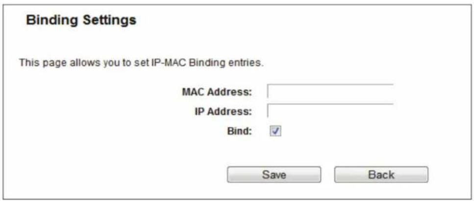
Figure 5-101. IP & MAC Binding Setting (Add & Modify).
To add IP & MAC Binding entries, follow the steps below.
- Click the Add New button as shown in Figure 5-100.
- Enter the MAC Address and IP Address.
- Select the Bind checkbox.
- Click the Save button to save it.
To modify or delete an existing entry, follow the steps below.
- Find the desired entry in the table.
- Click Edit or Delete in the Edit column.
5.18.2 ARP List
To manage the computer, you can observe the computers in the LAN by checking the relationship of MAC address and IP address on the ARP list, and you can also configure the items on the ARP list. This page displays the ARP List; it shows all the existing IP & MAC Binding entries.
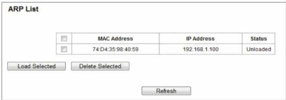
Figure 5-102. ARP List.
-
MAC Address—The MAC address of the controlled computer in the LAN.
-
IP Address—The assigned IP address of the controlled computer in the LAN.
-
Status—Indicates whether or not the MAC and IP addresses are bound.
Click the Load Selected button to load the selected items to the IP & MAC Binding list.
Click the Delete Selected button to delete the selected items from the IP & MAC Binding list.
Click the Refresh button to refresh all items.
NOTE: An item cannot be loaded to the IP & MAC Binding list if the IP address of the item has been loaded before. You will see an error warning prompt. "Load All" only loads the items that do not interfere with the IP & MAC Binding list.
5.19 Dynamic DNS
Choose "Dynamic DNS," then you can configure the Dynamic DNS function.
The router offers the DDNS (Dynamic Domain Name System) feature, which allows the hosting of a website, FTP server, or e-mail server with a fixed domain name (named by you) and a dynamic IP address, and then your friends can connect to your server by entering your domain name no matter what your IP address is. Before using this feature, you need to sign up for DDNS service providers such as www.comexe.cn, www.dyndns.org, or www.no-ip.com. The Dynamic DNS client service provider will give you a password or key.
5.19.1 No -ip.com DDNS
If the dynamic DNS Service Provider you select is www.no-ip.com, the page will appear as shown next.
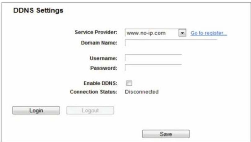
Figure 5-103. No-ip.com DDNS Settings.
To set up for DDNS, follow these instructions:
-
Enter the Domain Name you received from dynamic DNS service provider.
-
Enter the Username for your DDNS account.
-
Enter the Password for your DDNS account.
-
Enable DDNS.
-
Click the Login button to login to the DDNS service.
Connection Status—The status of the DDNS service connection is displayed here.
Click Logout to log out from the DDNS service.
NOTE: If you want to login again with another account after a successful login, click the Logout button, then input your new username and password and click the Login button.
5.19.2 Comexe.cn DDNS
If the dynamic DNS Service Provider you select is www.comexe.cn, the next page will appear.
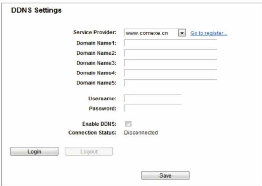
Figure 5-104. Comexe.cn DDNS Settings.
To set up for DDNS, follow these instructions:
- Enter the Domain Name your dynamic DNS service provider gave you.
- Enter the Username for your DDNS account.
- Enter the Password for your DDNS account.
- Enable DDNS.
- Click the Login button to log in to the DDNS service.
Connection Status—The status of the DDNS service connection is displayed here.
Click Logout to log out from the DDNS service.
NOTE: If you want to login again with another account after a successful login, click the Logout button, then input your new username and password and click the Login button.
5.19.3 Dyndns.com DDNS
If the dynamic DNS Service Provider you select is www.dyndns.com, the page will appear as shown next.
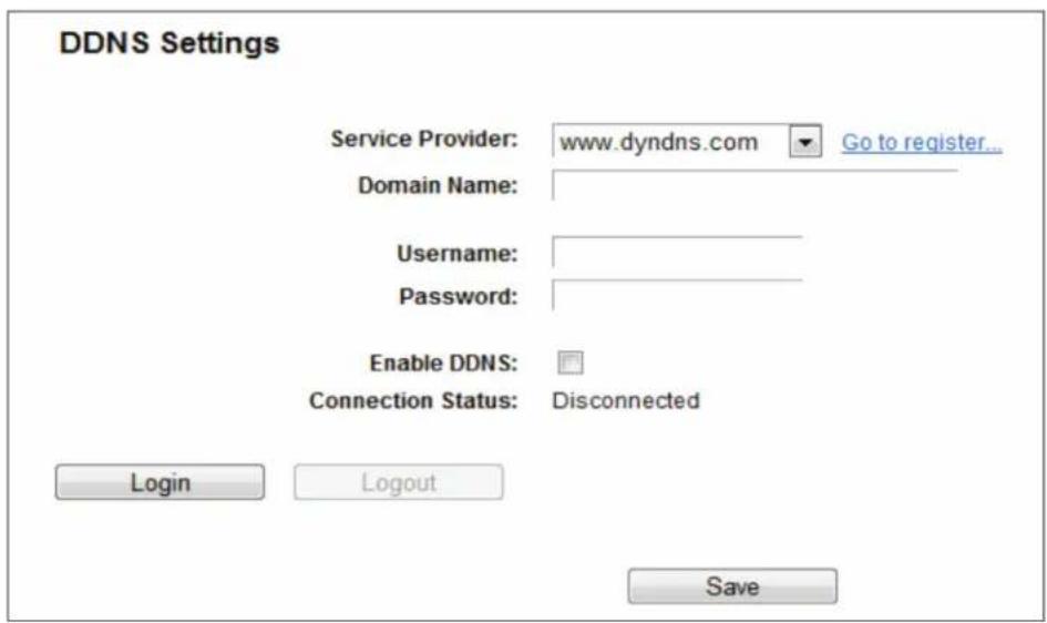
Figure 5-105. Dyndns.org DDNS Settings.
To set up for DDNS, follow these instructions:
-
Enter the Domain Name you received from the dynamic DNS service provider.
-
Enter the Username for your DDNS account.
-
Enter the Password for your DDNS account.
-
Enable DDNS.
-
Click the Login button to login to the DDNS service.
Connection Status—The status of the DDNS service connection is displayed here.
Click Logout to log out from the DDNS service.
NOTE: If you want to login again with another account after a successful login, click the Logout button, then input your new username and password and click the Login button.
5.20 IPv6
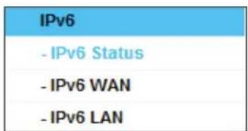
Figure 5-106. IPv6 Support.
There are three submenus under the IPv6 Support menu: IPv6 Status, IPv6 WAN and IPv6 LAN. Click either of them, and you will be able to scan or configure the corresponding function. The detailed explanations for each submenu are provided below.
5.20.1 IPv6 Status
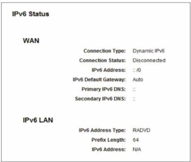
Figure 5-107. IPv6 Status.
The IPv6 Status page displays the router's current IPv6 status and configuration. All information is read-only.
• WAN
- Connection Type—The IPv6 connection for the WAN.
- Connection Status—The status of the IPv6 connection.
- IPv6 Address—The WAN IPv6 address.
- IPv6 Default Gateway—The router's default gateway.
- Primary IPv6 DNS—The primary IPv6 DNS address.
- Secondary IPv6 DNS—The secondary IPv6 DNS address.
• LAN
- IPv6 Address Type—There are two types of assignments for the IPv6 address: RADVD (Stateless address auto-configuration) and DHCPv6 (Dynamic Host Configuration Protocol for IPv6) Server.
- Prefix Length—The prefix length of the IPv6 address.
- IPv6 Address—The LAN IPv6 address.
5.20.2 IPv6 WAN
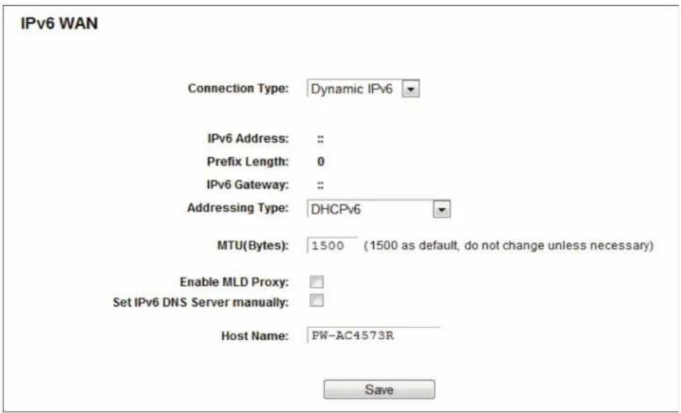
Figure 5-108. Enable/Disable IPv6.
- Connection Type - Choose the correct WAN connection type based on your ISP network topology.
- Dynamic IPv6—Connections that use dynamic IPv6 address assignment.
- Static IPv6—Connections that use static IPv6 address assignment.
- PPPoEv6—Connections that use PPPoEV6 that requires a user name and password.
- Tunnel 6to4—Connections that use 6to4 address assignment.
Different types of WAN connections require you to do different settings. Below are the detailed explanations for the respective type.
- Dynamic IPv6
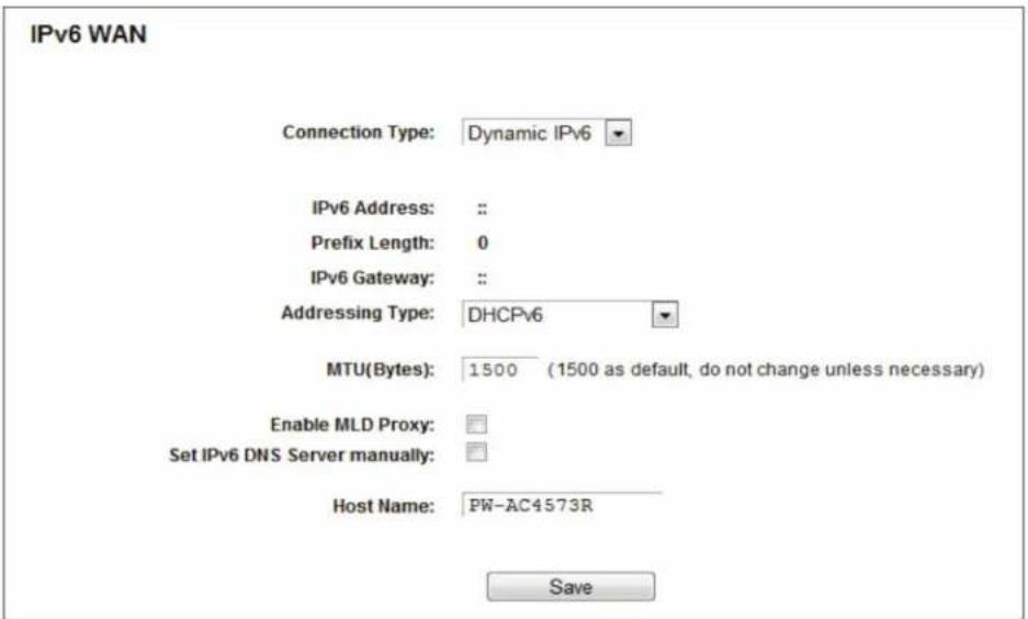
Figure 5-109. Dynamic IPv6.
- IPv6 Address—The IPv6 address assigned by your ISP dynamically.
- Prefix Length—The length of IPv6 address prefix.
- IPv6 Gateway—Enter the default gateway provided by your ISP.
- Addressing Type—There are two types of assignments for the IPv6 address: SLAAC (Stateless address auto-configuration) and DHCPv6 (Dynamic Host Configuration Protocol for IPv6) Server.
- MTU(Bytes)—The normal MTU (Maximum Transmission Unit) value for most Ethernet networks is 1500 Bytes. For some ISPs, you may need to modify the MTU. But this is rarely required, and should not be done unless you are sure it is necessary for your ISP connection.
If your ISP gives you one or two DNS IPv6 addresses, select Set IPv6 DNS Server manually and enter the IPv6 DNS Server and Secondary IPv6 DNS Server into the correct fields. Otherwise, the DNS servers will be assigned from the ISP dynamically.
- Enable MLD Proxy—Enable the Multicast Listener Discovery (MLD) Proxy function if you need it.
- IPv6 DNS Server—Enter the DNS IPv6 address provided by your ISP.
- Secondary IPv6 DNS Server—Enter another DNS IPv6 address provided by your ISP.
NOTE: If you get an Address not found error when you access a Web site, your DNS servers might not be set up properly. Contact your ISP to get DNS server addresses.
- Static IPv6
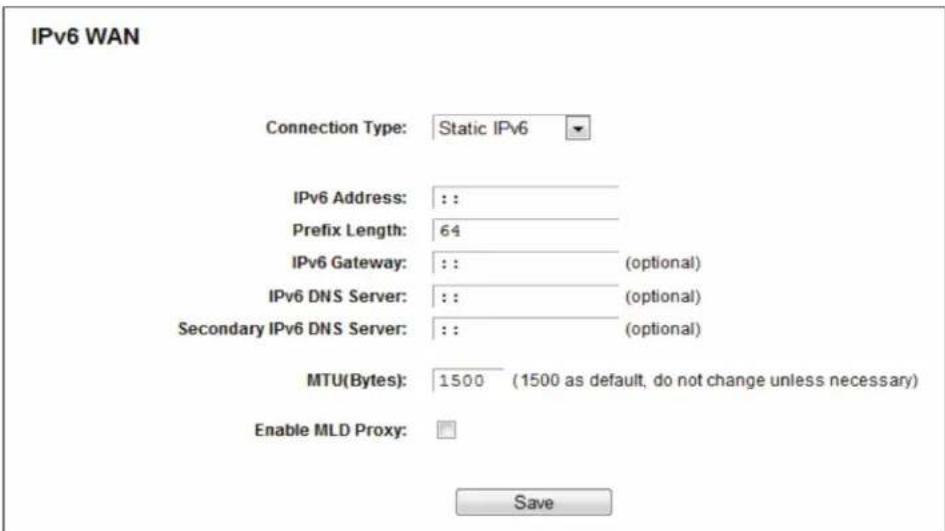
Figure 5-110. Static IPv6.
- IPv6 Address—Enter the IPv6 address provided by your ISP.
- Prefix Length—The length of IPv6 address prefix.
- IPv6 Gateway—Enter the default gateway provided by your ISP.
- IPv6 DNS Server—Enter the DNS IPv6 address provided by your ISP.
- Secondary IPv6 DNS Server—Enter another DNS IPv6 address provided by your ISP.
- MTU (Bytes)—The normal MTU (Maximum Transmission Unit) value for most Ethernet networks is 1500 Bytes. For some ISPs, you may need to modify the MTU. But this is rarely required, and should not be done unless you are sure it is necessary for your ISP connection.
- Enable MLD Proxy—Enable the Multicast Listener Discovery (MLD) Proxy function if you need it.
- PPPoEv6
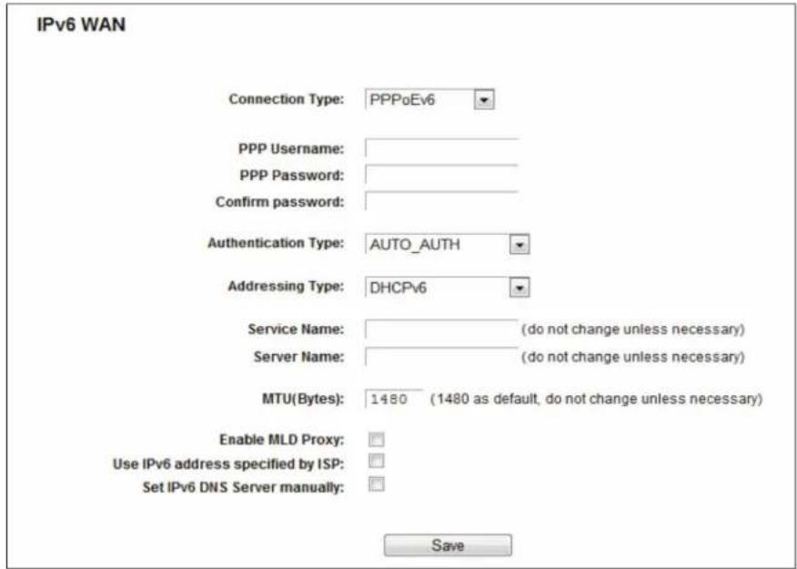
Figure 5-111. PPPoEv6.
- PPP Username/Password—Enter the User Name and Password provided by your ISP. These fields are case-sensitive.
- Authentication Type—Choose one authentication type from AUTO-AUTH, PAP, CHAP, and MS-CHAP.
- Addressing Type—There are two types of assignments for the IPv6 address: SLAAC (Stateless address auto-configuration) and DHCPv6 (Dynamic Host Configuration Protocol for IPv6) Server.
- MTU (Bytes)—The normal MTU (Maximum Transmission Unit) value for most Ethernet networks is 1500 Bytes. For some ISPs, you may need to modify the MTU. But this is rarely required, and should not be done unless you are sure it is necessary for your ISP connection.
- Enable MLD Proxy—Enable the Multicast Listener Discovery (MLD) Proxy function if you need it.
- Use the IP address specified by the ISP—Input a static IPv6 address from the ISP.
-
Set the IPv6 DNS Server manually—Enter the IP address of the IPv6 DNS server and secondary IPv6 DNS server.
-
Tunnel 6to4
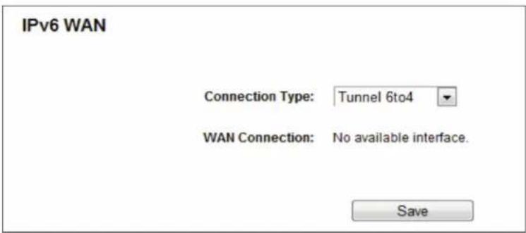
Figure 5-112. Tunnel 6to4.
This type is used when your WAN connection is IPv4 and the LAN connection is IPv6.
- WAN Connection - Display the available wan connection.
Click the Save button to save your settings.
5.20.3 IPv6 LAN
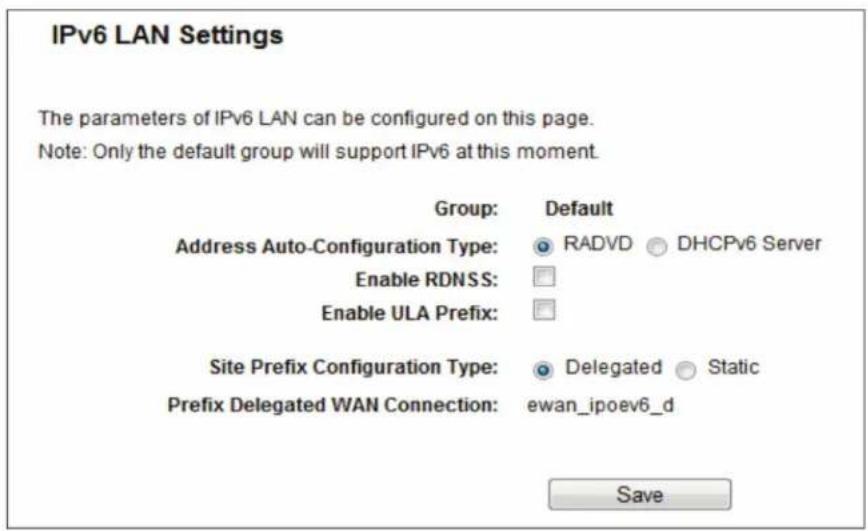
Figure 5-113. IPv6 LAN.
- Address Auto-Configuration Type—Choose the IPv6 address auto-configuration type, either RADVD or DHCPv6 Server.
- Site Prefix Configuration Type—Choose the site prefix configuration type, either Delegated or Static.
5.21 System Tools
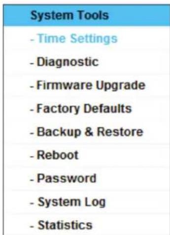
Figure 5-114. The System Tools menu.
Choose "System Tools," then you can see the submenus under the main menu: Time Settings, Diagnostic, Firmware Upgrade, Factory Defaults, Backup & Restore, Reboot, Password, System Log and Statistics. Click any of them, and you will be able to configure the corresponding functions. Detailed explanations for each submenu are provided next.
5.21.1 Time Settings
Choose "System Tools Time Settings," then you can configure the time on the following screen.
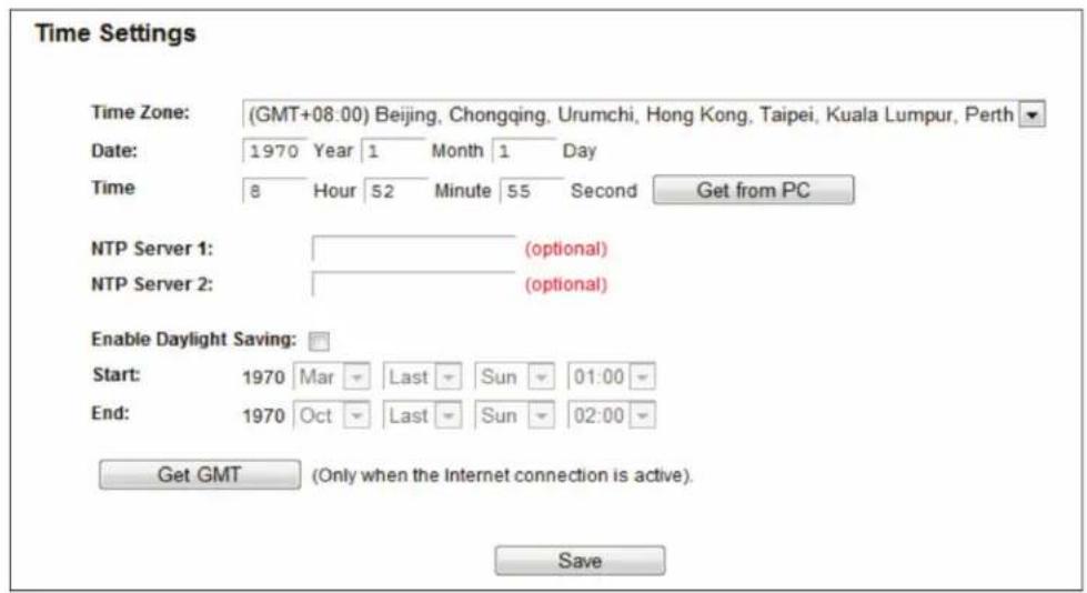
Figure 5-115. Time settings.
- Time Zone—Select your local time zone from this pull down list.
- Date—Enter your local date in MM/DD/YY into the right blanks.
- Time—Enter your local time in HH/MM/SS into the right blanks.
- Get From PC—Enter your PC's current time into the right blanks.
- NTP Server 1 / NTP Server 2—Enter the address or domain of the NTP Server 1 or NTP Server 2, and then the router will get the time from the NTP Server. In addition, the router has some built-in common NTP Servers, so it can get time automatically once it connects to the Internet.
- Enable Daylight Saving—Check the box to enable the Daylight Saving function.
- Start—The time to start the Daylight Saving. Select the month in the first field, the week in the second field, the day in the third field, and the time in the last field.
- End—The time to end the Daylight Saving. Select the month in the first field, the week in the second field, the day in the third field, and the time in the last field.
To set time manually:
- Select your local time zone.
- Enter the Date in Month/Day/Year format.
- Enter the Time in Hour/Minute/Second format.
- Click Save.
To set time automatically:
- Select your local time zone.
- Enter the address or domain of the NTP Server 1 or NTP Server 2.
- Click the Get GMT button to get system time from Internet if you are connected to the Internet.
To set Daylight Saving:
- Check the box to enable Daylight Saving.
- Select the start time from the drop-down lists in the Start field.
- Select the end time from the drop-down lists in the End field.
- Click the Save button to save the settings.
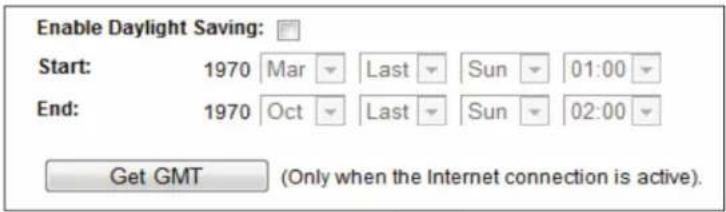
Figure 5-116. Time settings.
NOTES:
- This setting will be used for some time-based functions such as firewall. You must specify your time zone once you login to the router successfully; otherwise, these functions will not take effect.
- The time will be lost if the router is turned off.
- The router will automatically obtain GMT from the Internet if it is configured accordingly.
- The Daylight Saving will take effect one minute after the configurations are completed.
5.21.2 Diagnostic
Choose "System Tools —> Diagnostic," then you can use the Ping or Traceroute function to check connectivity of your network.
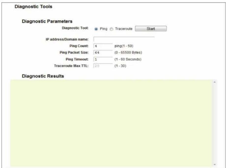
Figure 5-117. Diagnostic Tools.
- Diagnostic Tool—Check the radio button to select one diagnostic tool.
- Ping—This diagnostic tool troubleshoots connectivity, reachability, and name resolution to a given host or gateway.
- Traceroute—This diagnostic tool tests the performance of a connection.
NOTE: You can use ping/traceroute to test both numeric IP address and domain name. If pinging/tracerouting the IP address is successful, but pinging/tracerouting the domain name is not, you might have a name resolution problem. In this case, ensure that the domain name you are specifying can be resolved by using Domain Name System (DNS) queries.
- IP Address/Domain Name—Enter the IP Address or Domain Name of the PC you want to diagnose.
- Ping Count—Specifies the number of Echo Request messages sent. The default is 4.
- Ping Packet Size—Specifies the number of data bytes to be sent. The default is 64.
- Ping Timeout—Time to wait for a response, in milliseconds. The default is 800.
- Traceroute Max TTL—Set the maximum number of hops (max TTL to be reached) in the path to search for the target (destination). The default is 20.
Click Start to check the connectivity of the Internet.
The Diagnostic Results page displays the results.
If the result is similar to the following screen, the connectivity of the Internet is good.
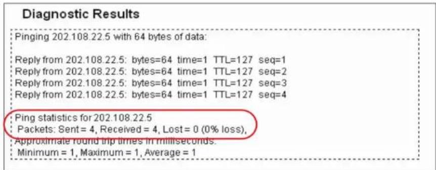
Figure 5-118. Diagnostic Results.
NOTES:
- Only one user can use the diagnostic tools at a time.
- "Ping Count," "Ping Packet Size," and "Ping Timeout" are Ping Parameters, and "Traceroute Max TTL" is a Traceroute Parameter.
5.21.3 Firmware Upgrade
Choose "System Tools —> Firmware Upgrade," then you can update the latest version of firmware for the router on the following screen.
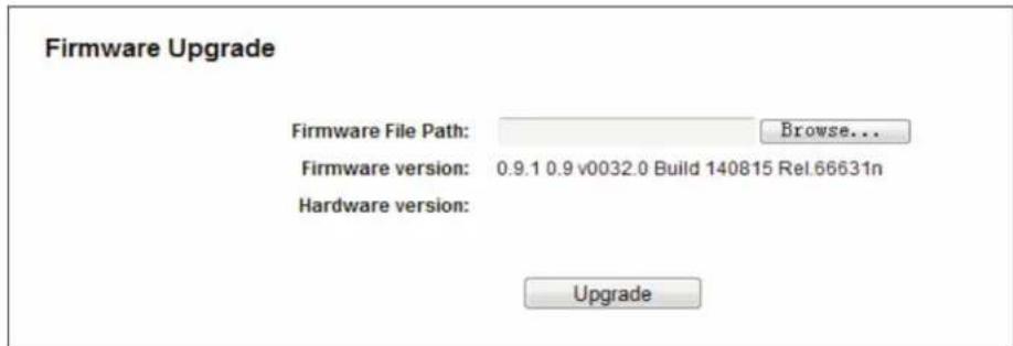
Figure 5-119. Firmware Upgrade.
- Firmware Version—Displays the current firmware version.
- Hardware Version—Displays the current hardware version. The hardware version of the upgrade file must be higher than the router's current hardware version.
To upgrade the router's firmware, follow these instructions:
- Enter or select the path name where you save the upgrade file on the computer into the Firmware File Path blank.
- Click the Upgrade button.
- The router will reboot while upgrading finishes.
NOTES:
- When you upgrade the router's firmware, you may lose its current configurations, so before upgrading the firmware, write down some of your customized settings to avoid losing important settings.
- Do not turn off the router or press the Reset button while the firmware is being upgraded. Loss of power during the upgrade could damage the router.
- The firmware version must correspond to the hardware.
- The upgrade process takes a few moments and the router restarts automatically when the upgrade is complete.
5.21.4 Factory Defaults
Choose "System Tools —> Factory Defaults," then you can restore the configurations of the router to factory defaults on the following screen.
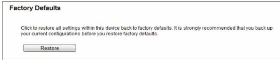
Figure 5-120. Restore Factory Default.
Click the Restore button to reset all configuration settings to their default values.
• The default User Name: admin
• The default Password: admin
• The default Subnet Mask: 255.255.255.0
NOTE: All changed settings will be lost when defaults are restored.
Choose "System Tools—> Backup & Restore," then you can save the current configuration of the router as a backup file and restore the configuration via a backup file.
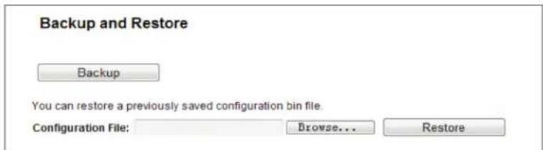
Figure 5-121. Backup & Restore Configuration.
- Click the Backup button to save all configuration settings as a backup file in your local computer.
- To upgrade the router's configuration, follow these instructions.
- Click the Browse button to find the configuration file that you want to restore.
- Click the Restore button to update the configuration with the file whose path is the one you input or selected in the blank.
NOTE: The current configuration will be replaced by the uploading configuration file. The wrong process will leave the device unmanaged. The restore process lasts for 20 seconds, and the router will restart automatically. Keep the power of the router on during the upload.
5.21.6 Reboot
Choose "System Tools —> Reboot," then you can click the Reboot button to reboot the router via the next screen.
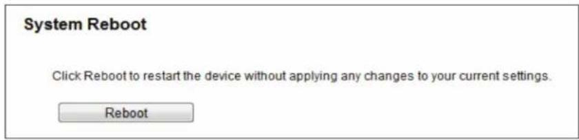
Figure 5-122. Reboot the router.
Some settings of the router will take effect only after rebooting, and include:
- Change the LAN IP Address (system will reboot automatically).
- Upgrade the firmware of the router (system will reboot automatically).
- Restore the router's settings to factory defaults (system will reboot automatically).
- Update the configuration with the file (system will reboot automatically).
5.21.7 Password
Choose "System Tools → Password," then you can change the factory default user name and password of the router in the next screen.
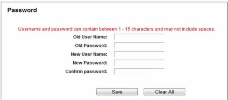
Figure 5-123. Password.
We strongly recommend that you change the factory default user name and password of the router, because all users who try to access the router's Web-based utility or Quick Setup will be prompted for the router's default user name and password.
NOTE: The new user name and password must not exceed 14 characters in length and not include any spaces. Enter the new Password twice to confirm it.
Click the Save button when finished.
Click the Clear All button to clear all.
5.21.8 System Log
Choose "System Tools —> System Log," then you can view the logs of the router.
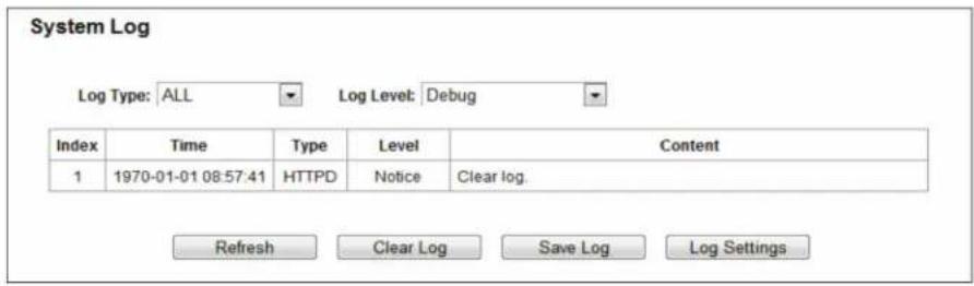
Figure 5-124. System Log screen.
- Log Type—By selecting the log type, only logs of this type will be shown.
- Log Level—By selecting the log level, only logs of this level will be shown.
- Refresh—Refresh the page to show the latest log list.
- Clear Log—All the logs will be deleted from the router permanently, not just from the page.
- Save Log—Click to save all the logs in a txt file.
- Log Settings—Click to change the log settings.
5.21.9 Statistics
Choose "System Tools Statistics," then you can view the statistics of the router, including total traffic and current traffic of the last Packets Statistic Interval.
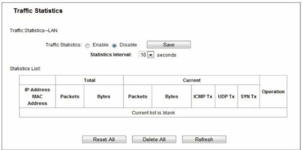
Figure 5-125. Statistics.
- Statistics Status—Enable or Disable. The default value is disabled. To enable it, click the Enable button. If it is disabled, the function of DoS protection in Security settings will be disabled.
- Statistics Interval (5-60)—The default value is 10. Select a value between 5 and 60 seconds in the drop-down list. The Packets Statistic interval indicates the time section of the packets statistic.
Click Reset All to reset the values of all the entries to zero.
Click Delete All to delete all entries in the table.
Click the Refresh button to refresh immediately.
Table 5-1. Statistics table.
| IP/MAC Address The IP and MAC address are displayed with related statistics. | ||
| Total | Packets | The total number of packets received and transmitted by the router. |
| Bytes The total | number of bytes received and transmitted by the router. | |
| Current | Packets | The total number of packets received and transmitted in the last Packets Statistic interval seconds. |
| Bytes The total | number of bytes received and transmitted in the last Packets Statistic interval seconds. | |
| ICMP Tx | The number of the ICMP packets transmitted to WAN per second at the specified Packets Statistics interval. It is shown as “current transmitting rate / Max transmitting rate.” | |
| UDP Tx The number of UDP packets transmitted to the WAN per second at the specified Packets Statistics interval. It is shown like “current transmitting rate / Max transmitting rate.” | ||
| TCP SYN Tx The number of TCP SYN packets transmitted to the WAN per second at the specified Packets Statistics interval. It is shown as “current transmitting rate / Max transmitting rate.” | ||
| Operation Reset Reset the value of he entry to zero. | ||
There are 5 entries on each page. Click Previous to return to the previous page and Next to go to the next page.
5.22 Logout
Choose "Logout," and you will be back to the login screen as shown in Figure 5-125.
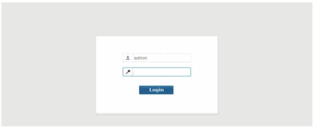
Figure 5-126. Login screen.
Appendix A. FAQ
- How do I configure the router to access the Internet via ADSL users?
1a. First, configure the ADSL Modem in the RFC1483 bridge model.
1b. Connect the Ethernet cable from your ADSL Modem to the WAN port on the router. The telephone cord plugs into the Line port of the ADSL Modem.
1c. Login to the router, click the "Network" menu on the left of your browser, and click the "WAN" submenu. On the WAN page, select "PPPoE" for the WAN Connection Type. Type the user name in the "Username" field and password in the "Password" field, type the password in the "Confirm Password" field again, and finish by clicking "Connect."
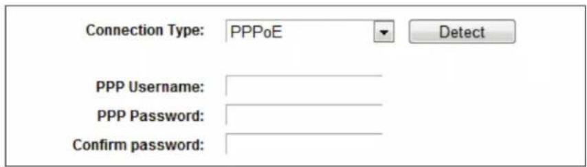
Figure A-1. PPPoE Connection Type.
1d. If your ADSL lease is in "pay-according-time" mode, select "Connect on demand" or "Connect manually" for Internet connection mode. Type an appropriate number for "Max Idle Time" to avoid wasting paid time. Otherwise, you can select "Always on" for Internet connection mode.
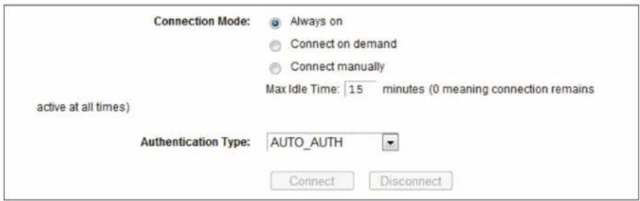
Figure A-2. PPPoE Connection Mode.
NOTES:
Sometimes the connection cannot be disconnected even though you specify a time for Max Idle Time, since some applications visit the Internet continually in the background.
If you are a Cable user, configure the router following the above steps.
- How do I configure the router to access the Internet via Ethernet users?
2a. Login to the router, click the "Network" menu on the left of your browser, and click the "WAN" submenu. On the WAN page, select "Dynamic IP" for "WAN Connection Type," then click "Save."
2b. Some ISPs require that you register the MAC Address of your adapter, which is connected to your cable/DSL Modem during installation. If your ISP requires MAC registration, login to the router and click the "Network" menu link on the left of your browser, then click "MAC Clone" submenu link. On the "MAC Clone" page, if your PC's MAC address is the proper MAC address, click the "Clone MAC Address" button and your PC's MAC address will fill in the "WAN MAC Address" field. Or, type the MAC Address into the "WAN MAC Address" field. The format for the MAC Address is XX:XX:XX:XX:XX:XX. Click the "Save" button. The setting will take effect after rebooting.
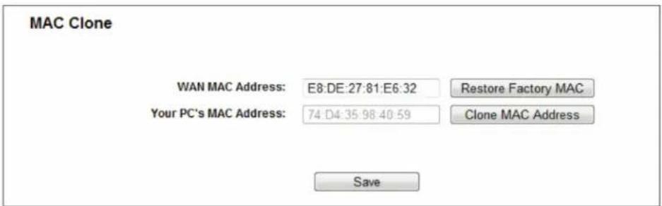
Figure A-3. MAC Clone.
- I want to use Netmeeting, what do I need to do?
3a. If you start Netmeeting as a host, you don't need to do anything with the router.
3b. If you start as a response, you need to configure Virtual Server or DMZ Host and make sure the H323 ALG is enabled.
3c. How to configure Virtual Server: Log in to the router, click the "Forwarding" menu on the left of your browser, and click the "Virtual Servers" submenu. On the "Virtual Servers" page, click Add New. Then on the "Add or Modify a Virtual Server Entry" page, enter "1720" for the "Service Port" blank, and your IP address for the "IP Address" blank, using 192.168.1.169 as an example; remember to Enable and Save.
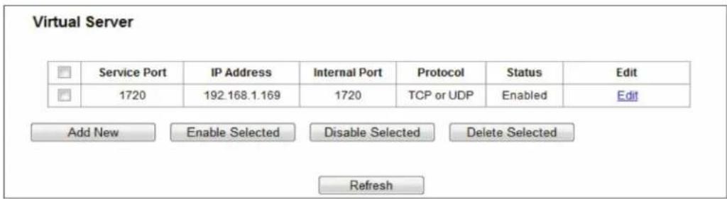
Figure A-4 Virtual Servers.
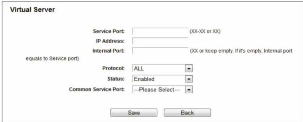
Figure A-5 Add or Modify a Virtual server Entry.
NOTE: The opposite side should call the WAN IP, which is displayed on the "Status" page.
- How to enable DMZ Host: Log in to the router, click the "Forwarding" menu on the left of your browser, and click "DMZ" submenu. On the "DMZ" page, click Enable radio button and type your IP address into the "DMZ Host IP Address" field, using 192.168.1.169 as an example; remember to click the Save button.
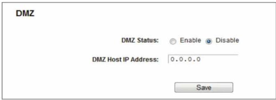
Figure A-6. DMZ.
- How to enable H323 ALG: Log in to the router, click the "Security" menu on the left of your browser, and click the "Basic Security" submenu. On the "Basic Security" page, check the Enable radio button next to H323 ALG. Remember to click the Save button.
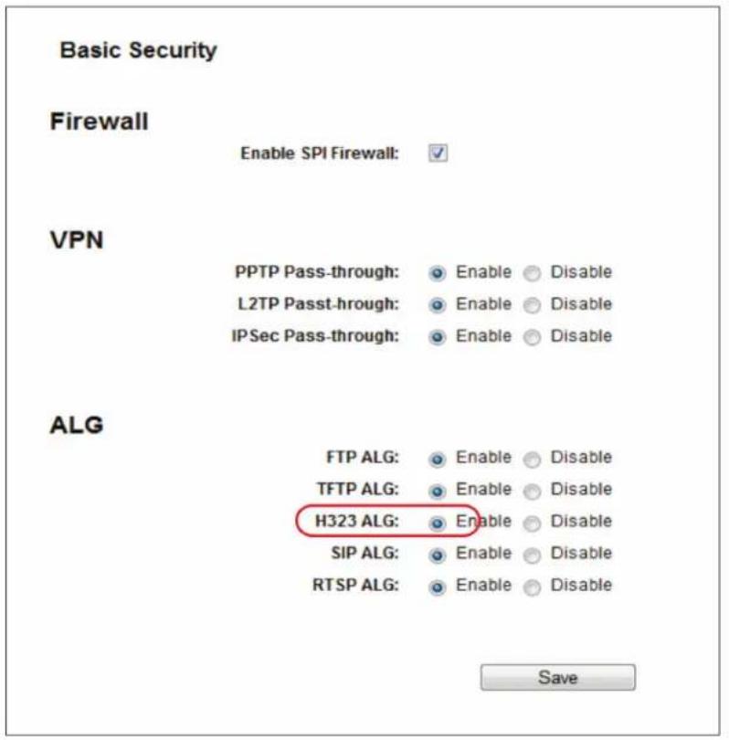
Figure A-7. Basic Security.
- The wireless stations cannot connect to the router.
6a. Make sure the "Wireless Radio Band" is enabled.
6b. Make sure that the wireless stations' SSID matches with the router's SSID.
6c. Make sure the wireless stations have the correct KEY for encryption when the router is encrypted.
6d. If the wireless connection is ready, but you can't access the router, check the IP Address of your wireless stations.
Appendix B: Configuring the PC
In this section, we'll introduce how to install and configure the TCP/IP correctly in Windows XP. First make sure your Ethernet Adapter is working, then refer to the adapter's manual if needed.
Follow these steps to install the TCP/IP component.
- On the Windows taskbar, click the Start button, point to Settings, and then click Control Panel.
- Click the Network and Internet Connections icon, and then click on the Network Connections tab in the appearing window.
- Right click the icon that showed below, select Properties on the prompt page.
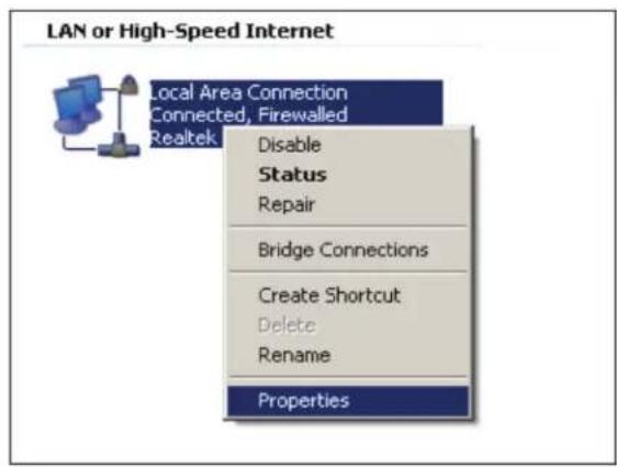
Figure B-1. Properties option.
- In the prompt page shown below, double click on the Internet Protocol (TCP/IP).
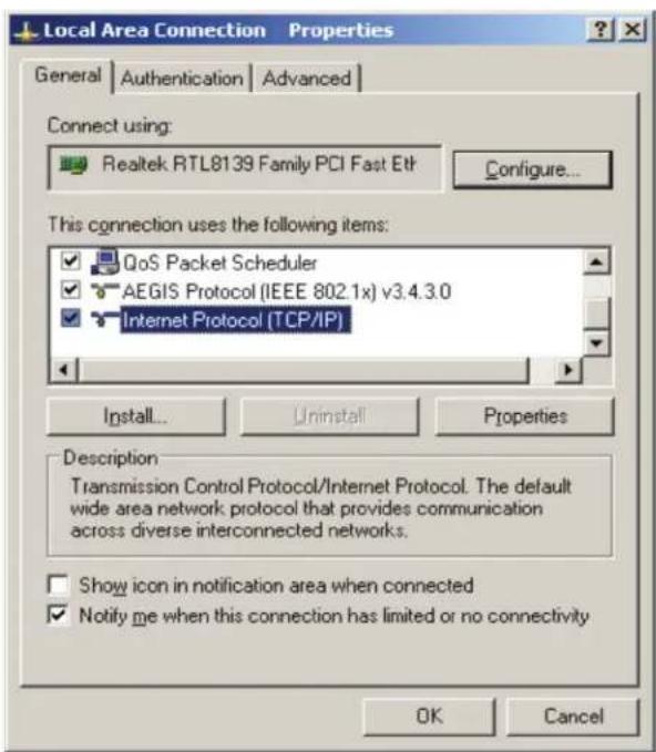
Figure B-2. Select TCP/IP.
- The following TCP/IP Properties window will display and the IP Address tab is open on this window by default.
- Select Obtain an IP address automatically and Obtain DNS server automatically, as shown in the next Figure.
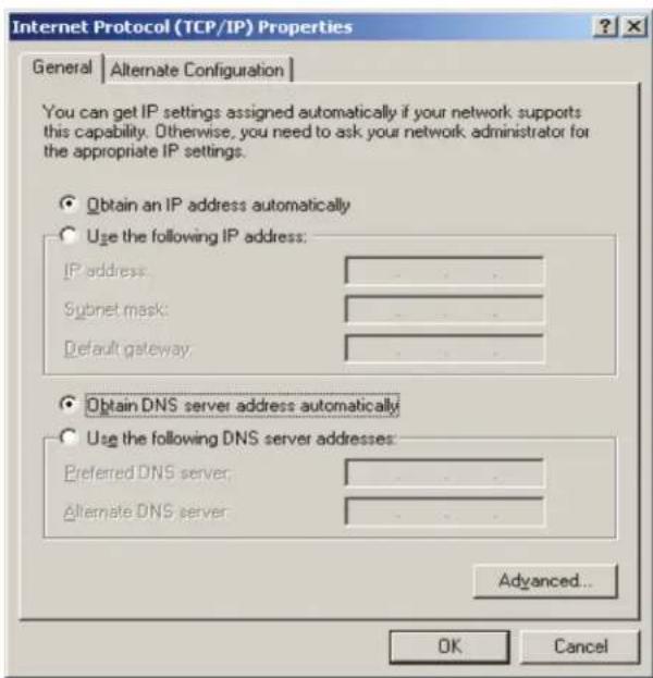
Figure B-3. Obtain IP address automatically.
Appendix C. Glossary
802.11ac - IEEE 802.11ac is a wireless computer networking standard of 802.11. This specification will enable multi-station WLAN throughput of at least 1 gigabit per second. This is accomplished by extending the air interface concepts embraced by 802.11n: wider RF bandwidth, more MIMO spatial streams, multi-user MIMO, and high-density modulation (up to 256 QAM).
802.11n - 802.11n builds upon previous 802.11 standards by adding MIMO (multiple-input multiple-output). MIMO uses multiple transmitter and receiver antennas to allow for increased data throughput via spatial multiplexing and increased range by exploiting the spatial diversity, perhaps through coding schemes like Alamouti coding. The Enhanced Wireless Consortium (EWC) [3] was formed to help accelerate the IEEE 802.11n development process and promote a technology specification for interoperability of next-generation wireless local area networking (WLAN) products.
802.11b - The 802.11b standard specifies a wireless networking at 11 Mbps using direct-sequence spread-spectrum (DSSS) technology and operating in the unlicensed radio spectrum at 2.4 GHz, and WEP encryption for security. 802.11b networks are also referred to as Wi-Fi networks.
802.11g - specification for wireless networking at 54 Mbps using direct-sequence spread-spectrum (DSSS) technology, using OFDM modulation and operating in the unlicensed radio spectrum at 2.4GHz, and backward compatibility with IEEE 802.11b devices, and WEP encryption for security.
DDNS (Dynamic Domain Name System) - The capability of assigning a fixed host and domain name to a dynamic Internet IP Address.
DHCP (Dynamic Host Configuration Protocol) - A protocol that automatically configure the TCP/IP parameters for the all the PC(s) that are connected to a DHCP server.
DMZ (Demilitarized Zone) - A Demilitarized Zone allows one local host to be exposed to the Internet for a special-purpose service such as Internet gaming or videoconferencing.
DNS (Domain Name System) - An Internet Service that translates the names of websites into IP addresses.
Domain Name - A descriptive name for an address or group of addresses on the Internet.
DSL (Digital Subscriber Line) - A technology that allows data to be sent or received over existing traditional phone lines.
ISP (Internet Service Provider) - A company that provides access to the Internet.
MTU (Maximum Transmission Unit) - The size in bytes of the largest packet that can be transmitted.
NAT (Network Address Translation) - NAT technology translates IP addresses of a local area network to a different IP address for the Internet.
PPPoE (Point to Point Protocol over Ethernet) - PPPoE is a protocol for connecting remote hosts to the Internet over an always-on connection by simulating a dial-up connection.
SSID - A Service Set Identification is a thirty-two character (maximum) alphanumeric key identifying a wireless local area network. For the wireless devices in a network to communicate with each other, all devices must be configured with the same SSID. This is typically the configuration parameter for a wireless PC card. It corresponds to the ESSID in the wireless Access Point and to the wireless network name.
WEP (Wired Equivalent Privacy) - A data privacy mechanism based on a 64-bit or 128-bit or 152-bit shared key algorithm, as described in the IEEE 802.11 standard.
Wi-Fi - A trade name for the 802.11b wireless networking standard, given by the Wireless Ethernet Compatibility Alliance (WECA, see http://www.wi-fi.net), an industry standards group promoting interoperability among 802.11b devices.
WLAN (Wireless Local Area Network) - A group of computers and associated devices communicate with each other wirelessly, which network serving users are limited in a local area.
Black Box Tech Support: FREE! Live. 24/7.
Tech support the way it should be.

natural_image
Close-up portrait of a smiling man with short hair holding a small object, against a blue gradient background (no text or symbols visible)Great tech support is just 60 seconds away at 877-877-2269 or blackbox.com.

BLACK BOX®
About Black Box
Black Box provides an extensive range of networking and infrastructure products. You'll find everything from cabinets and racks and power and surge protection products to media converters and Ethernet switches all supported by free, live 24/7 Tech support available in 60 seconds or less.
© Copyright 2016. Black Box Corporation. All rights reserved. Black Box ^® and the Double Diamond logo are registered trademarks of BB Technologies, Inc. Any third-party trademarks appearing in this manual are acknowledged to be the property of their respective owners.
WRT750A_user_rev1

- User Manual
- Trademarks Used in this Manual
- Federal Communications Commission and Industry Canada Radio Frequency Interference Statements
- FCC RF Radiation Exposure Statement
- CE Mark Warning
- Disclaimer:
- National Restrictions
- Table of Contents
- Overview
- Introduction
- Features
- What's Included
- Hardware Description
- Front Panel
- NOTES:
- Back Panel
- Installing the Router
- System Requirements
- Installation Environment Requirements
- Connecting the Router
- Quick Installation Guide
- TCP/IP Configuration
- Quick Installation Steps
- Quick Setup - MAC Clone
- Quick Setup - Static IP
- 4-17. Quick Setup—Wireless 2.4 GHz.
- Chapter 5. Configuring the Router
- Login
- Status
- Quick Setup
- Network
- WAN
- LAN
- MAC Clone
- Dual Band Selection
- Wireless 2.4 GHz
- Basic Settings
- WPS
- Wireless Security
- Wireless MAC Filtering
- Wireless Advanced
- Wireless Statistics
- Wireless 5 GHz
- Basic Settings
- WPS
- Wireless Security
- Wireless MAC Filtering
- Wireless Advanced
- Wireless Statistics
- Guest Network
- DHCP
- DHCP Settings
- DHCP Clients List
- Address Reservation
- USB Settings
- USB Mass Storage
- User Accounts
- Storage Sharing
- Folder Browse
- FTP Server
- Media Server
- NAT
- Forwarding
- Virtual Servers
- Port Triggering
- DMZ
- UPnP
- Security
- Basic Security
- Advanced Security
- Local Management
- Remote Management
- Parent Control
- Access Control
- Rule
- How to add a new rule:
- Host
- Target
- Schedule
- Advanced Routing
- Static Route List
- System Routing Table
- Bandwidth Control
- Binding Settings
- ARP List
- Dynamic DNS
- No -ip.com DDNS
- Comexe.cn DDNS
- Dyndns.com DDNS
- IPv6
- IPv6 Status
- IPv6 WAN
- IPv6 LAN
- System Tools
- Time Settings
- To set time manually:
- To set time automatically:
- To set Daylight Saving:
- Diagnostic
- Firmware Upgrade
- Factory Defaults
- Reboot
- Password
- System Log
- Statistics
- Logout
- Appendix A. FAQ
- Appendix B: Configuring the PC
- Appendix C. Glossary
- Black Box Tech Support: FREE! Live. 24/7.
- BLACK BOX®
- About Black Box
Brand : Black Box
Model : WRT750A
Category : Router