
DLA-VS4010 - Video projector JVC - Free user manual and instructions
Find the device manual for free DLA-VS4010 JVC in PDF.


| Product Type | D-ILA Video Projector |
| Resolution | 4K UHD (4096 x 2160) |
| Brightness | 2000 Lumens |
| Contrast Ratio | 100,000:1 (Dynamic) |
| Light Source | UHP Lamp, 265W |
| Lamp Life | 4500 Hours (Normal Mode) |
| Dimensions (W x H x D) | 500 x 200 x 505 mm |
| Weight | 15.6 kg |
| Power Consumption | 380W (Typical), 0.5W Standby |
| Power Supply | AC 100-240V, 50/60Hz |
| Inputs | 2 x HDMI 2.0, 2 x USB, RJ-45, RS-232C |
| Lens Shift | Vertical ±80%, Horizontal ±34% (Motorized) |
| Zoom | 1.6x Motorized Zoom/Focus |
| Keystone Correction | Vertical ±30° |
| Supported HDR | HDR10, HLG |
| 3D Support | Yes (DLP Link) |
| Noise Level | 23 dB (Eco Mode) |
| Maintenance | Air filter cleaning every 500 hours; lamp replacement |
| Safety | Laser class 1 (lamp based, no laser) |
| Spare Parts | Replacement lamp (PK-L2615U), air filter |
| General Information | Ceiling mountable, 2-year warranty |
Frequently Asked Questions - DLA-VS4010 JVC
User questions about DLA-VS4010 JVC
0 question about this device. Answer the ones you know or ask your own.
Ask a new question about this device
Download the instructions for your Video projector in PDF format for free! Find your manual DLA-VS4010 - JVC and take your electronic device back in hand. On this page are published all the documents necessary for the use of your device. DLA-VS4010 by JVC.
USER MANUAL DLA-VS4010 JVC
natural_image
Technical line drawing of a rectangular electronic device with internal components and mounting brackets (no text or symbols)D-ILA® BLU-Escent
Thank you for purchasing this JVC product.
Please study this instruction manual carefully before starting to operate the unit, in order to use the unit correctly.
We take no responsibility for any problems resulting from misuse of this unit by operating this equipment other than instructed in this manual.
For Customer use :
Enter below the model No. and the serial No. which are located on the back of the cabinet. Retain this information for future reference.
Model No.
Serial No.
Safety Precautions
IMPORTANT INFORMATION
WARNING:
TO PREVENT FIRE OR SHOCK HAZARDS, DO NOT EXPOSE THIS APPLIANCE TO RAIN OR MOISTURE.
WARNING:
THIS APPARATUS MUST BE EARTHED.
CAUTION:
To reduce the risk of electric shock, do not remove cover. Refer servicing to qualified service personnel.
This projector is equipped with a 3-blade grounding type plug to satisfy FCC rule. If you are unable to insert the plug into the outlet, contact your electrician.
FCC INFORMATION (U.S.A. only)
CAUTION:
Changes or modification not approved by JVC could void the user's authority to operate the equipment.
NOTE:
This equipment has been tested and found to comply with the limits for a Class A digital device, pursuant to Part 15 of the FCC Rules. These limits are designed to provide reasonable protection against harmful interference when the equipment is operated in a commercial environment. This equipment generates, uses, and can radiate radio frequency energy and, if not installed and used in accordance with the instruction manual, may cause harmful interference to radio communications.
Operation of this equipment in a residential area is likely to cause harmful interference in which case the user will be required to correct the interference at his own expense.
MACHINE NOISE INFORMATION (Germany only)
Changes Machine Noise Information Ordinance 3. GSGV, January 18, 1991: The sound pressure level at the operator position is equal or less than 70 dB (A) according to ISO 7779.
About the installation place
Do not install the projector in a place that cannot support its weight securely.
If the installation place is not sturdy enough, the projector could fall or overturn, possibly causing personal injury.
IMPORTANT SAFEGUARDS
Electrical energy can perform many useful functions. This unit has been engineered and manufactured to assure your personal safety. But IMPROPER USE CAN RESULT IN POTENTIAL ELECTRICAL SHOCK OR FIRE HAZARD. In order not to defeat the safeguards incorporated into this product, observe the following basic rules for its installation, use and service. Please read these Important Safeguards carefully before use.
- All the safety and operating instructions should be read before the product is operated.
- The safety and operating instructions should be retained for future reference.
- All warnings on the product and in the operating instructions should be adhered to.
- All operating instructions should be followed.
- Place the projector near a wall outlet where the plug can be easily unplugged.
- Unplug this product from the wall outlet before cleaning.
- Do not use liquid cleaners or aerosol cleaners. Use a damp cloth for cleaning.
- Do not use attachments not recommended by the product manufacturer as they may be hazardous.
- Do not use this product near water. Do not use immediately after moving from a low temperature to high temperature, as this causes condensation, which may result in fire, electric shock, or other hazards.
- Do not place this product on an unstable cart, stand, or table. The product may fall, causing serious injury to a child or adult, and serious damage to the product. The product should be mounted according to the manufacturer's instructions, and should use a mount recommended by the manufacturer.
- When the product is used on a cart, care should be taken to avoid quick stops, excessive force, and uneven surfaces which may cause the product and cart to overturn, damaging equipment or causing possible injury to the operator.
PORTABLE CART WARNING (symbol provided by RETAC)

S3126A
- Slots and openings in the cabinet are provided for ventilation. These ensure reliable operation of the product and protect it from overheating. These openings must not be blocked or covered. (The openings should never be blocked by placing the product on bed, sofa, rug, or similar surface. It should not be placed in a built-in installation such as a bookcase or rack unless proper ventilation is provided and the manufacturer's instructions have been adhered to.) For proper ventilation, separate the product from other equipment, which may prevent ventilation and keep a distance.
- This product should be operated only with the type of power source indicated on the label. If you are not sure of the type of power supply to your home, consult your product dealer or local power company.
- This product is equipped with a three-wire plug. This plug will fit only into a grounded power outlet. If you are unable to insert the plug into the outlet, contact your electrician to install the proper outlet. Do not defeat the safety purpose of the grounded plug.
- The lens for this product is optional. Do not attach the power cord when the lens is not attached. Turning on the power when no lens is attached may result in fire, electric shock, or other hazards.
- Power-supply cords should be routed so that they are not likely to be walked on or pinched by items placed upon or against them. Pay particular attention to cords at doors, plugs, receptacles, and the point where they exit from the product.
- For added protection of this product during a lightning storm, or when it is left unattended and unused for long periods of time, unplug it from the wall outlet and disconnect the cable system. This will prevent damage to the product due to lightning and power line surges.
- Do not overload wall outlets, extension cords, or convenience receptacles on other equipment as this can result in a risk of fire or electric shock.
- Never push objects of any kind into this product through openings as they may touch dangerous voltage points or short out parts that could result in a fire or electric shock. Never spill liquid of any kind on the product.
- Do not attempt to service this product yourself as opening or removing covers may expose you to dangerous voltages and other hazards. Refer all service to qualified service personnel.
- Unplug this product from the wall outlet and refer service to qualified service personnel under the following conditions:
a) When the power supply cord or plug is damaged.
b) If liquid has been spilled, or objects have fallen on the product.
c) If the product has been exposed to rain or water.
d) If the product does not operate normally by following the operating instructions. Adjust only those controls that are covered by the Operation Manual, as an improper adjustment of controls may result in damage and will often require extensive work by a qualified technician to restore the product to normal operation.
e) If the product has been dropped or damaged in any way.
f) When the product exhibits a distinct change in performance, this indicates a need for service.
- When replacement parts are required, be sure the service technician has used replacement parts specified by the manufacturer or with same characteristics as the original part. Unauthorized substitutions may result in fire, electric shock, or other hazards.
- Upon completion of any service or repairs to this product, ask the service technician to perform safety checks to determine that the product is in proper operating condition.
- The product should be placed more than one foot away from heat sources such as radiators, heat registers, stoves, and other products (including amplifiers) that produce heat.
- When connecting other products such as VCR's, and DVD players, you should turn off the power of this product for protection against electric shock.
- Do not place combustibles behind the cooling fan. For example, cloth, paper, matches, aerosol cans or gas lighters that present special hazards when over heated.
- Do not look into the projection lens while the illumination lamp is turned on. Exposure of your eyes to the strong light can result in impaired eyesight.
- Do not look into the inside of this unit through vents ventilation holes), etc. Do not look at the illumination lamp directly by opening the cabinet while the illumination lamp is turned on. The illumination lamp also contains ultraviolet rays and the light is so powerful that your eyesight can be impaired.
- Do not drop, hit, or damage the light-source lamp lamp unit) in any way. It may cause the light-source lamp to break and lead to injuries. Do not use a damaged light source lamp. If the light-source lamp is broken, ask your dealer to repair it. Fragments from a broken light-source lamp may cause injuries.
- The light-source lamp used in this projector is a high pressure lamp. Be careful when disposing of the lightsource lamp. If anything is unclear, please consult your dealer.
- Do not ceiling-mount the projector to a place which tends to vibrate; otherwise, the attaching fixture of the projector could be broken by the vibration, possibly causing it to fall or overturn, which could lead to personal injury.
- Use only the accessory cord designed for this product to prevent shock.
\* DO NOT allow any unqualified person to install the unit.
Be sure to ask your dealer to install the unit (e.g. attaching it to the ceiling) since special technical knowledge and skills are required for installation. If installation is performed by an unqualified person, it may cause personal injury or electrical shock.
POWER CONNECTION
For USA and Canada only Use only the following power cord.
Power cord
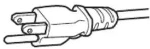
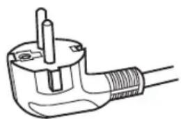
The power supply voltage rating of this product is AC100V – AC240V. Use only the power cord designated by our dealer to ensure Safety and EMC. Ensure that the power cable used for the projector is the correct type for the AC outlet in your country. Consult your product dealer.
Power cord
natural_image
Line drawing of a U-shaped electrical plug with a screw and terminal pin (no text or symbols)For European continent countries
WARNING:
Do not cut off the main plug from this equipment.
If the plug fitted is not suitable for the power points in your home or the cable is too short to reach a power point, then obtain an appropriate safety approved extension lead or adapter or consult your dealer. If nonetheless the mains plug is cut off, dispose of the plug immediately, to avoid a possible shock hazard by inadvertent connection to the main supply. If a new main plug has to be fitted, then follow the instruction given below.
WARNING:
THIS APPARATUS MUST BE EARTHED.
IMPORTANT (Europe only):
The wires in the mains lead on this product are colored in accordance with the following cord:
Green-and-yellow : Earth
Blue : Neutral
Brown : Live
As these colors may not correspond with the colored making identifying the terminals in your plug, proceed as follows:
The wire which is colored green-and-yellow must be connected to the terminal which is marked M with the letter E or the safety earth or colored green or green-and-yellow. The wire which is colored blue must be connected to the terminal which is marked with the letter N or colored black.
The wire which is colored brown must be connected to the terminal which is marked with the letter L or colored red.
EMC Supplement
- This equipment is in conformity with the provisions and protection requirements of the corresponding European Directives. This equipment is designed for professional rejector appliances and can be used in the following environments.
- Controlled EMC environment (for example purpose built broadcasting or recording studio), and the rural outdoors environment (far away from railways, transmitters, overhead power lines, etc).
In order to keep the best performance and furthermore for electromagnetic compatibility we recommend to use the cables not exceeding the following length:
| Cables | Length | |
| Power cord | Power supply cord | 3.3 m |
| DVI (X4) Cable | Shielded cable | 5.0 m |
| USB Cable | Shielded cable | 2.0 m |
| LAN Cable | Shielded cable | 2.0 m |
| RS-232C Cable | Shielded cable | 1.6 m |
- The inrush current of this apparatus is 11.945 amperes.
WARNING:
This equipment is compliant with Class A of CISPR 32. In residential environment this equipment may cause radio interference.
Dear Customer,
This apparatus is in conformance with the valid European directives and standards regarding electromagnetic compatibility and electrical safety. European representative of JVC KENWOOD Corporation is: JVCKENWOOD Deutschland GmbH Konrad-Adenauer-Allee 1-11, 61118 Bad Vilbel, GERMANY
For the customers In the U.S.A. and Canada
CAUTION
Use of controls or adjustments or performance of procedures other than those specified herein may result in hazardous radiation exposure.
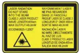
This Projector is classified as a CLASS 2 LASER PRODUCT.
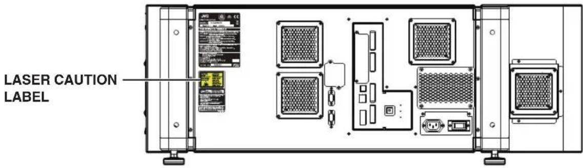
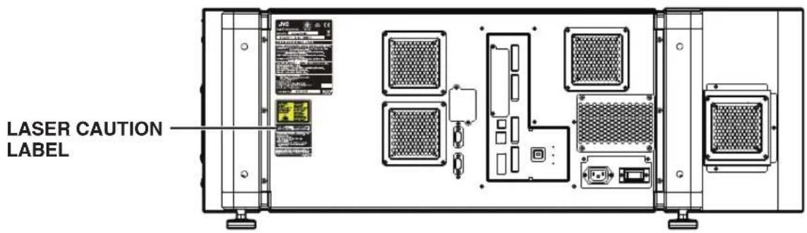
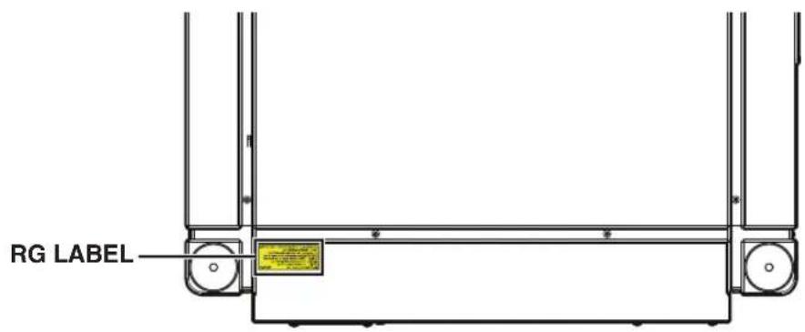
This CLASS 2 LASER PRODUCT label and Caution label is located on the Rear Side surface of the projector.
Location information of the labels
WARNING
LASER RADIATION
DO NOT STARE INTO THE BEAM
CLASS 2 LASER PRODUCT
CAUTION
Do not look into the lens while in use.
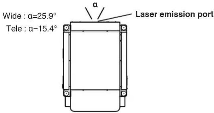
Light source specifications
30 W Laser diodes ×12
Wavelength 450 - 460 nm
Maximum output is 49.2 W
Beam divergence angle from lens of this unit
For the customers In other countries
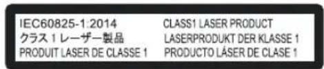
CLASS 1 LASER PRODUCT
LASER CAUTION LABEL
WARNING
Do not look into the lens while in use.
CAUTION
Use of controls or adjustments or performance of procedures other than those specified herein may result in hazardous radiation exposure.
Location information of the labels
IEC62471-5
RG LABEL
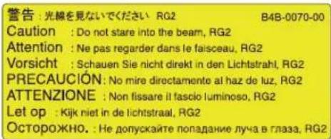
As with any bright light source, do not stare into the beam, RG2 IEC 62471-5:2015
ENGLISH
Information for Users on Disposal of Old Equipment and Batteries

Products
Battery
[European Union only]
These symbols indicate that equipment with these symbols should not be disposed of as general household waste. If you want to dispose of the product or battery, please consider the collection systems or facilities for appropriate recycling.
Notice: The sign Pb below the symbol for batteries indicates that this battery contains lead.
FRANÇAIS
Safety Precautions 2
Names and Functions of Parts 9
Front/Right, Left and Rear Side 9
Right Side 10
Connection and Installation
Installation 11
Optional Projection Lens 11
Minimum Space Required 11
Projector Installation Angle 12
Installing the Projector and Screen 13
Screen Size and Projection Distance 16
Connecting Video Signals of the Computer ..... 18
Connection During Single-Screen Mode Display 18
Connection During Two-Screen/Four-Screen Mode
Display 20
Network Settings
Connection Using a LAN Cable 22
Connection Example 22
Specifications of PC for Controlling this Projector 23
Turning On the Main Power 24
IP Address Settings 25
Assigning a static IP address 25
Assigning IP Address from the DHCP Server .... 28
Using the Mail Delivery Feature 28
Connection Example (When DHCP Server is Used) 28
Operation and Settings
Projecting Image 29
Useful Features During Projection 32
Displaying the Menu 33
User Settings Menu .... 34
User Settings Menu Structure .... 34
(1) Main Menu 35
(2) Image Menu 37
(3) Setting Menu 38
(4) Convergence Menu 39
(5) Lens Menu 40
(6) Option Menu 41
Administrator Settings Menu 42
Administrator Settings Menu Structure 42
(7) Admin.Network Menu 43
(8) Admin.E-mail Menu 45
(9) Admin.Option Menu 47
(10) Admin.Signal Menu 48
Others
Troubleshooting 50
What to do when these messages are displayed .. 52
Warnings Using Indicators 53
Warning Status 54
RS-232C Interface 55
Communication Specifications 55
Command Format 55
Maintenance 57
Cleaning and Replacing the Filter 57
Routine Servicing 59
Specifications 60
Dimensional Outline Drawing 63
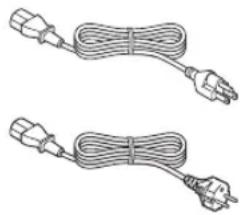
Accessories
Power cord (for USA) (about. 3.3 m) .... 1 piece
Power cord (for EU) (about. 3.3 m) .... 1 piece
Plug Holder 1 piece
natural_image
Two identical cable-winding electrical connectors with terminal plugs (no text or symbols)- Other items include the instruction manual, warranty, and other printed materials.
Content of this manual
- Personal computers or computers are expressed as computers or PCs in this manual.
- Contents of this manual are the copyright of JVC. All rights reserved. Unauthorized reproduction and duplication of this manual, in whole or in part, without the permission of JVC is strictly prohibited.
- The names of other companies' products that appear in this manual are the trademark or registered trademark of the respective companies. Symbols such as ^TM , ^® , and © are omitted in this manual.
- Designs, specifications, and other details described in this manual may be modified for improvement without prior notice.
Names and Functions of Parts
Front/Right, Left and Rear Side
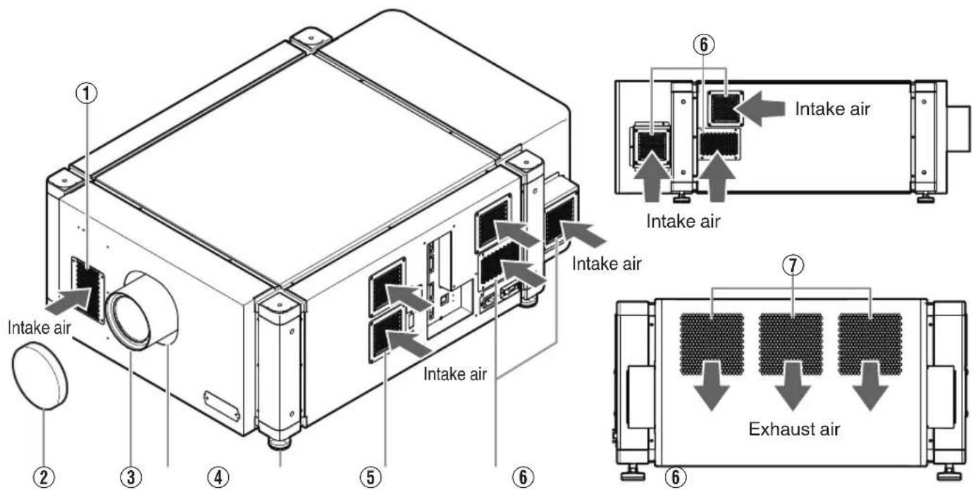
① Air Inlet/Filter
The air inlets absorb air to cool the interior of the projector. A filter is mounted inside the projector to remove dirt in the air that enters through the inlets. Clean the filter regularly. (P. 57)
- Do not block the air inlets with papers, cloth, or soft cushions. Doing so may cause heat to trap inside the projector and result in fire or malfunction.
② Lens Cap (included with the optional lens)
Fit the cap on the lens when this projector is not in use to prevent the lens from becoming dirty.
- Do not project images with the lens cap attached. The lens cap may be deformed due to the heat, or the projector may malfunction.
③ Projection Lens (optional)
Zoom lens or short focal length lens is optional. (P. 60)
Remove the lens cap before projection.
④ Lens Mounting Bracket
Mount the optional projection lens.
⑤ Adjustable Feet (x4)
Adjust the feet until the projector is level. The adjustable range is 20 mm for each. (P. 12)
⑥ Air Inlet/Filter
(Right Side: x5, Left Side: x3)
The air inlets absorb air to cool the interior of the projector. A filter is mounted inside the projector to remove dirt in the air that enters through the inlets. Clean the filter regularly. (P. 57)
⑦ Vent Hole
Warm air exits from the hole after cooling the projector.
- Do not block the vent holes with papers, cloth, or soft cushions. Doing so may cause heat to trap inside the projector and result in fire or malfunction.
Right Side
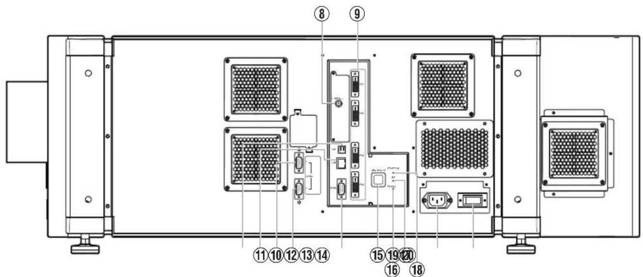
⑧ [e-shift Sync] Terminal (DLA-VS4810 only)
This is the input terminal for e-shift sync signals.
⑨ [DVI 1 to 4] Terminal
This is an input terminal for video signals. Connect it to the video output terminal of the computer. (P. 19, 21)
⑩ [USB] Terminal
Enables control of this projector by connecting it to a computer.
⑪ [LAN] Terminal
Enables control of this projector using a computer that is connected to the network.
⑫ [RS-232C 1] Terminal
⑬ [RS-232C 2] Terminal
⑭ [RS-232C] Terminal
This is the RS-232C interface-specific terminal. This projector can be controlled by connecting it to a computer using a RS-232C cable.
⑮ [OPERATE I/⏻] Button
Pressing this button for one second or longer when in the standby mode (main power supply is ON) turns on the power of the projector unit. Pressing it for one second or longer when the power is ON switches the projector to the standby mode.
⑯ [WARNING] Indicator
This indicator lights up in red when abnormality occurs on this projector.
- For details, refer to "Warnings Using Indicators" P. 53.
⑰ [LAMP] Indicator
This indicator lights up in yellow when the lifetime of the LD block exceeds 19,000 hours.
- For details, refer to "Warnings Using Indicators"P. 53.
- A message on the LD block lifespan appears when the lifetime of the LD block has exceeded 20,000 hours. (P. 52)
⑱ [STANDBY/ON] Indicator
Lit (Red) : When in the standby mode.
Lit (Green): When power is supplied.
Blinking (Red) : When cooling down (cool down mode). (P. 31)
Blinking (Green): When the projected image is temporarily hidden. (P. 32)
- For details, refer to "Warnings Using Indicators" P. 53.
⑲ AC Power Input Terminal
Connect the supplied cord to this terminal.
⑳ Main Power Supply Switch
Use this to turn ON/OFF the main power supply of the projector unit.
MEMO
- A stand-BY condition is indicated by the symbol ⏻.
• Power ON condition is indicated by the symbol I.
• Power OFF condition is indicated by the symbol O.
Installation
Please read the following carefully when installing this unit.
Optional Projection Lens
Mount the optional projection lens (P. 60). For details on mounting the lens, please consult your authorized dealer.
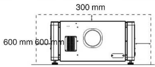
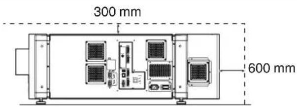
Minimum Space Required
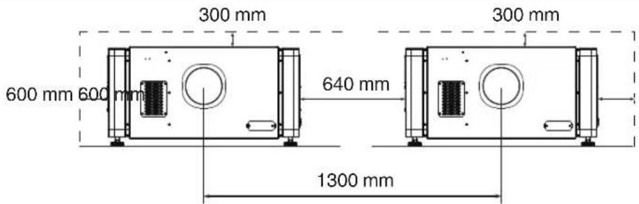
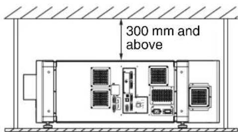
Do not use a cover that may enclose this unit or block the air inlets/vent holes. Allow sufficient space around this unit. When this unit is enclosed in a space with dimensions as indicated below, ventilate accordingly so that the internal and external temperatures are the same.
When using one set of projector
When using two sets of projectors side by side
When the projector is suspended

MEMO
• To prevent the projector from falling or toppling, it is recommended that the holder be fastened to the unit using bolts.
- To mount the projector to the ceiling, mount a special shelf to the ceiling, followed by installing the unit on the shelf. For safety and maintenance purposes, equipment that eases adjustment to a suitable height for maintenance is required.

CAUTION
- Special expertise and techniques are required for mounting this unit. Be sure to ask your dealer or a specialist to perform mounting.
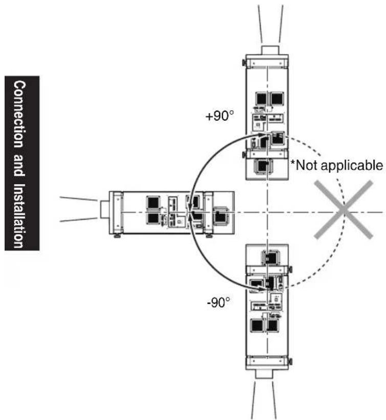
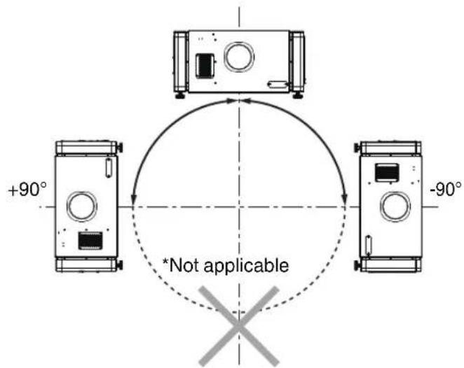
Projector Installation Angle
You can install this projector between ±90 both vertically and horizontally.
Vertical Angle
Horizontal Angle

CAUTION
- Special expertise and techniques are required for mounting this unit. Be sure to ask your dealer or a specialist to perform mounting.
- The projector cannot be installed upside down.
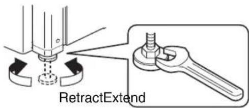
Adjusting the Inclination
Adjust the horizontal angle of the projector.
Lift the projector and turn the nut of the adjustable foot with a spanner in the direction indicated by the arrow to extend or retract the foot. The adjustable range is 20 mm.
Installing the Projector and Screen
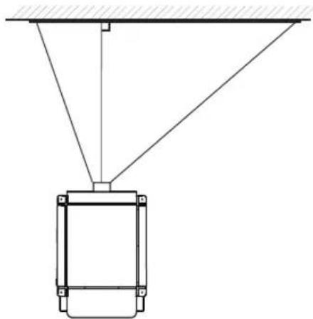
It is recommended that this projector be installed at right angle to the screen.
When a zoom lens (optional) is in use, you can make use of the lens shift feature of this projector to shift the projection screen vertically between 0% to ±50%, and horizontally between 0% to ±25%.
When a short focal length lens (optional) is in use, you can shift the projection screen position vertically between 0% to ±15%, and horizontally between 0% to ±5%.
Below are some examples on the layout when a zoom lens is used.
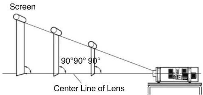
When shift amount in the upward direction is +50 %
Install the projector such that the lower end of the projection screen is at the same height as the center of the lens.
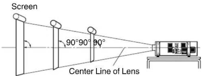
When shift amount in the upward/downward direction is 0 %
Install the projector such that the center of the projection screen is at the same height as the center of the lens.
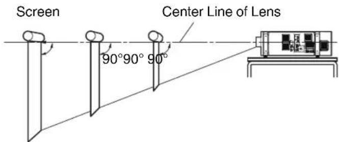
When shift amount in the downward direction is -50 %
Install the projector such that the upper end of the projection screen is at the same height as the center of the lens.
When shift amount in the right direction is +25 %
Install the projector such that the center of the lens is aligned with the 1/4 position from the left edge of the screen.
natural_image
Pure technical diagram of a suspended platform or support structure without any text, numbers, or symbolsWhen shift amount in the left/right direction is 0 %
Install the projector such that the center of the lens is aligned with the center of the screen.
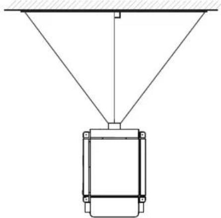
natural_image
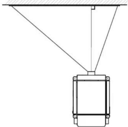
Pure technical diagram of a suspended mechanical component with diagonal lines and mounting base (no text or symbols)When shift amount in the left direction is -25 %
Install the projector such that the center of the lens is aligned with the 1/4 position from the right edge of the screen.
natural_image
Pure technical diagram of a suspended mechanical component with diagonal lines and mounting brackets (no text or symbols)Movable Range of Projected Image
GL-MS4015SZ Zoom lens GL-MS4016SZ Zoom lens GL-MS4021SZ Zoom lens
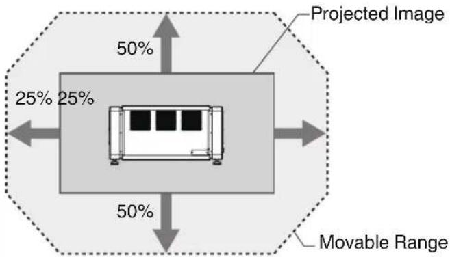
GL-MS4011S Short focal length lens
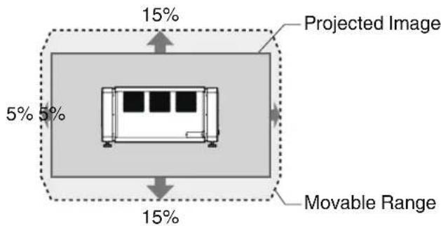

MEMO
- When using the lens shift feature, do not exceed the range (shift amount) as shown above. If the shift amount exceeds the range as shown, shadows will appear on the projected image.
Lens Fixation Mechanism
A screw for securing the lens mechanism is attached in the factory shipment to prevent damage of the equipment during transportation. If the lens does not move horizontally or vertically when you operate "Shift" in the "Lens" menu, this could be because the screw has not been removed. When this occurs, please consult your authorized dealer.
Overlaying projected images (when zoom lens is in use)
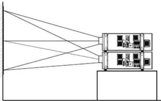
Projecting images by stacking projectors
The lens shift feature enables you to use up to three stacked projectors at the same time.
Stacking the projectors enhances the brightness level, and helps to project images that are sufficiently bright even when the venue is relatively big or bright.
flowchart
graph TD
    A["Server Unit 1"] --> B["Client 1"]
    A --> C["Client 2"]
    A --> D["Client 3"]
    A --> E["Client 4"]
    A --> F["Client 5"]
    B --> G["Processing Unit"]
    C --> G
    D --> G
    E --> G
    F --> G

CAUTION
- When the projectors are stacked together during use, ensure that the installation site is sufficiently strong and there is proper air cooling around the projectors. Take the necessary measures to prevent the projectors from toppling or falling off so as to ensure safety during emergency situations, such as earthquakes, and to prevent accidents from occurring. For details, please consult your authorized dealer.
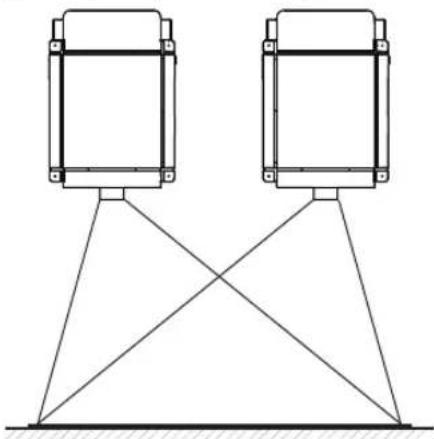
Projecting images by arranging projectors side by side
The lens shift feature enables you to use up to two projectors that are arranged side by side.
Arranging two projectors side by side enhances the brightness level, and helps to project images that are sufficiently bright even when the venue is relatively big or bright.
When projecting images by arranging the projectors side by side, adjust the shift amount of both projectors accordingly to superimpose the images.
natural_image
Pure technical line drawing of two identical structural components mounted on a truss base (no text or symbols)
CAUTION
- When using the projectors by arranging them side by side, ensure that the installation site is sufficiently strong and there is proper air cooling around the projectors. For details, please consult your authorized dealer.
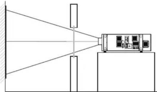
When light passes through the glass of projection booth
natural_image
Diagram of a system with a beam splitter and a control unit, no text or symbols present
MEMO
- When light passes through the glass, the quantity of light decreases. Make sure that the glass of the projection booth is not more than one piece.
- Do not use glass if possible.
- When projecting light on an inclined glass surface, adjust the glass angle as well as installation angle of this unit accordingly to prevent impact on the image due to diffuse reflection.
Screen Size and Projection Distance
Adjust the distance from the lens to the screen to achieve your desired screen size.
GL-MS4015SZ / GL-MS4016SZ / GL-MS4021SZ Zoom lens
| Projection Screen Size (Diagonal Length) | Image Width | Projection distance | |||||
| GL-MS4015SZ GL- | MS4016SZ GL-MS402 | 1SZ | |||||
| Tele End | Wide End | Tele End Wide | End Tele | End Wide End | End | ||
| 50" (Approx. 1.27 m) 1.10 | m - - 1.97 m 1.58 | m - - | |||||
| 60" (Approx. 1.53 m) 1.31 | m - - 2.37 m 1.92 | m - - | |||||
| 70" (Approx. 1.79 m) 1.54 | m - - 2.78 m 2.25 | m - - | |||||
| 80" (Approx. 2.03 m) 1.75 | m 3.19 m 2.58 m | 3.19 m 2.58 m | 6.38 m | 3.72 m | |||
| 90" (Approx. 2.29 m) 1.97 | m 3.60 m 2.91 m | 3.60 m 2.91 m | 7.19 m | 4.24 m | |||
| 100" (Approx. 2.54 m) 2.19 | m 4.01 m 3.25 m | 4.01 m 3.25 m | 8.01 m | 4.71 m | |||
| 110" (Approx. 2.79 m) 2.41 | m 4.42 m 3.58 m | 4.42 m 3.58 m | 8.82 m | 5.17 m | |||
| 120" (Approx. 3.05 m) 2.63 | m 4.83 m 3.91 m | 4.83 m 3.91 m | 9.63 m | 5.64 m | |||
| 130" (Approx. 3.30 m) 2.85 | m 5.24 m 4.25 m | 5.24 m 4.25 m | 10.44 m | 6.11 m | |||
| 140" (Approx. 3.56 m) 3.07 | m 5.65 m 4.58 m | 5.65 m 4.58 m | 11.25 m | 6.57 m | |||
| 150" (Approx. 3.81 m) 3.29 | m 6.06 m 4.91 m | 6.06 m 4.91 m | 12.06 m | 7.04 m | |||
| 160" (Approx. 4.06 m) 3.51 | m 6.46 m 5.25 m | 6.46 m 5.25 m | 12.87 m | 7.50 m | |||
| 170" (Approx. 4.32 m) 3.73 | m 6.87 m 5.58 m | 6.87 m 5.58 m | 13.68 m | 7.97 m | |||
| 180" (Approx. 4.57 m) 3.94 | m 7.28 m 5.91 m | - 5.91 m | 4.49 m | 8.44 m | |||
| 190" (Approx. 4.83 m) 4.16 | m 7.69 m 6.24 m | - 6.24 m | 15.30 m | 8.90 m | |||
| 200" (Approx. 5.08 m) 4.38 | m 8.10 m 6.58 m | - 6.58 m | 16.12 m | 9.44 m | |||
| 210" (Approx. 5.33 m) 4.60 | m 8.51 m 6.91 m | - 6.91 m | 16.93 m | 9.83 m | |||
| 220" (Approx. 5.59 m) 4.82 | m 8.92 m 7.24 m | - 17.74 m | 10.30 m | ||||
| 230" (Approx. 5.84 m) 5.04 | m 9.33 m 7.58 m | - 18.55 m | 10.77 m | ||||
| 240" (Approx. 6.10 m) 5.26 | m 9.74 m 7.91 m | - 19.36 m | 11.23 m | ||||
| 250" (Approx. 6.35 m) 5.48 | m 10.15 m 8.24 m | - 20.17 m | 11.70 m | ||||
| 260" (Approx. 6.60 m) 5.70 | m 10.55 m 8.58 m | - 20.98 m | 12.16 m | ||||
| 270" (Approx. 6.86 m) 5.92 | m 10.96 m 8.91 m | - 21.79 m | 12.63 m | ||||
| 280" (Approx. 7.11 m) 6.14 | m 11.37 m 9.24 m | - 22.60 m | 13.10 m | ||||
| 290" (Approx. 7.37 m) 6.36 | m 11.78 m 9.57 m | - 23.41 m | 13.56 m | ||||
| 300" (Approx. 7.62 m) 6.57 | m 12.19 m 9.91 m | - 24.23 m | 14.03 m | ||||

MEMO
- The distance indicated in the table is an estimated value when an image with a resolution of 4096 × 2400 is projected. Please use them as reference during installation.
GL-MS4011S Short focal length lens
| Projection Screen Size (Diagonal Length) Image Width Projection distance | |
| 50" (Approx. 1.27 m) 1.10 m 1.16 m | |
| 60" (Approx. 1.52 m) 1.31 m 1.41 m | |
| 70" (Approx. 1.78 m) 1.53 m 1.66 m | |
| 80" (Approx. 2.03 m) 1.75 m 1.91 m | |
| 90" (Approx. 2.29 m) 1.97 m 2.16 m | |
| 100" (Approx. 2.54 m) 2.19 m 2.41 m | |
| 110" (Approx. 2.79 m) 2.41 m 2.66 m | |
| 120" (Approx. 3.05 m) 2.63 m 2.91 m | |
| 130" (Approx. 3.30 m) 2.85 m 3.17 m | |
| 140" (Approx. 3.56 m) 3.07 m 3.42 m | |
| 150" (Approx. 3.81 m) 3.29 m 3.67 m | |
| 160" (Approx. 4.06 m) 3.51 m 3.92 m | |
| 170" (Approx. 4.32 m) 3.73 m 4.17 m | |
| 180" (Approx. 4.57 m) 3.94 m 4.42 m | |
| 190" (Approx. 4.83 m) 4.16 m 4.67 m | |
| 200" (Approx. 5.08 m) 4.38 m 4.92 m | |
| 210" (Approx. 5.33 m) 4.60 m 5.17 m | |
| 220" (Approx. 5.59 m) 4.82 m 5.43 m | |
| 230" (Approx. 5.84 m) 5.04 m 5.68 m | |
| 240" (Approx. 6.10 m) 5.26 m 5.93 m | |
| 250" (Approx. 6.35 m) 5.48 m 6.18 m |

MEMO
- The distance indicated in the table is an estimated value when an image with a resolution of 4096 × 2400 is projected. Please use them as reference during installation.
Connecting Video Signals of the Computer
Connection During Single-Screen Mode Display
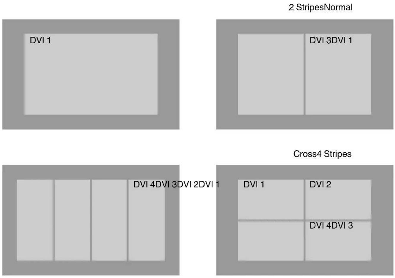
The single-screen mode displays signals (up to four signals) from a computer as a single video image.
To select to the single-screen mode, set "Display Mode" in the "Setting" menu to "Single". (P. 38)
Possible Input Signals and Projected Image
| Computer Projector | Terminal for Connection | Output Status | Displayed Projector Image | |||
| Resolution Channel Link Status | ||||||
| 4096×2400 | 2ch Dual | DVI 1, DVI 3 2 | Stripes 2048×2400 | 4096×2400*(8192×4800) | ||
| 4ch Single | DVI 1 to DVI 4 | Cross 2048×1200 | ||||
| 4 Stripes 1024×2400 | ||||||
| 4096×2160 | 2ch Dual | DVI 1, DVI 3 2 | Stripes 2048×2160 | 4096×2160*(8192×4320) | ||
| 4ch Single | DVI 1 to DVI 4 | Cross 2040×1080 | ||||
| 4 Stripes 1024×2160 | ||||||
| 3840×2400 | 2ch Dual | DVI 1, DVI 3 2 | Stripes 1920×2400 | 3840×2400*(7680×4800) | ||
| 4ch Single | DVI 1 to DVI 4 | Cross 1920×1200 | ||||
| 4 Stripes 960×2400 | ||||||
| 3840×2160 | 2ch Dual | DVI 1, DVI 3 2 | Stripes 1920×2160 | 3840×2160*(7680×4320) | ||
| 4ch Single | DVI 1 to DVI 4 | Cross 1920×1080 | ||||
| 4 Stripes 960×2160 | ||||||
| 2048×1200 1ch Single DVI 1 | Normal 2048×1200 4096×2400 | |||||
| 2048×1080 1ch Single DVI 1 | Normal 2048×1080 4096×2160 | |||||
| 1920×1200 1ch Single DVI 1 | Normal 1920×1200 3840×2400 | |||||
| 1920×1080 1ch Single DVI 1 | Normal 1920×1080 3840×2160 | |||||
| 1600×1200 1ch Single DVI 1 | Normal 1600×1200 3200×2400 | |||||
| 1280×1024 1ch Single DVI 1 | Normal 1280×1024 2560×2048 | |||||
| 1024×768 1ch Single DVI 1 | Normal 1024×768 2048×1536 | |||||
| 800×600 1ch Single DVI 1 | Normal 800×600 1600×1200 | |||||
| 640×480 1ch Single DVI 1 | Normal 640×480 1280×960 | |||||
* (DLA-VS4810) An 8K image is displayed when e-shift sync signal is input.

MEMO
- This projector converts the frame rate to 60 Hz regardless of the synchronizing signal frequency at the computer's end.
- If the resolution of the PC is 2048×1200 or lower, images are displayed upon doubling the number of the vertical and horizontal pixels.
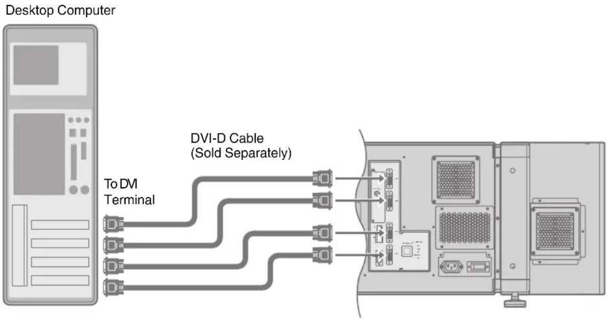
Connection During Single-Screen Mode Display
Below is the connection example for four-channel signals from the computer.
For two-channel signals from the computer, connect to the [DVI 1] and [DVI 3] terminals of this projector.
flowchart
graph LR
    A["Desktop Computer"] -->|To DVI Terminal| B["DVI-D Cable (Sold Separately)"]
    B --> C["Internal Components"]
    C --> D["Computer"]
    style A fill:#f9f,stroke:#333
    style B fill:#ccf,stroke:#333
    style C fill:#cfc,stroke:#333

MEMO
• Depending on your DVI-D cable, the signal may attenuate and the image become unstable.
- Use of DVI-D cables compliant with the DDWG standard is recommended.
Connection During Two-Screen/Four-Screen Mode Display
The two-screen/four-screen mode enables simultaneous display of signals from two or four computers.
To select the two-screen mode, set "Display Mode" in the "Setting" menu to "Double". To select the four-screen mode, set "Display Mode" to "Cross". (P. 38)
Possible Input Signals and Projected Image
| Computer | Output Status | |||
| Resolution Channel | Link Status | |||
| 2048×1200 1ch | Single Normal 2048×1200 | |||
| 2048×1080 1ch | Single Normal 2048×1080 | |||
| 1920×1200 1ch | Single Normal 1920×1200 | |||
| 1920×1080 1ch | Single Normal 1920×1080 | |||
| 1600×1200 1ch | Single Normal 1600×1200 | |||
| 1280×1024 1ch | Single Normal 1280×1024 | |||
| 1024×768 1ch | Single Normal 1024×768 | |||
| 800×600 1ch | Single Normal 800×600 | |||
| 640×480 1ch | Single Normal 640×480 | |||

MEMO
- This projector converts the frame rate to 60 Hz regardless of the synchronizing signal frequency at the computer's end.
- The respective signals are displayed at the center of the split screen.
- When in the two-screen mode, the screen appears blue (or black depending on the setting) when there is no input.
Two-Screen Mode Four-Screen Mode
(Example) DVI 1: 1920×1080, DVI 3: 1920×1080
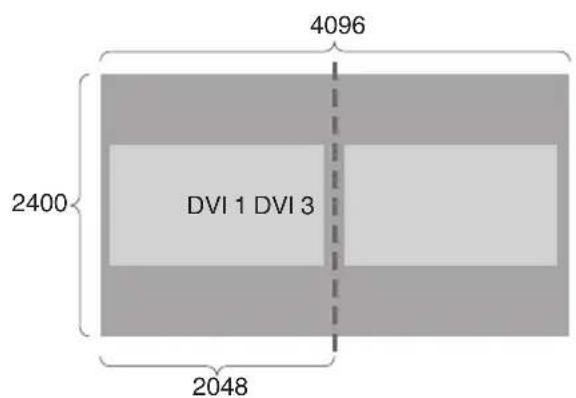
other
| Section | Dimension | |---|---| | DVI 1 | 2400 | | DVI 3 | 4096 | | Total Length | 2048 |(Example) DVI 1: 2048×1200, DVI 2: 1920×1080, DVI 3: 1024×768, DVI 4: 1600×1200
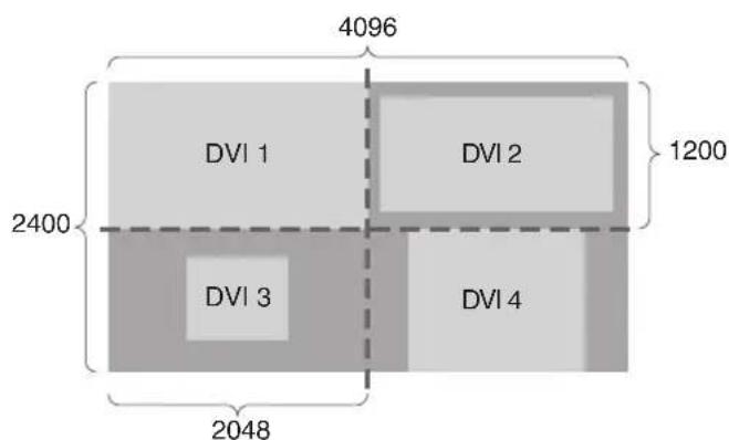
other
| Category | Value | |---|---| | DVI 1 | 4096 | | DVI 2 | 1200 | | DVI 3 | 2400 | | DVI 4 | 2048 | The chart displays a single numerical value for each unit within the grid. The values are explicitly labeled as 4096, 2400, and 2048.Connection Example During Two-Screen Mode
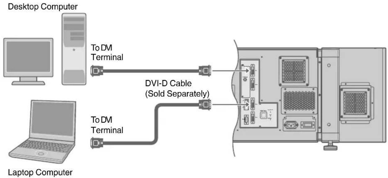
flowchart
graph LR
    A["Desktop Computer"] -->|To DM Terminal| B["DVI-D Cable (Sold Separately)"]
    C["Laptop Computer"] -->|To DM Terminal| B
    B --> D["Computer"]
Connection Example During Four-Screen Mode
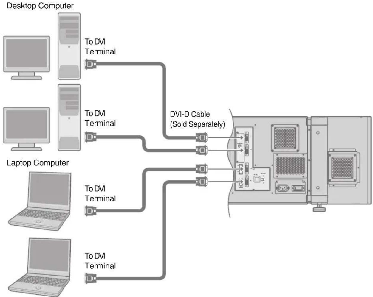
flowchart
graph TD
    A["Desktop Computer"] --> B["To DVI Terminal"]
    C["Laptop Computer"] --> D["To DVI Terminal"]
    E["Laptop Computer"] --> F["To DVI Terminal"]
    G["Desktop Computer"] --> H["DVI-D Cable (Sold Separately)"]
    I["Laptop Computer"] --> J["To DVI Terminal"]
    K["Desktop Computer"] --> L["To DVI Terminal"]
    M["Desktop Computer"] --> N["To DVI Terminal"]

MEMO
- Depending on your DVI-D cable, the signal may attenuate and the image become unstable.
- Use of DVI-D cables compliant with the DDWG standard is recommended.
Connection Using a LAN Cable
Connect this projector, the computer for controlling this projector, and the switching hub using LAN cables, followed by configuring the network.
Connection Example
When assigning a static IP address
You can acquire the IP address from the controlling computer simply by configuring a network that consists of this projector, the controlling computer, and switching hub. Please refer to technical books on networks for details.
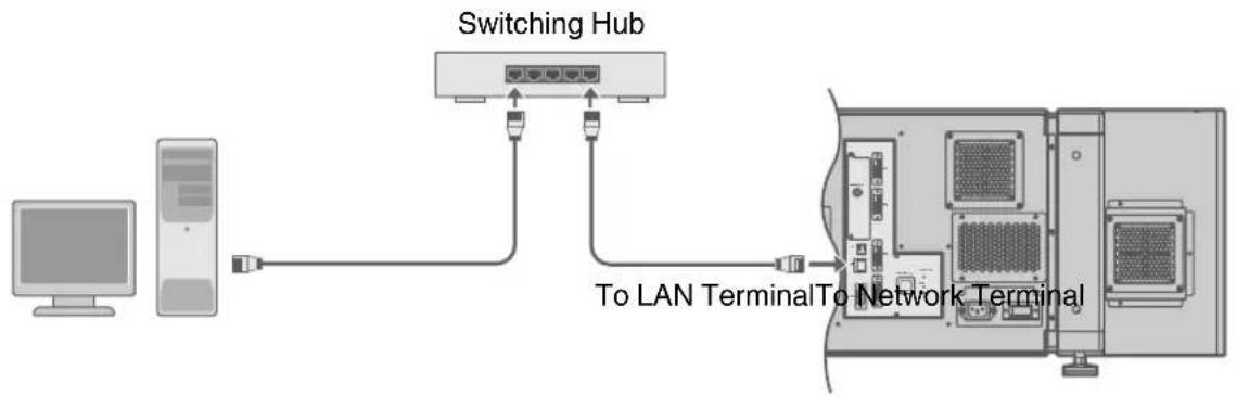
flowchart
graph LR
    A["Computer"] --> B["Switching Hub"]
    B --> C["To LAN Terminal"]
    C --> D["Network Terminal"]
    style A fill:#f9f,stroke:#333
    style B fill:#ccf,stroke:#333
    style C fill:#cfc,stroke:#333
    style D fill:#fcc,stroke:#333

MEMO
- Make use of Cat. 5 (equivalent or higher) straight 100Base-TX LAN cables.

CAUTION
- When connecting this projector and the controlling computer for this projector using other network, be sure to consult the network administrator of the network in use or refer to technical books on networks.
When assigning IP address from the DHCP server
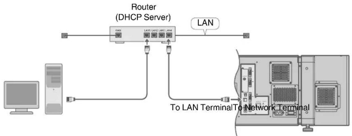
flowchart
graph TD
    A["Computer"] --> B["Server"]
    B --> C["Router (DHCP Server)"]
    C --> D["LAN"]
    C --> E["To LAN Terminal"]
    C --> F["To Network Terminal"]

MEMO
• Make use of Cat. 5 (equivalent or higher) 100Base-TX LAN cables.
Specifications of PC for Controlling this Projector
OS Windows 7 (32-bit, 64-bit), Windows 8 (32-bit, 64-bit), Windows 10 (32-bit, 64-bit)
Browser Internet Explorer 10, Internet Explorer 11, Google Chrome, Firefox

MEMO
- Windows is either registered trademark or trademark of Microsoft Corporation in the United States and/or other countries.

CAUTION
- The PC specifications above are reference values for the application software to run smoothly, and are not intended to guarantee their operation. Note that the applications may not run smoothly depending on the condition of use of the respective users even when the system requirements are satisfied.
Turning On the Main Power
1 Check to ensure that this projector, computer, and switching hub are properly connected
2 Connect the power cord to the power input terminal of this projector
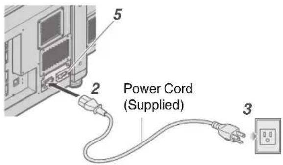
CAUTION
- Do not connect the power cord when a lens (optional) is not attached.
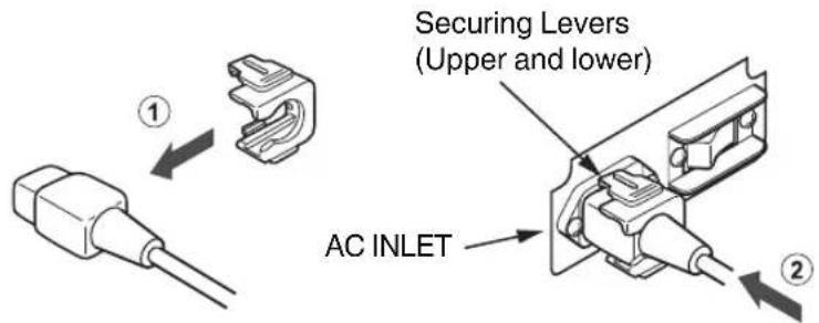
You can secure the power cord to this projector.
① Attach the plug holder to the power cord.
② Insert the plug holder into the projector until the upper and lower securing levers are locked.
3 Insert plug into the power outlet on the wall
4 Remove the lens cap
5 Turn on the main power of the projector to set to [I]
- The [STANDBY/ON], [LAMP] and [WARNING] indicators light up for about 45 seconds. Thereafter, only the [STANDBY/ON] indicator lights up in red.
MEMO
- The default IP address of all DLA-VS4010 / DLA-VS4810 is "192.168.0.2". If multiple units of DLA-VS4010 / DLA-VS4810 are used on the same network, do not turn on the main power of more than one projector unit at the same time. Doing so will result in duplication of the IP address, and thereby preventing proper access.
- When using multiple units of DLA-VS4010 / DLA-VS4810, turn on the main power of the second unit and configure accordingly only after configuration of the first unit is complete. Configure subsequent units using the same procedure.
- When duplication occurs in the IP address, make sure that only one unit of DLA-VS4010 / DLA-VS4810 is connected on the same network (turn off the main power of the other DLA-VS4010 / DLA-VS4810 units). Allow a time interval of at least 10 minutes before accessing. If access fails, turn off the power of all network equipments on the same network, followed by turning them on again.
IP Address Settings
Set the IP address for this projector. There are 2 methods to set the IP address.
- Assigning a static IP address
- Assigning IP Address from the DHCP Server
Assigning a static IP address
The "IP Address Setting" of this projector is set to "STATIC IP" (the DHCP client function is OFF) by default.
Upon turning on the power, this projector starts running with the following IP address.
IP Address : 192.168.0.2
Subnet Mask : 255.255.255.0
Default Gateway : 192.168.0.254
IP address setting at the computer
Set the computer to an IP address that enables communication with this projector.
1 Click "Start" and select "Control Panel"
2 Double click "Network Connections"
3 Right-click on "Local Area" and select "Properties"
- Check to ensure that the "Client for Microsoft Networks" and "Internet Protocol(TCP/IP)" check boxes are selected.
4 Select "Internet Protocol(TCP/IP)" and click "Properties"
5 Set the IP address
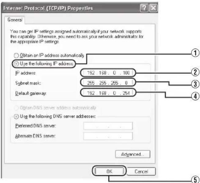
① Select "Use the following IP address"
② Set "IP address"
(For example, use 192.168.0.100 when DLA-VS4010 / DLA-VS4810 is in its default settings)
MEMO
• Make sure that you take note of the original IP address before altering.
- When setting, ensure that a duplicate IP address is not used within the same network environment.
③ Set "Subnet mask"
Set toa value that is appropriate for the setting operation. Clarify with the network administrator if you have any queries.
(Use 255.255.255.0 when the camera is in its default settings)
④ When a "Default gateway" is present, make use of the IP address (e.g., 192.168.0.254)
⑤ Click "OK"
6 Click "OK" on the "Local Area Connection Properties" screen
Setting (Changing) the IP address of this projector
When using Internet Explorer
1 Launch the Internet Explorer on the computer
2 Check if the proxy has been set in the "LAN Setting" of the Internet Explorer
① Click "Tools" and select "Internet Options"
② Click "Connections" and click "LAN Setting"
③ Check if the check for "Use a proxy server for your LAN" has been selected
- If the check mark has been selected, deselect it.
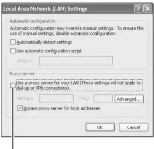
Deselct the check
3 Check if the "Active scripting" of the Internet Explorer is disabled
① Click "Tools" and select "Internet Options"
② Click in the order of "Security" → "Trusted Sites" → "Sites"
③ Deselect the check "Required server verification (https:) for all sites in this zone"
④ Enter "http://192.168.0.2" under "Add this web site to the zone" and click "Add"
⑤ Click "OK"
⑥ Select "Trusted Sites" and click "Custom Level"
⑦ Check if the check for "Active scripting" under "Scripting" has been selected
- If the check mark has been deselected, select it.
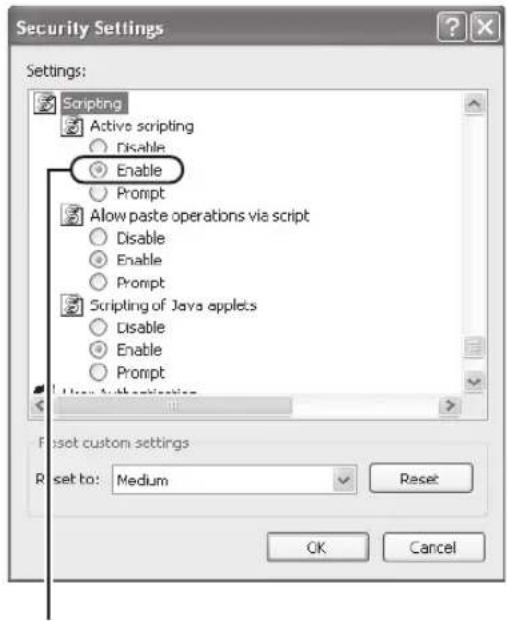
Select "Enable"
4
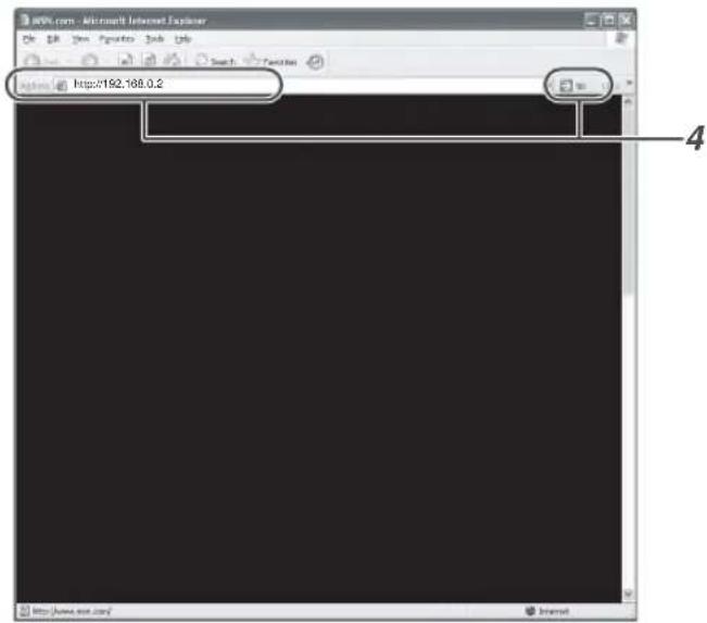
Enter "http://192.168.0.2" in the address field of the Internet Explorer, and click "Go"
• A login screen for this projector appears.

MEMO
- When "LAN Setting" in Internet Explorer is set to "Use a proxy server for your LAN" it may not be possible to designate addresses directly. Change the proxy settings.
- If a "Security Warning" screen appears, click "OK" and continue.
5 Enter "advanced" in "Login Name"
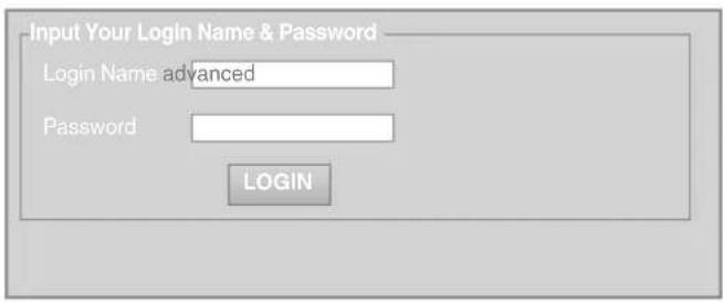
6 Click "LOGIN"
- The "Main" menu for this projector appears.

MEMO
- You can alter the user name and password in the "Admin.Network" menu. Specify a user name and password of not more than eight single-byte alphanumeric characters. (P. 43)
- If you have forgotten the password, please consult your authorized dealer.
7
Click "Admin.Network" in the "Main" menu
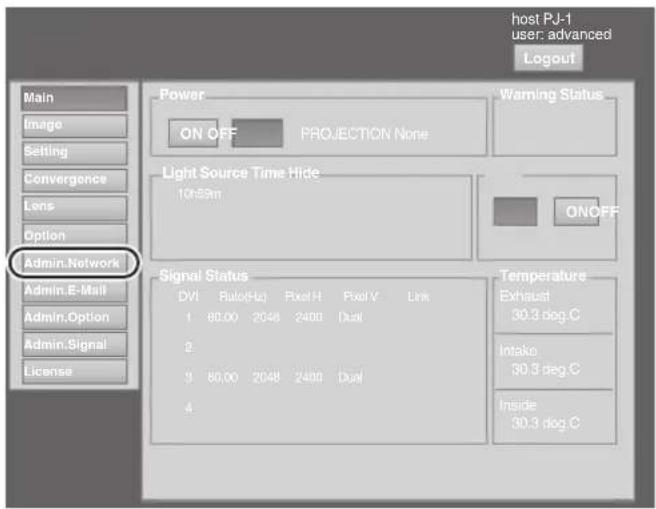
8
Set the IP address for this projector
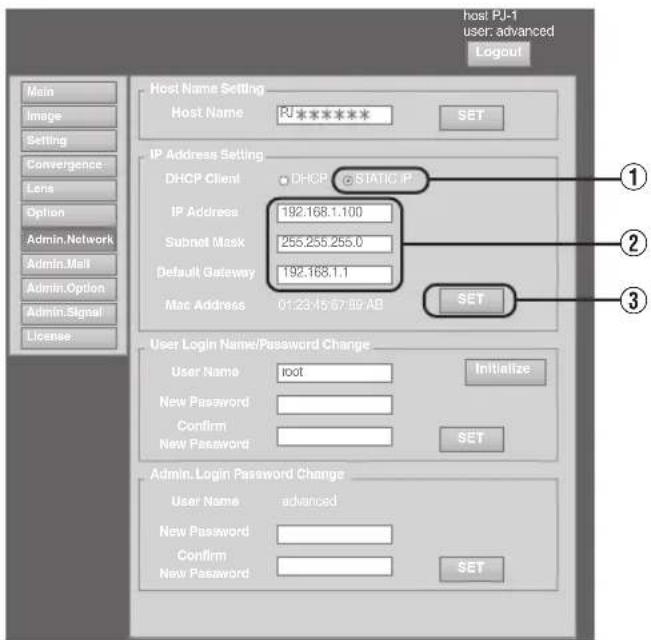
① Select "STATIC IP" in "DHCP Client"
② Enter the values for "IP Address", "Subnet Mask" and "Default Gateway"
③ Click "SET"

MEMO
- Access from computers may not be successful as this projector's IP address has been changed. Set and change the computer's IP address when accessing this projector.
Assigning IP Address from the DHCP Server
The IP address is automatically assigned by the DHCP server.
1 After connecting, turn on the main power
• Refer to P. 22 on the details of connection.
• Refer to P. 24 on procedures to turn on the main power.
2 Set the "DHCP Client" setting of this projector to "DHCP"
- The “DHCP Client” of this projector is set to “STATIC IP” (the DHCP client function is OFF) by default. When assigning an IP address from the DHCP server, access this projector from the computer to alter the settings. For details on the setting procedures, refer to “Setting (Changing) the IP address of this projector” P. 26.

MEMO
- Please consult the network administrator on the IP address assigned to this projector.
- When "DHCP Client" is set to "DHCP", and if the projector is started up in a LAN where a DHCP server does not exist, the projector will start up using the default IP address instead.

CAUTION
- Configure the DHCP server such that the same IP address is assigned to the “Mac Address” of this projector by the DHCP server at all times. Connection may fail if the above setting is not performed.
Connecting this projector and the computer using a USB cable
You can connect this projector and the controlling computer using a USB cable.
- You need to install a driver in order to connect the projector and computer using a USB cable.

MEMO
- For details on the installation of the USB driver, please consult your authorized dealer.
Using the Mail Delivery Feature
This feature enables delivery of mail (error message) to the preset e-mail address when error occurs inside this projector unit.
Connection Example (When DHCP Server is Used)
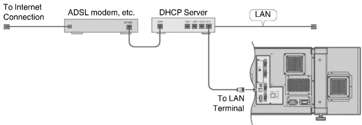
flowchart
graph LR
    A["To Internet Connection"] --> B["ADSL modem, etc."]
    B --> C["ETHER"]
    B --> D["DHCP Server"]
    D --> E["LAN"]
    D --> F["To LAN Terminal"]
Projecting Image
If setting for this projector is not completed, refer to "User Settings Menu" P. 34 upo turning on the power and configure the settings accordingly.
Once the basic settings are configured, this projector can be used by simply performing the following operation procedures.
- Remove the lens cap.
- Connect this projector to the computer. (P. 19, 21)
- Connect the LAN cable. (P. 22)
1 Set this projector to the standby mode, and display the "Main" menu
- Refer to "Turning On the Main Power" P. 24, and steps 4 to 6 of "Assigning a static IP address" P. 25.
• The [STANDBY/ON] indicator lights up in red.
2 Click the "ON" button under the "Power" item of the "Main" menu to project the image
- The power of this projector turns on, and formatting is done taking a few minutes. A gray image will be displayed during formatting. The projected image appears once formatting ends.
- The [STANDBY/ON] indicator lights up in green.
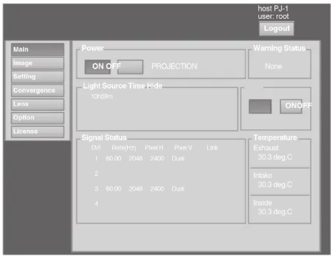

MEMO
- You can also turn on the power by pressing the [OPERATEI/⏻] button on the projector unit for more than one second.
- The image may flicker for a few seconds immediately after projection starts. This is not a malfunction.
- After the LD block lights up, it takes more than 1 minute for the brightness of the video image on the screen to stabilize.
3 Adjust the zoom ratio (screen size) (when zoom lens is in use)
You can adjust the focus using the "Zoom" item of the "Lens" menu.
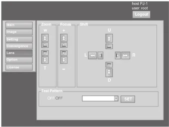
To enlarge the screen size:
Press the "W" (Wide) end of "Zoom"
To reduce the screen size:
Press the "T" (Tele) end of "Zoom"

MEMO
- The screen size changes each time you click on the inner buttons ( / ). (Fine control) The outer buttons ( / ) change the screen size when they are depressed. (Coarse control)
4 Adjust the position of the projection screen
You can adjust the focus using the "Shift" item of the "Lens" menu.
To shift the image upward:
Press the "U" end of "Shift"
To shift the image downward:
Press the "D" end of "Shift"
To shift the image rightward:
Press the "R" end of "Shift"
To shift the image leftward:
Press the "L" end of "Shift"

MEMO
- When a zoom lens is used, the adjustment range for lens shift is between 0 % to ±50 % in the vertical direction, and between 0 % to ±25 % in the horizontal direction (during single-screen display).
- When a short focal length lens is used, the adjustment range for lens shift is between 0 % to ±15 % in the vertical direction, and between 0 % to ±5 % in the horizontal direction (during single-screen display). (P. 14)
- The position changes each time you click on the inner buttons ( / ). (Fine control)
- The image shifts when the outer buttons (△/▽) are depressed. (Coarse control)
- The lens shift feature does not function if the lens mechanism is secured ("Lens Fixation Mechanism" P. 14)
5 Adjust the focus
You can adjust the focus using the "Focus" item of the "Lens" menu.
To move the focus point closer:
Press the “+” (Near) end of “Focus”
To move the focus point away:
Press the “-” (Far) end of “Focus”

MEMO
- The focus changes each time you click on the inner buttons (△ /▽). (Fine control)
The outer buttons (△/▽) change the focus when they are depressed. (Coarse control)
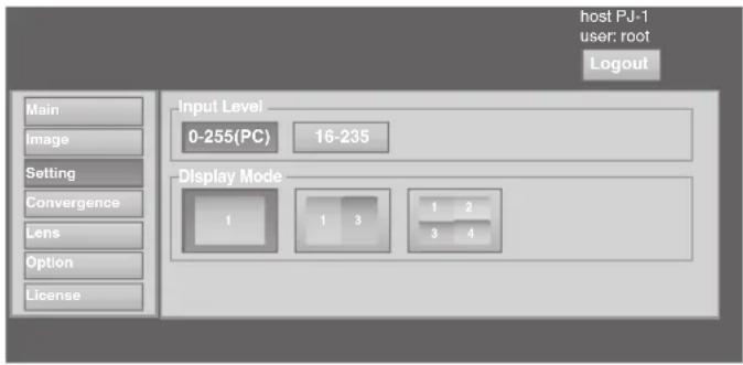
6 Select a screen mode for projection
You can specify the screen mode using "Display Mode" of the "Setting" menu. (P. 38)

MEMO
- The projected image varies according to the mode of connection. (P. 19, 21)
7 Click the "OFF" button under the "Power" item of the "Main" menu to end the projection
- The projector switches to the cool down mode, and the [STANDBY/ON] indicator appears blinking in red.
- A gray image will be displayed for a maximum duration of 2 minutes during the ending process only after seven hours of image projection. Thereafter, the LD block starts to cool down.
- After exiting the cool down mode, the projector switches automatically to the standby mode, and the [STANDBY/ON] indicator lights up in red.
- You can also turn off the power by pressing the [OPERATEI/∅] button on the projector unit for more than one second.
Cool down mode
Cool down mode is a function that cools down the LD block for about 10 seconds after projection ends (ending process).
- When the projector is in the cool down mode, the [STANDBY/ON] indicator appears blinking in red.
- Do not shut down the main power supply or unplug the power cord when in the cool down mode. Also, do not block the air inlets and vent holes. Doing so may shorten the lamp life and cause a malfunction.
8 Turn the main power at the rear of the projector unit to off [O]
- The [STANDBY/ON] indicator on the projector unit goes off.
![JVC DLA-VS4010 - Turn the main power at the rear of the projector unit to off [O] - 1](/content/2026/05/976320/images/ebc6f3c94053b892e4ebbd36d0fd5219b9ae481203def482a5ff3a5f8394fb40.jpg)
CAUTION
- Do not turn off the main power supply switch when in the cool down mode. Doing so may shorten the lamp life and cause a malfunction.
- Upon using, attach the lens cap to prevent soiling of the lens.
- When the projector is not to be used for a long time, disconnect the power plug.
Useful Features During Projection
Hiding the projected image temporarily
The projected image can be hidden by clicking the "ON" button under the "Hide" item of the "Main" menu or "Image" menu.
- When the image is not displayed, pressing "OFF" under the "Hide" item to display the hidden image.

MEMO
When the image is hidden, the [STANDBY/ON] indicator appears blinking in green.
Displaying the Menu
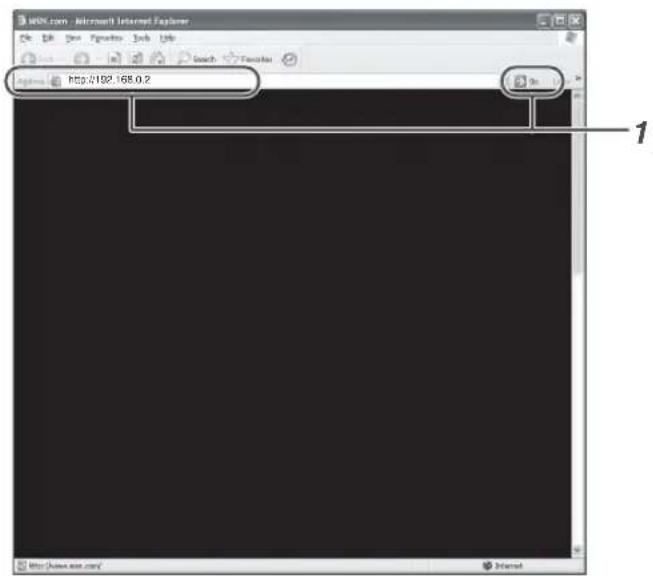
1
Enter the IP address assigned in the address field of the Internet Explorer, and click "Go" (P. 27)
- Example: When IP address assigned is "192.168.0.2", enter "http://192.168.0.2".

MEMO
- When "LAN Setting" in Internet Explorer is set to "Use a proxy server for your LAN" it may not be possible to designate addresses directly. Change the proxy settings.
- If a "Security Warning" screen appears, click "OK" and continue.
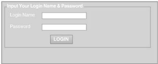
2
Enter the login name and the password in the "Login Name" and "Password" fields respectively

MEMO
• If you have forgotten the password, please consult your authorized dealer.
3
Click "LOGIN"
- The "Main" menu for this projector appears.

MEMO
- You can alter the user name and password in the "Admin.Network" menu. Specify a user name and password of not more than eight single-byte alphanumeric characters. (P. 43)
User Settings Menu
After installation and connection are complete, perform the necessary adjustment and setting.
Operate the menus using the computer's browser to make adjustments and configure settings.
User Settings Menu Structure
| Page Menu Name Page Display Item Simplified Description of Item | ||
| (1) Main Power | Warning StatusLight Source TimeSignal StatusTemperatureHide | Power ON/OFF operationError code displayLD block information displayInput signal information displayProjector's interior temperature displayMute operation |
| (2) Image Brightness | ContrastGammaHide | Brightness adjustmentContrast adjustmentGamma settingMute operation |
| (3) Setting Input Level | Display Mode | Input level settingDisplay method setting |
| (4) Convergence Red | BlueTest Pattern | Pixel position adjustmentPixel position adjustmentTest pattern setting |
| (5) Lens Zoom | FocusShiftTest Pattern | Zoom adjustmentFocus adjustmentImage position adjustmentTest pattern setting |
| (6) Option Flip | Light Source PowerBack ColorMessage DisplayTest Pattern | Image inversion settingLD block power settingBackground color settingMessage display settingTest pattern setting |
(1) Main Menu
This menu displays the ON/OFF status of the power supply and information on signals input to the projector.
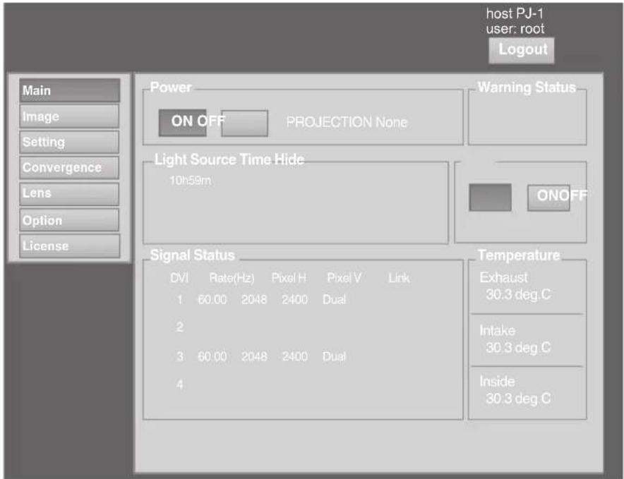

MEMO
- When the power of this unit is off (main power is on), the "Main", "Image", "Setting", "Convergence", "Lens" and "Option" menus will be grayed out and will not be selectable.
| Item Setting Value | Description | |
| Power | ONOFF | Turns on/off the LD block.ON : Turns on the LD block.OFF : Turns off the LD block.MEMOThe following operating modes of the projector are displayed to the right of the “OFF” button.STANDBY : Standby (OFF)PROJECTION : LD block illuminated (ON)FAN ENABLE : FAN Enable (OFF → ON)DEVICE ENABLE : Elemental Device Enable (OFF → ON)COOLING : Cooling (OFF)EMERGENCY : Error Occurred (Cooling not performed)EMERGENCY COOLING : Error Occurred (Cooling performed)When in the standby mode, clicking the “ON” button each time switches the mode in the sequence of “STANDBY” → “DEVICE ENABLE” → “FAN ENABLE” → “PROJECTION”.Clicking the “OFF” button when the power is on switches the projector to the cooling mode. The power of the projector cannot be turned on during the cooling process (10 seconds). |
● indicates the factory default.
| Item Setting Value Description | ||
| Warning Status - Displays the latest error number. | MEMOFor details on the error code and description, please refer to “Warning Status”P. 54.“None” is displayed when no error is detected. | |
| Light Source Time - Displays the lifetime of the LD block. | ||
| Signal StatusDVIRate(Hz)Pixel HPixel VLink | - | Displays information on the input signals.DVI : Displays the DVI input terminal number.Rate(Hz) : Displays the vertical frequency.Pixel H : Displays the horizontal resolution.Pixel V : Displays the vertical resolution.Link : Displays the link status of the DVI terminal.MEMOThis item is not displayed when there is no signal input.The text color of “Rate(Hz)” (vertical frequency) turns red in the case of interlaced signal. And the text turns white in the case of progressive signal. |
| TemperatureExhaustIntakeInside | - | Displays the interior temperature of the projector.Exhaust : Temperature at the vent holesIntake : Temperature at the air inletsInside : Internal temperatureMEMOThe color of the text turns red if the temperature becomes abnormal.The text appears white at normal temperature. |
| Hide ● OFF | ON | Enables temporary hiding of the image.OFF : Do not hide image.ON : Hide image.MEMOWhen the image is hidden, the [STANDBY/ON] indicator appears blinking in green. |
(2) Image Menu
This menu is used for adjusting the image quality.
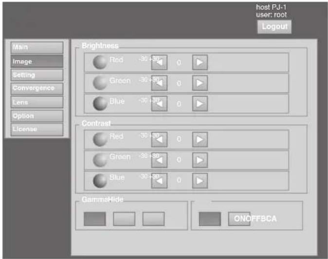
- indicates the factory default.
| Item Setting Value Description | ||
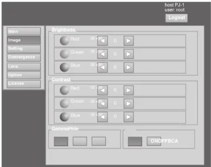
| BrightnessRedGreenBlue | -30 to +30(Default Value: 0)-30 to +30(Default Value: 0)-30 to +30(Default Value: 0) | For adjusting the brightness of the red, green, and blue colors. |
| ContrastRedGreenBlue | -30 to +30(Default Value: 0)-30 to +30(Default Value: 0)-30 to +30(Default Value: 0) | For adjusting the contrast of the red, green, and blue colors. |
| Gamma ● A | B C | For specifying the tone characteristics of the image.A : Sets gamma to “2.2”.B : Sets gamma to “1.8”.C : Sets gamma to “2.6”. |
| Hide ● OFF | ON | Enables temporary hiding of the image.OFF : Do not hide image.ON : Hide image.MEMOWhen the image is hidden, the [STANDBY/ON] indicator appears blinking in green. |
(3) Setting Menu
This menu is used for specifying the input level of the terminal and the display mode.
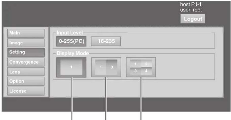
Single Double Cross
● indicates the factory default.
| Item Setting Value Description | ||
| Input Level ● 0-255(PC) | 16-235 | For specifying the input level of the video signals.0-255(PC): Set to this value under normal circumstances. (Signal level 0 to 255)16-235: For specifying when the signal level is between 16 and 235. |
| Display Mode ● Single | DoubleCross | For specifying the display mode of the projection screen.Single: Displays input signals on a single screen.Double: Displays two different input signals on two screens.The left screen displays images of the [DVI 1] terminal, and the right screen displays images of the [DVI 3] terminal.Cross: Displays four different input signals on four screens.The top left screen displays images of the [DVI 1] terminal, the top right screen displays images of the [DVI 2] terminal, the bottom left screen displays images of the [DVI 3] terminal, while the bottom right screen displays images of the [DVI 4] terminal.MEMOPlease refer to “Connecting Video Signals of the Computer” for details. (P. 18 to 21) |
(4) Convergence Menu
This menu is used for correcting color shifts in the optical system.
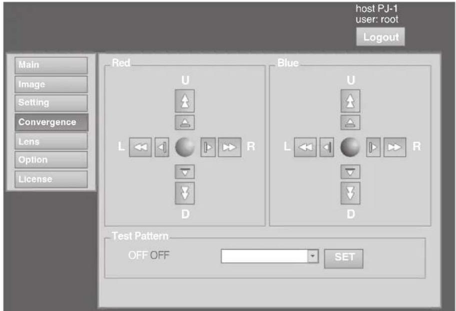
● indicates the factory default.
| Item Setting Value Description | ||
| Red - For adjusting the | horizontal/vertical position of red and blue colors on the image. | |
| Blue - | MEMOThe green color value is fixed.The outer buttons are used for adjustment in units of 1/4 pixels, and the inner buttons in units of 1/10 pixels.When the image is flipped horizontally or vertically, the horizontal and vertical directions are reversed.Use images with a clear outline (such as Color Cross Hatch patterns available in this projector) for adjustment.CAUTIONWhen themovement exceeds the limit, the color of the button turns red. | |
| Test Pattern ● OFF | Color BarsColor Cross HatchCross HatchStaircaseRampFlat | For projecting the test pattern.OFF : Do not display the test pattern.Color Bars : Displays the color bar.Color Cross Hatch : Displays the color cross hatch pattern.Cross Hatch : Displays the cross hatch pattern.Staircase : Displays the staircase (white color).Ramp : Displays the ramp pattern (white color).Flat : Displays the flat pattern (white color). |
(5) Lens Menu
This menu is used for adjusting the projection lens.
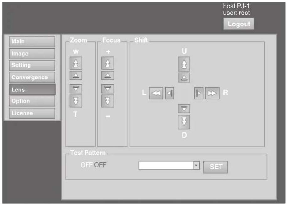
| Item Setting Value Description | |
| Zoom - For adjusting the zoom ratio (screen size). | MEMOThe zoom position changes each time the inner button is clicked.The zoom position changes when the outer button is depressed.CAUTIONDue to backlash, the response may not be immediate. |
| Focus - For adjusting the focus position. | MEMOThe zoom position changes each time the inner button is clicked.The zoom position changes when the outer button is depressed.CAUTIONDue to backlash, the response may not be immediate. |
| Shift - For adjusting the horizontal and vertical positions of the projection screen. | MEMOThe zoom position changes each time the inner button is clicked.The zoom position changes when the outer button is depressed.CAUTIONWhen the movement exceeds the limit, the color of the button turns red.Due to backlash, the response may not be immediate. |
| Test Pattern - For projecting the test pattern. | MEMOSame as “Test Pattern” in the “Convergence” Menu. (P. 39) |
(6) Option Menu
This menu is used for specifying the settings for screen display method, LD block brightness and others.
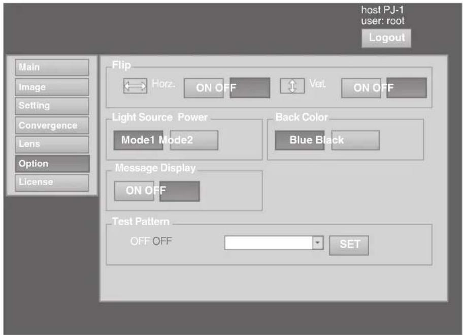
● indicates the factory default.
| Item Setting Value Description | ||
| Flip Horz. Vert. | ON● OFFON● OFF | For specifying settings if images are vertically or horizontally flipped when they are projected from the opposite side of the screen, or when mirrors are used for projection.ON: Flips image horizontally.OFF: Do not flip image horizontally.ON: Flips image vertically.OFF: Do not flip image vertically. |
| Light Source Power ● | Mode1 Mode2 | For switching the brightness of the LD block to “Mode1” or “Mode2”. Mode1: Brightness (high) Mode2: Brightness (low) |
| Back Color ● Blue | Black | For specifying the background color during message display or when projection fails, such as when there is no input signal.Blue: Sets the screen to blue color.Black: Sets the screen to black color. |
| Message Display | ON● OFF | For specifying whether to display the message.ON: Displays message.OFF: Does not display messages.CAUTIONWhen “OFF” is set, the “No Input”, “Out of Range” and “Lamp Time Over” messages will not be displayed on the screen. |
| Test Pattern - | For projecting the test pattern.MEMOSame as “Test Pattern” in the “Convergence” Menu. (P. 39) | |
Administrator Settings Menu
After installation and connection are complete, perform the necessary adjustment and setting.
Operate the menus using the computer's browser to make adjustments and configure settings.
Administrator Settings Menu Structure
For details on page menu (1) to (6), refer to "User Settings Menu" (P. 34 to 41).
| Page Menu Name Page Display Item Simplified Description of Item | ||
| (1) Main Power | Warning StatusLight Source TimeSignal StatusTemperatureHide | Power ON/OFF operationError code displayLD block information displayInput signal information displayProjector's interior temperature displayMute operation |
| (2) Image Brightness | ContrastGammaHide | Brightness adjustmentContrast adjustmentGamma settingMute operation |
| (3) Setting Input Level | Display Mode | Input level settingDisplay method setting |
| (4) Convergence Red | BlueTest Pattern | Pixel position adjustmentPixel position adjustmentTest pattern setting |
| (5) Lens Zoom | FocusShiftTest Pattern | Zoom adjustmentFocus adjustmentImage position adjustmentTest pattern setting |
| (6) Option Flip | Light Source PowerBack ColorMessage DisplayTest Pattern | Image inversion settingLD block power settingBackground color settingMessage display settingTest pattern setting |
| (7) Admin.Network Host Name Setting | IP Address SettingUser Login Password ChangeAdmin. Login Password Change | Host name settingIP address settingUser login settingAdministrator login setting |
| (8) Admin.E-mail E-Mail Setting | Test Mail | E-mail settingTest e-mail setting |
| (9) Admin.Option Color Depth | Frame LockMecha. ShutterHigh AltitudeLight Source Time Reset | Color balance settingFrame synchronization settingMechanical shutter settingHigh altitude mode settingResetting the lifetime of LD block |
| (10) Admin.Signal Force Signal | Display ModeSignal StatusEDID | Input/output signal settingDisplay method settingInput signal information displayEDID information rewrite |
| Page Menu Name Page Display Item Simplified Description of Item | ||
| (1) Main Power | Warning StatusLight Source TimeSignal StatusTemperatureHide | Power ON/OFF operationError code displayLD block information displayInput signal information displayProjector's interior temperature displayMute operation |
| (2) Image Brightness | ContrastGammaHide | Brightness adjustmentContrast adjustmentGamma settingMute operation |
| (3) Setting Input Level | Display Mode | Input level settingDisplay method setting |
| (4) Convergence Red | BlueTest Pattern | Pixel position adjustmentPixel position adjustmentTest pattern setting |
| (5) Lens Zoom | FocusShiftTest Pattern | Zoom adjustmentFocus adjustmentImage position adjustmentTest pattern setting |
| (6) Option Flip | Light Source PowerBack ColorMessage DisplayTest Pattern | Image inversion settingLD block power settingBackground color settingMessage display settingTest pattern setting |
| (7) Admin.Network Host Name Setting | IP Address SettingUser Login Password ChangeAdmin. Login Password Change | Host name settingIP address settingUser login settingAdministrator login setting |
| (8) Admin.E-mail E-Mail Setting | Test Mail | E-mail settingTest e-mail setting |
| (9) Admin.Option Color Depth | Frame LockMecha. ShutterHigh AltitudeLight Source Time Reset | Color balance settingFrame synchronization settingMechanical shutter settingHigh altitude mode settingResetting the lifetime of LD block |
| (10) Admin.Signal Force Signal | Display ModeSignal StatusEDID | Input/output signal settingDisplay method settingInput signal information displayEDID information rewrite |
(7) Admin.Network Menu
For configuring the network settings.
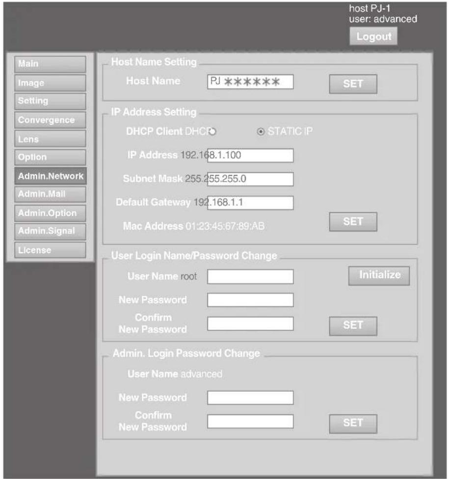
● indicates the factory default.
| Item Setting Value Description | ||
| Host Name Setting Host Name | - (Default Value: PJ******) | For specifying the host name. MEMOYou can change it to a random name. You can input up to 8 characters using single-byte alphanumeric characters and “-”. “*****” of the default value displays the lower 3 bytes of the MAC address of this projector. |
| IP Address Setting DHCP ClientIP Address Subnet Mask Default Gateway Mac Address | DHCP● STATIC IP(Default Value: 192.168.0.2)(Default Value: 255.255.255.0)(Default Value: 192.168.0.254)- | For configuring the network settings.DHCP : Select this to acquire the IP address from the DHCP server automatically.STATIC IP : Select this to configure the IP address manually.IP Address : Specify the IP address.Subnet Mask : Specify the subnet mask.Default Gateway : Specify the default gateway.Mac Address : Displays the MAC address.(Cannot be specified) |
| User Login Name/Password ChangeUser NameNew PasswordConfirm New Password Initialize | root-- | For changing the login name and password.User Name : For changing the login name.New Password : For changing the login password.Confirm New : Re-enter the new password. (For Password confirmation)Initialize : For resetting the username/password. MEMOYou can change it to a random name. You can input up to 8 characters using single-byte alphanumeric characters and “!”.If you have forgotten the password, please consult your authorized dealer. |
| Admin. Login Password ChangeUser NameNew PasswordConfirm New Password Initialize | advanced-- | For changing the administrator's password.User Name : Cannot be changed.(fixed)New Password : For changing the login password.Confirm New : Re-enter the new password. (For Password confirmation)Initialize : For resetting the password. MEMOYou canchange it to a random name. You can input up to 8 characters using single-byte alphanumeric characters and “!”.If you have forgotten the password, please consult your authorized dealer. |
(8) Admin.E-mail Menu
This menu is for configuring the mail settings, which sends out an error message to the computer of the preset address when an abnormality occurs within this projector.
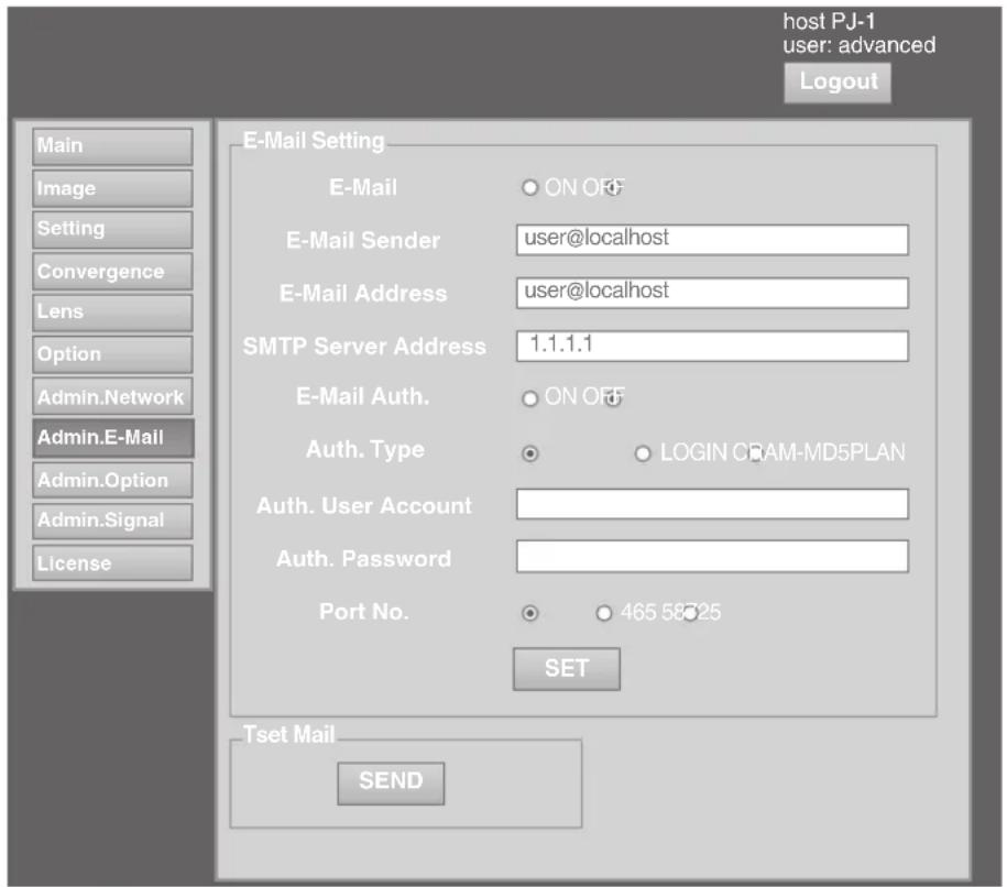
Error message sent from this projector
(Example) When error occurs at the DD-RB board
Sender
***** (setting value for "E-Mail Sender")
Mail title
4KPJU2 report mail
Message
Error Code 32 "Trouble with DD-RB circuit board."
System Time 106 h 57 m
Light Source Time 41 h 57 m
Exhaust Temp. 42 deg.C
Inside Temp. 40 deg.C
Intake Temp. 24 deg.C

MEMO
- For details on the Error Code, refer to "Warning Status" P. 54.
● indicates the factory default.
| Item Setting Value Description | ||
| E-Mail Setting | For configuring the e-mail feature. | |
| ON● OFF | ON: Use the mail feature.OFF: Do not use the mail feature. | |
| E-Mail Sender - | (Default Value: lower 3 bytes of the MAC address) | For specifying the destination e-mail address of this projector. |
| E-Mail Address - | (Default Value: user@localhost) | For specifying the destination e-mail address.MEMO |
| SMTP Server Address | - (Default Value: 1.1.1.1) | Specify an address up to a maximum of 64 characters.Make use of single-byte alphanumeric characters and “-”_“_”@”. For specifying the address of the outgoing mail server (SMTP).MEMO |
| E-Mail Auth. | ON● OFF | Specify an address up to a maximum of 15 characters.Make use of numbers and “.”. |
| Auth. Type ● PLAIN | LOGINCRAM-MD5 | For configuring the e-mail authentication type.PLAIN: Set e-mail authentication to “PLAIN”.LOGIN: Set e-mail authentication to “LOGIN”.CRAM-MD5: Set e-mail authentication to “CRAM-MD5”. |
| Auth. User Account | - For configuring the account name during e-mail authentication. | MEMO |
| Auth. Password - For configuring the password during e-mail authentication. | - Specify an address up to a maximum of 31 characters.Make use of single-byte alphanumeric characters and “-”. | |
| Port No. | ●25465587 | For configuring the SMTP server port number when using the e-mail authentication feature. |
| Set | - The details of the configuration will be saved. | |
| Test Mail | - When the “SEND” button is clicked, the test mail with the contents configured in the “E-Mail Setting” will be sent. | |
| Item Setting Value Description | ||
| E-Mail Setting | For configuring the e-mail feature. | |
| ON● OFF | ON: Use the mail feature.OFF: Do not use the mail feature. | |
| E-Mail Sender - | (Default Value: lower 3 bytes of the MAC address) | For specifying the destination e-mail address of this projector. |
| E-Mail Address - | (Default Value: user@localhost) | For specifying the destination e-mail address.MEMO |
| SMTP Server Address | - (Default Value: 1.1.1.1) | Specify an address up to a maximum of 64 characters.Make use of single-byte alphanumeric characters and “-”.”_”@”. For specifying the address of the outgoing mail server (SMTP).MEMO |
| E-Mail Auth. | ON● OFF | Specify an address up to a maximum of 15 characters.Make use of numbers and “.”. |
| Auth. Type ● PLAIN | LOGINCRAM-MD5 | For configuring the e-mail authentication type.PLAIN: Set e-mail authentication to “PLAIN”.LOGIN: Set e-mail authentication to “LOGIN”.CRAM-MD5: Set e-mail authentication to “CRAM-MD5”. |
| Auth. User Account | - For configuring the account name during e-mail authentication. | MEMO |
| Auth. Password - For configuring the password during e-mail authentication. | Specify an address up to a maximum of 31 characters.Make use of single-byte alphanumeric characters and “-”. | |
| Port No. | ● 25465587 | For configuring the SMTP server port number when using the e-mail authentication feature. |
| Set | - The details of the configuration will be saved. | |
| Test Mail | - When the “SEND” button is clicked, the test mail with the contents configured in the “E-Mail Setting” will be sent. | |
(9) Admin.Option Menu
This menu is used for specifying the image and option settings as well as resetting the lifetime of the LD block.
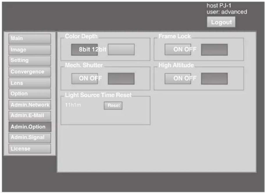
● indicates the factory default.
| Item Setting Value Description | ||
| Color Depth ● 8bit | 12bit | For configuring the color balance. |
| Frame Lock ● ON | OFF | For configuring the frame synchronization of each DVI input. |
| Mech. Shutter | ON● OFF | For configuring to ON/OFF the Mech. Shutter (model number: PK-VS4MS, optional, sold separately). Click “ON” to operate the Mecha Shutter. |
| High Altitude | ON● OFF | Configure to “ON” when using at high altitude (above 1,500 m). |
| Light Source Time Reset | - Resets the lifetime of the LD block. | |
(10) Admin.Signal Menu
This menu is for configuring settings such as display format, and for rewriting EDID.
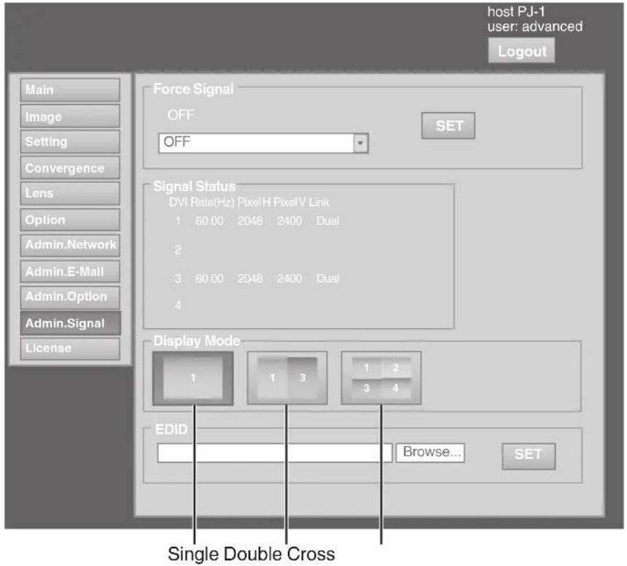
● indicates the factory default.
| Item Setting Value | Description | |
| Force Signal | ● OFF4096×2400, None, Dual4096×2400, None, Single2048×2400, 2Stripe, Dual2048×2400, 2Stripe, Single2048×1200, Cross, Dual2048×1200, Cross, Single1024×2400, 4Stripe, Dual1024×2400, 4Stripe, Single | For forcibly configuring the output signal. Make use of this setting when there is no display due to configuration changes at the input source. MEMOSome portions of the image may not be displayed and the image may become noisy.OFF :Turns off the display by force.4096×2400, :Displays a normal screen using dual link.None, Dual:Displays a normal screen using single link.4096×2400, :Displays a normal screen using single link.None, Single:Displays a 2 stripes screen using dual link.2048×2400, :Displays a 2 stripes screen using single link.2048×2400, :Displays a 2 stripes screen using single link.2Stripe, Single:Displays a cross screen using dual link.2048×1200, :Displays a cross screen using single link.Cross, Dual:Displays a 4 stripes screen using dual link.1024×2400, :Displays a 4 stripes screen using single link.4Stripe, Single:Displays a 4 stripes screen using single link.4Stripe, Single:Displays a 4 stripes screen using single link. |
● indicates the factory default.
| Item Setting Value Description | ||
| Signal StatusDVIRate(Hz)Pixel HPixel VLink | - | Displays information on the input signals. Same as “Signal Status” in the User Menu.DVI: Displays the DVI input terminal number.Rate(Hz): Displays the vertical frequency.Pixel H: Displays the horizontal resolution.Pixel V: Displays the vertical resolution.Link: Displays the link status of the DVI terminal.MEMOThis item is not displayed when there is no signal input.The text color of “Rate(Hz)” (vertical frequency) turns red in the case of interlaced signal. And the text turns white in the case of progressive signal. |
| Display Mode ● Single | DoubleCross | For specifying the display mode of the projection screen. Same configuration as “Display Mode” in the User Menu.Single: Displays input signals on a single screen.Double: Displays two different input signals on two screens.The left screen displays images of the [DVI 1] terminal, and the right screen displays images of the [DVI 3] terminal.Cross: Displays four different input signals on four screens.The top left screen displays images of the [DVI 1] terminal, the top right screen displays images of the [DVI 2] terminal, the bottom left screen displays images of the [DVI 3] terminal, while the bottom right screen displays images of the [DVI 4] terminal.MEMOPlease refer to “Connecting Video Signals of the Computer” for details. (P. 18 to 21) |
| EDID - For rewriting EDID. | Click the “Browse” button and select an EDID file.Click the “SET” button to start writing.Write “OK” will be displayed for each channel. “NG (number)” is displayed when writing fails.Error Code1: System error7: Unable to execute due to power off8: Unable to rewrite due to DVI cable connectionCAUTIONDo not turn off the power during rewrite.The EDID file capacity is within 256 byte.Rewriting to individual channel is not available.It is not possible to move on to other pages during rewrite.MEMOEDID: Extended Display Information DataA data to describe the specifications (resolution, model number, etc.) of the projector. The compatible transmitting device will output the optimum video signal based on this data. | |
Troubleshooting
Check the following points before sending this product for repair.
The following phenomena are not malfunctions.
If there is no abnormality on the screen when the phenomena below appear, they are not malfunctions.
- The top or front part as well as the rear of the projector unit is hot
• A creaking sound is heard from the projector
• Device noise is heard from the interior of the projector
• There is color bleeding on the screen
When the projector fails to run properly due to external noises, perform the following operations.
① Check to ensure that the power is shut down. Unplug the power cord, and insert again.
② Turn on the power of the projector
A sound maybe heard when the lamp burn out. However, this is not a hazard.
D-ILA devices are manufactured using extremely high-precision technology. However, some of the pixels may not lit up or remain permanently lit up.
| Symptom Probable Cause Corrective Action | Reference Page | ||
| Power is not supplied | • Is the power cord disconnected? | • Insert the power cord (plug) properly. P. 24 | |
| • Is the main power supply switched turned on? | • Turn on the main power supply switch of the projector unit. | P. 24 | |
| • Is the LD block in the cool down mode? | • Turn on the power again after the cool down mode ends. | P. 31 | |
| • Is the LD block protection function triggered? (This function is triggered when the power shuts down such as during power failures.) | • Wait until the temperature of the LD block drops. (Turn on the main power supply switch to run the fan to cool down the LD block.) Turn on the projector after about 10 seconds. | - | |
| Image is dark | • Is the LD block near exhaustion? | • Check the “Light Source Time” in the “Main” menu. When the LD block is near exhaustion, please consult your authorized dealer. | P. 36 |
| Projector works when the power is turned on, but stops abruptly after a few minutes | • Are the air inlets and vent holes blocked? | • Turn off the main power supply switch, and remove the blockage. After removing, turn on the power again. | P. 9 to 11, P. 32 |
| • Is the temperature of the room high? | • Set the temperature of the room or the surrounding temperature of this projector to an appropriate level. | P. 60 | |
| • Are the filters dirty? | • Clean the filters. P. 57 | ||
| Video image does not appear | • Is the lens cap removed? | • Remove the lens cap. P. 9 | |
| • Are devices properly connected? | • Connect the devices correctly. P. 19, 21 | ||
| • Is the power of the connected devices turned on? | • Turn on the power of the connected devices. | - | |
| • Are correctsignals being output from the connected devices? | • Configure the connected devices correctly. | - | |
| • Are the signals of the connected devices possible input signals? | • Check to ensure that they are possible input signals, and input compatible signals accordingly. | P. 18, 18 | |
| • Is the image temporarily hidden? | • Set “Hide” of the “Main” menu or “Image” menu to “OFF” to display the image. | P. 32, 36, 37 | |
| Video image is blur | • Is the projector out of focus? | • Adjust the focus using “Focus” of the “Lens” menu. | P. 31, 40 |
| • Is the projection distance too short or too long? | • Set it to a correct distance. P. 16, 17 | ||
| Image is unusually dark or bright | • Is the brightness level properly adjusted? | • Adjust accordingly using “Brightness” of the “Image” menu.• Adjust “Light Source Power” in the “Option” menu. | P. 37P. 41 |
| Coloring of the image is poor or distorted | • Is the contrast level properly adjusted? | • Adjust accordingly using “Contrast” of the “Image” menu. | P. 37 |
| • Are the signals of the connected devices possible input signals? | • Check to ensure that they are possible input signals, and input compatible signals accordingly. | P. 18, 20 | |
| • Is the input cable correctly connected? | • Connect the input cable correctly. P. 19, 21 | ||
| Projection position on the screen has shifted | • Has the setup position of the projector been shifted? | • Check the setup position of the projector. | - |
| Image disappears suddenly | • Are the video signals correctly input? | • Check the signals and connection. P. 18 | to 21 |
| Images do not appear on the two-screen mode display | • Are the [DVI 1] and [DVI 3] terminals connected for input? | • To display images in the two-screen mode, connect the [DVI 1] and [DVI 3] terminals. The left screen displays images of the [DVI 1] terminal, and the right screen displays images of the [DVI 3] terminal. | P. 20, 21 |
| Images do not appear immediately after power is turned on | • Formatting is in progress. | • Please wait for a maximum duration of 3 minutes for the formatting progress to end. | P. 29 |
| The screen does not darken immediately when the projection has ended | • The ending process is in progress. | • Please wait for a maximum duration of 2 minutes for the ending progress to complete after several hours of image projection. | P. 31 |
| The MENU is not displayed correctly | • It may be affected by your Web browser cache (temporary file storage). | • Delete all Web browser cache (temporary file storage). | - |
What to do when these messages are displayed
Messages are displayed when the LD block is exhausted or when a signal that is not usable is input.
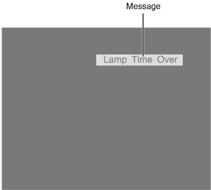
| Message Cause (Details) | |
| Lamp Time Over | Displayed when the lifetime of the LD block has exceeded 20,000 hours.The message is displayed for 3 minutes during each projection.→ For details, please consult your authorized dealer. |
| Out of Range | When there is input of video signals that cannot be used with this unit→ Input video signals that can be used. |
| No Input | When no device is connected to the input terminalWhen the input terminal is connected but there is no signal→ Input the video signals. |

MEMO
- The messages will not be displayed under factory default conditions.
- Set "Message Display" in the "Option" menu to "ON". (P. 41)
Warnings Using Indicators
The lifetime of the LD block and warning mode are indicated by the indicators.
For indicator displays during normal operation, refer to the note below.
| No. | Indicator | Description | ||
| STANDBY/ON LAMP WARNING | ||||
| 1 | *1 | Light On(Yellow) | - | When the lifetime of the LD block has exceeded 19,000 hours |
| 2 | When the lifetime of the LD block has exceeded 20,000 hours(Message display is also available. (P. 52)) | |||
| 3 | *2 | Blinking(Yellow) | Light On(Red) | When the LD block does not light up and projection fails |
| 4 When the LD block goes off during projection | ||||
| 5 | *2When the external temperature is unusually high, Light On(Red)Temperature is unusually high | When the ambient temperature of the LD block is high | ||
| 6 When the external temperature is unusually high | ||||
| 7 When the internal temperature is unusually high | ||||
| 8 When an abnormality has occurred in the cooling fan | ||||
| 9 When error occurs in the circuit operation | ||||
*1 The indicator lights up in red when in the standby mode, and in green when in the operating mode.
*2 The indicator lights up in red when in the warning mode, and blinks in red when in the cool down mode.
Measures when the warning mode appears
When the projector switches to the warning mode (Nos. 3 to 9), projection stops automatically, and the cooling fan runs for about 10 seconds.
After the cooling fan stops running, turn off the main power supply switch, and remove the power plug from the outlet.
Perform the following checks and take the corresponding measures.
| No. Check Measure | ||
| 3 | ·Check whether the projector has been subject to shock during operation. | ·Turn on the power again. |
| 4 | ||
| 5 | ·Check whether the air inlets are blocked by objects.·Check to ensure that the external temperature of the projector is normal. | ·Allow some time for the projector to cool down. |
| 6 | ||
| 7 | ||
| 8 | ||
| 9 | ||
If the warning indication is displayed again, turn off the main power supply switch after the cooling fan stops running.
Then pull out the power plug from the power outlet. Call your authorized dealer for repair.

MEMO
- Indicator display during normal condition.
| Indicator | Description | ||
| STANDBY/ON L | AMP WARNING | ||
| Light On (Red) - | - When in the standby mode. | ||
| Light On (Green) | - - When power is supplied (operating mode). | ||
| Blinking (Red) - | - When cooling down (cool down mode). (P. 31) | ||
| Blinking (Green) | - - When the projected image is temporarily hidden. (P. 32) | ||
Warning Status
The latest error code (Warning Status) appears in the "Main" menu when an abnormality occurs in the projector. Error details are as follows:
| Error Code Meaning | |
| 2 The lifetime of the LD | block has exceeded 20,000 hours. |
| 8 Abnormally high temperature in the projector. | |
| 9 Abnormally high temperature around the intake vent. | |
| A Abnormally high ambient temperature around the lamp. | |
| 15 The safety switch is activated. | |
| 30 Trouble with CPU circuit board. | |
| 31 Trouble with MAIN circuit board. | |
| 32 Trouble with DD-RB circuit board. | |
| 33 Trouble with DD-G circuit board. | |
| 34 Trouble with SUB CPU circuit board. | |
| 41 Cooling fan for the illumination system (PCS) has stopped. | |
| 42 Cooling fan for the circuit power has stopped. | |
| 43 Cooling fan for the DD circuit board has stopped. | |
| 44 Cooling fan for the MAIN circuit board has stopped. | |
| 46 Cooling fan for the PFC power has stopped. | |
| 48 Cooling fan for the DD RB has stopped. | |
| 4A Exhaust fan for the LD Driver has stopped. | |
| 4B Cooling fan for the LD Bank1 has stopped. | |
| 4C Cooling fan for the LD Bank2 has stopped. | |
| 50 Trouble with mechanical shutter. | |
RS-232C Interface
You can control this projector via a computer by connecting the computer to this unit using a RS-232C cross cable (D-sub 9 pins).
The commands to control this unit and the response data format against the received commands are explained here.
For details, please consult your authorized dealer.
Communication Specifications
Communication specifications for this unit are as follows:
| Transfer Rate 19200 bps | |
| Data Length 8 bit | |
| Parity None | |
| Stop Bit 1 bit | |
| Flow Control None |
Command Format
Command Data Format (PC→Projector)
When sending a control command to this unit, use the following data format:
![IDSP$PSPSPCCommand [ ] [ ] [ ] ParameterParameterHeader](/content/2026/05/976320/images/d25959753ed8bb4ae6ee36f6f463ab2ccb4a637314b10e96642ccb87e3cdacea.jpg)
Header : Designates the head of data and the data type.
“!” (21h): Assigns command to the projector (Command)
“?” (3Fh): Query to the projector (Asking command)
ID : “1”: Identification number of the projector (Factory setting is “1”)
SP : Designates the delimiter between ID and command, command and parameter, as well as parameter and parameter. (20h)
CR : Designates the terminal of the data. (0Dh)
* [ ] is not necessary for Asking command.
Response Data Format (Projector→PC)
Upon executing a control command, this unit sends back response data to the computer in this format.
![Header ID SP Normal Termination Status [ SP Parameter SP Parameter SP ... ] CR](/content/2026/05/976320/images/62d2bc1995cc45d28b6a3060b6f44362ed7e34bbde63789232031486e0208b86.jpg)
Header : Designates the head of the response data.
“@” (40h): Fetches data from the projector
ID : “1”: Identification number of the projector (Factory setting is “1”)
SP : Designates the delimiter between ID and normal termination status, normal termination status and parameter, as well as parameter and parameter. (20h)
Normal Termination : "0" (30h)
Status
CR : Designates the terminal of the data. (0Dh)
* [] is not applicable when sending commands to the projector.
Parameters used for the data format
The following 2 types of parameters are used for command and response data:
(1) ON/OFF (2) Special Parameter
Each parameter is as follows:
(1) ON/OFF
Shows the status (ON or OFF) of the unit, such as POWER and HIDE.
| Character Hex Meaning | ||
| 0 30 OFF | ||
| 1 31 ON |
(2) Special parameters
Operation mode parameters
| Character Hex Meaning | |
| 0 30 Standby state | |
| 1 31 Power ON state | |
| 2 32 Cooling state | |
| 3 33 Emergency cooling state | |
| 4 34 Emergency state |
DHCP client parameters
| Character Hex Meaning | ||
| 0 30 DHCP | ||
| 1 31 STATIC IP |
IP address parameters
Display the IP address using the dot (“.” (2HE)) delimiter.
Example: "192.168.0.10"
External control command table
| Function Command | Setting Asking Data Type | ||||||
| Power On ELSE Power | On ELSE ON | /OFF Special Parameter | |||||
| Power | U0F | ○ (OFF) | ○ (ON) | - | - | ○ | - |
| Hide U00 | ○ | - | ○ | - | ○ | - | |
| Operation Mode | UA0 | - | - | ○ | ○ | - | Standby... |
| DHCP Client | UD2 | ○ | ○ | ○ | ○ | - | DHCP... |
| IP Address | UD3 | ○ | ○ | ○ | ○ | - | 192.168. ... |
| Network Restart | UDC | ○ | ○ | ○ | ○ | - | “0” Fixed |

MEMO
- After configuring "DHCP Client" and "IP Address", execute "Network Restart".
Maintenance
Turn off the power of the projector unit, and unplug the power cord when cleaning or replacing the filter.
Cleaning and Replacing the Filter
Clean the filter regularly. If the filter is soiled, air intake efficiency may deteriorate, thus resulting in malfunction of the product.
Replace with a new one if the filter fails to remove dust thoroughly or if it is damaged. Failure to do so may cause dust to enter the projector and shadows to appear on the projected image.
If dirt has entered this product or if you need to purchase the filter, please consult the authorized dealer from which this product is purchased or any nearby JVC servicing center.
1
1
2123
1
CAUTION
Sponge
- Remove the four screws on the inner side (for fastening the filter cover).
Filter Cover
2
CAUTION
Sponge
- Remove the four screws on the inner side (for fastening the filter cover).
Filter Cover
3
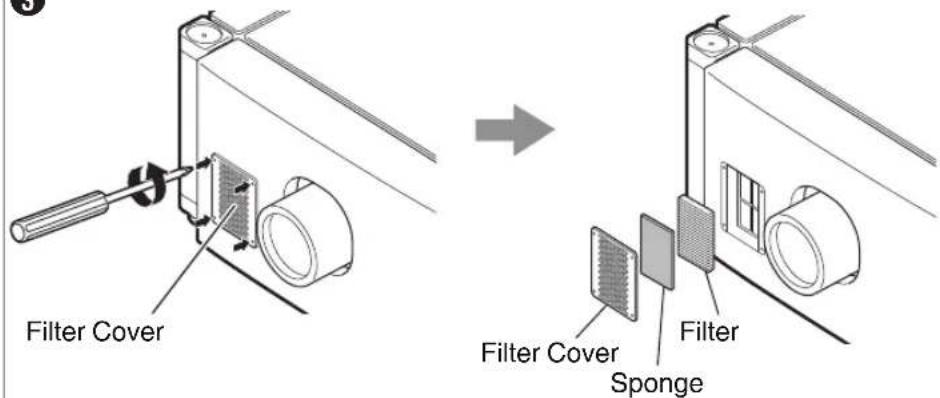

CAUTION
- Remove the four screws on the inner side (for fastening the filter cover).
1 Remove the filter cover
The filter is located at the front side of the projector unit.
2 Remove the sponge and filter
Hold the center of the filter using your fingers, and pull the filter toward you to remove it.
3 Clean the sponge and filter
Remove any dirt or dust using a vacuum cleaner.

CAUTION
- Do not clean using a flammable air duster. This may cause fire.
4 Mount the sponge and filter
Mount the filter and sponge to the projector using the reverse removed procedure.
Finally, check to ensure that the filter cover is firmly mounted.

MEMO
- Mount the filter correctly. Failure to do so may cause the projector to malfunction.
- The projector may stop operating if a damaged filter or filter panel is used. In this case, replace the filter or filter panel with a new one.
Routine Servicing
Clean dirt on the cabinet
Do this with a soft cloth. In case of heavy soiling, soak a cloth in neutral detergent diluted with water, wring dry and wipe, followed by wiping again using a dry cloth.
Pay attention to the following to prevent the cabinet from deteriorating in condition, getting damaged, or the paint from coming off.
- Do not wipe with a stiff cloth
- Do not wipe with force
- Do not wipe with thinner or benzene
- Do not spray volatile chemicals like insecticide
- Do not allow prolonged contact with rubber or plastic products
Remove dirt that is attached to the vent holes
Do this using a vacuum cleaner. Wipe using a cloth if a vacuum cleaner cannot be used. Leaving dust attached may prevent adjustment of the internal temperature and result in malfunction of the projector.
Clean dirt on the lens
Do this using commercial blowers or lens cleaning papers (for cleaning glasses and cameras).
Do not use fluid-type cleaning agents. This may lead to peeling of the surface coating film.
Lens surface is fragile. Avoid rubbing or knocking it.
Specifications
General
| Power supply AC 110 to 240 V, 50 Hz/60 Hz | |
| Power consumption 1250 W (Standby mode: 7 W) | |
| Current consumption 11.5 A max (AC 110 to 240 V) | |
| Calorific power 4500 kJ/h (1076 kcal/h) | |
| Air capacity | Intake: Approx. 6 m3/minExhaust: Approx. 6 m3/min |
| Allowable operating temperature range | 10°C to 35°C |
| Allowable operating humidity range 20% | to 80% (non-condensation) |
| Allowable storage temperature range | -5°C to 60°C |
| Installation height | Operation guarantee: 2000 m and belowPerformance guarantee: 1500 m and below |
| Dimensions | 660 mm x 342 mm x 934 mm (Width x Height x Depth)(Excluding lens and small protrusions) |
| Mass | DLA-VS4010: 73.5 kg (Excluding lens)DLA-VS4810: 74.5 kg (Excluding lens) |
Optical System
| Projection method D-ILA analog drive system × 3 | |
| D-ILA element *1*2 1.27" (4096×2400 pixels) × 3 pcs (total no. of pixels: 29,491,200 pixels) | |
| Projection Lens (optional) | GL-MS4015SZ(1.50:1 to 1.84:1 zoom lens)GL-MS4016SZ(1.50:1 to 1.84:1 zoom lens)GL-MS4021SZ(2.15:1 to 3.65:1 zoom lens)GL-MS4011S(1:1.1 Short focal length lens) |
| Light-source Lamp Laser diode | |
| Screen size | 80" to 300" (zoom lens)50" to 250" (short focal length lens) |
| Projection distance | Approx. 2.6 m to 12 m (zoom lens)Approx. 1.2 m to 6 m (short focal length lens) |
Terminal
| Video input | DVI-D (dual link) 24 pins(supports 12-bit extended input) × 4 (supports HDCP*3) |
| LAN RJ45 × 1 | |
| USB Type B (Slave) × 1 | |
| RS-232C D-sub 9 pins (male) × 3 | |
| e-shift Sync(DLA-VS4810 only) | BNC (male) × 1(3.3 V CMOS input level, high impedance) |
Optional Items
Projection lens
GL-MS4015SZ
• 1.50:1 to 1.84:1 1.22x zoom lens (80" to 300")
GL-MS4016SZ
• 1.50:1 to 1.84:1 1.22x zoom lens (50" to 210")
GL-MS4021SZ
• 2.15:1 to 3.65:1 1.69x zoom lens (80" to 300")
GL-MS4011S
• 1:1.1 short focal length lens (50" to 250")
Replacement filter/sponge (front)
LC43010-003A (Filter)
LC43030-003A (Sponge)
Replacement sponge (right/left side)
LC43030-002A
J3K-0072-00
*1 D-ILA is the abbreviation for Direct Drive Image Light Amplifier.
*2 D-ILA devices are manufactured using extremely high-precision technology with a pixel effectiveness of 99.99%. Only 0.01% or less of the pixels are either missing or would remain permanently lit.
*3 HDCP is the abbreviation for High-bandwidth Digital Content Protection system. Images from the DVI input terminal may not be displayed due to HDCP specification changes.
- The open source software is embedded in this product. For more information, please go to:
http://www3.jvckenwood.com/english/download/lnx/07jvc-pj/ - Design and specifications are subject to change without prior notice.
- Please note that some of the pictures and illustrations may have been abridged, enlarged or contextualized in order to aid comprehension. Images may differ from the actual product.
Pin Arrangement
- RS-232C Terminal
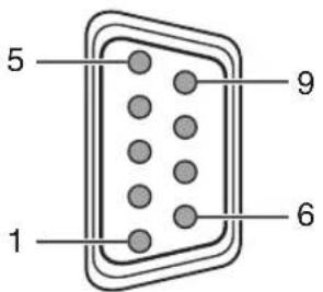
| Pin No. Signal | Action Signal Direction | ||
| 2 RxD Incoming Data | PC → This Projector | ||
| 3 TxD Outgoing Data | This Projector → PC | ||
| 5 GND Signal Ground - | |||
| 1, 4, 6-9 NC -- |
• DVI-D Terminal
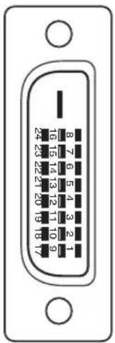
| Pin No. Signal Pin No. Signal | |||
| 1 TMDS Data 2- | 13 TMDS Data 3+ | ||
| 2 TMDS Data 2+ | 14 TMDS +5 V Power Supply | ||
| 3 TMDS Data 2/4 | Shield 15 Earth (+5 V) | ||
| 4 TMDS Data 4- | 16 Hot Plug Detection | ||
| 5 TMDS Data 4+ | 17 TMDS Data 0- | ||
| 6 DDC Clock | 18 TMDS Data 0+ | ||
| 7 DDC Data | 19 TMDS Data 0/5 Shield | ||
| 8 NC | 20 TMDS Data 5- | ||
| 9 TMDS Data 1- | 21 TMDS Data 5+ | ||
| 10 TMDS Data 1+ | 22 TMDS Clock Shield | ||
| 11 TMDS Data 1/3 Shield | 23 TMDS Clock + | ||
| 12 TMDS Data 3- | 24 TMDS Clock - | ||
TMDS = Transition Minimized Differential Signaling
DDC = Display Data Channel
Dimensional Outline Drawing
(Unit: mm)
Top Surface

Side
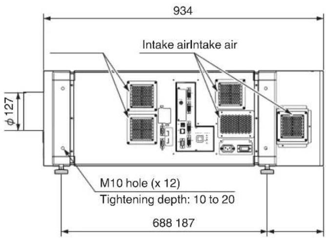
Front
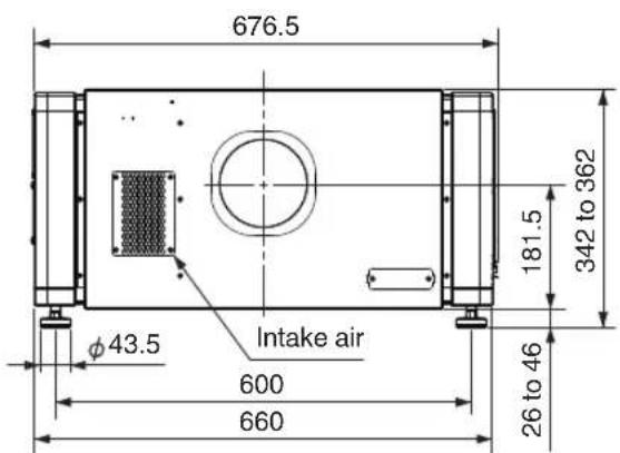
Rear Surface
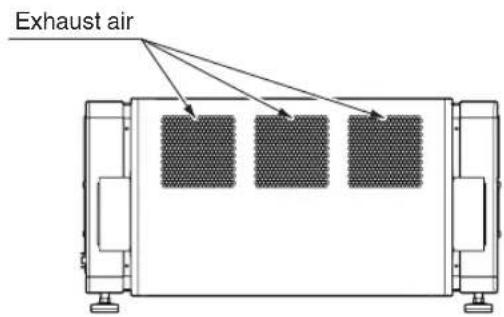

CAUTION
- Using screws with dimensions other than those specified in the above diagram may cause the projector to drop or malfunction.
DLA-VD54010 DLA-VS4810 DLA PROVECTOR
JVC
- D-ILA® BLU-Escent
- Safety Precautions
- IMPORTANT INFORMATION
- WARNING:
- CAUTION:
- FCC INFORMATION (U.S.A. only)
- NOTE:
- MACHINE NOISE INFORMATION (Germany only)
- About the installation place
- IMPORTANT SAFEGUARDS
- \* DO NOT allow any unqualified person to install the unit.
- POWER CONNECTION
- Do not cut off the main plug from this equipment.
- IMPORTANT (Europe only):
- EMC Supplement
- Dear Customer,
- For the customers In the U.S.A. and Canada
- CAUTION
- Location information of the labels
- WARNING
- Beam divergence angle from lens of this unit
- For the customers In other countries
- CLASS 1 LASER PRODUCT
- LASER CAUTION LABEL
- IEC62471-5
- RG LABEL
- ENGLISH
- Information for Users on Disposal of Old Equipment and Batteries
- [European Union only]
- FRANÇAIS
- Connection and Installation
- Network Settings
- Operation and Settings
- Others
- Accessories
- Content of this manual
- Names and Functions of Parts
- Front/Right, Left and Rear Side
- ① Air Inlet/Filter
- ② Lens Cap (included with the optional lens)
- ③ Projection Lens (optional)
- ④ Lens Mounting Bracket
- ⑤ Adjustable Feet (x4)
- ⑥ Air Inlet/Filter
- (Right Side: x5, Left Side: x3)
- ⑦ Vent Hole
- Right Side
- ⑧ [e-shift Sync] Terminal (DLA-VS4810 only)
- ⑨ [DVI 1 to 4] Terminal
- ⑩ [USB] Terminal
- ⑪ [LAN] Terminal
- ⑫ [RS-232C 1] Terminal
- ⑬ [RS-232C 2] Terminal
- ⑭ [RS-232C] Terminal
- ⑮ [OPERATE I/⏻] Button
- ⑯ [WARNING] Indicator
- ⑰ [LAMP] Indicator
- ⑱ [STANDBY/ON] Indicator
- ⑲ AC Power Input Terminal
- ⑳ Main Power Supply Switch
- MEMO
- Installation
- Optional Projection Lens
- Minimum Space Required
- Projector Installation Angle
- Adjusting the Inclination
- Installing the Projector and Screen
- When shift amount in the upward direction is +50 %
- When shift amount in the upward/downward direction is 0 %
- When shift amount in the downward direction is -50 %
- When shift amount in the right direction is +25 %
- When shift amount in the left/right direction is 0 %
- When shift amount in the left direction is -25 %
- Movable Range of Projected Image
- Lens Fixation Mechanism
- Overlaying projected images (when zoom lens is in use)
- Projecting images by stacking projectors
- Projecting images by arranging projectors side by side
- Screen Size and Projection Distance
- Connecting Video Signals of the Computer
- Connection During Single-Screen Mode Display
- Connection During Two-Screen/Four-Screen Mode Display
- Connection Using a LAN Cable
- Connection Example
- When assigning a static IP address
- When assigning IP address from the DHCP server
- Specifications of PC for Controlling this Projector
- Turning On the Main Power
- IP Address Settings
- Assigning a static IP address
- IP address setting at the computer
- Setting (Changing) the IP address of this projector
- Launch the Internet Explorer on the computer
- Check if the proxy has been set in the "LAN Setting" of the Internet Explorer
- Check if the "Active scripting" of the Internet Explorer is disabled
- 4
- Enter "advanced" in "Login Name"
- Click "LOGIN"
- 7
- 8
- Assigning IP Address from the DHCP Server
- After connecting, turn on the main power
- Set the "DHCP Client" setting of this projector to "DHCP"
- Connecting this projector and the computer using a USB cable
- Using the Mail Delivery Feature
- Connection Example (When DHCP Server is Used)
- Projecting Image
- Set this projector to the standby mode, and display the "Main" menu
- Click the "ON" button under the "Power" item of the "Main" menu to project the image
- Adjust the zoom ratio (screen size) (when zoom lens is in use)
- Adjust the position of the projection screen
- Adjust the focus
- Select a screen mode for projection
- Click the "OFF" button under the "Power" item of the "Main" menu to end the projection
- Cool down mode
- Turn the main power at the rear of the projector unit to off [O]
- Useful Features During Projection
- Hiding the projected image temporarily
- Displaying the Menu
- 1
- 2
- 3
- User Settings Menu
- Main Menu
- Image Menu
- Setting Menu
- Convergence Menu
- Lens Menu
- Option Menu
- Administrator Settings Menu
- Administrator Settings Menu Structure
- Admin.Network Menu
- Admin.E-mail Menu
- Admin.Option Menu
- Admin.Signal Menu
- Troubleshooting
- If there is no abnormality on the screen when the phenomena below appear, they are not malfunctions.
- When the projector fails to run properly due to external noises, perform the following operations.
- A sound maybe heard when the lamp burn out. However, this is not a hazard.
- D-ILA devices are manufactured using extremely high-precision technology. However, some of the pixels may not lit up or remain permanently lit up.
- What to do when these messages are displayed
- Warnings Using Indicators
- Measures when the warning mode appears
- Warning Status
- RS-232C Interface
- Communication Specifications
- Command Format
- Command Data Format (PC→Projector)
- Response Data Format (Projector→PC)
- Parameters used for the data format
- External control command table
- Maintenance
- Cleaning and Replacing the Filter
- Remove the filter cover
- Remove the sponge and filter
- Clean the sponge and filter
- Mount the sponge and filter
- Routine Servicing
- Clean dirt on the cabinet
- Remove dirt that is attached to the vent holes
- Clean dirt on the lens
- Specifications
- Optional Items
- Pin Arrangement
- Dimensional Outline Drawing
- JVC
Brand : JVC
Model : DLA-VS4010
Category : Video projector