Zpre3 - Hi-Fi System Parasound - Free user manual and instructions
Find the device manual for free Zpre3 Parasound in PDF.


| Product Type | Stereo Preamplifier |
| Dimensions (W x H x D) | 17 x 3.5 x 12 inches (432 x 89 x 305 mm) |
| Weight | 10 lb (4.5 kg) |
| Power Consumption (Standby) | < 15 W |
| Inputs | 4x RCA, 1x XLR (balanced), 1x IR control |
| Outputs | 2x RCA (main), 1x XLR (balanced), 1x trigger out |
| Frequency Response | 20 Hz – 20 kHz (±0.5 dB) |
| Total Harmonic Distortion (THD) | < 0.01% |
| Signal-to-Noise Ratio | > 100 dB (A-weighted) |
| Remote Control | Included (IR) |
| Trigger Input/Output | 12 V (3.5 mm mini-jack) |
| Material Chassis | Brushed aluminum front panel, steel chassis |
| Power Supply | 120 V AC, 60 Hz (US version); other voltages for export |
| Operating Temperature | 32°F to 104°F (0°C to 40°C) |
| Maintenance | Clean exterior with a soft, dry cloth; do not use liquids or solvents |
| Safety Warnings | Disconnect power before cleaning; do not expose to moisture; use only grounded outlets |
| Repair and Servicing | Contact qualified service personnel; no user-serviceable parts inside |
| Spare Parts Availability | Contact Parasound or authorized dealers for parts |
| Warranty | 5 years parts and labor (USA) |
Frequently Asked Questions - Zpre3 Parasound
User questions about Zpre3 Parasound
0 question about this device. Answer the ones you know or ask your own.
Ask a new question about this device
Download the instructions for your Hi-Fi System in PDF format for free! Find your manual Zpre3 - Parasound and take your electronic device back in hand. On this page are published all the documents necessary for the use of your device. Zpre3 by Parasound.
USER MANUAL Zpre3 Parasound
Important Safety Instructions
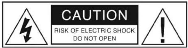
The lightning flash with the arrowhead symbol within an equilateral triangle is intended to alert the user to the presence of "dangerous voltage" inside the product that may constitute a risk of electric shock.
The exclamation point within an equilateral triangle is intended to alert the user to the presence of important operating and maintenance instructions in the literature accompanying the product.
TO REDUCE THE RISK OF ELECTRIC SHOCK, DO NOT REMOVE COVER. NO USER-SERVICEABLE PARTS INSIDE. REFER SERVICING TO QUALIFIED SERVICE PERSONNEL
- Read Instructions — Read all the safety and operating instructions before operating this product.
- Retain Instructions — Retain safety and operating instructions for future reference.
- Heed Warnings — Adhere to all warnings on the product and in the operating instructions.
- Follow Instructions — Follow all operating and use instructions.
- Cleaning — Unplug this product from the wall outlet before cleaning. Use a damp cloth for cleaning. Clean the outside of the product only.
- Attachments — Do not use attachments that are not recommended by the product manufacturer; they may be hazardous.
- Water and Moisture — Do not use this product near water.
- Accessories — Do not place this product on an unstable cart or stand. The product may fall, causing bodily injury and damage to the product. A product and cart combination should be moved with care. Quick stops, excessive force, and uneven surfaces may cause the product and cart to overturn.
- Ventilation — Slots and openings in the cabinet are provided for ventilation to ensure reliable operation of the product and to protect it from overheating. These openings must not be blocked or covered. This product should not be placed in a built-in installation such as a bookcase or rack unless proper ventilation is provided.
- Power Sources — Operate this product only from the type of power source indicated on the label. If you are not sure of the type of power supply to your home, consult your dealer or local power company. This product is equipped with a three-prong grounding plug. This plug will only fit into a grounding power outlet. If you are unable to insert the plug into the outlet, contact your electrician to replace your obsolete outlet. Do not defeat the safety purpose of the grounding plug.
- Power Cord Protection — Power supply cords should be routed so that they are not likely to be walked on or pinched by items placed upon or against them.
- Lightning — Unplug the unit from the wall outlet for added protection during a lightning storm and when it is left unattended and unused for long periods of time. This will prevent damage to the product due to lightning and power line surges.
- Overloading — Do not overload wall outlets or extension cords. This can result in a fire or electric shock.
- Inserting Objects into Unit — Never push objects of any kind into this product through any openings; they may touch dangerous voltage points or short out parts that could result in fire or electric shock.
- Servicing — Do not attempt to repair or service this product yourself. Opening or removing covers may expose you to dangerous voltage and other hazards. Refer all servicing to qualified service personnel.
- Damage Requiring Service — Unplug this product from the wall outlet and refer servicing to qualified service personnel under the following conditions: a) If the power-supply cord or plug is damaged. b) If liquid has been spilled into the product. c) If the product has been exposed to rain or water. d) If the product does not operate normally by following the operating instructions. e) If the product has been dropped or damaged in any way. f) If the product exhibits a distinct change in performance.
- Replacement Parts — When replacement parts are required, be sure the service technician has used replacement parts specified by the manufacturer. Unauthorized substitutions may result in fire, electric shock, and other hazards.
- Safety Check — Upon completion of any service or repairs to this product, ask the service technician to perform safety checks to determine that the product is in proper operating condition.
- Wall or Ceiling Mounting — Mount the product to a wall or ceiling only as recommended.
- Heat — The product should be situated away from heat sources such as radiators, heat registers, stoves, and other products (including amplifiers) that produce heat.
THE FOLLOWING PRECAUTIONS AND SAFETY INSTRUCTIONS ARE REQUIREMENTS OF UL AND CSA SAFETY REGULATIONS
Warning: To reduce the risk of fire or electric shock, do not expose this unit to rain or moisture.
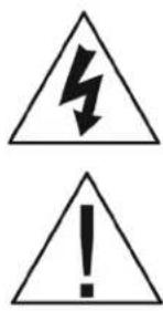
The graphic symbol of a lightning flash with an arrow point within a triangle signifies that there is dangerous voltage within the unit and it poses a hazard to anyone removing the cover to gain access to the interior of the unit. Only qualified service personnel should make any such attempt.
The graphic symbol of an exclamation point within an equilateral triangle warns a user of the device that it is necessary to refer to the instruction manual and its warnings for proper operation of the unit.
Do not place this unit on an unstable cart, stand, tripod, bracket, or table. The unit may fall, causing serious injury to a child or adult, and serious damage to the unit. Use only with a cart, stand, tripod, bracket, or table recommended by the manufacturer or sold with the unit. Any mounting of the device should follow the manufacturer's instructions, and should use a mounting accessory recommended by the manufacturer.
Read all the safety and operating instructions before connecting or using this unit.
Retain this notice and the owner's manual for future reference.
All warnings on the unit and in its operating instructions should be adhered to.
All operating and use instructions should be followed.
Do not use this unit near water. For example, near a bathtub, washbowl, kitchen sink, laundry tub, in a wet basement, or near a swimming pool.
The unit should be installed so that its location or position does not interfere with its proper ventilation. For example, it should not be situated on a bed, sofa, rug, or similar surface that may block the ventilation openings; or placed in a built-in installation, such as bookcase or cabinet, that may impede the flow of air through its ventilation openings.
The unit should be situated away from heat sources such as radiators, heat registers, stoves, or other devices (including amplifiers) that produce heat.
The unit should be connected to a power supply outlet only of the voltage and frequency marked on its rear panel.
The power supply cord should be routed so that it is not likely to be walked on or pinched, especially near the plug, convenience receptacles, or where the cord exits from the unit.
Clean unit only as recommended in its instruction manual.
The power supply cord of the unit should be unplugged from the wall outlet when it is to be unused for a long period of time.
Care should be taken so that objects do not fall, and liquids are not spilled, into the enclosure through any openings.
This unit should be serviced by qualified service personnel when:
A. The power cord or the plug has been damaged; or
B. Objects have fallen, or liquid has been spilled, into the unit; or
C. The unit has been exposed to rain, or liquids of any kind; or
D. The unit does not appear to operate normally, or exhibits a marked change in performance; or
E. The device has been dropped, or the enclosure damaged.
DO NOT ATTEMPT SERVICING OF THIS UNIT YOURSELF. REFER SERVICING TO QUALIFIED SERVICE PERSONNEL.
ATTENTION
POUR PREVENIR LES CHOCS ELECTRIQUES NE PAS UTILISER CETTE FICHE POLARISEE AVEC UN PROLONGATEUR, UNE PRISE CE COURANT OU UNE AUTRE SORTIE CE COURANT, SAUF SI LES LAMES PEUVENT ETRE INSEREES A FOND SANS EN LAISSER AUCUNE PARTIE A DECOUVERT.
CAUTION
TO PREVENT ELECTRIC SHOCK DO NOT USE THIS POLARIZED PLUG WITH AN EXTENSION CORD, RECEPTACLE OR OTHER OUTLET UNLESS THE BLADES CAN BE FULLY INSERTED TO PREVENT BLADE EXPOSURE.
CAUTION POWER LINES
Any outdoor antenna must be located away from all power lines.
OUTDOOR ANTENNA GROUNDING
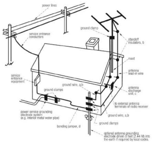
If an outside antenna is connected to your tuner or tuner/preamplifier, be sure the antenna system is grounded so as to provide some protection against voltage surges and built-up static charges. Section 810 of the National Electrical Code, ANSI/NFPA No. 701984, provides information with respect to proper grounding of the mast and supporting structure, grounding of the lead-in wire to an antenna discharge unit, size of grounding conductors, location of antenna discharge unit, connection to grounding electrodes, and requirements for the grounding electrode.
a. Use No.10 AWG (5.3 mm²) copper, No.8 AWG (8.4 mm²) aluminum, No.17 AWG (1.0 mm²) copper clad steel or bronze wire, or larger, as a ground wire.
b. Secure antenna lead-in and ground wires to house with stand-off insulators spaced from 46 feet (1.221.83 m) apart.
c. Mount antenna discharge unit as close as possible to where lead-in enters house.
d. Use jumper wire not smaller than No.6 AWG (13.3 mm²) copper, or the equivalent, when a separate antenna grounding electrode is used. See NEC Section 810-21 (j).
EXAMPLE OF ANTENNA GROUNDING AS PER NATIONAL ELECTRICAL CODE INSTRUCTIONS CONTAINED IN ARTICLE 810. RADIO AND TELEVISION EQUIPMENT.
NOTE TO CATV SYSTEM INSTALLER
This reminder is provided to call the CATV system installer's attention to Article 82022 of the National Electrical Code that provides guidelines for proper grounding and, in particular, specifies that the cable ground shall be connected to the grounding system of the building, as close to the point of cable entry as practical.
Congratulations on your purchase of this precision audio product and thank you for selecting Parasound. We are proud to offer you this versatile preamplifier, knowing that it will bring you many years of enjoyment and dependable operation. Please take a few moments to read the following instructions so you can enjoy all the benefits of your new Zpre3's advanced performance capabilities.
You can find details of the Zpre3's specifications and advanced technology at www.parasound.com.
Enjoy.
The Parasound Staff www.parasound.com
Keep your Purchase Receipt/Dealer Invoice for future reference Keep the carton in the event it is needed in the future
Record the 5 digit serial number located on the bottom side of your Zpre3 in the space below. Also note your Parasound dealer's name and telephone number. Your purchase receipt-dealer invoice is required to determine if your Zpre3 is eligible for Parasound warranty service. We recommend that you make an extra copy of your original purchase receipt-dealer invoice and store it inside the Zpre3's carton. If the Zpre3 should require warranty repair you will need its original carton and foam packing inserts to ship it.
Please do not throw away the carton or foam packing inserts.
Parasound Zpre3 Serial # ____
Parasound Dealer: ____
Parasound Dealer Phone Number: ____
Date of Purchase: ____
Important Warranty information
There is no Parasound warranty for this unit if it was not purchased from an Authorized Parasound Dealer. Investigate warranty coverage statements made by unauthorized dealers very carefully, as Parasound will not provide service under our warranty and you will need to depend entirely upon the unauthorized dealer for warranty service. A list of Authorized Parasound Dealers and detailed warranty information is available at www.parasound.com or you can call Parasound at (415) 397-7100 between 8:30 am and 4 pm Pacific time.
A missing or altered serial number could indicate that this unit was re-sold by an unauthorized dealer or is stolen merchandise. If this unit is missing its serial number or the serial number has been altered, you should return it to your dealer immediately for a full refund.
Table of Contents
Introduction 4
Placement and Ventilation Guidelines 6
Rear Panel Layout and Connections 7
Audio Input Connections
Inputs 1-4 7
Front Panel AUX Input 7
Bypass Input 7
Audio Output Connections
Fixed & Variable Stereo Outputs 8
Fixed & Variable Mono Outputs. 8
Connecting a Subwoofer....8
Headphone Jack 8
12 Volt, IR and RS-232 Connections 9
Front Panel Display and Controls
Multifunction Volume / Select Knob 9
Selecting Inputs 9
Bass, Treble and Balance Adjustments 9
Remote Control 10
Renaming Inputs 11
Special Volume Features
Setting the Turn On Volume 12
Favorite Volume Memory (Mem button) 12
Troubleshooting 13
If You Require Assistance or Warranty Repair 14
Specifications and Details 15
Unpacking your Zpre3 & Placement Guidelines
Unpacking Your Zpre3
Carefully remove your Zpre3 from its shipping carton and locate its AC power cord and these included accessories:
☐ One 12V trigger cable with mono 3.5mm mini plugs at both ends.
One 12V trigger cable with a mono 3.5mm plug on one end and a 2.5mm plug on the other end.
Remote control and two AAA batteries.
While you are unpacking your Zpre3, inspect it thoroughly for evidence of possible shipping damage and tell your Parasound dealer immediately if you find any. If possible, save and store both the inner and outer cartons and—most especially—the foam packing inserts, to protect the Zpre3 if you move it or have to ship it. This would be a good time to make a copy of your sales receipt for storage with the Zpre3's original packing.
Placement Guidelines
Install your Zpre3 away from heat sources such as heating ducts, radiators, or other heat-producing components. Always position the Zpre3 horizontally. Observe the following ventilation guidelines when installing the Zpre3 in an equipment rack or any other enclosed space:
You should avoid install the Zpre3 in an unventilated equipment cabinet or small compartment because hot air will not exhaust adequately to prevent overheating. Even a small cabinet or enclosure whose front and back sides are open doesn't guarantee that air will circulate adequately pockets of intense heat can still develop around any heat-producing equipment. Allow a few inches of empty space on each side and above the unit and try to avoid crowding or stacking the Zpre3 tightly between other components.
If you are installing the Zpre3 yourself, use input and output cables that are long enough to leave at least two feet of slack; that will enable you to pull the Zpre3 out of a cabinet to check or to change connections without inadvertently disconnecting cables.
Rack Mounting Your Zpre3
A rack mount adapter model "ZRK" is available for purchase separately. This kit allows two half width ZoneMaster or Z Custom units to be installed in a rack side by side. Included in the kit is also a panel extender to rack mount a single Zpre3.
AC Line Power Cord
Connect your sources and preamplifier before you plug in the AC cord. The power cord supplied with your Zpre3 is an IEC type 18AWG AC cord. The AC ground potential can vary between your AC outlets and the result can be an audible 60Hz (or 50Hz) hum heard in your speakers. To help avoid this problem plug your Zpre3 into the same AC wall outlet, power strip or line conditioner as you have plugged in your power amplifier and other audio components. The power cord might be different for units sold in other regions of the world.
Rear Panel Layout and Connections
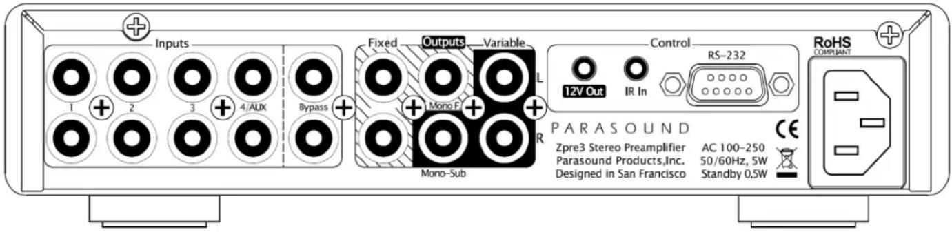
Always turn off or disconnect the AC cord to your Zpre3 before plugging in or unplugging any connections. Inserting or removing an interconnect cable's plug while this unit or the power amp is turned on can result in a burst of sound that can damage your loudspeakers. Make sure there is no strain or tension on any input cables, speaker wires, DC trigger wires or the AC cord that could cause them to pull loose.
Audio Input Connections
Inputs 1 - 4
Inputs 1, 2, 3 and 4 on the rear panel all have the same input sensitivity and input impedance and they are compatible with any typical analog line level source.
Input 4/Aux
Input 4 is shared with the Aux input jack on the front panel. The front panel Aux Input has priority over Input 4 on the rear panel. When a plug is inserted into the front panel Aux jack the rear panel Input 4 is automatically disconnected and you will not hear the source connected to the Input 4 jacks. When the plug is removed from the front Aux jack the rear panel Input 4 will be reconnected. As long as a cable is plugged into the front panel Aux jack you will not be able to hear the source connected to Input 4 on the rear panel.
Front Panel Aux Input
For your convenience the Zpre3 provides an input jack on the front panel for a mobile phone or portable music player. Connect any standard 3.5 mm stereo aux cable to connect your portable player or phone's headphone jack and the Aux Input jack. The Aux Input has an additional gain stage that boosts the input signal by 12dB so that the volume level remains consistent with your other audio sources. For the best result set your portable player or phone's volume to at least 75% of its maximum level. If you connect a component other than a portable music player or phone to the Aux Input jack, the volume level will probably be too high and likely distorted.
AUX & Input 4 Priority: When you insert a 3.5mm stereo plug into the front panel Aux jack the rear panel Input 4 will immediately be disconnected. If you are listening to Input 4 the sound will stop. When you remove the 3.5mm cable from the Aux jack, Input 4 will immediately be reconnected.
Bypass Input
The Bypass input jacks are used to integrate the Zpre3 with additional stereo sources that have their own volume control. The most common example would be a music streaming device such as a Sonos ^® Connect ^® or Apple ^® Airport Express ^® . Other sources might include a separate AV receiver or pre-amp, additional house audio controllers or Bluetooth adapters. A source connected to the Bypass input will be audible when the Zpre3 is turned off or by selecting the Bypass input when the unit is turned on.
Bypass info continued on next page...
Bypass Input (Continued)
The Bypass input passing the incoming left and right channels directly through to the Left and Right Variable Output jacks. None of the Zpre3 circuits or controls has any effect on the bypassed signal and the volume level from the source component pass through unchanged. The Bypass input is automatically selected and connected to the Left and Right Variable output jacks when the Zpre3 is turned off. Please note the following operational functions of the Bypass input:
Adjusting the Zpre3 volume will not change the volume level for the Bypass input.
The Bass and Treble tone controls will not function therefore frequency response is flat, regardless of how these controls are set.
The Left/Right Balance control does not function; channel balance is equal, regardless of how this control is set.
Only the L and R Variable output jacks are active.
There is no output from the Variable Mono (subwoofer) output jack.
There is no output from the Fixed L, R or Mono output jacks.
There is no sound from the headphone jack.
The Mute button does not function.
CAUTION: Do not connect any source component such as a CD player, Blu-ray player or tuner directly to the Bypass Input jacks. Since there is no volume control with the Bypass input the full voltage output from the source will go directly to the Zpre3's Variable output jacks and thus to the power amplifier. The sound level could be extremely high and could damage your speakers.
Audio Output Connections
L & R (Stereo) Variable Outputs
These outputs connect directly to a power amplifier. They are called "variable" because their output level is determined by the volume control setting.
Mono-Sub (Subwoofer) Variable Output
This is a summed L+R full range signal with a variable output. The most common use of this jack would be for a subwoofer. Since this output is full range, you will need to use the low
pass crossover built into your subwoofer. This mono output may also be used for listening areas where a mono speaker is more appropriate such as a bathroom, hallway or outdoors.
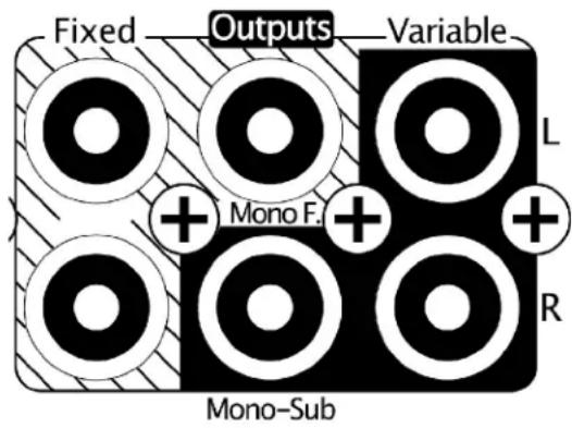
L & R (Stereo) Fixed Outputs
These outputs are not affected by the setting of the volume control. The bass, treble and balance controls also do not affect this output. These could be used in conjunction with passive (in-wall) volume controls or for making recordings.
Mono F. (Fixed) Output
This is a summed L+R full range "fixed" output. This output is not affected by the setting of the volume, bass, treble or balanced controls. The most common use would be with passive (in-wall) volume controls and mono speaker(s).
Headphone Jack
The headphone jack on the front panel accepts a 1/8" (3.5 mm) stereo plug. The variable outputs are automatically muted when you plug in headphones. The Fixed outputs are not muted when headphones are plugged in.
12 Volt, IR and RS-232 Connections
12 Volt Output Jack
The 12V Out is used to turn a power amp or other accessories on and off automatically. If your power amplifier is equipped with a 12 volt trigger input, connect the included trigger cable between the Zpre3's 12V Out jack and the amplifier's 12 volt trigger input. When the Zpre3 is powered on, 12 volts will be present at the 12V output jack and your amp will turn on automatically. When the Zpre3 is powered off your amp will automatically turn off.
IR Input Jack
Your Zpre3 is compatible with most infrared repeater systems for operation from another room or when the Zpre3 is installed in a cabinet where its remote handset commands cannot reach its front panel IR receiver. The IR Input connector is a standard 1/8" (3.5 mm) mono "mini" jack. The center conductor (plug tip) is for the signal and the outer conductor (plug sleeve) is for ground. Your Authorized Parasound dealer or custom installer can recommend a compatible IR repeater system.
RS-232 Control Port
This DB9 serial port permits the Zpre3 to be controlled by home automation and control systems such as Crestron®, AMX®, Control4®, Savant® and Elan®. When the Zpre3 is connected to such a device, it can be controlled from keypads or touch-screen panels throughout your house. The RS-232 port is a 2-way signal for both control and status feedback. The capabilities of such connections, and the programming and interfacing needed will depend on the automation system you select. Consult your Parasound dealer or custom installer for more information regarding interfacing an external control system to your Zpre3. The complete Zpre3 RS-232 protocol can be found at: www.parasound.com.
Front Panel Display and Controls
Multifunction Volume / Select Knob
The knob on the front panel controls several different functions. The default function of the knob is volume control. Each time the knob is pressed inward the function that the knob controls will change. The knob functions rotate through in this order with each press:

flowchart
graph LR
    A["Volume"] --> B["Input"]
    B --> C["Bass"]
    C --> D["Treble"]
    D --> E["Balance"]
Volume
Rotating the knob left or right increases or decreases the volume level. The range is from 0 to 100. A setting of 100 represents a total gain of 12dB. A setting of 88 is unity gain where the output voltage is the same as the input voltage.
Input
After pressing the knob a single time, rotating it will cycle through all of the inputs. Stop on the input you wish to hear then press the knob in to select that input or simply wait 5 seconds and the input will be selected automatically.
Bass/Treble
After pressing the knob twice, rotate it to increase or decrease the bass. Press the knob again and rotate it to control treble. Bass and Treble are adjusted in 1dB increments over a +/- 8dB range.
Balance
Press the knob again and rotate it to shift the balance to the left or right. This can be helpful to compensate for speaker placement or room acoustics. The maximum adjustment is 15dB.
Remote Control
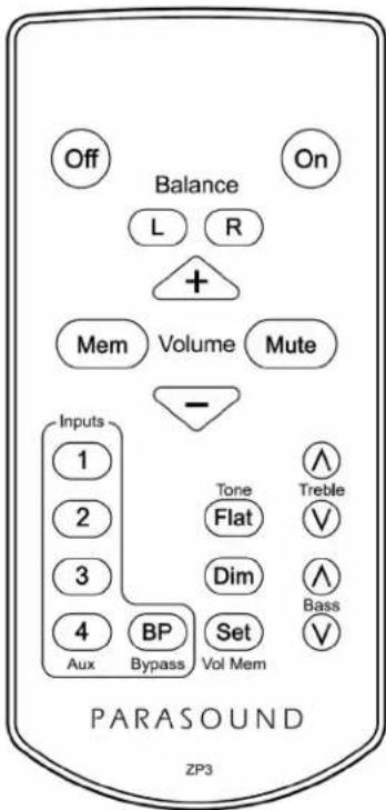
Off & On
These buttons turn power on and off.
Balance L & R
Use these buttons to shift the balance to the left or right. This can be helpful to compensate for speaker placement or room acoustics. The maximum adjustment is 15dB.
Volume + & -
The + and - buttons increase and decrease the volume level.
Mute
Press to mute the audio. Pressing a second time will unmute the audio. The mute is also turned off automatically if you increase or decrease the volume or if you power the unit off and back on again.
Mem
This button recalls the volume setting you have memorized. This is a convenient way to jump to your favorite volume setting. See page 12 for instructions on how to set the Mem volume level.
Inputs 1-4/Aux
These buttons select the input you wish to hear.
BP (Bypass)
This button selects the Bypass input. The Bypass input is also automatically selected when the unit is turned off. See page 7 for more information.
Tone Flat
This button resets the Treble and Bass settings to zero (flat).
Bass & Treble
Raise or lower the amount of bass and treble by using these buttons.
Dim
Press this button to select one of the display's two brightness levels.
Set / Vol Mem
The Set button is used in conjunction with other buttons for setting up some features. These features include setting the turn on volume, Mem (favorite) volume and renaming the inputs. See page 12 for instructions on how to use these features.
Renaming Inputs
The factory default input names are "Input 1", "Input 2", "Input 3", "Input 4/Aux" and "Bypass". To make it easier to remember which source is connected to what input number you may wish to rename the inputs. Any of the inputs can be renamed to be one of the names in the following list.
| CD PLAYER | PHONE | LAPTOP |
| DVD | MP3 PLAYER | TABLET |
| BLU-RAY | BLUETOOTH | NETWORK |
| SACD | GAME | SERVER |
| DAC | CABLE | INTERNET |
| DISC | SAT | WIRELESS |
| TUNER | TV | |
| VINYL | VIDEO | |
| PHONO | PC | |
| TAPE | MAC |
Renaming Procedure:
1) Select the input number you wish to change.
2) Press the "Set" button.
3) Press the "L" or "R" balance buttons to cycle through the available names.
4) When you have found the name you want to use press "Set" again to memorize.
Repeat steps 1 through 4 for the other inputs.
Turn On Volume & Favorite Volume Settings
Turn On Volume
You may wish your Zpre3 to come on to the same volume setting every time it is turned on. This can be particularly useful if you sometimes listen at high volume levels and you want to avoid a blast of sound the next time you turn it on. Or you may have a preferred listening level. To set the Turn On volume setting follow these steps:
Setting the Turn On Volume:
1) Adjust the volume to the level you wish to program
2) Press the "Set" button
3) Press the "On" button
Now every time the Zpre3 is turned on the volume will automatically be set to the level you have programmed.
Cancel the Turn On Volume Feature (Use Last Volume)
You may wish to cancel the "Turn On Volume" feature. In this case, when the Zpre3 turns on the volume will be at the same level as when it was turned off. Follow these steps to have the Zpre3 turn on to the level it was last used at:
Cancel the Turn On Volume feature:
1) Press the "Set" button
2) Press the "Off" button
Now when the Zpre3 turns on the volume will be set to where it was last used.
Memorizing a Favorite Volume Level (Mem button)
For your convenience, you can memorize your favorite listening level. Once memorized you can easily jump to this listening level by pressing the "Mem" button on the remote control.
Memorizing a favorite volume level:
1) Adjust the volume to the level you wish to be memorized
2) Press the "Set" button
3) Press the "Mem" button
You can now jump to your favorite listening level by pressing the Mem button at any time. This is different than the "Turn On Volume" you may have already set.
Troubleshooting
When the unit turns on the volume always jumps to the same setting
- The "Turn On Volume" feature has been activated. See page 12 on instructions on how to turn off this feature. This can only be done using the remote control.
There is no sound from input 4
- Input 4 is shared with the front panel Aux Input. When a plug is inserted into the front panel Aux jack the rear panel Input 4 is disconnected. To use both the Input 4 and the Aux Input you must unplug the front panel Aux cable when not using it.
When I use the Bypass Input the sound is very loud and cannot be turned down
- The Bypass input should never be connected directly to a source component (CD, DVD, Tape deck, etc.). The source connected must have its own volume control and that will be used to adjust the volume level. See page 7 for more information.
The sound is distorted and weak
- Make sure the gain of the power amp is not set too low.
- Are you trying to use P 5 with a turntable? Make sure you have set the phono selector switch to the correct cartridge type. Is the turntable's tracking force adjusted correctly for its cartridge?
- Make sure the stereo power amp's stereo/mono switch is set to stereo.
I can hear a hum or buzzing noise from my speakers
- Cable TV is the most common source of hum or buzzing noise in a system. If you have a cable TV box connected to your audio system temporarily remove the incoming cable signal from the Cable TV box. If the hum goes away the problem is with the cable TV ground. You will need a cable TV ground Loop Isolator which is an inexpensive device that attaches between your incoming cable and the Cable TV box.
- Light dimmers can cause noise in your audio system. Try turning lights that are controlled by dimmers all the way off. If the hum goes away the problem is electrical noise the dimmers introduce into your home's AC power.
- Ground loops are also a common cause of hum and buzzing noise. Finding a ground loop is a process of elimination. Unplug your source components one at a time. When the hum goes away you've identified the source of the ground loop. You might be able to stop the hum by attaching a wire from the chassis of the offending component to the chassis or ground screw of your preamplifier.
Maintaining Your Zpre3
Your Zpre3 requires no periodic maintenance and has no user serviceable parts inside. To avoid risk of electric shock do not remove the top cover. To keep it clean use only a soft cloth moistened with a few drops of clear water or window cleaner. Never use any solvents or abrasives.
Are You Having Difficulty?
Warranty Repair
Call your Parasound dealer first. If the dealer can't help you with your problem we encourage you to call Parasound's Technical Service Department at 415-397-7100, Monday - Friday, 8am
- 4pm Pacific time. We can suggest other diagnostic tests you can easily perform.
If we determine that your Zpre3 should be returned to Parasound or an Authorized
Parasound Warranty Center for inspection and possible servicing, we will provide the location of a warranty center near you or shipping instructions for the unit's return to Parasound.
Read your accompanying Parasound Limited Warranty carefully to understand the applicable rights and limitations. This section provides instructions for obtaining repairs, both for units covered under the Parasound Limited Warranty and for units or situations which are outside the Warranty.
Unit is not eligible for repair under the terms of the Parasound warranty if:
- Unit was not purchased from a Parasound Authorized Dealer.
- You do not have the original bill of sale or sales receipt from a Parasound Authorized Dealer.
- You are not the original owner. The Parasound warranty is not transferable.
- Unit's serial number was removed, modified, or defaced.
- Unit shows evidence of abuse and/or misuse.
- Unit was modified in any way.
- A prior repair was attempted by an unauthorized repair station.
Before You Return Any Unit to Parasound for Service
Before you send your unit to Parasound, you will need to obtain a specific Return Authorization (RA) number and shipping instructions from Parasound's Technical Department. The RA number must be clearly marked on the outer carton. Use the original factory packing materials and arrange adequate insurance to cover its replacement value. You must include a copy of your purchase receipt, since this document establishes the validity of this unit's warranty. Warranty repairs are only performed by Parasound or Parasound Authorized warranty centers when your purchase receipt is from a Parasound Authorized Dealer or Parasound Authorized Reseller.
Do not ship to Parasound by the USPS (US Postal Service) - we will not accept delivery. We will also refuse delivery of units whose cartons show evidence of damage caused by inadequate packing.
Specifications and Details
Frequency Response:
10Hz - 40kHz, +0 / -0.5dB
Total Harmonic Distortion: (20Hz - 20kHz)
< 0.015%
Interchannel Crosstalk:
62dB at 20kHz
Input Sensitivity:
250mv = 1V output
Total gain = 12dB (volume set to 100)
Unity Gain = Volume set to 88
Maximum output = 3.5V
Input Impedance:
24k Ohms
Output Impedance:
470 Ohms
S/N Ratio:
100dB, input shorted, IHF A-weighted
90dB, input shorted, unweighted
DC Trigger Output:
12Vdc, 50ma
AC Power Requirement:
5 Watts powered on
0.5 Watts in standby
100-250 VAC 50/60 Hz
Dimensions:
Width: 8.5" (220 mm)
Depth: 10" (254 mm)
Depth: 12" (305 mm) with AC cord and cables connected
Height, with feet: 2" (51 mm)
Height, without feet: 1.75" (45mm), 1U
Weight:
Net: 4.0 lbs. (1.8kg)
Shipping: 7.0 lbs. (3.1 kg)
Specifications and features subject to change or improvement without notice. Rev 1.0, Copyright 2016
We invite you to visit www.parasound.com for the most up-to-date information on your unit and to find out about other Parasound products. Learn why Parasound has been a quality and value favorite of magazine reviewers, sound professionals and listeners like you since we were founded in 1981.
PARASOUND NEWCLASSIC
HALO PARASOUND
Z CUSTOM PARASOUND

PARASOUND®
Parasound Products, Inc. 2250 McKinnon Ave, San Francisco, CA 94124
Customer Service & Tech Support: 415-397-7100
www.parasound.com
- Important Safety Instructions
- TO REDUCE THE RISK OF ELECTRIC SHOCK, DO NOT REMOVE COVER. NO USER-SERVICEABLE PARTS INSIDE. REFER SERVICING TO QUALIFIED SERVICE PERSONNEL
- THE FOLLOWING PRECAUTIONS AND SAFETY INSTRUCTIONS ARE REQUIREMENTS OF UL AND CSA SAFETY REGULATIONS
- ATTENTION
- CAUTION
- CAUTION POWER LINES
- OUTDOOR ANTENNA GROUNDING
- NOTE TO CATV SYSTEM INSTALLER
- Important Warranty information
- Table of Contents
- Audio Input Connections
- Audio Output Connections
- Front Panel Display and Controls
- Special Volume Features
- Unpacking your Zpre3 & Placement Guidelines
- Unpacking Your Zpre3
- Placement Guidelines
- Rack Mounting Your Zpre3
- AC Line Power Cord
- Rear Panel Layout and Connections
- Inputs 1 - 4
- Input 4/Aux
- Front Panel Aux Input
- Bypass Input
- Bypass Input (Continued)
- L & R (Stereo) Variable Outputs
- Mono-Sub (Subwoofer) Variable Output
- L & R (Stereo) Fixed Outputs
- Mono F. (Fixed) Output
- Headphone Jack
- Volt, IR and RS-232 Connections
- Volt Output Jack
- IR Input Jack
- RS-232 Control Port
- Multifunction Volume / Select Knob
- Volume
- Input
- Bass/Treble
- Balance
- Remote Control
- Off & On
- Balance L & R
- Volume + & -
- Mute
- Mem
- Inputs 1-4/Aux
- BP (Bypass)
- Tone Flat
- Bass & Treble
- Dim
- Set / Vol Mem
- Renaming Inputs
- Renaming Procedure:
- Turn On Volume & Favorite Volume Settings
- Turn On Volume
- Setting the Turn On Volume:
- Cancel the Turn On Volume Feature (Use Last Volume)
- Cancel the Turn On Volume feature:
- Memorizing a Favorite Volume Level (Mem button)
- Memorizing a favorite volume level:
- Troubleshooting
- When the unit turns on the volume always jumps to the same setting
- There is no sound from input 4
- When I use the Bypass Input the sound is very loud and cannot be turned down
- The sound is distorted and weak
- I can hear a hum or buzzing noise from my speakers
- Maintaining Your Zpre3
- Are You Having Difficulty?
- Warranty Repair
- Unit is not eligible for repair under the terms of the Parasound warranty if:
- Before You Return Any Unit to Parasound for Service
- Specifications and Details
- Frequency Response:
- Interchannel Crosstalk:
- Input Sensitivity:
- Input Impedance:
- Output Impedance:
- S/N Ratio:
- DC Trigger Output:
- AC Power Requirement:
- Dimensions:
- Weight:
Brand : Parasound
Model : Zpre3
Category : Hi-Fi System