
Xcellis QXS-424 - Disk array QUANTUM - Free user manual and instructions
Find the device manual for free Xcellis QXS-424 QUANTUM in PDF.


| Product Type | Disk Array (Storage Enclosure) |
| Brand | Quantum |
| Model | Xcellis QXS-424 |
| Form Factor | 4U Rackmount |
| Drive Bays | 24 x 3.5-inch or 2.5-inch SAS/SATA |
| Supported Drives | HDD and SSD up to 24TB per drive |
| Maximum Raw Capacity | Up to 576TB (24 x 24TB) |
| RAID Support | 0, 1, 5, 6, 10, 50, 60, JBOD |
| Controllers | Dual active-active controllers |
| Cache Memory | 32GB per controller (64GB total) |
| Host Interfaces | 8 x 12Gb/s SAS ports per controller |
| Expansion | Up to 9 additional enclosures via SAS |
| Power Supply | Dual redundant 1600W hot-swappable PSUs |
| Cooling | Redundant hot-swappable fans |
| Dimensions (H x W x D) | 17.6 x 48.3 x 55.9 cm |
| Weight | 24.5 kg (fully loaded) |
| Operating Temperature | 10°C to 35°C (50°F to 95°F) |
| Storage Temperature | -40°C to 70°C (-40°F to 158°F) |
| Operating Humidity | 20% to 80% non-condensing |
| Safety Certifications | UL, CE, FCC, RoHS |
| Management | Web-based GUI, CLI, SNMP |
| Spare Parts | Drives, controllers, PSUs, fans, rails |
| Maintenance | Hot-swap drives and components; firmware upgrade via GUI |
| Cleaning | Use compressed air for vents; avoid liquids |
Frequently Asked Questions - Xcellis QXS-424 QUANTUM
User questions about Xcellis QXS-424 QUANTUM
0 question about this device. Answer the ones you know or ask your own.
Ask a new question about this device
Download the instructions for your Disk array in PDF format for free! Find your manual Xcellis QXS-424 - QUANTUM and take your electronic device back in hand. On this page are published all the documents necessary for the use of your device. Xcellis QXS-424 by QUANTUM.
USER MANUAL Xcellis QXS-424 QUANTUM
QXS 12G Hardware Installation and Maintenance Guide
12, 24, and 84-Drive Systems

natural_image
Close-up of two people interacting with a yellow object, no visible text or symbolsQXS 12G Hardware Installation and Maintenance Guide, 6-68649-01 Rev B, September 2019, Product of USA.
Copyright Statement
© 2019 Quantum Corporation. All rights reserved.
Your right to copy this manual is limited by copyright law. Making copies or adaptations without prior written authorization of Quantum Corporation is prohibited by law and constitutes a punishable violation of the law.
Trademark Statement:
Artico, Be Certain (and the Q brackets design), DLT, DXi, DXi Accent, DXi V1000, DXi V2000, DXi V4000, DXiV-Series, FlexTier, Lattus, the Q logo, the Q Quantum logo, Q-Cloud, Quantum (and the Q brackets design), the Quantum logo, Quantum Be Certain (and the Q brackets design), Quantum Vision, Scalar, StorageCare, StorNext, SuperLoader, Symform, the Symform logo (and design), vmPRO, and Xcellis are either registered trademarks or trademarks of Quantum Corporation and its affiliates in the United States and/or other countries. All other trademarks are the property of their respective owners.
Products mentioned herein are for identification purposes only and may be registered trademarks or trademarks of their respective companies. All other brand names or trademarks are the property of their respective owners.
Quantum specifications are subject to change.

natural_image
Abstract pattern of blue squares arranged in a grid on white background (no text or symbols)Contents
About This Guide ix
Introduction.... ix
Chassis User Interfaces ix
CNC Ports Used for Host Connection x
Intended audience....x
Prerequisites....xi
Related Documentation....xi
Document conventions and symbols....xii
Safety Guidelines....1
Safe Handling of Equipment 1
Operation of the QXS 12G Systems 2
Electrical Safety 3
Rack System Safety Precautions 3
System Overview....5
Chassis Configurations....5
CompactFlash....7
Supercapacitor Pack....7
Front and Rear Views of QXS 12G Systems 8
2U12-Drive System 8
2U12-Drive System Serial Number Label Location....8
2U24-Drive System 10
2U24-Drive System Serial Number Label Location.... 11
5U84-Drive System 13
5U84-Drive System Serial Number Label Location.... 13
Chassis Variants 14
2U Chassis Core Product 15
2U12-Drive Chassis Front View 16
2U24-Drive Chassis Front View 16
QXS-312 12G and QXS-324 12G RAID Chassis Rear View (2-Host Port Controllers) ..... 16
QXS-412 12G, QXS-424 12G, and QXS-484 12G RAID Chassis Rear View (4-Host Port Controllers) .... 18
2U12-Drive/2U24-Drive Expansion Chassis Rear View 19
Power Supply Unit (PSU) 20
2U RAID/Expansion Chassis.... 20
5U Chassis Core Product 22
5U Chassis Front View....23
5U Chassis Drive Slots View 23
5U84 RAID Chassis (Rear View/Two CNC Controllers) 24
5U84 Expansion Chassis (Rear View)....26
Power Supply Unit (PSU) 27
Fans 28
5U Chassis 28
5U Chassis Drawers 29
2U Operator's (Ops) Panel 30
2U12 Chassis Ops Panel 30
2U24 Chassis Ops Panel 31
2U12 and 2U24 Ops Panel Functions 31
5U Chassis Ops Panel 32
Chassis Ops Panel Location....33
Ops Panel Functions 33
PSUs - 2U CRU 35
PSU Features....35
Multiple PSUs 36
System Airflow 36
PSU - 5U CRU. 37
Fan-5U CRU 38
RAID Controller and Expansion IOMs 39
12Gb/s Controller LEDs 39
Cache Overview and Status LED Details 45
Cache Overview 45
Power On/Off Behavior 45
Cache Status Behavior....46
Controller Failure/Single-Controller Operational.... 46
12Gb/s Expansion IOM....47
Drive Modules 48
Drive Carrier Module in 2U Chassis 49
DDIC in 5U chassis 51
Chassis Management 53
Management Interfaces 54
Installation....55
Installation Checklist 55
Planning for Installation.... 57
Preparing for Installation 58
Preparing Site and Host Server 59
Unpacking Chassis 59
Required Tools 61
Requirements for rackmount installation 62
Rackmount rail kit....62
Installing 2U Chassis 62
Installing 5U Chassis 64
Full Disk Encryption (FDE)....65
Federal Information Processing Standards (FIPS) 66
Connecting RAID Chassis and Expansion Chassis 66
Cable Requirements for Expansion Chassis 67
Power Cord Connection....71
Testing Chassis Connections 72
Grounding Checks 72
Host System Requirements....72
Cabling Considerations 72
CNC Technology....73
Fibre Channel (FC) Protocol....74
10GbE iSCSI Protocol 75
1Gb iSCSI Protocol 75
Host Connection 76
Fibre Channel Host Connection....76
10GbE iSCSI Host Connection....76
1Gb iSCSI Host Connection....77
Connecting Direct Attach Configurations 77
Switch Attach 80
Connecting Management Host to Network 83
Updating Firmware 84
Important Firmware Notes 84
Verifying Firmware 84
Obtaining IP Values and System Settings 85
Updating System Settings using the Disk Management Utility (DMU) GUI 85
Setting Network Port IP Addresses Using DHCP 94
Setting Network Port IP Addresses Using CLI Port and Cable 94
Change CNC Port Mode 98
Set CNC Port Mode to iSCSI 98
Connecting Two Storage Systems to Replicate Volumes 98
Cabling for Replication 99
Host Ports and Replication 99
Multiple Servers/Single Same Network 100
Multiple Servers/Different Networks 101
Multiple Servers/Different Networks/Multiple Switches....102
Operation....105
Before You Begin 105
Powering On/Powering Off 105
Guidelines....106
Powering On the 2U12 and/or 2U24 System. 106
Powering Off the 2U12 and/or 2U24 System 108
Powering On the 5U84 System 109
Powering Off the 5U84 System....111
Operator's (Ops) Panel LEDs. 111
Unit Identification Number....112
Software/SES....112
Disk Drive LEDs. 112
Disk Modules Used in 2U Chassis 112
DDICs Used in 5U Chassis 112
Accessing Disk Management Utility (GUI) 112
Getting Started....112
Configuring and Provisioning the Storage System 113
Troubleshoot/Problem Solving 115
Overview 115
Initial Start-Up Problems 115
Faulty Power Cords....115
Computer Does Not Recognize the Storage System 116
LEDs....116
2U Chassis LEDs 116
2U Chassis 580W PSU LEDs. 116
2U Chassis Ops Panel LEDs 117
2U Chassis Drive LEDs 119
QXS-312/324 12G Chassis RAID Chassis Controller LEDs.... 120
QXS-412/424/484 12G Chassis RAID Chassis Controller LEDs 122
2U Chassis Expansion IOM LEDs 124
5U Chassis LEDs 125
5U Chassis PSU LEDs 125
5U Chassis Fan Module LEDs. 126
5U Chassis Ops Panel LEDs 127
5U Chassis Drawer LEDs 128
5U Chassis DDIC LEDs 129
5U RAID Controller LEDs 129
5U Expansion IOM LEDs 130
Temperature Sensors 130
Audible Alarm 130
Troubleshooting 2U Chassis....131
PSU Faults 132
Thermal Monitoring and Control 132
Thermal Alarm 133
Troubleshooting 5U Chassis....133
Thermal Considerations 134
USB CLI Port Connection 134
Fault Isolation methodology 134
Basic Steps 134
Options Available for Performing Basic Steps 135
Use the Disk Management Utility (GUI)....135
Use the CLI 135
Monitor Event Notification 135
View the Chassis LEDs. 136
Performing Basic Steps 136
Gather Fault Information 136
Determine Where the Fault is Occurring 136
Review the Event Logs 136
Isolate the Fault 137
If the Chassis Does Not Initialize.... 137
Correcting Chassis IDs. 137
Host I/O 138
Dealing with Hardware Faults 138
Isolating a Host-Side Connection Fault 138
Host-Side Connection Troubleshooting Featuring CNC Ports 138
Isolating a Controller Module Expansion Port Connection Fault 140
Isolating Replication Faults 141
Diagnostic Steps for Replication Setup 142
Continuous Operation During Replacement.... 145
Firmware Updates 145
Customer-Replaceable Units. 145
2U 2-/4-Port Controller RAID Chassis Matrix 145
5U 4-Port Controller RAID Chassis Matrix 146
2U12 RAID Chassis/Expansion Chassis CRUs 147
2U24 RAID Chassis/Expansion Chassis CRUs 152
5U84 RAID Chassis/Expansion Chassis CRUs 157
RAID Controllers and Expansion IOMs for QXS 12G Systems 161
Module Remove and Replace ....163
Overview 163
ESD Precautions 163
Preventing ESD 163
Grounding Methods to Prevent ESD 164
2U Chassis CRU Replacement.... 164
Removing a 2U Bezel 165
Installing a 2U Bezel 165
Replacing a 2U PSU....167
Removing a 2U PSU 168
Installing a 2U PSU 170
Replacing a 2U Drive Carrier Module 170
Removing a 2U 3.5" LFF Drive Carrier Module 171
Installing a 2U 3.5" LFF Drive Carrier Module 172
Using the Anti-Tamper Locks 173
Removing a 2U 2.5" SFF Drive Carrier Module 174
Installing a 2U 2.5" SFF Drive Carrier Module 175
Replacing a 2U Drive Blank 177
Replacing a 2U RAID Controller or an Expansion IOM 177
Before You Begin 178
Configuring Partner Firmware Update 178
Verifying Component Failure 179
Stopping I/O 179
Shutting Down a Controller Module.... 180
Removing a 2U RAID Controller or an Expansion IOM 181
Installing a 2U RAID Controller or an Expansion IOM 182
Verifying Component Operation.... 183
Replacing a 2U Storage Chassis 184
Before You Begin 184
Verifying Component Failure 184
Preparing to Remove a Damaged 2U Chassis 184
Removing a Damaged 2U Chassis from the Rack 186
Installing the Replacement 2U Chassis in the Rack 186
Completing the Process 187
Verifying Component Operation.... 187
5U84 Chassis CRU Replacement....188
Accessing 5U84 Drawers 189
Opening a 5U84 Drawer....189
Closing a 5U84 Drawer....190
Replacing a 5U84 DDIC 190
Removing a 5U84 DDIC....190
Installing a 5U84 DDIC 192
Populating 5U84 Drawers 193
Preparation....193
Installation Guidelines. 194
Replacing a 5U84 Bezel 194
Removing a 5U84 Bezel 195
Installing a 5U84 Bezel 197
Replacing a 5U84 System PSU 200
Removing a 5U84 System PSU 200
Installing a 5U84 System PSU 202
Replacing a 5U84 System Fan 203
Removing a 5U84 System Fan. 203
Installing a 5U84 System Fan 204
Replacing a QXS-484 12G RAID Controller or Expansion IOM 205
Removing a 5U84 RAID Controller or Expansion IOM 206
Installing a 5U84 RAID Controller or Expansion IOM. 208
Replacing a 5U84 Chassis....208
Before You Begin 209
Verifying Component Failure 209
Preparing to Remove a Damaged 5U84 Chassis 210
Removing a Damaged 5U84 Chassis from the Rack 211
Installing a Replacement 5U84 Chassis into the Rack 212
Technical Specifications....213
QXS 2U/5U Chassis Dimensions 213
QXS 2U Chassis Dimensions 213
QXS 5U Chassis Dimensions 214
QXS 2U/5U Chassis Weights....214
QXS 2U/5U Environmental Requirements....215
QXS 2U/5U Ambient Temperature and Humidity Requirements 215
QXS 2U/5U Additional Environmental Requirements 215
QXS 2U/5U PSU Specifications 216
QXS 2U PSU (580W) Specifications 216
QXS 5U PSU (2114W) Specifications 217
Standards and Regulations 219
International Standards 219
Potential for Radio Frequency Interference 219
European Regulations 220
Safety Compliance 220
EMC Compliance 220
AC Power Cords 221
Recycling of Waste Electrical and Electronic Equipment (WEEE)....221
USB Device Connection 223
Rear Panel USB Ports 223
Emulated Serial Port 224
Supported Host Applications 224
Command-line Interface 224
Device Driver/Special Operation Mode 225
Microsoft Windows....225
Obtaining the Software Download 225
Setting Parameters for Device Driver....226
Using CLI Port and Cable/Known Issues in Windows 226
Problem 226
Workaround 226
SFP Option for CNC Ports 229
Locate SFP Transceivers 229
CNC Ports/SFP Configuration. 230
Connecting CNC Ports to iSCSI Hosts 230
Install SFP Transceiver 230
Verify Component Operation....231
About This Guide
This guide provides information for the following QXS 12G systems:
• QXS-312 12G: 12-Drive (2-Port: FC or iSCSI)
• QXS-324 12G: 24-Drive (2-Port: FC or iSCSI)
• QXS-412 12G: 12-Drive (4-Port: FC or iSCSI)
• QXS-424 12G: 24-Drive (4-Port: FC or iSCSI)
• QXS-484 12G: 84-Drive (4-Port: FC or iSCSI)
Introduction
This guide provides information about initial hardware setup, and removal and installation of customer-replaceable units (CRUs) for the QXS 12G systems (RAID chassis and expansion chassis).
The QXS 12G systems converged network controller (CNC) I/O modules has the following host interfaces available:
• Fibre channel (FC) SFP option supporting 8/16 Gb
• iSCSI
• SFP option supporting 10GbE
• Copper RJ-45 SFP option supporting 1GbE
The QXS 12G systems are SBB-compliant (Storage Bridge Bay) chassis. These chassis support large form factor (LFF) drives or small form factor (SFF) drives in 2U12, 2U24 and 5U84 chassis. These chassis form factors support RAID chassis and expansion chassis.
Chassis User Interfaces
The QXS 12G systems support applications for configuring, monitoring, and managing the storage system. The web-based application GUI and the command-line interface are briefly described:
- The disk management utility is the web interface for the chassis, providing access to all common management functions for virtual storage.
Refer to the QXS 12G Disk Management Utility User Guide for additional information.
- The command-line interface (CLI) enables you to interact with the storage system using command syntax entered via the keyboard or scripting.
Refer to the QXS 12G CLI Reference Guide for additional information.
CNC Ports Used for Host Connection
QXS 12G systems that use CNC technology allow you to select the desired host interface protocol from the available Fibre Channel (FC) or Internet SCSI (iSCSI) host interface protocols supported by the system.
NOTE: Refer to SFP Option for CNC Ports for additional information.
You can use the CLI to set all controller host ports to use either FC or iSCSI protocol using the set host-port-mode CLI command. The QXS 12G systems support the following link speeds:
• 16Gb FC
• 8Gb FC
- 10GbE iSCSI
- 1GbE iSCSI
NOTE: Refer to the QXS 12G CLI Reference Guide for additional information.
CNC controller modules ship with CNC ports initially configured for FC. When connecting CNC ports to iSCSI hosts, you must use the CLI (not the disk management utility/GUI) to specify which ports will use iSCSI. It is best to configure the ports before inserting the iSCSI SFPs into the CNC ports.
Intended audience
This guide is intended for storage customers and technicians.
NOTE: This guide provides information for initial hardware setup (Chapter 3: Installation), and removal and installation of CRUs (Chapter 6: Module Remove and Replace) for the QXS 12G systems (RAID chassis and expansion chassis).
Prerequisites
Prerequisites for planning, installing, and using this product include knowledge of:
- Servers and computer networks
• Network administration - Storage system installation and configuration
• Storage area network (SAN) management and direct attach storage (DAS)
• Converged Network Controllers (CNCs)
• Fibre Channel (FC) protocols - Serial Attached SCSI (SAS) protocol
- Internet SCSI (iSCSI) protocol
- Ethernet protocol
Related Documentation
Refer to the following table for related 12G QXS documentation.
Table 1 Related Documentation
| For Information About See | |
| Enhancements, known issues, and late-breaking information not included in product documentation | QXS 12G Release Notes |
| Overview of hardware installation | QXS 12G Quick Start Guide |
| Product hardware installation and maintenance | QXS 12GHardware Installation and Maintenance Guide |
| Obtaining and installing a license to use licensed features | QXS 12G Licensing Guide |
| Using the web interface to configure and manage the product | QXS 12G Disk Management Utility User Guide |
| Event codes and recommended actions | QXS 12G Event Descriptions Reference Guide |
| Using the command-line interface (CLI) to configure and manage the product | QXS 12G CLI Reference Guide |
| Cabinet information, QXS 12G specifications, and environment and requirements | QXS 12G Site Planning Guide |
| Regulatory compliance and safety and disposal information * | Product Regulatory Compliance and Safety |
*Printed document included with product.
Document conventions and symbols
Table 2 Document conventions
| Convention Element | |
| Blue text Cross-reference links and e-mail addresses | |
| Blue, underlined text Web site addresses | |
| Bold text • Key names | • Text typed into a GUI element, such as into a box• GUI elements that are clicked or selected, such as menu and list items, buttons, and check boxes |
| Italic text | Text emp has is |
| Monospace text • File and directory names | • System output• Code• Text typed at the command-line |
| Monospace, italic text • Code variables | • Command-line variables |
| Monospace, bold text | Emphasis of file and directory names, system output, code, and text typed at the command-line |
WARNING! Indicates that failure to follow directions could result in bodily injury.
△ CAUTION: Indicates that failure to follow directions could result in damage to equipment or data.
IMPORTANT: Provides clarifying information or specific instructions.
NOTE: Provides additional information.
TIP: Provides helpful hints and shortcuts.

natural_image
Abstract pattern of blue squares arranged in a grid on white background (no text or symbols)Chapter 1
Safety Guidelines
This chapter provides information for the following QXS 12G systems:
• QXS-312 12G: 12-Drive (2-Port: FC or iSCSI)
• QXS-324 12G: 24-Drive (2-Port: FC or iSCSI)
• QXS-412 12G: 12-Drive (4-Port: FC or iSCSI)
• QXS-424 12G: 24-Drive (4-Port: FC or iSCSI)
• QXS-484 12G: 84-Drive (4-Port: FC or iSCSI)
This chapter provides the following sections:
- Safe Handling of Equipment
• Operation of the QXS 12G Systems - Electrical Safety
• Rack System Safety Precautions
Safe Handling of Equipment
Always follow these safety cautions when handling the QXS 12G equipment.
CAUTION: Use this equipment in a manner specified by the manufacturer: failure to do this may cancel the protection provided by the equipment.
- Permanently unplug the chassis before you move it or if you think that it has become damaged in any way.
• A safe lifting height is 20U.
• Always remove the power supply units (PSUs) to minimize weight before you move the chassis. - Do not lift the chassis by the handles on the PSUs—they are not designed to take the weight.
CAUTION: Do not try to lift the chassis by yourself:
- Fully configured 2U12 chassis can weigh up to 32kg (71 lb).
- Fully configured 2U24 chassis can weigh up to 30kg (66 lb).
-
Fully configured 5U84 chassis can weigh up to 135kg (298 lb).
-
An unpopulated chassis weighs 46 kg (101 lb).
-
Use appropriate lifting methods.
• Before lifting the chassis: -
Unplug all cables and label them for reconnection.
- Remove the drives from drawers and verify the drawers are closed and firmly locked.
- Use a minimum of three people to lift the chassis using the lifting straps provided.
- Avoid lifting the chassis using the handles on any of the CRUs because they are not designed to take the weight.
- Do not lift the chassis higher than 20U. Use mechanical assistance to lift above this height.
- Observe the lifting hazard label affixed to the storage chassis.
Operation of the QXS 12G Systems
IMPORTANT:
- All systems must have the following installed:
- Two controllers in the RAID chassis or two IOMs in the expansion chassis.
- Two PSUs in all chassis.
- Five fans in the 5U84 chassis.
-
All drive slots in the 2U12, 2U24, and 5U84 chassis must be filled with drives or drive blanks
-
Operation of the chassis with any CRU modules missing will disrupt the airflow, and the chassis will not receive sufficient cooling.
- It is essential that all slots hold modules before the QXS 12G system is used.
Ensure to follow these operation precautions:
- Observe the module bay caution label affixed to the module being replaced.
- Replace a defective power supply unit (PSU) with a fully operational PSU within 24 hours.
Do not remove a defective PSU unless you have a replacement model of the correct type ready for insertion.
- Before removal/replacement of a PSU, disconnect supply power from the PSU to be replaced.
- Observe the hazardous voltage warning label affixed to PSUs.
Electrical Safety
Ensure to follow these electrical precautions:
- The 2U chassis must only be operated from a power supply input voltage range of 100–240 VAC, 50–60 Hz.
- The 5U chassis must only be operated from a power supply input voltage range of 200–240 VAC, 50–60 Hz.
- Provide a suitable power source with electrical overload protection to meet the requirements in the technical specification.
- The power cord must have a safe electrical earth connection. Check the connection to earth of the chassis before you switch on the power supply.
IMPORTANT: The chassis must be grounded before applying power.
- The plug on the power supply cord is used as the main disconnect device.
- The 2U and 5U chassis are intended to operate with two PSUs.
- Observe the power-supply disconnection caution label affixed to PSUs.
CAUTION: Do not remove covers from the PSU – there is a danger of electric shock inside.
- Return the PSU to your supplier for repair.
- When bifurcated power cords (Y-leads) are used, these cords must only be connected to a supply range of 200–240 VAC.
IMPORTANT: The RJ-45 socket on the expansion input/output modules (IOMs) is for the Ethernet connection only and must not be connected to a telecommunications network.
Rack System Safety Precautions
The following safety requirements must be considered when the chassis is mounted in a rack.
- The rack construction must be capable of supporting the total weight of the installed chassis. The design should incorporate stabilizing features suitable to prevent the rack from tipping or being pushed over during installation or in normal use.
- When loading a rack with chassis, fill the rack from the bottom up; and empty the rack from the top down.
- Always remove all CRUs to minimize weight, before loading the chassis into the rack.
- Do not try to lift the chassis by yourself.
CAUTION: To avoid danger of the rack falling over, under no circumstances should more than one chassis be moved out of the cabinet at any one time.
- The system must be operated with low pressure rear exhaust installation.
The back pressure created by rack doors and obstacles is not to exceed 5 pascals (0.5 mm water gauge). - The rack design should take into consideration the maximum operating ambient temperature for the chassis, which is 35^ C ( 95^ F) for RAID chassis and 40^ C ( 104^ F) for expansion chassis.
-
The rack should have a safe electrical distribution system.
-
It must provide over-current protection for the chassis and must not be overloaded by the total number of chassis installed in the rack.
-
When addressing these concerns, consideration should be given to the electrical power consumption rating shown on the nameplate.
-
The electrical distribution system must provide a reliable earth connection for each chassis in the rack.
- Each PSU in each chassis has an earth leakage current of 1.0mA. The design of the electrical distribution system must take into consideration the total earth leakage current from all the PSUs in all the chassis.
- The rack will require labeling with "High Leakage Current. Earth connection essential before connecting supply."
- The rack—when configured with the chassis—must meet the safety requirements of UL 60950-1 and IEC 60950-1.

natural_image
Abstract pattern of blue squares arranged in a grid on white background (no text or symbols)Chapter 2
System Overview
This chapter provides information for the following QXS 12G systems:
• QXS-312 12G: 12-Drive (2-Port: FC or iSCSI)
• QXS-324 12G: 24-Drive (2-Port: FC or iSCSI)
• QXS-412 12G: 12-Drive (4-Port: FC or iSCSI)
• QXS-424 12G: 24-Drive (4-Port: FC or iSCSI)
• QXS-484 12G: 84-Drive (4-Port: FC or iSCSI)
Chassis Configurations
The storage system supports three RAID chassis configurations.
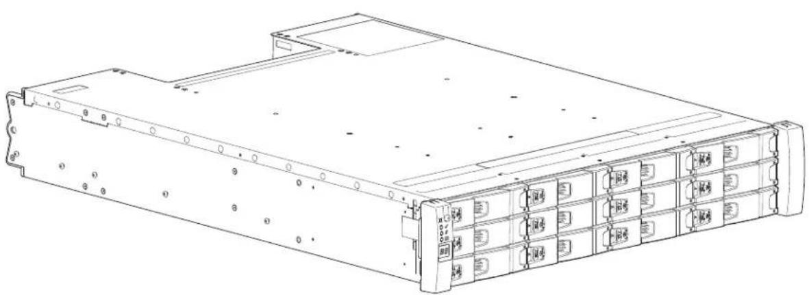
• 2U12 (rack space) RAID chassis – see Figure 1:
- Holds up to 12 low profile (1-inch high) 3.5" form factor drives in a horizontal orientation.
• The 2U12 RAID chassis ships with 12 drives installed.
Figure 1 2U12-Drive System (Front)
natural_image
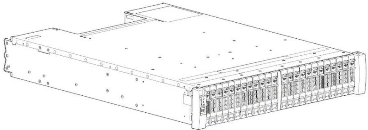
Line drawing of a server rack unit with multiple drive bays and ventilation slots (no text or labels)• 2U24 (rack space) RAID chassis – see Figure 2:
- Holds up to 24 low profile (5/8 inch high) 2.5" form factor drives in a vertical orientation.
• The 2U24 RAID chassis ships with 24 drives installed.
Figure 2 2U24-Drive System (Front)
natural_image
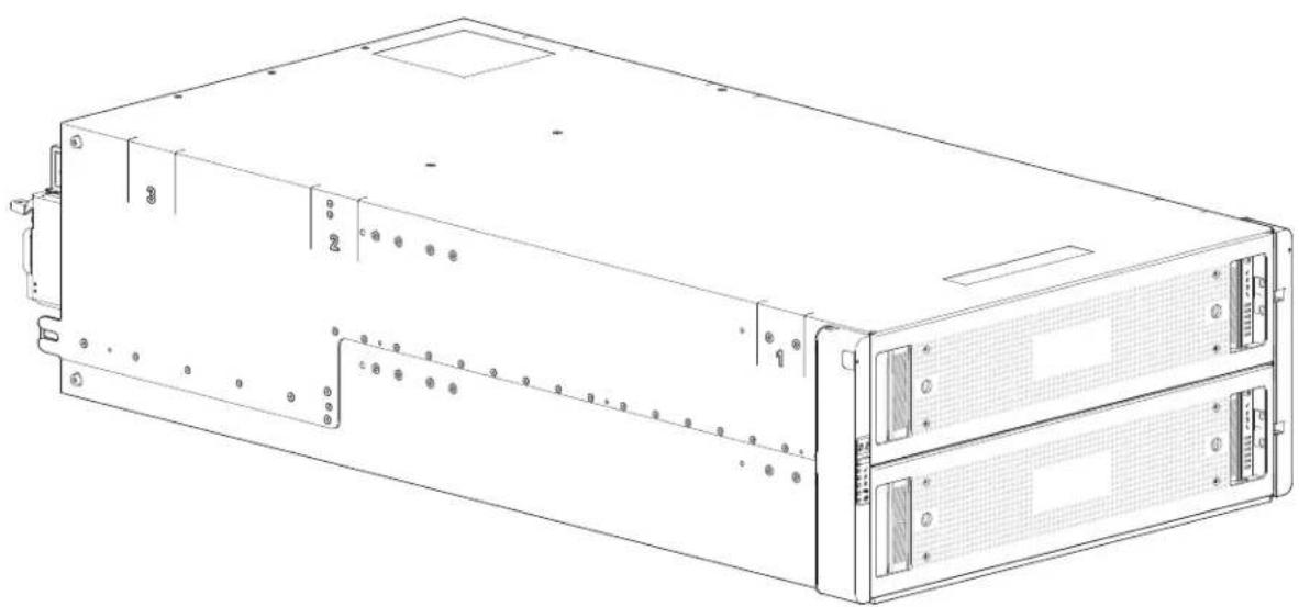
Line drawing of a server rack unit with multiple ports and connectors (no text or symbols visible)- 5U (rack space) RAID chassis – see Figure 3:
- Holds up to 84 low profile (1-inch high) 3.5" form factor drives in a vertical orientation within the drive drawer.
- Two vertically-stacked drawers each hold 42 drives.
- If used, 2.5" drives require 3.5" adapters.
• The 5U84 RAID chassis ships with no drives installed.
- Drives ship in a 42-drive pack (two each 42-drive packs for a total of 84 drives).
Figure 3 5U84-Drive System (Front)
natural_image
Line drawing of a server rack unit with two panels and mounting holes (no text or labels)IMPORTANT: These same chassis form factors are used for supported expansion chassis; albeit with different expansion I/O modules (IOMs). Each individual drive is hot pluggable and replaceable on site.
NOTE: Throughout this guide—and the management interfaces documents used with this guide—the RAID chassis has two RAID controllers installed and the expansion chassis has two expansion I/O modules (IOMs) installed.
CompactFlash
During a power loss or controller failure, data stored in cache is saved off to non-volatile memory (CompactFlash). The data is restored to cache, and then written to disk after the issue is corrected. To protect against writing incomplete data to disk, the image stored on the CompactFlash is verified before committing to disk. The CompactFlash memory card is located at the midplane-facing end of the controller module. Do not remove the card; it is used for cache recovery only.
NOTE: In dual-controller configurations featuring one healthy partner controller, there is no need to transport failed controller cache to a replacement controller because the cache is duplicated between the controllers, provided that volume cache is set to standard on all volumes in the pool owned by the failed controller.
Supercapacitor Pack
To protect controller module cache in case of power failure, each controller chassis model is equipped with supercapacitor technology, in conjunction with CompactFlash memory, built into each controller module to provide extended cache memory backup time.
The supercapacitor pack provides energy for backing up unwritten data in the write cache to the CompactFlash, in the event of a power failure. Unwritten data in CompactFlash memory is automatically committed to disk media when power is restored. In the event of power failure, while cache is maintained by the supercapacitor pack, the Cache Status LED blinks at a rate of 1/10 second on and 9/10 second off. See also Cache Overview and Status LED Details on page 45.
Front and Rear Views of QXS 12G Systems
This section provides the front and rear views of the QXS 12G Systems.
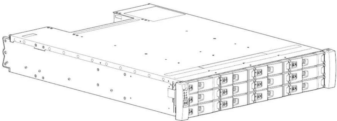
2U12-Drive System
Figure 4 provides a front view of the 2U12-drive system.
Figure 4 2U12-Drive System (Front)
natural_image
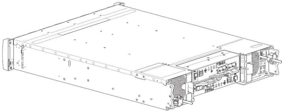
Line drawing of a server rack unit with multiple drive bays and ventilation slots (no text or labels)Figure 5 provides a rear view of the 2U12-drive system. The 2U12 RAID chassis has dual-controllers (4-port FC/iSCSI model shown) installed.
Figure 5 2U12-Drive System (Rear)
natural_image
Technical line drawing of a server rack with internal components and mounting holes (no text or symbols)2U12-Drive System Serial Number Label Location
This section provides the system serial number label location for the 2U12-drive systems.
NOTE: If you need Quantum support, you will need your system serial number. The 2U12 and the 2U24-drive system serial number label locations are the same.
The following illustrations provides a representative example of a system serial number label that is placed on a chassis.
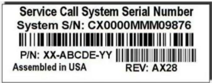
NOTE: Refer to Figure 6 and Figure 7 for the exact location of the system serial number label.
Do not confuse other "QTM" serial numbers on the chassis as the system serial number.
The 2U12 system serial number is located on a label attached to the rear of the chassis. The serial number label can be located on the left-rear ear of the chassis or on the right-rear ear of the chassis.
• The primary location of the serial number label is on the left-rear ear of the chassis.
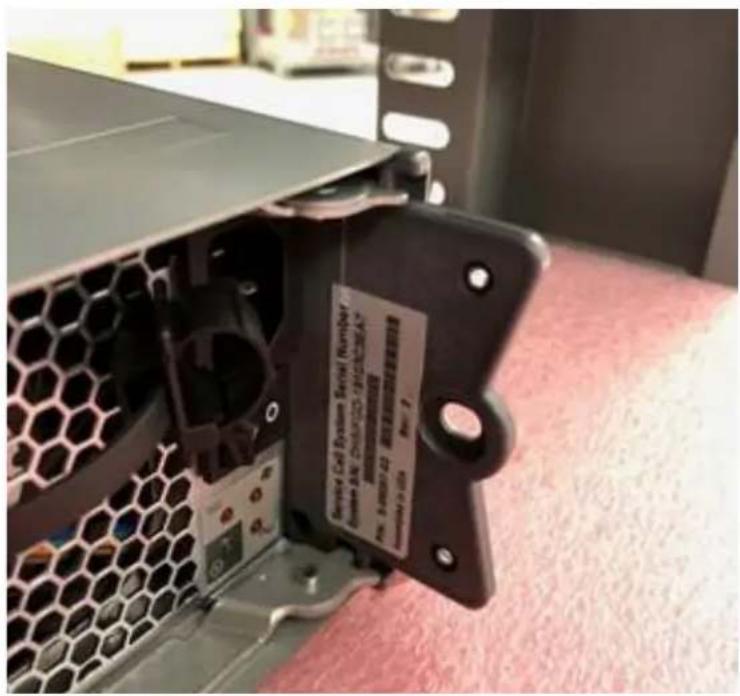
• However, some chassis might have a factory label on the left-rear ear of the chassis.
- When the chassis has a factory label on the left-rear ear, the system serial number label will be located on the right-rear ear of the chassis.
Figure 6 provides the serial number label location on the left-rear ear of the chassis.
Figure 6 Serial Number Label on Left-rear Ear of Chassis
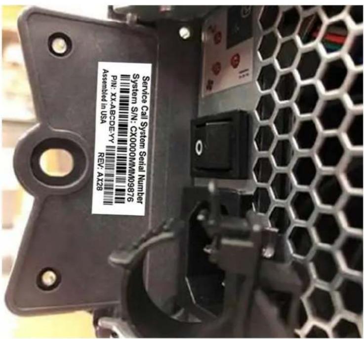
Figure 7 provides the serial number label location on the right-rear ear of the chassis.
Figure 7 Serial Number Label on Right-rear Ear of Chassis
2U24-Drive System
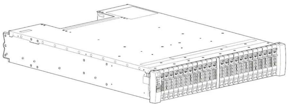
Figure 8 provides a front view of the 2U24-drive system.
Figure 8 2U24-Drive System (Front)
natural_image
Line drawing of a server rack unit with multiple ports and connectors (no text or symbols visible)Figure 9 provides a rear view of the 2U24-drive system. The 2U24 RAID chassis has dual-controllers (4-port FC/iSCSI model shown) installed.
Figure 9 2U24-Drive System (Rear)

natural_image
Technical line drawing of an internal server rack with ports and connectors (no text or symbols)2U24-Drive System Serial Number Label Location
This section provides the system serial number label location for the 2U24-drive systems.
NOTE: If you need Quantum support, you will need your system serial number. The 2U12 and the 2U24-drive system serial number label locations are the same.
The following illustrations provides a representative example of a system serial number label that is placed on a chassis.
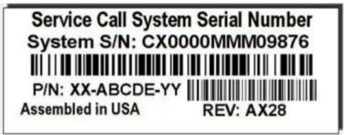
NOTE: Refer to Figure 10 and Figure 11 for the exact location of the system serial number label.
Do not confuse other "QTM" serial numbers on the chassis as the system serial number.
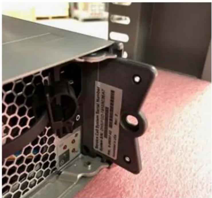
The 2U24 system serial number is located on a label attached to the rear of the chassis. The serial number label can be located on the left-rear ear of the chassis or on the right-rear ear of the chassis.
• The primary location of the serial number label is on the left-rear ear of the chassis.
• However, some chassis might have a factory label on the left-rear ear of the chassis.
- When the chassis has a factory label on the left-rear ear, the system serial number label will be located on the right-rear ear of the chassis.
Figure 10 provides the serial number label location on the left-rear ear of the chassis.
Figure 10 Serial Number Label on Left-rear Ear of Chassis
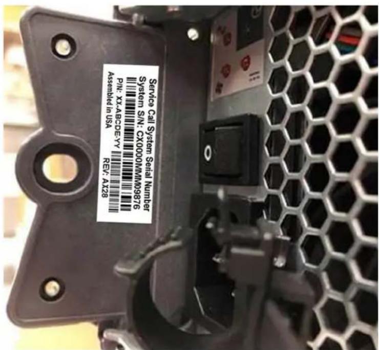
Figure 11 provides the serial number label location on the right-rear ear of the chassis.
Figure 11 Serial Number Label on Right-rear Ear of Chassis
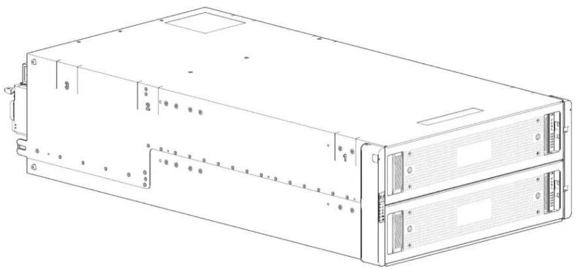
5U84-Drive System
Figure 12 provides a front view of the 5U84-drive system.
Figure 12 5U84-Drive System (Front)
natural_image
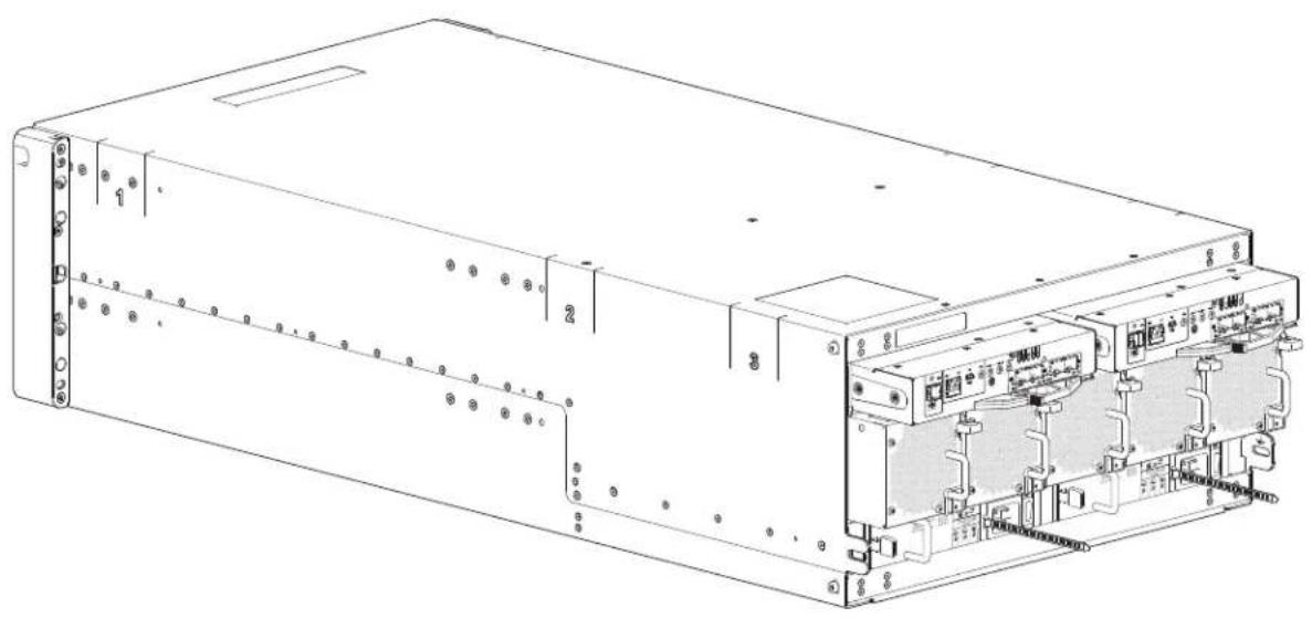
Line drawing of a server rack unit with multiple drive bays and ventilation slots (no text or labels)Figure 13 provides a rear view of the 5U84-drive system. The 5U84 RAID chassis has dual-controllers (4-port FC/iSCSI model shown) installed.
Figure 13 5U84-Drive System (Rear)
natural_image
Technical line drawing of an internal electronic device casing with ports and connectors (no text or symbols)5U84-Drive System Serial Number Label Location
This section provides the system serial number label location for the 5U84-drive systems.
The following illustrations provides a representative example of a system serial number label that is placed on a chassis.
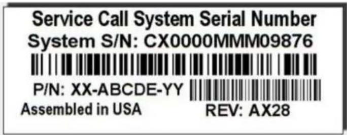
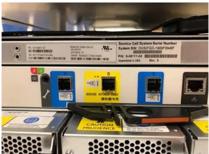
The 5U84 system serial number is located on a label attached to the rear of the chassis.
• Top-left of the chassis (right of the factory label)
- Above Controller A or Expansion IOM A
Figure 14 5U84 System Serial Number Label Location
Chassis Variants
The 2U chassis can be configured as a RAID chassis or an expansion chassis. The 5U chassis can be configured as a RAID chassis or an expansion chassis.
Table 3 provides the chassis variants.
Table 3 Chassis Variants
| Product Configuration | Drives PSUs | 1 | I/O Modules Fan Modules^3 | Bezel^4 | ||||
| 2U12 RAID Chassis | 12Gb/s direct dock drives | 12 LFF• 3.5" SAS• 3.5" SATA | 2 | 2 C | o | n | t | r o |
| 2U12 Expansion Chassis | 12Gb/s direct dock drives | 12 LFF• 3.5" SAS• 3.5" SATA | 2 | 2 E IOMs^2 | N/A | p | 1 a | n s |
Table 3 Chassis Variants
| Product Configuration | Drives PSUs | 1 | I/O Modules | Fan Modules^3 | Bezel^4 | ||||
| 2U24 RAID Chassis | 12Gb/s direct dock drives | 24 SFF• 2.5" SAS• 2.5" SATA | 2 | 2 C | o n | t | r | o | |
| 2U24 Expansion Chassis | 12Gb/s direct dock drives | 24 SFF• 2.5" SAS• 2.5" SATA | 2 | 2 E IOMs^2 | N/A 1 p | a | n | s | |
| 5U84 RAID Chassis | 12Gb/s direct dock drives | 84 LFF or SFF• 2.5" and 3.5" SAS• 3.5" SATA | 2 | 2 C | 5^3 n | 2 t | r | o | |
| 5U84 Expansion Chassis | 12Gb/s direct dock drives | 84 LFF or SFF• 2.5" and 3.5" SAS• 3.5" SATA | 2 | 2 E IOMs^2 | 5^3 p | 2 a | n | s | |
PSUs ^1 : Redundant PSUs must be compatible modules of the same type (both AC). Power cords are shipped with all chassis.
IOMs ^2 : Supported expansion IOMs are used in expansion chassis for adding storage.
Fan Modules ^3 : The fan modules are separate CRUs and not integrated within the PSUs. Fan modules are only used within the 5U84 drive chassis.
Bezel ^4 : Bezels ship as follows:
- The 2U12 chassis has a bezel shipped in a separate box and must be installed on site.
- The 2U24 chassis has a bezel shipped in a separate box and must be installed on site.
- The 5U84 chassis ships with the bezels (2 each) installed on the upper drawer (Drawer 0) and the lower drawer (Drawer 1).
Note: Ethernet cables are shipped with all RAID chassis.
IMPORTANT: The RAID chassis support dual-controller configuration only. If a partner controller fails, the storage system will fail over and run on a single controller module until the redundancy is restored. A RAID controller or expansion IOM must be installed in IOM slot to ensure sufficient air flow through the chassis during operation.
2U Chassis Core Product
The design concept is based on a chassis subsystem together with a set of plug-in modules. A typical chassis—as supplied—including the following:
- A chassis which includes the midplane PCB and an integral operator's (Ops) panel that is mounted on the left ear flange at the front of the chassis.
-
A bezel shipped in a separate box and must be installed on site.
-
Two 580W, 100–240V AC PSUs (with power cords). See also Figure 41 on page 36.
- Two RAID controllers (with Ethernet cable) or two expansion IOMs: 2 x SBB-compliant interface slots.
- Up to 12 or 24 drive modules in the 2U chassis.
- Where appropriate the drive carriers will include an Interposer card.
• See also Chassis Variants on page 14. drive blanks must be installed in all empty drive slots.
• A rail kit for rack mounting.
NOTE: The following figures show component locations—together with CRU slot indexing—relative to 2U chassis front and rear panels.
2U12-Drive Chassis Front View
Integers on the drives indicate drive slot numbering sequence (0-11). Figure 15 provides a front view of the 2U12-drive chassis.
Figure 15 2U12-Drive Chassis Front View

2U24-Drive Chassis Front View
Integers on the drives indicate drive slot numbering sequence (0-23). Figure 16 provides a front view of the 2U24-drive chassis.
Figure 16 2U24-Drive Chassis Front View

QXS-312 12G and QXS-324 12G RAID Chassis Rear View (2-Host Port Controllers)
NOTE: The 2U12-drive and 2U24-drive RAID chassis (2-host port controllers) rear views look identical. Figure 19 provides an illustration of the chassis rear view with two CNC controllers (2 FC/iSCSI ports).
Refer to the numbers on the CRUs, Figure 17, and the table to identify components within the 2U chassis. PSU and controller modules are available as CRUs. The RAID chassis use 2-port controller modules. Use expansion chassis for optionally added storage.
QXS-312 12G and QXS-324 12G RAID Chassis (CNC Controllers and 2FC/iSCSI ports)
Figure 17 provides a rear view of the 2U12-drive or 2U24-drive RAID chassis with two CNC controllers (2 FC/iSCSI ports).
Figure 17 2U12-Drive/2U24-Drive RAID Chassis (2 FC/iSCSI ports)
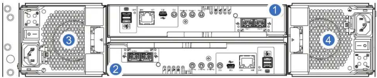
1 Controller A
2 Controller B
3 PSU0
CNC FC/iSCSI Controller
Callout 1, Figure 18, is the Controller A location. Callout 2, Figure 18, is the Controller B location. Both controllers are shown in the closed/locked position.
Figure 18 provides a rear view of the CNC FC/iSCSI controller used in the 2U12-drive or 2U24-drive systems. You can configure the CNC host interface ports (Ports 0 and 1) with 8/16Gb/s FC SFPs; 10GbE iSCSI SFPs; or 1Gb/s RJ-45 SFPs.
Figure 18 CNC FC/iSCSI Controller
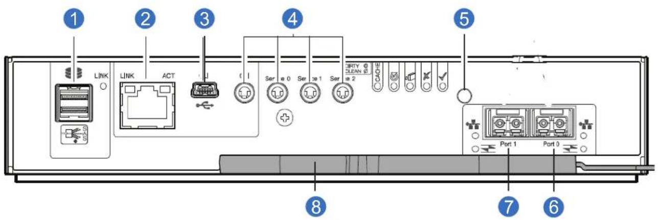
1 SAS Port
2 Ethernet Port
3 USB Port
4 Serial Ports (service only)
5 Reset
6 CNC Port 0
7 CNC Port 1
8 Lock/Release Handle
QXS-412 12G, QXS-424 12G, and QXS-484 12G RAID Chassis Rear View (4-Host Port Controllers)
NOTE: The QXS-412 12G, QXS-424 12G, and QXS-484 12G RAID chassis (4-host port controllers) rear views look identical.
Figure 19 provides an illustration of the chassis rear view with two CNC controllers (4 FC/iSCSI ports).
Refer to the numbers on the CRUs, Figure 19, and the table to identify components within the 2U chassis. PSU and controller modules are available as CRUs. The RAID chassis use 4-port controller modules. Use expansion chassis for optionally added storage.
RAID Chassis (CNC Controllers and 4 FC/iSCSI ports)
Figure 19 provides a rear view of the 2U12-drive or 2U24-drive RAID chassis with two CNC controllers (4 FC/iSCSI ports).
Figure 19 2U12-Drive/2U24-Drive RAID Chassis (4 FC/iSCSI ports)
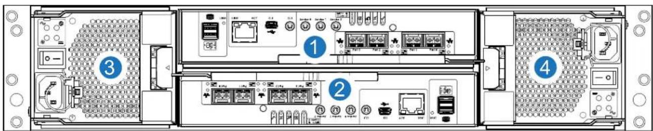
1 Controller A
2 Controller B
3 PSU0
4 PSU1
CNC FC/iSCSI Controller
Callout 1, Figure 19, is the Controller A location. Callout 2, Figure 19, is the Controller B location. Both controllers are shown in the closed/locked position.
Figure 20 provides a rear view of the CNC FC/iSCSI controller used in the 2U12-drive or 2U24-drive systems. You can configure the CNC host interface ports (Ports 0, 1, 2 and 3) with 8/16Gb/s FC SFPs; 10GbE iSCSI SFPs; or 1Gb/s RJ-45 SFPs.
Figure 20 CNC FC/iSCSI Controller
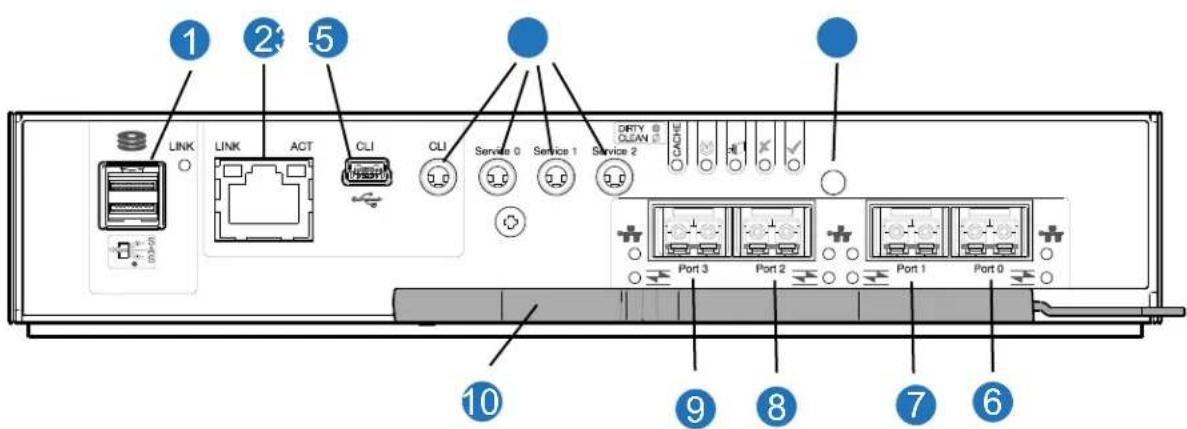
| 1 | SAS Port | 2 | Ethernet Port |
| 3 | USB Port | 4 | Serial Ports (service only) |
| 5 | Reset | 6 | CNC Port 0 |
| 7 | CNC Port 1 | 8 | CNC Port 2 |
| 9 | CNC Port 3 | 10 | Lock/Release Handle |
2U12-Drive/2U24-Drive Expansion Chassis Rear View
NOTE: The 2U12-drive and 2U24-drive expansion chassis rear views look identical. Figure 21 provides an illustration of the chassis rear view.
The top middle slot, Figure 21, is the Expansion IOM A location. The lower middle slot is the Expansion IOM B location. Both IOMs are shown in the closed/locked position.
Expansion Chassis
Figure 21 provides a rear view of the 2U12-drive or 2U24-drive expansion chassis rear panel. The expansion chassis attaches to the RAID chassis for additional storage.
Figure 21 2U12/2U24-Drive Expansion Chassis Rear View
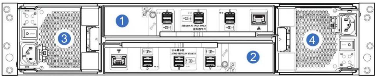
| 1 | IOM A | 2 | IOM B |
| 3 | PSU0 | 4 | PSU1 |
Expansion Chassis IOM
Figure 22 provides a rear view of the expansion chassis IOM used in the 2U12-drive or 2U24-drive systems. Ports A/B/C ship configured with 12Gb/s HD mini-SAS (SFF-8644) external connectors.
Figure 22 Expansion Chassis IOM
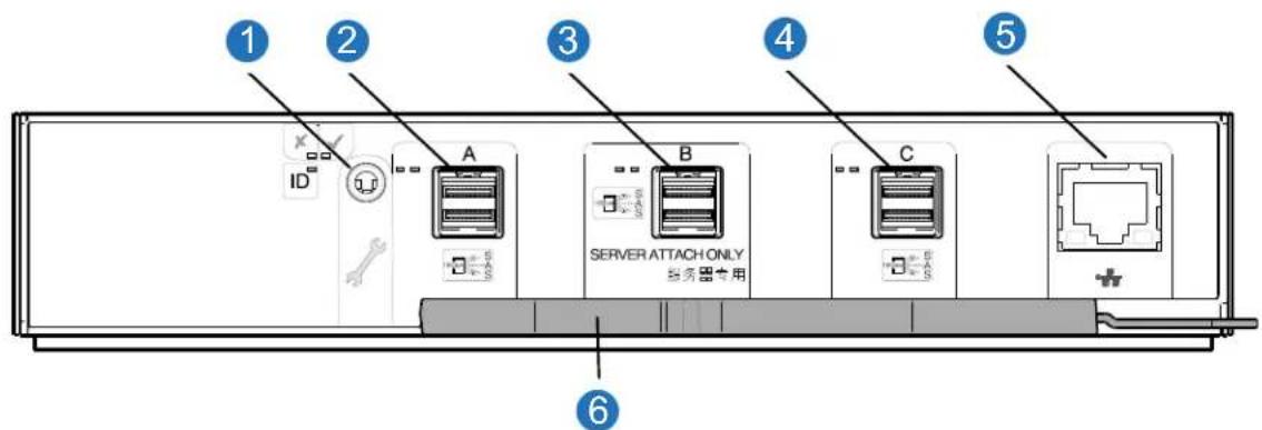
IMPORTANT: RAID chassis and expansion configurations:
- When the expansion chassis shown above (Figure 21) is used with RAID chassis for adding storage, its middle HD mini-SAS expansion port ("B") is disabled by the firmware.
- The Ethernet port on the expansion module is not used in RAID chassis and expansion configurations, and is disabled.
Power Supply Unit (PSU)
Figure 23 provides and illustration of the PSU used in the RAID chassis and the expansion chassis. They are identical in the 12-drive and 24-drive chassis. Figure 23 shows an example of a PSU oriented for use in the left PSU Slot 0 of the RAID or expansion chassis.
Figure 23 PSU
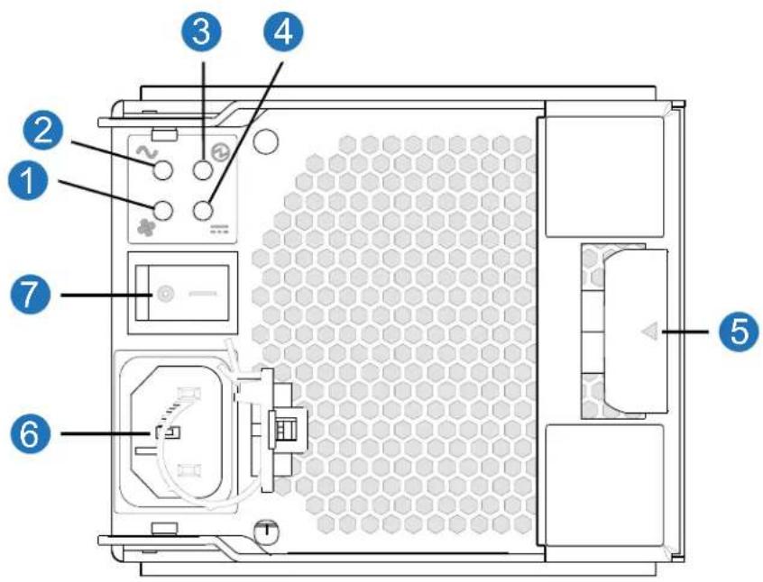
| 1 | Fan Fail LED | 2 | AC Fail LED |
| 3 | PSU OK LED | 4 | DC Fail LED |
| 5 | Release/Lock Handle | 6 | Power Connect |
| 7 | Power Switch |
2U RAID/Expansion Chassis
The 2U chassis consists of a sheet metal chassis with an integrated midplane PCB and module runner system.
NOTE: Customers select a chassis type and drives separately. All empty drive slots in the 2U chassis must have drive blanks installed.
The 2U chassis supports the following form factors:
• 2U12 chassis configured with 12 LFF disks (see Figure 15 on page 16) as follows:
- Twelve 3.5" SAS LFF disk drives, held horizontally
- Twelve 3.5" SATA LFF disk drives, held horizontally
• 2U24 chassis configured with 24 SFF disks (see Figure 16 on page 16) as follows:
- Twenty-four 2.5" SAS SFF disk drives, held vertically
- Twenty-four 2.5" SATA SFF disk drives, held vertically
• 2U12 empty chassis with midplane and module runner system: see Figure 24 on page 21
• 2U24 empty chassis with midplane: see Figure 25 on page 22
The chassis has a 19-inch rack mounting that enables it to be installed onto standard 19-inch racks and uses two EIA units of rack space (3.5") for a 2U chassis.
- The midplane PCB can support either 12 or 24 drive connections.
- There are either 12 or 24 drive slots at the front of the chassis, in horizontal (12) or vertical (24) orientation, as defined by the chassis variant.
• See also Figure 15 and Figure 16 on page 16.
• Each drive slot holds a plug-in drive carrier module that can hold these drive types, dependent upon the chassis type:
- At the rear, the chassis assembly can hold a maximum of two PSUs and two RAID controllers or SBB-compliant expansion IOMs.
Front of 2U12 RAID or Expansion Chassis
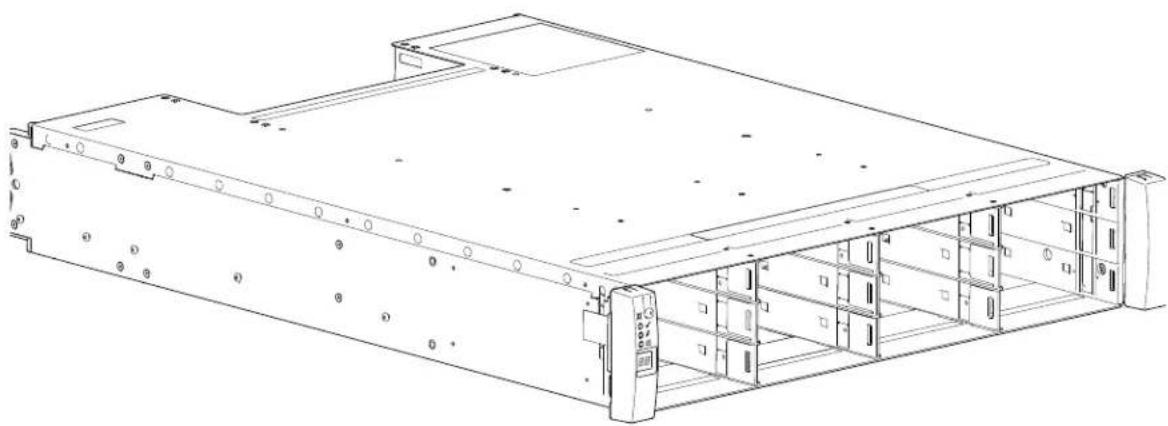
Figure 24 provides an illustration of the front of the 2U12 RAID or expansion chassis (without drives installed).
Figure 24 Front of 2U12 RAID or Expansion Chassis
natural_image
Technical line drawing of a server rack unit with mounting holes and drive bays (no text or labels)Front of 2U24 RAID or Expansion Chassis
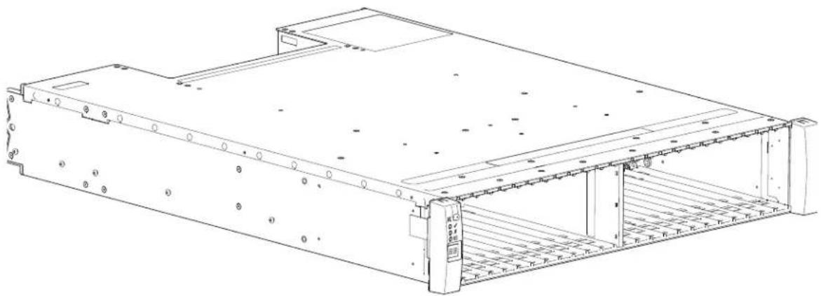
Figure 25 provides an illustration of the front of the 2U24 RAID or expansion chassis (without drives installed).
Figure 25 Front of 2U24 RAID or Expansion Chassis
natural_image
Technical line drawing of a server rack unit with mounting holes and ventilation grilles (no text or symbols)NOTE:
- Either 2U chassis can be configured as a RAID chassis (two controllers) or as an optional expansion chassis for adding storage.
- The 2U12 expansion chassis uses the same expansion IOMs as the 2U24 and 5U84 expansion chassis.
- The 2U24 expansion chassis uses the same expansion IOMs as the 2U12 and 5U84 expansion chassis.
5U Chassis Core Product
The 5U chassis consists of a sheet metal chassis, integrated PCBs, and a module runner system. The design concept is based on an chassis subsystem together with a set of plug-in modules. A typical chassis system—as supplied—includes the following:
• A chassis consisting of:
- Two sliding drawers containing Disk Drive in Carrier (DDIC) modules (42 drive slots per drawer).
• An Operator's (Ops) panel.
• A chassis drawer bezel. -
A midplane PCB into which other components and CRUs connect.
-
Two power supply units (PSUs) with power cords.
- Five cooling fans.
- Two RAID controllers (with Ethernet cable) or two expansion IOMs: 2 x SBB-compliant interface slots.
- Up to 84 DDIC modules populated within two drawers (42 DDICs per drawer; 14 DDICs per row) as follows:
• 2.5" SFF or 3.5" LFF SAS drives
• 3.5" SATA LFF drives
• A rail kit for rack mounting.
IMPORTANT: To ensure sufficient circulation and cooling throughout the chassis, all PSU slots, cooling fan slots, RAID controller, and expansion IOM slots must contain a functioning CRU. Do not replace a faulty CRU until the replacement is available in hand.
5U Chassis Front View
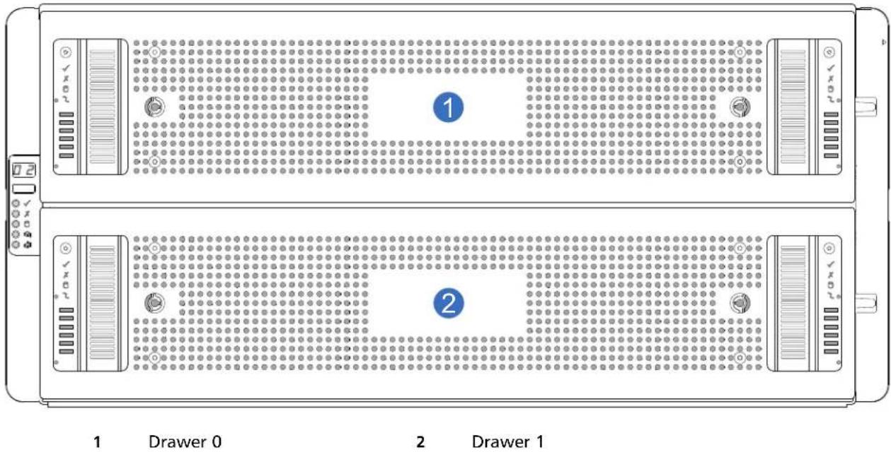
Figure 26 provides an illustration of the front of the 5U84 RAID or expansion chassis (with bezel installed). Drawer 0 is at the top of the chassis. Drawer 1 is at the bottom of the chassis.
Figure 26 Front of 5U84 RAID or Expansion Chassis
5U Chassis Drive Slots View
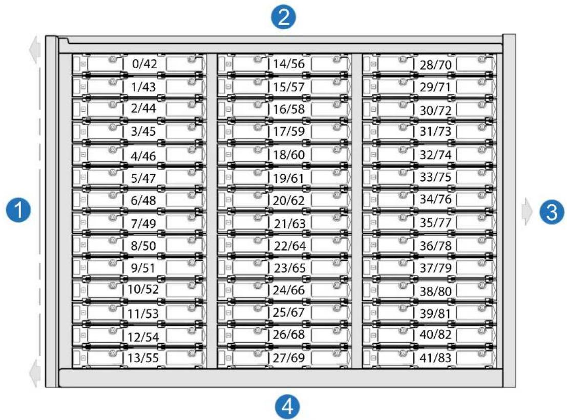
Figure 27 provides an illustration of the 5U84 RAID or expansion chassis (drive slots view) with the drawer open. There are a total of 84 drive slots in the two drawers.
- Drawer 0 has drive slots 0-41 (42 drives can be installed)
- Drawer 1 has drive slots 42-83 (42 drives can be installed)
IMPORTANT: Drawer sideplanes—also known as side cards—can be hot-swapped as field-replaceable units (FRUs).
However, these FRUs require a special tool, and replacement should be performed by qualified service personnel only.
Contact your service provider for more information.
NOTE: Figure 27 displays the front of the drawer on the left side of the illustration. The back of the drawer is on the right side of the illustration.
Figure 27 5U84 RAID or Expansion Chassis Drive Slots
bar
| Row | Column | Value | |---|---|---| | 1 | 0/42 | 14/56 | | 1 | 1/43 | 15/57 | | 1 | 2/44 | 16/58 | | 1 | 3/45 | 17/59 | | 1 | 4/46 | 18/60 | | 1 | 5/47 | 19/61 | | 1 | 6/48 | 20/62 | | 1 | 7/49 | 21/63 | | 1 | 8/50 | 22/64 | | 1 | 9/51 | 23/65 | | 1 | 10/52 | 24/66 | | 1 | 11/53 | 25/67 | | 1 | 12/54 | 26/68 | | 1 | 13/55 | 27/69 | | 2 | 28/70 | 28/70 | | 2 | 29/71 | 29/71 | | 2 | 30/72 | 30/72 | | 2 | 31/73 | 31/73 | | 2 | 32/74 | 32/74 | | 2 | 33/75 | 33/75 | | 2 | 34/76 | 34/76 | | 2 | 35/77 | 35/77 | | 2 | 36/78 | 36/78 | | 2 | 37/79 | 37/79 | | 2 | 38/80 | 38/80 | | 2 | 39/81 | 39/81 | | 2 | 40/82 | 40/82 | | 2 | 41/83 | 41/83 | The image contains a diagram with numbered labels (1, 2, etc.) and arrows pointing to the left side of the diagram. The numbers in the table are explicitly labeled on each panel.1 Drawer 0/1 Front
2 Drawer 0/1 Left Side
3 Drawer 0/1 Rear (slides into chassis)
4 Drawer 0/1 Right Side
5U84 RAID Chassis (Rear View/Two CNC Controllers)
Figure 28 on page 25 provides an illustration of the 5U84 RAID chassis rear view with two CNC controllers (FC/iSCSI, 4-ports) installed.
NOTE: The 5U84 RAID chassis supports attachment of expansion chassis for adding storage.
Refer to Figure 28 for all the 5U84 Raid chassis CRUs with CNC controllers.
Figure 28 5U84 RAID Chassis Rear View (CNC Controllers)
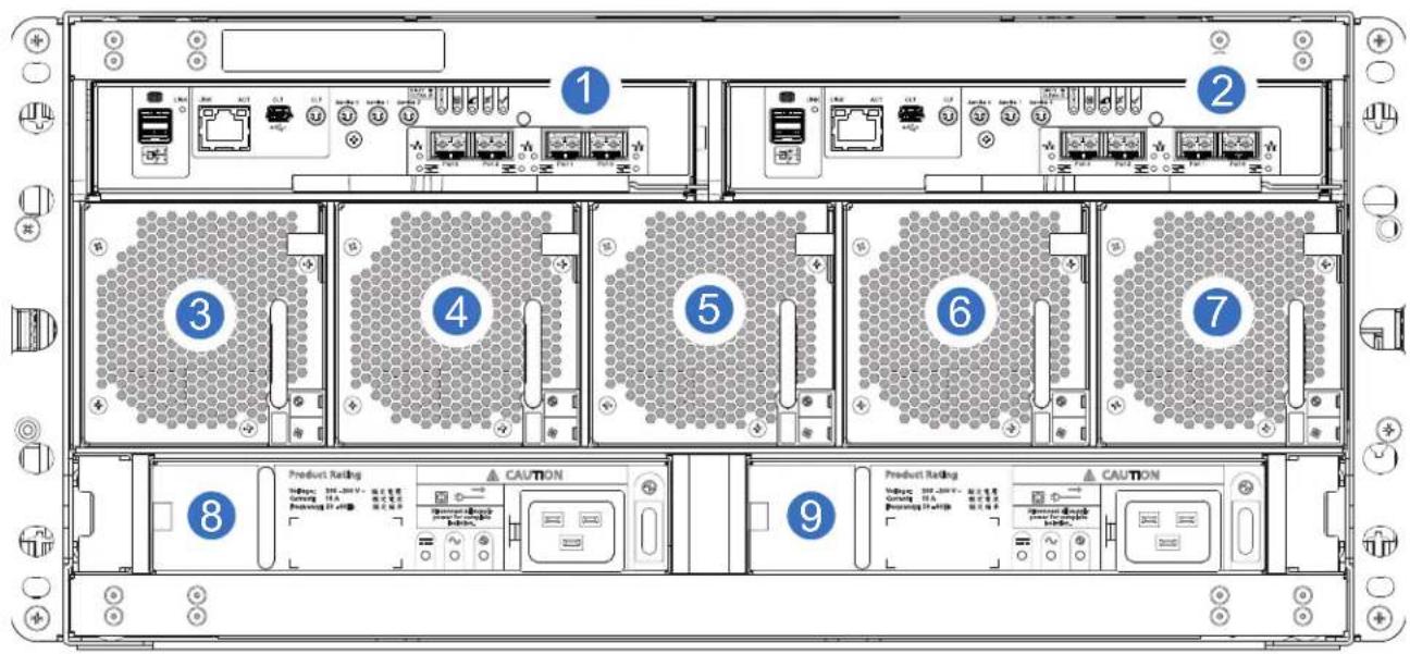
1 Controller A 2 Controller B 3 Fan 0
4 Fan 1 5 Fan 2 6 Fan 3
7 Fan 4 8 PSU 0 9 PSU 1
CNC FC/iSCSI Controller
Callout 1, Figure 28, is the Controller A location. Callout 2 Figure 28, is the Controller B location. Both controllers are shown in the closed/locked position.
Figure 29 provides a rear view of the CNC FC/iSCSI controller used in the 5U84-drive systems. You can configure the CNC host interface ports (Ports 0, 1, 2 and 3) with 8/16Gb/s FC SFPs; 10GbE iSCSI SFPs; or 1Gb/s RJ-45 SFPs.
Figure 29 CNC FC/iSCSI Controller
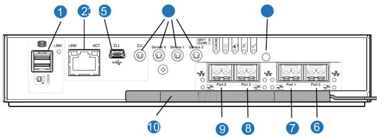
| 1 | SAS Port | 2 | Ethernet Port |
| 3 | USB Port | 4 | Serial Ports (service only) |
| 5 | Reset | 6 | CNC Port 0 |
| 7 | CNC Port 1 | 8 | CNC Port 2 |
| 9 | CNC Port 3 | 10 | Lock/Release Handle |
5U84 Expansion Chassis (Rear View)
Figure 30 provides an illustration of the 5U84 expansion chassis rear view with two expansion IOMs (2-SAS ports used) installed.
Refer to Figure 30 for all the 5U84 expansion chassis CRUs with expansion IOMs.
NOTE: The 5U84 expansion chassis uses the same expansion IOMs as the 2U12 and 2U24 expansion chassis.
Figure 30 5U84 Expansion Chassis Rear View (SAS)
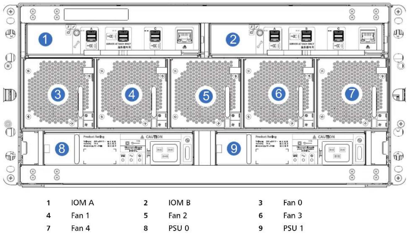
Expansion Chassis IOM
Figure 31 provides a rear view of the expansion chassis IOM used in the 5U84-drive systems. Ports A/B/C ship configured with 12Gb/s HD mini-SAS (SFF-8644) external connectors.
Figure 31 Expansion Chassis IOM
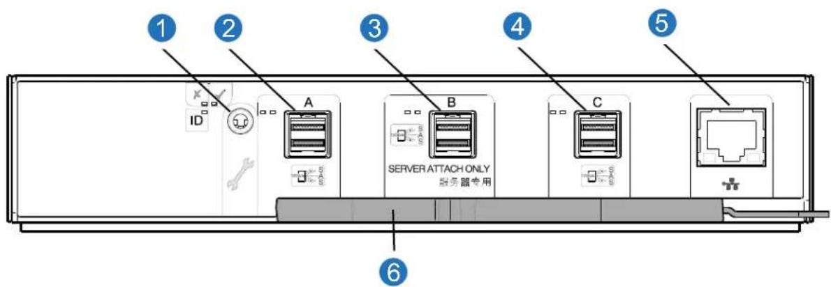
IMPORTANT: RAID chassis and expansion configurations:
- When the expansion chassis shown above (Figure 30) is used with RAID chassis for adding storage, its middle HD mini-SAS expansion port ("B") is disabled by the firmware.
- The Ethernet port on the expansion module is not used in RAID chassis and expansion configurations, and is disabled.
Power Supply Unit (PSU)
Figure 32 provides and illustration of the PSU used in the 5U84 RAID chassis and the expansion chassis (oriented for use in the left PSU Slot 0 and right PSU Slot 1).
Figure 32 5U84 Chassis PSU
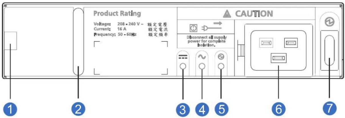
| 1 | Release Latch | 2 | Handle |
| 3 | PSU Fault | 4 | AC Fail |
| 5 | Power OK | 6 | Power Connect |
| 7 | Power Switch |
Fans
Figure 33 provides and illustration of the fan used in the 5U84 RAID chassis and the expansion chassis. The 5U84 RAID or expansion chassis uses five fans for sufficient cooling and air flow for the chassis. Figure 33 shows an example of a fan oriented for use in the Fan 0, Fan 1, Fan 2, Fan 3, and Fan 4 slots of the RAID or expansion chassis.
Figure 33 5U84 Chassis Fan
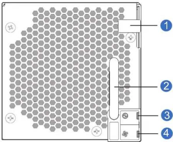
| 1 | Release Latch | 2 | Handle |
| 3 | Fan OK | 4 | Fan Fault |
5U Chassis
The 5U chassis consists of a sheet metal chassis with an integrated midplane PCB, module runner system, and two drawers for drive modules.
NOTE: Customers select a chassis type and drives separately. Empty drive slots in the 5U chassis require drive blanks. The 5U84 chassis (Figure 27 on page 24) can be configured as follows:
• 2.5" SFF or 3.5" LFF SAS drives
- 3.5" LFF SATA drives
Additional characteristics include:
- The chassis has a 19-inch rack mounting that enables it to be installed onto standard 19-inch racks and uses five EIA units of rack space (8.75") for a 5U84 chassis.
- At the front of the chassis two drawers can be opened and closed.
• Each drawer provides access to 42 slots for Disk Drive in Carrier (DDIC) modules.
- DDICs are top mounted into the drawers.
- The front of the chassis also provides chassis status LEDs and drawer status/activity LEDs.
- At the rear of the chassis, access is provided to rear panel CRUs:
- Two SBB-compliant RAID controllers or expansion IOMs
- Two PSUs
- Five fan cooling modules
5U Chassis Drawers
Each chassis drawer contains 42 slots, each of which can accept a single DDIC containing a 3.5" LFF drive or a 2.5" SFF drive with an adapter. See Figure 26 on page 23 and Figure 27 on page 24.
Opening a drawer does not interrupt the functioning of the storage system, and DDICs can be hot-swapped while the chassis is in operation. However, drawers must not be left open for longer than 2 minutes, or airflow and cooling will be compromised.
IMPORTANT: During normal operation, drawers should be closed to ensure proper airflow and cooling within the chassis.
A drawer is designed to support its own weight, plus the weight of installed DDICs, when fully opened.
Safety features
The chassis safety features include:
• To reduce the possibility of toppling, only one drawer can be open at a time.
- The drawer locks into place when fully opened and extended.
- To reduce pinching hazards, two latches must be released before the drawer can be pushed back into the drawer slot within the chassis.
Power and data are sent via three baseplanes and two sideplanes. The direct-dock SATA version of the 5U chassis has one active and one passive sideplane, and has dual power paths, but only a single data path.
Locking Drawer
Each drawer can be locked shut by turning both anti-tamper locks clockwise using a screwdriver with a Torx T20 bit. The anti-tamper locks are symmetrically placed on the left-hand and right-hand sides of the drawer bezel.
Drawer status and activity LEDs can be monitored via two Drawer LEDs panels located next to the two drawer-pull pockets located on the left-hand and right-hand side of each drawer. Figure 34 on page 30 provides the location of the drawer LEDs panel (left and right side.
Figure 34 Drawer/Bezel LED Panel
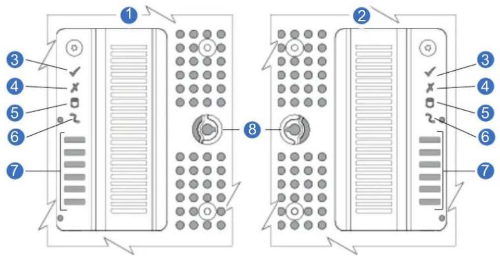
1 Left Side of Chassis
2 Right Side of Chassis
3 Sideplane OK/Power Good
4 Drawer Activity
5 Logical Fault
6 Cable Fault
7 Drawer Activity Indicators Bar Graph
8 Anti-tamper Lock
2U Operator's (Ops) Panel
Each of the chassis supported by QXS-312 12G, QXS-324 12G, QXS-412 12G, QXS-424 12G, and QXS-484 12G systems feature an Ops panel located on the chassis left ear flange. The Ops panel for 2U12 and 2U24 chassis are identical.
A flexible cable connects the Ops panel to the midplane. The Ops panel is a passive component: the midplane controls the panel, and the RAID controllers or expansion IOMs control all the panel's functions.
2U12 Chassis Ops Panel
Figure 35 provides a front view of the 2U12 chassis with the ops panel.
Figure 35 2U12 Chassis Ops Panel
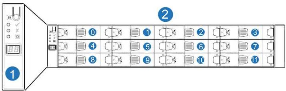
1 Ops Panel
2 2U12 Chassis
Note: Drives are numbered from 0-11 (12 drives).
2U24 Chassis Ops Panel
Figure 36 provides a front view of the 2U24 chassis with the ops panel.
Figure 36 2U24 Chassis Ops Panel
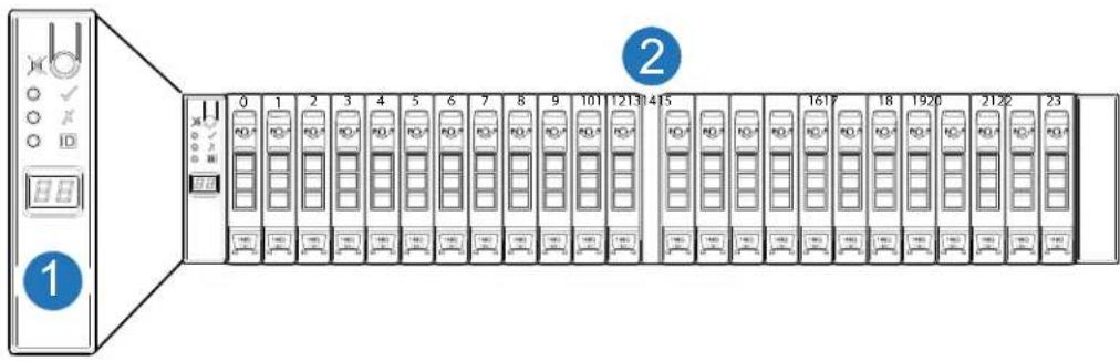
1 Ops Panel
2 2U24 Chassis
Note: Drives are numbered from 0-23 (24 drives).
2U12 and 2U24 Ops Panel Functions
An integral part of the chassis, the Ops panel is not replaceable on site. The Ops panel provides the functions shown in the illustration below and listed in the table. See also 2U Chassis Ops Panel LEDs on page 117.
Figure 37 2U Chassis Ops Panel Functions
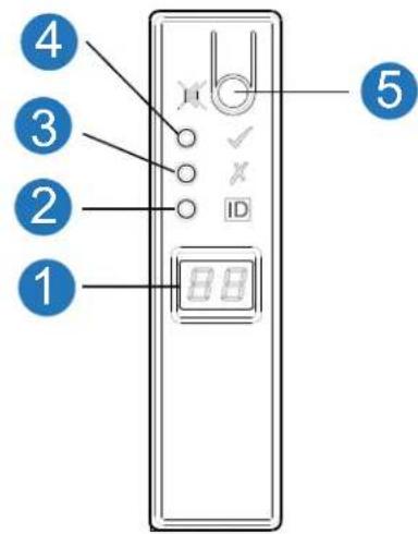
LED Status
1 Unit Identification Display Green: Seven segment display: chassis sequence
2 Identity Blue: Power On (5s) test state
3 Module Fault Constant or blinking amber: fault present
4 System Power On/Standby Constant Green: positive indication Constant Amber: fault present
5 Mute Button Not used
Note: Chassis has a thermal sensor behind the ops panel.
System Power On/Standby LED (green/amber)
LED displays amber when only standby power is available. LED displays green when system power is available.
Module Fault LED (amber)
LED illuminates when experiencing a system hardware fault. It may be associated with a Fault LED on a PSU, RAID controller, or expansion IOM that helps the user to identify which component is causing the fault.
Location LED (blue)
When activated, the Identity LED blinks at a rate of 1s on, 1s off to easily locate the chassis within a data center. The locate function may be enabled/disabled through SES (SCSI Enclosure Services).
NOTE: Activate the Location LED by using the disk management utility (GUI) or CLI.
Unit Identification Display
The UID is a dual seven-segment display that can be used to provide feedback to the user. Its primary function is to display a chassis unit identification number to assist users in setting and maintaining multiple chassis systems.
Thermal sensor
The thermal sensor is located on the outside of the chassis, and it sends input to the chassis (RAID controller/expansion IOM) about its external operating ambient temperature.
5U Chassis Ops Panel
The 5U84 chassis front panel has an Ops panel mounted on the left ear flange. A flexible cable connects the Ops panel to the midplane. The Ops panel is a passive component: the midplane controls the panel, and the RAID controllers or expansion IOMs control all the panel's functions.
Chassis Ops Panel Location
Figure 38 provides a front view of the 5U84 chassis with the ops panel.
Figure 38 5U84 Chassis Ops Panel
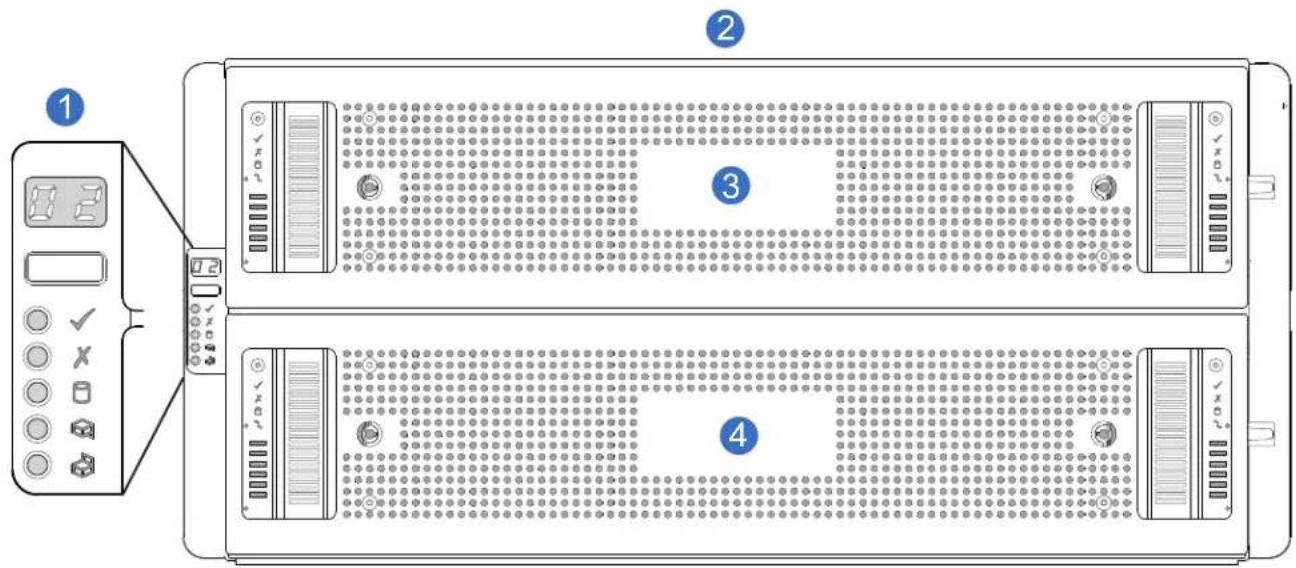
1 Ops Panel
2 5U84 Chassis
3 Drawer 0
4 Drawer 1
Note: The 5U84 ops panel is different from the 2U12 and 2U24 units.
Ops Panel Functions
An integral part of the chassis, the Ops panel is not replaceable on site. The Ops panel provides the functions shown in the illustration below and listed in the table. The 5U ops panel provides the following:
• Unit Identification Display (UID)
- Mute/Input button
• Power On/Standby LED (green/amber)
- Module Fault LED (amber)
• Logical Status LED (amber)
• Top Drawer Fault LED (amber)
- Bottom Drawer Fault LED (amber)
Figure 39 5U Chassis Ops Panel Functions
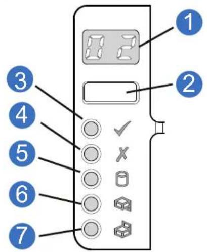
LED Status
1 Unit Identification Display Green: Seven segment display: chassis sequence
2 Input Switch Not used
3 System Power On/Standby Constant Green: positive indication
Constant Amber: system in standby (not operational)
4 Module Fault Constant or blinking amber: fault present
5 Logical Status Constant or blinking amber: fault present
6 Top Drawer Fault Constant or blinking amber: fault present in drive, cable, or sideplane.
7 Bottom Drawer Fault Constant or blinking amber: fault present in drive, cable, or sideplane.
Unit Identification Display
The UID is a dual seven-segment display that can be used to provide feedback to the user. Its primary function is to display a chassis unit identification number to assist users in setting and maintaining multiple chassis systems.
System Power On/Standby LED (green/amber)
LED displays amber when only standby power is available (non-operational). LED displays green when system power is available (operational).
Module Fault LED (amber)
LED illuminates when experiencing a system hardware fault. It may be associated with a Fault LED on a PSU, fan, RAID controller or expansion IOM, DDIC, or drawer that helps the user to identify which component is causing the fault.
Logical Status LED (amber)
This LED indicates a change of status or fault from something other than the chassis management system. This may be initiated from the controller module or an external HBA. The indication is typically associated with a DDIC and LEDs at each disk position within the drawer, which help to identify the DDIC affected.
Drawer Fault LEDs (amber)
This LED indicates a disk, cable, or sideplane fault in the drawer indicated: Top (Drawer 0) or Bottom (Drawer 1).
PSUs - 2U CRU
The 2U12 and 2U24 use the same type of PSUs. AC-DC power is provided by up to two auto-ranging power PSUs with integrated axial cooling fans. The RAID controllers and expansion IOMs control fan speed.
PSU Features
The 580W PSU voltage operating range is nominally 100V–240V AC, and operates at 50–60 Hz input frequency. Figure 41 provides a representative illustration of the PSUs in a 2U chassis. PSU0 and PSU1 are installed 180 degrees as compared to each other (callouts 3 and 4).
NOTE: Controller A and Controller B are also installed 180 degrees as compared to each other (callouts 1 and 2).
Figure 40 2U12-Drive/2U12-Drive RAID Chassis (4 FC/iSCSI ports)

1 Controller A
2 Controller B
3 PSU0
4 PSU1
Figure 41 provides an illustration of the PSU (with LEDs) for the 2U12 and 2U24 chassis. The diametric rear orientation in Figure 41 shows the PSU aligned for insertion into the right-hand PSU slot (PSU1) located on the 2U12 or 2U24 chassis rear panel.
Figure 41 PSU 2U12/2U24 Chassis
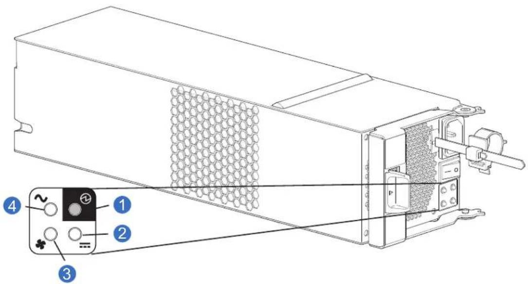
1 PSU OK LED: Green 2 DC Fail LED: Amber/blinking amber
3 Fan Fail LED: Amber/blinking amber 4 AC Fail LED: Amber/blinking amber
Multiple PSUs
The 2U12 and 2U24 storage systems include two PSUs which provide redundant power control for the system so that if one PSU fails, the other maintains the power supply, and chassis operation is not affected while you replace the faulty PSU.
PSUs are hot-pluggable, and replacement should only take a few seconds to do. Replacement must be completed as soon as possible after the removal of the defective PSU to avoid a thermal exception. The replacement procedure should be completed within an absolute maximum of 2 minutes.
Operation of the chassis with any modules missing will disrupt the airflow, and the drives will not receive sufficient cooling. It is essential that all slots are fitted with PSUs prior to powering on the chassis.
System Airflow
The system must be operated with low pressure rear exhaust installation. Back pressure created by rack doors and obstacles is not to exceed 5 pascals (0.5mm water gauge). The cooling system provides sufficient capacity to ensure that maximum temperatures are not exceeded.
The environment in which the chassis operates must be dust-free to ensure adequate airflow.
PSU - 5U CRU
Power is provided by two 2,214W PSUs. The PSU voltage operating range is nominally 200V–240V AC, and operates at 50–60 Hz input frequency. The dimetric rear orientation in Figure 42 shows the PSU aligned for insertion into its slot located on the chassis rear panel.
Figure 42 PSU 5U84 CRU
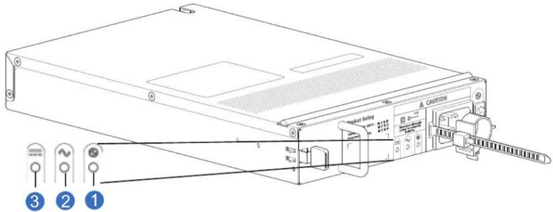
1 PSU OK LED: Green
2 AC Fail LED: Amber/blinking amber
3 PSU Fail LED: Amber/blinking amber
NOTE: If any of the PSU LEDs are illuminated amber, a module fault condition or failure has occurred.
Dual PSUs provide redundant power for the 5U system: if one PSU fails, the other keeps the system running while you replace the faulty module. PSUs are hot-swappable. Replacement of a PSU can be performed while the chassis is running, but the procedure must be completed within two minutes of the removal of the defective module. Verify that you have a replacement PSU on hand before removing the defective module.
Fan - 5U CRU
The five fans at the rear of the chassis maintain all system components below their maximum temperature, assuming the ambient temperature is below 35^ C. Fan speed is governed by the controller modules.
Fans are hot-swappable. Replacement of a fan can be performed while the chassis is running, but the procedure must be completed within two minutes of the removal of the defective module. Verify that you have a replacement module on hand before removing the defective fan.
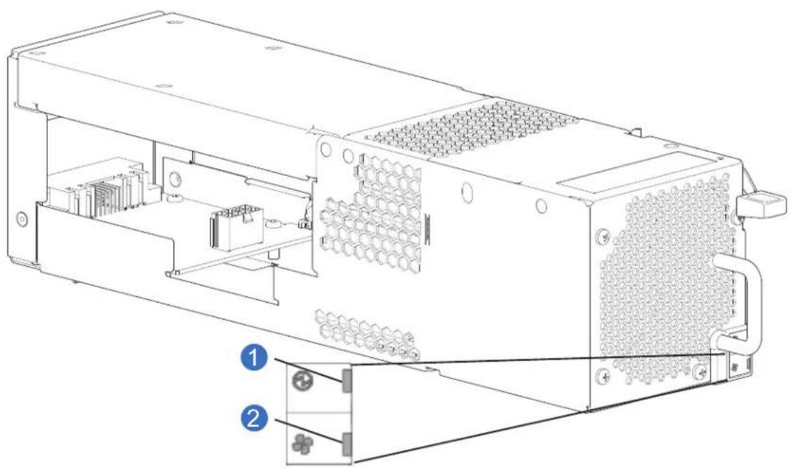
Figure 43 provides an illustration of the fan (with LEDs) for the 5U84 chassis.
Figure 43 Fan 5U84 CRU
natural_image
Technical line drawing of an electronic device chassis with internal components and labeled parts (no text or symbols beyond labels)1 Fan OK LED: Green
2 Fan Fault LED: Amber/blinking amber
Note: If any of the fan LEDs are illuminated amber, a module fault condition or failure has occurred.
RAID Controller and Expansion IOMs
This section describes the RAID controllers and expansion IOMs used in QXS-312 12G, QXS-324 12G, QXS-412 12G, QXS-424 12G, and QXS-484 12G systems. They are mechanically and electrically compliant to the latest SBB v2.1 specification.
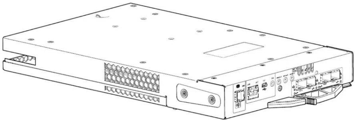
The diametric rear orientation in Figure 44 shows a 4-port FC/iSCSI controller module aligned for use in the top controller module slot located on the 2U chassis rear panel. The controller module is also properly aligned for use in either controller slot located on the 5U chassis rear panel.
Figure 44 provides an illustration of the CNC controller (FC/iSCSI) for the 2U12, 2U24, and 5U84 chassis.
Figure 44 CNC Controller CRU
natural_image
Line drawing of a server rack with ports, connectors, and ventilation grilles (no text or symbols)Each controller module maintains VPD (Vital Product Data) in EEPROM devices, and are interconnected by SBB-defined I2C buses on the midplane. In this way, the SBB modules can discover the type and capabilities of the partner SBB module(s), and vice versa, within the chassis. A system alarm occurs when incompatible configurations are detected.
12Gb/s Controller LEDs
The diagrams with tables that immediately follow provide descriptions for the different controller modules that can be installed into the rear panel of a RAID chassis. Showing controller modules separately from the chassis enables improved clarity in identifying the component items called out in the diagrams and described in the companion tables within the figure/table ensembles.
NOTE: Consider the following when viewing RAID controller or expansion IOM diagrams appearing on the following pages:
- In each diagram, the canister is oriented for insertion into the top controller/IOM slot (A) of 2U chassis.
- When oriented for use in the bottom controller/IOM slot (B) of 2U chassis, the controller/IOM labels appear upside down.
- In each diagram, the canister is oriented for insertion into either controller/IOM slot of 5U84 chassis.
CNC Controller (2-Port FC and 10GbE SFPs) and LED
Figure 47 provides an illustration of the CNC controller (2-port FC and 10GbE SFPs) and LEDs for the 2U12, 2U24, and 5U84 chassis.
NOTE: This CNC controller is used in the QXS-312 12G and QXS-324 12G.
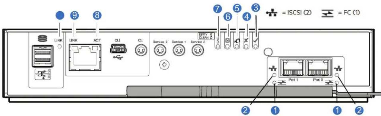
Figure 45 CNC (FC and 10GbE SFPs) Controller LEDs
LED Description Definition
Host 4/8/16Gb FC ^1 Link Off — No link detected.
1 Status/Link Activity Green — The port is connected and the link is up. Blinking green — The link has I/O or replication activity.
2 Host 10GbE iSCSI ^2,3 Off — No link detected. Link Status/Link Green — The port is connected and the link is up. Activity Blinking green — The link has I/O or replication activity.
3 OK Green — The controller is operating normally. Blinking green — System is booting. Off — The controller module is not OK, or is powered off.
4 Fault Off — The controller is operating normally. Amber — A fault has been detected or a service action is required. Blinking amber — Hardware-controlled power-up or a cache flush or restore error.
5 OK to Remove Off — The controller is not prepared for removal. Blue — The controller module is prepared for removal.
6 Identity White — The controller module is being identified.
7 Cache Status Green — Cache is dirty (contains unwritten data) and operation is normal. The unwritten information can be log or debug data that remains in the cache, so a Green cache status LED does not, by itself, indicate that any user data is at risk or that any action is necessary. Off — In a working controller, cache is clean (contains no unwritten data). This is an occasional condition that occurs while the system is booting. Blinking green — A CompactFlash flush or cache self-refresh is in progress, indicating cache activity.
8 Network Port Activity Off — The Ethernet link is not established, or the link is down. Status ^5 Green — The Ethernet link is up (applies to all negotiated link speeds).
9 Network Port Link Off — Link is up at 10/100base-T negotiated speeds. Speed ^4 Amber — Link is up and negotiated at 1000base-T.
10 Expansion Port Status Off — The port is empty or the link is down. Green — The port is connected and the link is up.
- ^1 When in FC mode, the SFPs must be qualified 8Gb or 16Gb fiber optic option.
- A 16Gb/s SFP can run at 16Gb/s, 8Gb/s, 4Gb/s, or auto-negotiate its link speed.
- An 8Gb/s SFP can run at 8Gb/s, 4Gb/s, or auto-negotiate its link speed.
- ^2 When in 10GbE iSCSI mode, the SFPs must be a qualified 10GbE iSCSI optic option.
- ^3 When powering up and booting, iSCSI LEDs will be on/blinking momentarily, then they will switch to the mode of operation.
• 4 When port is down, both LEDs are off.
CNC iSCSI Controller (2-Port 1Gb RJ-45 SFPs) and LED
Figure 48 provides an illustration of the CNC iSCSI controller (2-port 1Gb RJ-45 SFPs) and LEDs for the 2U12, 2U24, and 5U84 chassis.
NOTE: This CNC controller is used in the QXS-312 12G and QXS-324 12G.
Figure 46 CNC iSCSI Controller LEDs
LED Description Definition
1 FC SFP: not used in this The FC SFP is not shown in this example. example ^1
2 Host 1GbE iSCSI ^2,3 Off — No link detected. Link Status/Link Green — The port is connected and the link is up. Activity Blinking green — The link has I/O or replication activity.
3 OK Green — The controller is operating normally. Blinking green — System is booting. Off — The controller module is not OK, or is powered off.
4 Fault Off — The controller is operating normally. Amber — A fault has been detected or a service action is required. Blinking amber — Hardware-controlled power-up or a cache flush or restore error.
5 OK to Remove Off — The controller is not prepared for removal.
Blue — The controller module is prepared for removal.
6 Identity White — The controller module is being identified.
7 Cache Status Green — Cache is dirty (contains unwritten data) and operation is normal. The unwritten information can be log or debug data that remains in the cache, so a Green cache status LED does not, by itself, indicate that any user data is at risk or that any action is necessary.
Off — In a working controller, cache is clean (contains no unwritten data). This is an occasional condition that occurs while the system is booting.
Blinking green — A CompactFlash flush or cache self-refresh is in progress, indicating cache activity.
8 Network Port Activity Off — The Ethernet link is not established, or the link is down.
Status ^4 Green — The Ethernet link is up (applies to all negotiated link speeds).
9 Network Port Link Off — Link is up at 10/100base-T negotiated speeds.
Speed ^5 Amber — Link is up and negotiated at 1000base-T.
10 Expansion Port Status Off — The port is empty or the link is down.
Green — The port is connected and the link is up.
- ^1 When in FC mode, the SFPs must be qualified 8Gb or 16Gb fiber optic option.
- A 16Gb/s SFP can run at 16Gb/s, 8Gb/s, 4Gb/s, or auto-negotiate its link speed.
- An 8Gb/s SFP can run at 8Gb/s, 4Gb/s, or auto-negotiate its link speed.
- ^2 When in 10GbE iSCSI mode, the SFPs must be a qualified 10GbE iSCSI optic option.
- ^3 When powering up and booting, iSCSI LEDs will be on/blinking momentarily, then they will switch to the mode of operation.
• ^4 When port is down, both LEDs are off.
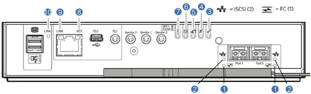
CNC Controller (4-Port FC and 10GbE SFPs) and LED
Figure 47 provides an illustration of the CNC controller (4-port FC and 10GbE SFPs) and LEDs for the 2U12, 2U24, and 5U84 chassis.
NOTE: This CNC controller is used in the QXS-412 12G, QXS-424 12G, and QXS-484 12G.
Figure 47 CNC (FC and 10GbE SFPs) Controller LEDs
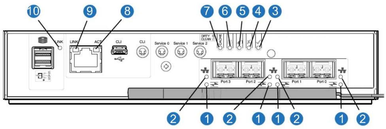
LED Description Definition
Host 4/8/16Gb FC ^1 Link Off — No link detected.
1 Status/Link Activity Green — The port is connected and the link is up. Blinking green — The link has I/O or replication activity.
2 Host 10GbE iSCSI ^2,3 Off — No link detected.
Link Status/Link Green — The port is connected and the link is up.
Activity Blinking green — The link has I/O or replication activity.
3 OK Green — The controller is operating normally. Blinking green — System is booting. Off — The controller module is not OK, or is powered off.
4 Fault Off — The controller is operating normally. Amber — A fault has been detected or a service action is required. Blinking amber — Hardware-controlled power-up or a cache flush or restore error.
5 OK to Remove Off — The controller is not prepared for removal. Blue — The controller module is prepared for removal.
6 Identity White — The controller module is being identified.
7 Cache Status ^4 Green — Cache is dirty (contains unwritten data) and operation is normal. The unwritten information can be log or debug data that remains in the cache, so a Green cache status LED does not, by itself, indicate that any user data is at risk or that any action is necessary. Off — In a working controller, cache is clean (contains no unwritten data). This is an occasional condition that occurs while the system is booting. Blinking green — A CompactFlash flush or cache self-refresh is in progress, indicating cache activity.
8 Network Port Activity Off — The Ethernet link is not established, or the link is down. Status ^5 Green — The Ethernet link is up (applies to all negotiated link speeds).
9 Network Port Link Off — Link is up at 10/100base-T negotiated speeds. Speed ^5 Amber — Link is up and negotiated at 1000base-T.
10 Expansion Port Status Off — The port is empty or the link is down. Green — The port is connected and the link is up.
- ^1 When in FC mode, the SFPs must be qualified 8Gb or 16Gb fiber optic option.
- A 16Gb/s SFP can run at 16Gb/s, 8Gb/s, 4Gb/s, or auto-negotiate its link speed.
- An 8Gb/s SFP can run at 8Gb/s, 4Gb/s, or auto-negotiate its link speed.
- ^2 When in 10GbE iSCSI mode, the SFPs must be a qualified 10GbE iSCSI optic option.
- ^3 When powering up and booting, iSCSI LEDs will be on/blinking momentarily, then they will switch to the mode of operation.
- ^4 Cache Status LED supports power on behavior and operational (cache status) behavior.
- ^5 When port is down, both LEDs are off.
CNC iSCSI Controller (4-Port 1Gb RJ-45 SFPs) and LED
Figure 48 provides an illustration of the CNC iSCSI controller (4-port 1Gb RJ-45 SFPs) and LEDs for the 2U12, 2U24, and 5U84 chassis.
Figure 48 CNC iSCSI Controller LEDs
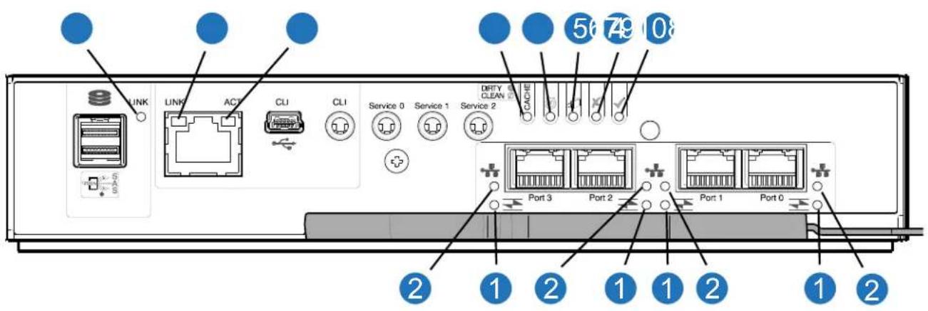
LED Description Definition
1 FC SFP: not used in this The FC SFP is not shown in this example. example ^1
2 Host 1GbE iSCSI ^2,3 Off — No link detected.
Link Status/Link Green — The port is connected and the link is up.
Activity Blinking green — The link has I/O or replication activity.
3 OK Green — The controller is operating normally.
Blinking green — System is booting.
Off — The controller module is not OK, or is powered off.
4 Fault Off — The controller is operating normally.
Amber — A fault has been detected or a service action is required.
Blinking amber — Hardware-controlled power-up or a cache flush or restore error.
5 OK to Remove Off — The controller is not prepared for removal.
Blue — The controller module is prepared for removal.
6 Identity White — The controller module is being identified.
7 Cache Status ^4 Green — Cache is dirty (contains unwritten data) and operation is normal. The unwritten information can be log or debug data that remains in the cache, so a Green cache status LED does not, by itself, indicate that any user data is at risk or that any action is necessary.
Off — In a working controller, cache is clean (contains no unwritten data). This is an occasional condition that occurs while the system is booting.
Blinking green — A CompactFlash flush or cache self-refresh is in progress, indicating cache activity.
8 Network Port Activity Off — The Ethernet link is not established, or the link is down. Status ^5 Green — The Ethernet link is up (applies to all negotiated link speeds).
9 Network Port Link Off — Link is up at 10/100base-T negotiated speeds. Speed ^5 Amber — Link is up and negotiated at 1000base-T.
10 Expansion Port Status Off — The port is empty or the link is down. Green — The port is connected and the link is up.
- ^1 When in FC mode, the SFPs must be qualified 8Gb or 16Gb fiber optic option.
- A 16Gb/s SFP can run at 16Gb/s, 8Gb/s, 4Gb/s, or auto-negotiate its link speed.
-
An 8Gb/s SFP can run at 8Gb/s, 4Gb/s, or auto-negotiate its link speed.
-
^2 When in 10GbE iSCSI mode, the SFPs must be a qualified 10GbE iSCSI optic option.
- ^3 When powering up and booting, iSCSI LEDs will be on/ blinking momentarily, then they will switch to the mode of operation.
- ^4 Cache Status LED supports power on behavior and operational (cache status) behavior.
- ^5 When port is down, both LEDs are off.
Cache Overview and Status LED Details
This section provides the following information:
- Cache Overview
• Power On/Off Behavior - Cache Status Behavior
Cache Overview
To enable faster data access from disk storage, the following types of caching are performed:
- Write-back caching.
- The controller writes user data into the cache memory in the controller module rather than directly to the disks.
- Later, when the storage system is either idle or aging—and continuing to receive new I/O data—the controller writes the data to the disks.
- Read-ahead caching.
- The controller detects sequential data access, reads ahead into the next sequence of data—based upon settings—and stores the data in the read-ahead cache.
- Then, if the next read access is for cached data, the controller immediately loads the data into the system memory, avoiding the latency of a disk access.
TIP: See the QXS 12G Disk Management Utility User Guide for more information about cache options and settings.
Power On/Off Behavior
The storage chassis unified complex programmable logic device (CPLD) provides integrated Power Reset Management (PRM) functions. During power on, discrete sequencing for power on display states of internal components is reflected by blinking patterns displayed by the Cache Status LED. Table4 provides the cache status LED behavior.
Table 4 Cache Status LED – Power On Behavior
| Item Display states reported by Cache Status LED during power on sequence | ||||||||
| D i | s | p | l | a | y | s | t | a |
Table 4 Cache Status LED – Power On Behavior
| Item | Display states reported by Cache Status LED during power on sequence | |||||||
| Component VP | SC SAS BE A | ASIC Host Bo | ot Normal R | Reset | ||||
| Blink pattern O | 1/Off 7 On | 2/Off 6 On | 3/Off 5 On 4 | /Off 4 On 5 | /Off 3 On 6/ | /Off 2 Solid/On | Steady | |
NOTE: Once the chassis has completed the power on sequence, the Cache Status LED displays Solid/On (Normal), before assuming the operating state for cache purposes.
Cache Status Behavior
If the LED is blinking evenly, a cache flush is in progress. When a controller module loses power and write cache is dirty (contains data that has not been written to drives), the supercapacitor pack provides backup power to flush (copy) data from write cache to CompactFlash memory. When cache flush is complete, the cache transitions into self-refresh mode.
If the LED is blinking momentarily slowly, the cache is in a self-refresh mode. In self-refresh mode, if primary power is restored before the backup power is depleted (3–30 minutes, depending on various factors), the system boots, finds data preserved in cache, and writes it to drives. This means the system can be operational within 30 seconds, and before the typical host I/O time-out of 60 seconds, at which point system failure would cause host-application failure. If primary power is restored after the backup power is depleted, the system boots and restores data to cache from CompactFlash, which can take about 90 seconds.
The cache flush and self-refresh mechanism is an important data protection feature; essentially four copies of user data are preserved: one in controller cache and one in CompactFlash of each controller. The Cache Status LED illuminates solid green during the boot-up process. This behavior indicates the cache is logging all POSTs, which will be flushed to the CompactFlash the next time the controller shuts down.
IMPORTANT: If the Cache Status LED illuminates solid green—and you wish to shut down the controller—do so from the user interface, so unwritten data can be flushed to CompactFlash.
Controller Failure/Single-Controller Operational
Cache memory is flushed to CompactFlash in the case of a controller failure or power loss. During the write to CompactFlash process, only the components needed to write the cache to the CompactFlash are powered by the supercapacitor.
This process typically takes 60 seconds per 1Gbyte of cache. After the cache is copied to CompactFlash, the remaining power left in the supercapacitor is used to refresh the cache memory. While the cache is being maintained by the supercapacitor, the Cache Status LED blinks at a rate of 1/10 second on and 9/10 second off.
If the controller has failed or does not start, is the Cache Status LED on/blinking?
Table 5 Controller Failure/Single-Controller Operational
| Answer Action | |
| No, the Cache LED status is off, and the controller does not boot. | If the problem persists, replace the controller module. |
| No, the Cache Status LED is off, and the controller boots. | The system has flushed data to disks. If the problem persists, replace the controller module. |
| Yes, at a strobe 1:10 rate - 1 Hz, and the controller does not boot. | You may need to replace the controller module. |
| Yes, at a strobe 1:10 rate - 1 Hz, and the controller boots. | The system is flushing data to CompactFlash. If the problem persists, replace the controller module. |
| Yes, at a blink 1:1 rate - 2 Hz, and the controller does not boot. | You may need to replace the controller module. |
| Yes, at a blink 1:1 rate - 1 Hz, and the controller boots. | The system is in self-refresh mode. If the problem persists, replace the controller module. |
12Gb/s Expansion IOM
If optional expansion chassis have been cabled to add storage, the supported chassis are configured with dual expansion IOMs.
Figure 49 provides an illustration of the expansion IOM and LEDs for the 2U12, 2U24, and 5U84 chassis.
Figure 49 Expansion IOM LEDs
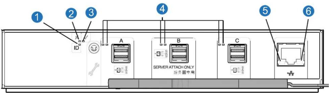
LED Description Definition
1 Identity Blue — The IOM is being identified.
2 Fault Off — The IOM is operating normally.
Amber — A fault has been detected or a service action is required.
3 OK Green — The expansion module is operating normally.
Blinking green — System is booting.
Off — The expansion module is powered off.
4 HD mini-SAS connector LEDs See Table 6 for Activity (Green) and Fault (Amber) LED states. (A/B/C)
5 Ethernet Port Link/Active Status (Left) Not used in this configuration.
6 Ethernet Port Link Speed (Right) Not used in this configuration.
Table 6 provides companion data for Figure 49 above relative to LED states for A/B/C SAS port expansion.
Table 6 IOM LED Activity States
| Condition Activity (Green) Fault (Amber) | ||
| No cable present Off Off | ||
| Cable present: all links up/no activity On Off | ||
| Cable present: all links up/with aggregate port activity Blinking | Off | |
| Critical fault: Any fault causing operation of the cable to cease or fail to start (e.g., over current trip). | Off On | |
| Non-critical fault: any fault that does not cause the connection to cease operation (e.g., not all links are established; over temperature). | Blinking | Blinking: 1s on/1s off |
IMPORTANT: RAID and expansion chassis configurations:
- When the expansion IOM shown above (Figure 49) is used with the QXS-412 12G, QXS-424 12G, and QXS-484 12G system controller modules for adding storage, its middle HD mini-SAS expansion port ("B") is disabled by the firmware.
- The Ethernet port on the expansion IOM is not used in RAID and expansion chassis configurations, and is disabled.
Drive Modules
The QXS-312 12G, QXS-324 12G, QXS-412 12G, QXS-424 12G, and QXS-484 12G systems support different drive modules for use in 2U and 5U chassis. The drive modules used in 2U chassis are referred to as drive carrier modules, whereas those used in 5U chassis are referred to as a Disk Drive in Carrier (DDIC).
Drive Carrier Module in 2U Chassis
The drive carrier module comprises a hard disk held by a carrier.
- Each 2U12 drive slot holds a single low profile 1.0-inch high, 3.5-inch form factor drive in its carrier.
• The drives are horizontal.
- The 2U12 chassis accommodates 3.5" SAS and 3.5" SATA drives.
- A special interposer is required for SATA drives (included with the SATA drive and its carrier when purchased).
- Each 2U24 drive slot holds a single low profile 5/8-inch high, 2.5-inch form factor disk drive in its carrier.
• The drives are vertical.
- The 2U24 chassis accommodates 2.5" SAS or SATA drives.
- A special interposer is required for SATA drives (included with the SATA drive and its carrier when purchased).
The carriers have mounting locations for:
- Direct dock SAS drives.
- A sheet steel carrier holds each drive, which provides thermal conduction, radio frequency, and electro-magnetic induction protection, and physically protects the drive.
The front cap also has an ergonomic handle which gives the following functions:
- Secure location of the carrier into and out of drive slots.
- Positive spring-loading of the drive/midplane connector.
• The carrier can use this interface:
- Dual path direct dock Serial Attached SCSI.
Populating 2U12 Chassis with Drives
The 2U12 chassis ships with drives installed. Please review these rules:
• The minimum number of drives supported by the chassis is 1.
- Hard disk drives (HDD) and solid state drives (SDD) can be mixed in the chassis.
NOTE: If the chassis has no drives installed, always install the first drive into slot 0, and then populate slots 1-11 sequentially with any additional drives.
Integers on the drives indicate drive slot numbering sequence (0-11). Figure 50 provides a front view of the 2U12-drive chassis fully populated with drives.
Figure 50 2U12-Drive Chassis Front View

Populating 2U24 Chassis with Drives
The 2U24 chassis ships with drives installed. Please review these rules:
• The minimum number of drives supported by the chassis is 1.
- Hard disk drives (HDD) and solid state drives (SDD) can be mixed in the chassis.
NOTE: If the chassis has no drives installed, always install the first drive into slot 0, and then populate slots 1-23 sequentially with any additional drives.
Integers on the drives indicate drive slot numbering sequence (0-23). Figure 51 provides a front view of the 2U24-drive chassis fully populated with drives.
Figure 51 2U24-Drive Chassis Front View

NOTE: Diametric pictorial views of supported drive carriers are provided in the following illustrations. Modules are shown oriented for insertion into drive slots located on the chassis front panel.
LFF 3.5" Drive Carrier Module (SAS Drive)
Figure 52 provides an illustration of the dual path LFF 3.5" drive carrier module for the 2U12 chassis.
Figure 52 LFF 3.5" Drive Carrier Module (SAS Drive)
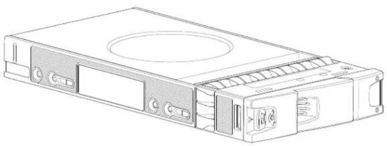
natural_image
Line drawing of a computer drive chassis with ports and connectors (no text or symbols)SFF 2.5" Drive Carrier Module (SAS Drive)
Figure 53 provides an illustration of the dual path SFF 2.5" drive carrier module for the 2U24 chassis.
Figure 53 SFF 2.5" Drive Carrier Module (SAS Drive)
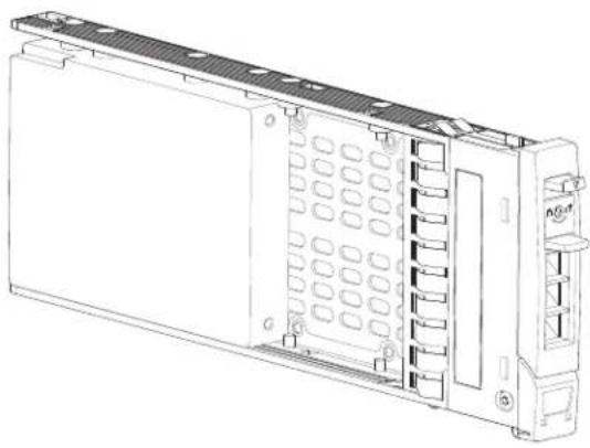
natural_image
Technical line drawing of a server rack unit with ventilation slots and ports (no text or symbols)Drive Status Indicators
Green and amber LEDs on the front of each drive carrier module indicate drive status. The SEP controls these LEDs.
Drive Blanks
Drive blanks, also known as dummy drive carrier modules, are provided in 3.5" (2U12) and 2.5" (2U24) form factors. They must be installed in empty disk drive slots to create a balanced air flow.
Figure 54 provides an illustration of the 3.5" drive blank for the 2U12 chassis and the 2.5" drive blank for the 2U24 chassis
Figure 54 2.5" and 3.5" Drive Blank
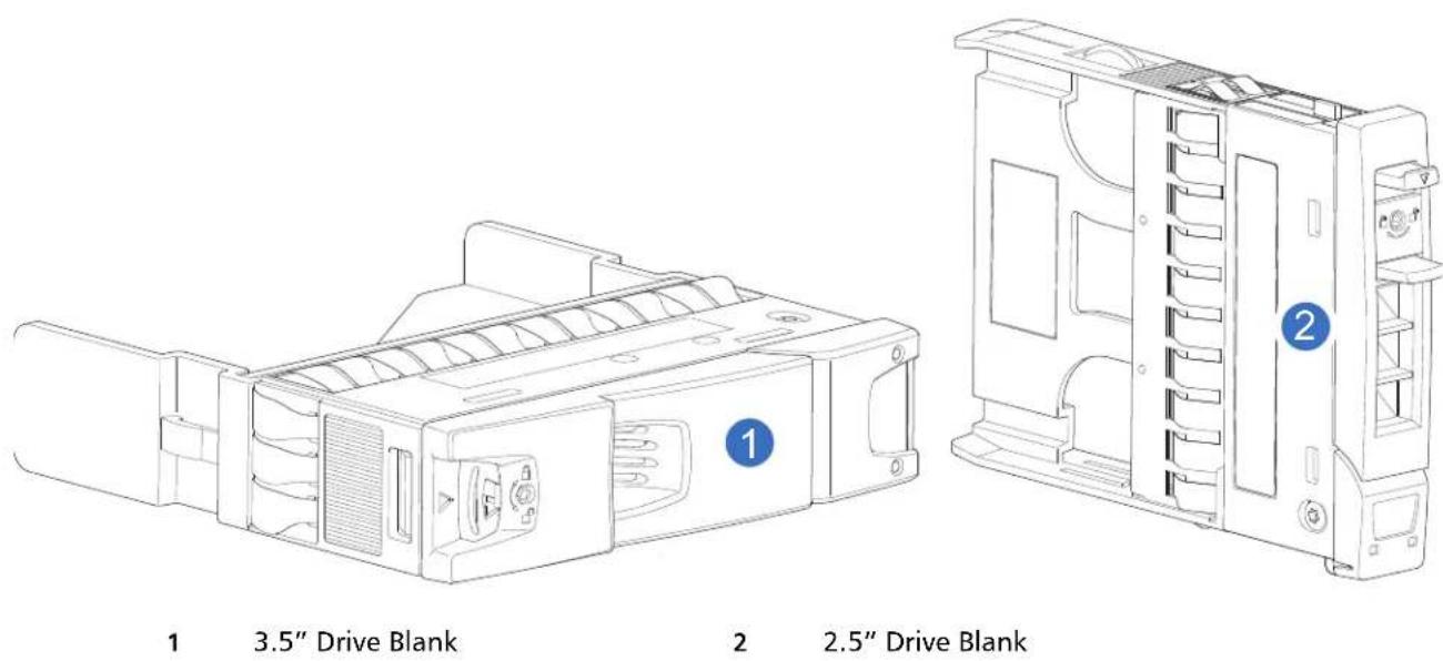
DDIC in 5U chassis
Each drive is housed in a carrier that enables secure insertion of the drive into the drawer with the appropriate SAS carrier transition card.
DDIC with 3.5" Drive
Figure 55 shows a DDIC with a 3.5" drive for the 5U84 chassis.
Figure 55 DDIC with 3.5" Drive
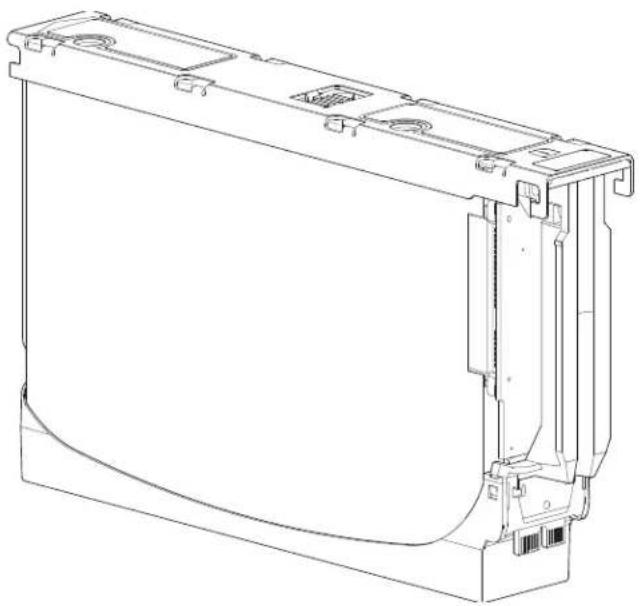
natural_image
Technical line drawing of a mechanical component with mounting brackets and internal features (no text or symbols)DDIC with Adapter and 2.5" Drive
Figure 56 shows a DDIC with adapter and 2.5" drive for the 5U84 chassis.
Figure 56 DDIC with Adapter and 2.5" Drive
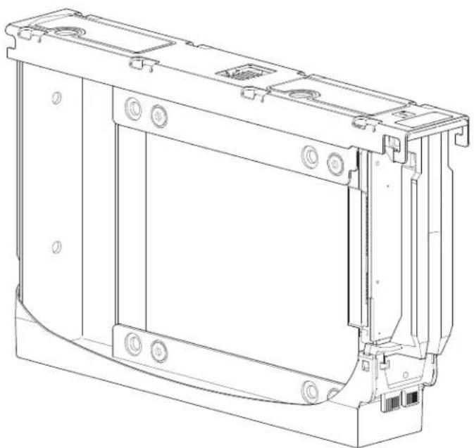
natural_image
Technical line drawing of a mechanical housing or enclosure component (no text or symbols)The DDIC features a latch button (center of top view) and a slide latch with arrow label (left of latch button). These features allow you to install and secure the DDIC into the drive slot within the drawer. They also allow you to disengage the DDIC from its slot, and remove it from the drawer. The DDIC features a single Drive Fault LED (top view on right), which illuminates amber when the disk has a fault.
Populating Drawers with DDICs
The 5U84 chassis does not ship with DDICs installed. Please review these rules:
• The minimum number of drives supported by the chassis is 14.
- DDICs must be added to drive slots in rows (14 drives at a time).
- Beginning at the front of the drawer(s), install DDICs consecutively by number, and alternately between the top drawer and the bottom drawer.
- Namely, install first at slots 0 through 13 in the top drawer, and then 42 through 55 in the bottom drawer.
• After that, install slots 14 through 27, and so on.
- The number of populated rows must not differ by more than one row between the top and bottom drawers.
- Hard disk drives (HDD) and solid state drives (SDD) can be mixed in the same drawer.
- HDDs installed in the same row should have the same rotational speed.
- Although DDICs holding 3.5" disks can be intermixed with DDICs holding 2.5" disks within the chassis, each row should be populated with drives of the same form factor (all LFF or all SFF).
NOTE: For additional information, see Populating 5U84 Drawers on page 193 within 5U84 Chassis CRU Replacement on page 188.
Figure 57 shows a 5U84 chassis drawer fully populated with DDICs (42 drives).
Figure 57 5U84 Chassis Drawer Fully Populated (42 Drives)
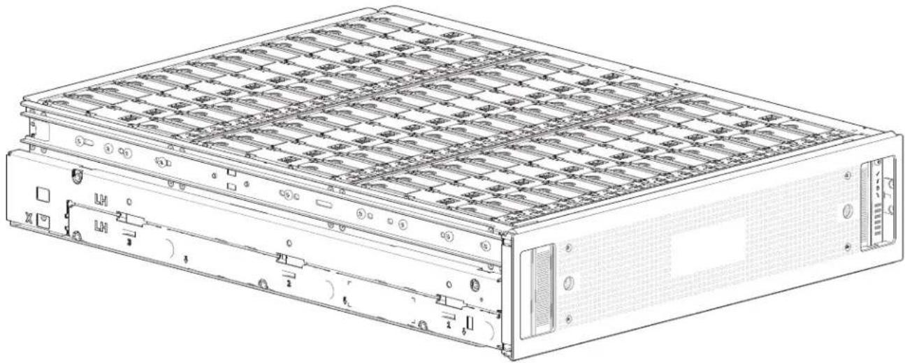
natural_image
Technical line drawing of a server rack with multiple drive bays and ventilation slots (no text or labels)Chassis Management
Controller modules actively manage the chassis. Each controller has a SAS expander with its own storage enclosure processor (SEP) that provides a SES target for a host to interface to through the ANSI SES Standard. If one of these controllers fails, the other module will continue to operate.
Refer to the controller's specification or the SES Interface specification for definitions of the module's functions and its SES control.
Management Interfaces
Upon completing the hardware installation, you can access the controller module's web-based management interface—disk management utility (GUI)—to configure, monitor, and manage the storage system. See also "Accessing the disk management utility".
The controller module also provides a CLI in support of command entry and scripting.

natural_image
Abstract pattern of blue squares arranged in a grid on white background (no text or symbols)Chapter 3
Installation
This chapter provides installation information for the following QXS 12G systems:
• QXS-312 12G: 12-Drive (2-Port: FC or iSCSI)
• QXS-324 12G: 24-Drive (2-Port: FC or iSCSI)
• QXS-412 12G: 12-Drive (4-Port: FC or iSCSI)
• QXS-424 12G: 24-Drive (4-Port: FC or iSCSI)
• QXS-484 12G: 84-Drive (4-Port: FC or iSCSI)
Installation Checklist
This section shows how to plan for and successfully install of your system into an industry standard 19-inch rack cabinet.
NOTE: QXS 12G systems bundled with Xcellis Workflow Director systems should not use this "Installation Checklist" for initial installations. Use the Quick Start shipped in the Xcellis Workflow Director system boxes.
CAUTION: To install the system, use only the power cords supplied, or power cables that match the specification quoted in AC Power Cords on page 221.
Table 7 outlines the steps required to install the chassis, and initially configure and provision the storage system. To ensure successful installation, perform the tasks in the order presented.
Table 7 Installation Checklist
| Step Task Where to Find Procedure | ||
| 1 | Unpack the chassis. | See Unpacking Chassis on page 59. |
| 2 Install the RAID chassis and optional expansion chassis in the rack. ^1 | • See Required Tools on page 61.• See Requirements for rackmount installation on page 62.• See Installing 2U Chassis on page 62.• See Installing 5U Chassis on page 64. | |
| 3 Note: | 2U12 and 2U24 Chassis: ship with drives installed. | For additional information on the 2U12 and 2U24 Chassis, see:Full Disk Encryption (FDE) on page 65.Populating 2U12 Chassis with Drives on page 49 (if required).Populating 2U24 Chassis with Drives on page 50 (if required). |
| 5U84 Chassis: populate drawers with drives (DDIC–disk in drive carrier).NOTE: Drives ship in two separate boxes (42 drives in each box). | • See Populating Drawers with DDICs on page 53.• See Installing a 5U84 DDIC on page 192. | |
| 4 | Connect power cords. | See Power Cord Connection on page 71. |
| 5 | Test chassis connectivity. | See Testing Chassis Connections on page 72. |
| 6 For CNC models, verify the host interface protocol setting (not necessary for SAS models). | • See CNC Technology on page 73.• The CNC controllers allow for setting the host interface protocol for qualified SFP options.• See Change CNC Port Mode on page 98. | |
| 7 | Install required host software. | See Host System Requirements on page 72. |
| 8 | Connect hosts. ^2 | See Host Connection on page 76. |
| 9 | Connect remote management hosts. | See Connecting Management Host to Network on page 83. |
| 10 | Obtain IP values and set network port IP properties on the RAID chassis. | • See Obtaining IP Values and System Settings on page 85 using the Disk Management Utility (GUI).• For USB CLI port and cable see USB Device Connection on page 223. |
| 11 | Perform initial configuration tasks: ^3 | Topics below correspond to bullets at left: |
| Sign-in to the web-browser interface to access the application GUI. | See the “Getting Started” chapter in | |
| Verify firmware revisions and update if necessary. | See Updating Firmware on page 84.Also see the same topic in the . | |
| Initially configure and provision the system using the disk management utility (GUI). | See the topics about configuring the system and provisioning (One Button Configuration: OBC) the system in the . | |
| 12 | 2U12 and 2U24 Chassis: Install bezel. | See Installing a 2U Bezel on page 165. |
| 5U84 Chassis: The two bezels are installed at the factory. The bezels can be replaced if damaged. | See Removing a 5U84 Bezel on page 195 and Installing a 5U84 Bezel on page 197. | |
- ^1 The environment in which the chassis operates must be dust-free to ensure adequate airflow.
• ^2 For more information about hosts, see the About hosts topic in the .
- ^3 The is introduced in Accessing Disk Management Utility (GUI) on page 112. See the or online help for additional information.
Planning for Installation
Before beginning the chassis installation, familiarize yourself with the system configuration requirements. The figures listed below show the locations for each plug-in module (CRU):
• 2U12 front panel: see 2U12-Drive Chassis Front View on page 16
• 2U24 front panel: see 2U24-Drive Chassis Front View on page 16
• 2U RAID chassis rear panel:
• 4-host port controllers
• See QXS-412 12G, QXS-424 12G, and QXS-484 12G RAID Chassis Rear View (4-Host Port Controllers) on page 18
• 2U RAID chassis rear panel:
- 2-host port controllers
• See QXS-312 12G and QXS-324 12G RAID Chassis Rear View (2-Host Port Controllers) on page 16
- 2U expansion chassis rear panel: see 2U12-Drive/2U24-Drive Expansion Chassis Rear View on page 19
- 5U front panel: see 5U Chassis Drive Slots View on page 23
- 5U RAID chassis rear panel: see 5U84 RAID Chassis (Rear View/Two CNC Controllers) on page 24
- 5U expansion chassis rear panel: see 5U84 Expansion Chassis (Rear View) on page 26
IMPORTANT: Installation work should be performed by qualified service personnel.
Table 8 provides storage system configuration information.
Table 8 Storage System Configuration
| Module/CRU Location | Description | |
| Drive carrier module | 2U front panel | All drive slots must hold either a drive carrier or dummy drive carrier module. Empty slots are not allowed. At least one drive must be installed. |
| DDIC 5U front panel | Maximum 84 disks are installed (42 disks per drawer).Minimum 14 disks are required. Follow drawer population rules.See Populating Drawers with DDICs on page 53. | |
| PSU 2U rear panel Two | PSUs provide full power redundancy, allowing the system to continue to operate while a faulty PSU is replaced. | |
| PSU 5U rear panel Two | PSUs provide full power redundancy, allowing the system to continue to operate while a faulty PSU is replaced. | |
| Fan 5U rear panel Five fans provide airflow circulation, maintaining all system components below the maximum temperature allowed. | ||
| RAID Controller | Rear panel | Two RAID controllers must be installed for this configuration (RAID chassis). |
| Expansion IOM | Rear panel | Two expansion IOMs must be installed for this configuration (expansion chassis). |
NOTE: Although different drive modules and rear panel CRUs are used by the different chassis form factors, whether used for RAID chassis or expansion chassis configuration, the RAID controllers and expansion IOMs are common across 2U and 5U chassis.
Preparing for Installation
NOTE: Chassis configurations:
• 2U RAID chassis are delivered without drives installed (RAID controllers and PSUs are installed).
- 2U expansion chassis are delivered without drives installed (expansion IOMs and PSUs are installed).
- 5U RAID chassis are delivered:
- Without drives installed within the drawers.
- Drives ship in a 42-drive pack (two each 42-drive packs for a total of 84 drives).
- RAID controllers, fans, and PSUs are installed within the chassis.
- 5U expansion chassis are delivered:
- Without drives installed in the drawers.
- Drives ship in a 42-drive pack (two each 42-drive packs for a total of 84 drives).
- Expansion IOMs, fans, and PSUs are installed within the chassis.
CAUTION: Lifting chassis:
- A 2U chassis—together with all its component parts—is too heavy for one person to lift and install into the rack cabinet. Two people are required to safely move a 2U chassis.
- A 5U chassis—delivered without DDICs installed—requires four people to lift it from the box. A suitable mechanical lift is required to hoist the chassis for positioning in the rack.
Make sure you wear an effective anti-static wrist or ankle strap and obey conventional ESD precautions when touching modules and components. Do not touch midplane, motherboard, or module connectors. See also ESD Precautions on page 163. This section provides important preparation requirements and handling procedures for use during product installation.
Preparing Site and Host Server
Before beginning the chassis installation, verify that the site where you will install your storage system has the following:
- A standard AC power supply from a independent source or a rack power distribution unit with an Uninterruptible Power Supply (UPS).
- A host computer configured with the appropriate software, BIOS, and drives. Contact your supplier for the correct software configurations.
Before installing the chassis, verify the existence of the following:
- Qualified cable options for host connection
Depending upon the controller module: FC or iSCSI HBA and appropriate switches (if used)
• One power cord per PSU
• Rail kit (for rack installation)
Please refer to your supplier for a list of qualified accessories for use with the chassis. The accessories box contains the power cords and other accessories.
Unpacking Chassis
NOTE: The bezel assembly and applicable cables and/or power cords are shipped in separate boxes.
Unpack the chassis as follows:
1 Examine the packaging for crushes, cuts, water damage, or any other evidence of mishandling during transit.
- If you suspect that damage has happened, photograph the package before opening, for possible future reference.
- Retain original packaging materials for use with returns.
2 The unpacking sequence pertaining to 2U chassis is shown in Figure 58.
Figure 58 Unpack 2U Chassis (2U24 Chassis Shown)
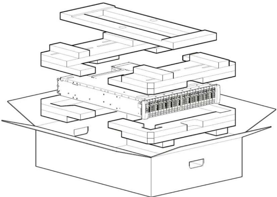
natural_image
Isometric line drawing of a multi-level mechanical or architectural assembly inside an open box, showing structural layers and components (no text or symbols)The 2U chassis are supplied with the midplane PCB, PSUs, drives, and RAID controllers and/or expansion IOMs installed. For information about plug-in module replacement, see "Module removal and replacement". Drive blanks must be installed in unused drive slots.
3 The unpacking procedure pertaining to the 5U84 is shown in Figure 59.
CAUTION: The chassis does not include DDICs, but all rear panel modules are installed.
• This partially-populated chassis is quite heavy: 64 kg (142 lb).
- Verify that each strap is securely wrapped and buckled.
- Four people are required to lift the 5U84 from the box.
Figure 59 Unpack 5U84 Chassis
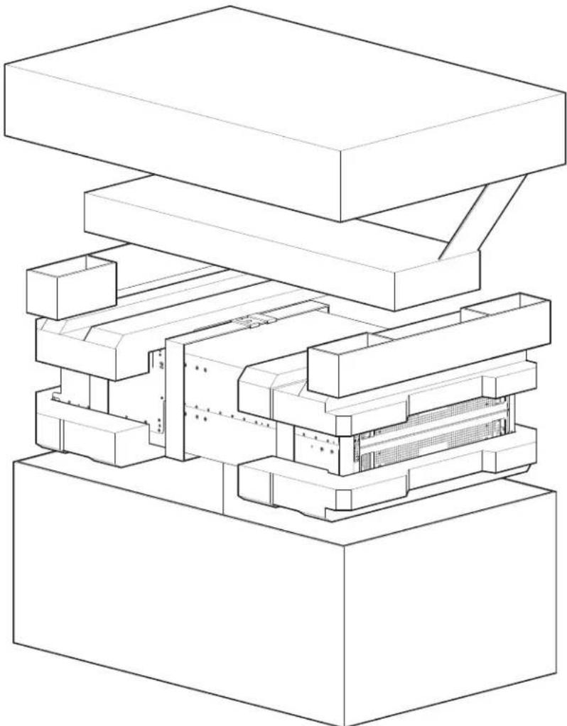
natural_image
Technical line drawing of a mechanical assembly with stacked components (no text or symbols)The railkit and accessories box is located immediately below the box lid (Figure 58 and Figure 59).
CAUTION: With four persons—positioned one at each corner of the chassis—grip the straps securely by the loops, and lift the chassis out of the box, using appropriate lifting technique. Place the chassis in a static-protected area.
NOTE: If your product model uses CNC ports for FC or iSCSI, you must locate and install the SFPs. See also Locate SFP Transceivers on page 229.
Required Tools
Required tools include:
- Flat blade screwdriver
- Torx T10/T20 bits for locks and select CRU replacement
Requirements for rackmount installation
You can install the chassis in an industry standard 19-inch cabinet capable of holding 2U form factors.
- Minimum depth: 707 mm (27.83") from rack posts to maximum extremity of chassis (includes rear panel cabling and cable bend radii).
- Weight:
- Up to 32 kg (71 lb), dependent upon configuration, per 2U chassis.
- Up to 128 kg (282 lb), dependent upon configuration, per 5U chassis.
- The rack should cause a maximum back pressure of 5 pascals (0.5 mm water gauge).
- Before you begin, ensure that you have adequate clearance in front of the rack for installing the rails.
Rackmount rail kit
Various sets of rack mounting rails are available for use in 19-inch rack cabinets. These rails have been designed and tested for the maximum chassis weight, and to make sure that multiple chassis may be installed without loss of space within the rack. Use of other mounting hardware may cause some loss of rack space. Contact your supplier to make sure suitable mounting rails are available for the rack you plan to use.
Installing 2U Chassis
Install the chassis as follows:
1 Remove the rack mounting rail kit from the accessories box, and examine for damage.
2 Use the following procedure to attach the rail kit brackets to the rack post as shown in Figure 60.
a Set the location pin at the rear of the rail into a rear rack post hole.
- Attach the bracket to the rear rack post: use the screws supplied, Callout 9 (11A screw).
- Leave the screws loose.
b Extend the rail to fit between the front and rear rack posts.
c Attach the bracket to the front rack post using the screws supplied, Callout 3 (11A screw). Leave the screws loose.
d Tighten the locking screw (Callout 7) located along the inside of the rear section of the rack bracket.
3 Repeat the above sequence of steps for the companion rail.
Figure 60 2U Secure Brackets to Rail
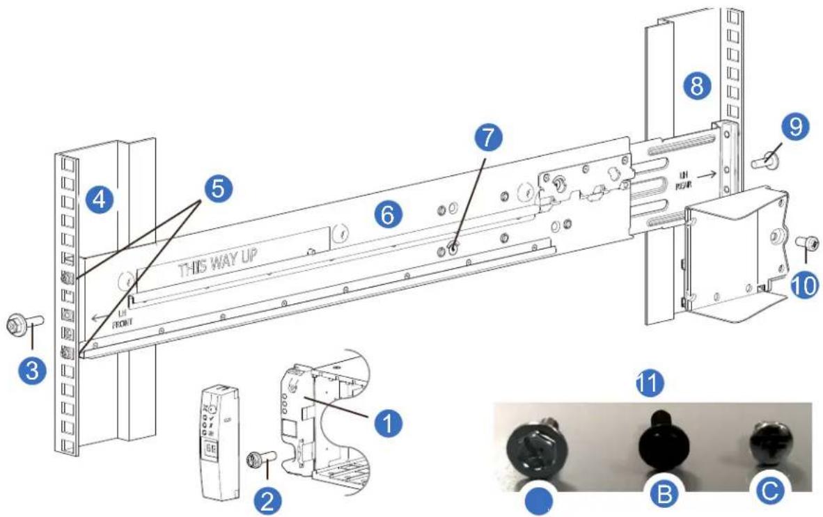
1 2U Left ear (ops panel cover exploded to show 2 Fastening screw: B left ear flange fastening screw)
3 Clamping screw (front): A 4 Front rack post: square hole
5 Rail location pins 6 Left hand (LH) rail
7 Locking screw 8 Rear rack post: square hole
9 Clamping screw (rear): A 10 2U Chassis fastening screw: C
11 Screws: Rail kit fasteners
4 Install the chassis into the rack:
a Lift the chassis and align it with the installed rack rails, taking care to ensure that the chassis remains level.
b Carefully insert the chassis into the rack rails and push fully in.
c Tighten the mounting screws, Callout 9 (11A screws) in the rear rail kit brackets.
d Slide the chassis forward until it reaches the hard stops—approximately 400 mm (15.75")—and tighten the mounting screws, Callout 3 (11A screws) in the front rail kit bracket.
e Return the chassis to the fully home position.
5 Install the 2u chassis fastening screw, Callout 10 (11C screw) to secure the chassis to the back of the rack.
Installing 5U Chassis
The 5U84 chassis is delivered without the disks installed. Due to the weight of the chassis, install the chassis into the rack without DDICs installed, and remove the rear panel CRUs to lighten the chassis weight.
The adjustment range of the rail kit from the inside of the front post to the inside of the rear post is 660mm – 840mm (26"-33"). This range suits a one meter deep rack within Rack Specification IEC 60297.
Install the chassis as follows:
1 To facilitate access, remove the doors from the cabinet.
2 Ensure that the pre-assembled rails are at their shortest length (refer to the reference label on the inside of the rail).
3 Locate/seat the rail location pins (callout 5) inside the front of the rack, and extend the length of the rail assembly to enable the rear location pins to locate/insert into the back of the rack (callout 7).
- Ensure the pins are fully located/seated in the square or round holes in the rack posts.
• See also Figure 61.
Figure 61 5U Secure Brackets to Rail
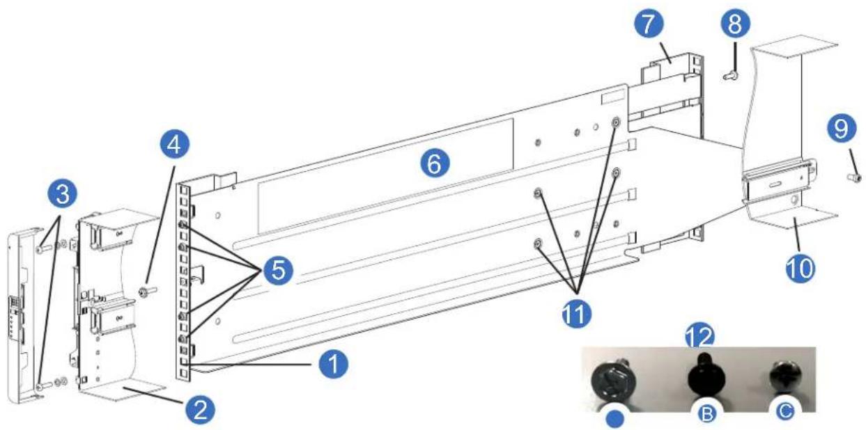
1 Front rack post: square hole 2 Front left portion 5U chassis (for reference)
3 Fastening screw: A 4 Clamping screw: B
5 Rail location pins 6 Left hand (LH) rail
7 Rear rack post: square hole 8 Clamping screw: B
9 Fastening screw: C 10 Rear left portion 5U chassis (for reference)
11 Middle slide locking screws 12 Screws: Rail kit fasteners
4 Fully tighten all clamping screws.
• Front: Callout 4 (screw 12B)
• Rear: Callout 8 (screw 12B)
5 Tighten the middle slide locking screws (callout 11).
6 Ensure the rear spacer clips (x4) are fitted to the edge of the rack post.
7 Slide the chassis fully home on its rails.
8 Fasten the front of the chassis using the chassis fastening screws, Callout 3 (screw 12A, x4) as shown in Figure 61.
9 Fix the rear of the chassis to the sliding bracket with the rear chassis fastening screws, Callout 9 (screw 12C).
CAUTION: Use only power cords supplied, or power cords that comply with the specifications in AC Power Cords on page 221.
CAUTION: Once the chassis is installed in the rack, dispose of the lifting straps.
Due to the difficulty in attaching the straps once the chassis is installed into the rack, the straps are not suitable for removing the chassis from the rack.
10 Reinsert all of the rear panel CRUs, and install all of the DDICs into the drawers accessed from the front panel per the following instructions:
• Install five fans Installing a 5U84 System Fan on page 204
• Install two PSUs Installing a 5U84 System PSU on page 202
- Installing two RAID controllers or expansion IOMs Installing a 5U84 RAID Controller or Expansion IOM on page 208
• Install all DDIC Installing a 5U84 DDIC on page 192
• See also:
• Accessing 5U84 Drawers on page 189
• Populating 5U84 Drawers on page 193
11 If you removed the cabinet doors, install them now.
Full Disk Encryption (FDE)
The Full Disk Encryption (FDE) feature available via the management interfaces requires use of self-encrypting drives (SED) which are also referred to as FDE-capable drive modules. When installing FDE-capable drive modules, follow the same procedures for installing drives that do not support FDE.
The procedures for using the FDE feature, such as securing the system, viewing drive FDE status, and clearing and importing keys are performed using the disk management utility (GUI) or CLI commands.
NOTE: When moving FDE-capable drive modules for a disk group, stop I/O to any volumes in the disk group before removing the drive modules.
Follow the procedures in "Module removal and replacement" for replacing drive modules relative to the chassis type (2U or 5U). Import the keys for the drives so that the drive content becomes available.
Federal Information Processing Standards (FIPS)
FIPS are U.S. government computer security standards that specify requirements for cryptography modules. FIPS is a widely recognized and demanded cert when it comes to government agencies and industry's subject to strict security compliance. FIPS certification is available on self-encrypting drives (SEDs).
Connecting RAID Chassis and Expansion Chassis
Use this section to connect the RAID chassis to the expansion chassis. Connecting/cabling suggestions are provided. The customer can select the applicable connecting/cabling best suited for their installation.
NOTE: Reverse cabling/straight-through cabling for the RAID chassis and expansion is provided. Reverse cabling is suggested because it provides redundancy (alternate path to access chassis).
Table 9 provides the RAID chassis system, drive form factor per chassis, and the number of expansion chassis supported in a RAID chassis and expansion chassis combination.
Table 9 RAID Chassis with Supported Expansion Chassis
| Drive Expansion Chassis | QXS-312 12G RAID Chassis Attach | QXS-412 12G RAID Chassis Attach | QXS-324 12G RAID Chassis Attach | QXS-424 12G RAID Chassis Attach | QXS-484 12G RAID Chassis Attach |
| Drive Form Factor Per Chassis | 12-drives (3.5" LFF) | 12-drives (3.5" LFF) | 24-drives (2.5" SFF) | 24-drives (2.5" SFF) | 84-drives (2.5" SFF or 3.5" LFF) |
| 2U12 Expansion Chassis | Up to 3 Up to 9 Up | p to 3 Up to 9 N/A | |||
| 2U24 Expansion Chassis | Up to 3 Up to 9 Up | p to 3 Up to 9 N/A | |||
| 5U84 Expansion Chassis | N/A Up to 3 N/A Up | p to 3 Up to 3 | |||
| Intermix 2U Expansion Chassis | Up to 3 Up to 9 Up | p to 3 Up to 9 N/A |
Note: The 2U12 and 2U24 expansion chassis can be intermixed. However, mixing the 2U12/2U24 expansion chassis and 5U expansion chassis is not supported.
The chassis support both straight-through and reverse SAS cabling. Reverse cabling allows any drive chassis to fail—or be removed—while maintaining access to other chassis. Fault tolerance and performance requirements determine whether to optimize the configuration for high availability or high performance when cabling.
Cabling diagrams in this section show fault-tolerant cabling patterns. RAID controller and expansion IOMs are identified by chassis ID and IOM ID, such as 0A and 0B for controllers (RAID chassis), 1A and 1B for the first expansion chassis IOMs in a cascade, and so forth. When connecting multiple expansion chassis, use reverse cabling to ensure the highest level of fault tolerance, enabling controllers to access remaining expansion chassis if an expansion chassis fails.
Cable Requirements for Expansion Chassis
When adding storage, use only Quantum or OEM-qualified cables, and observe the following guidelines:
- When installing SAS cables to expansion IOMs, use only supported HD mini-SAS x4 cables.
- Qualified HD mini-SAS to HD mini-SAS 0.5 m (1.64') cables are used to connect cascaded chassis in the rack.
- The maximum expansion cable length allowed in any configuration is 2 m (6.56').
- When adding more than two expansion chassis, you may need to purchase additional cables, depending upon number of RAID chassis, expansion chassis, and cabling method used.
- You may need to order additional or longer cables when reverse-cabling a fault-tolerant configuration.
The rear panel view of the 2U12 and 2U24 RAID chassis are identical to one another. The rear panel views of the expansion chassis are also identical to one another.
Whether configured as a RAID chassis or expansion chassis, the rear panel view of the 5U84 is very different than the 2U12 or 2U24. Although the 5U84 uses the same controllers and expansion IOMs used in the 2U chassis, the remaining CRUs accessible from the chassis rear panel differ from those used in the 2U chassis.
NOTE: For clarity, the schematic diagrams show only relevant details such as the controller and expansion IOM face plate outlines and expansion ports.
For RAID chassis and expansion chassis rear view detailed illustrations refer to the following sections:
- QXS-412 12G, QXS-424 12G, and QXS-484 12G RAID Chassis Rear View (4-Host Port Controllers) on page 18
• QXS-312 12G and QXS-324 12G RAID Chassis Rear View (2-Host Port Controllers) on page 16
• 2U12-Drive/2U24-Drive Expansion Chassis Rear View on page 19
• 5U84 RAID Chassis (Rear View/Two CNC Controllers) on page 24
• 5U84 Expansion Chassis (Rear View) on page 26
Reverse Cabling/Straight-through Cabling for 2U Systems
Figure 62 provides an illustration of connecting RAID chassis and expansion chassis in a reverse cabling (fault tolerant) and straight-through cabling configuration for 2U systems.
Figure 62 Reverse Cabling/Straight-through Cabling
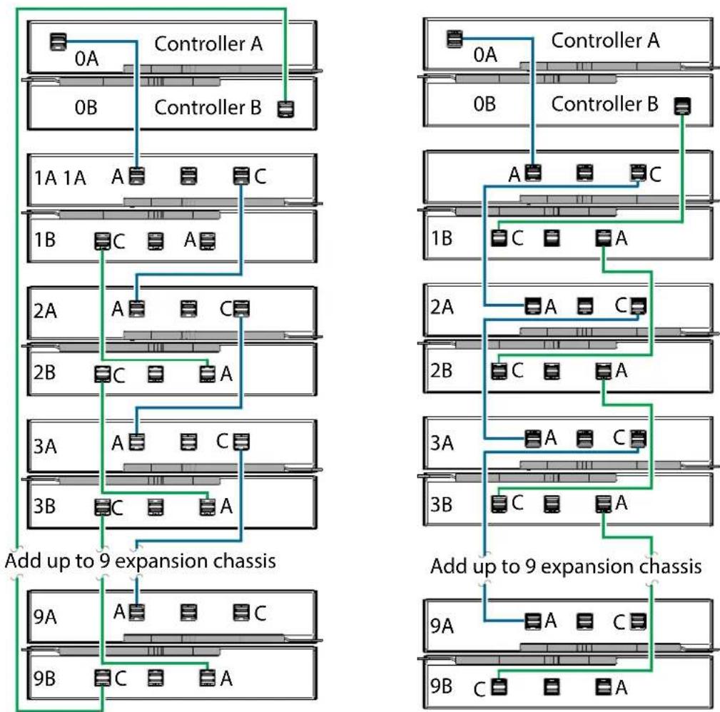
flowchart
graph TD
    subgraph Left_Circuit
        A["Controller A"] -->|0A| B["Controller B"]
        C["Controller B"] -->|0B| D["Controller A"]
        E["Controller B"] --> F["Controller A"]
        G["Controller B"] --> H["Controller A"]
        I["Controller B"] --> J["Controller A"]
        K["Controller B"] --> L["Controller A"]
        M["Controller B"] --> N["Controller A"]
        O["Controller B"] --> P["Controller A"]
        Q["Controller B"] --> R["Controller A"]
        S["Controller B"] --> T["Controller A"]
        U["Controller B"] --> V["Controller A"]
        W["Controller B"] --> X["Controller A"]
        Y["Controller B"] --> Z["Controller A"]
        AA["Controller B"] --> AB["Controller A"]
        AC["Controller B"] --> AD["Controller A"]
        AE["Controller B"] --> AF["Controller A"]
        AG["Controller B"] --> AH["Controller A"]
        AI["Controller B"] --> AJ["Controller A"]
        AK["Controller B"] --> AL["Controller A"]
        AM["Controller B"] --> AN["Controller A"]
        AO["Controller B"] --> AP["Controller A"]
        AQ["Controller B"] --> AR["Controller A"]
        AS["Controller B"] --> AT["Controller A"]
        AU["Controller B"] --> AV["Controller A"]
        AW["Controller B"] --> AX["Controller A"]
        AY["Controller B"] --> AZ["Controller A"]
        BA["Controller B"] --> BB["Controller A"]
        BC["Controller B"] --> BD["Controller A"]
        BE["Controller B"] --> BF["Controller A"]
        BG["Controller B"] --> BH["Controller A"]
        BI["Controller B"] --> BJ["Controller A"]
        BK["Controller B"] --> BL["Controller A"]
        BM["Controller B"] --> BN["Controller A"]
        BO["Controller B"] --> BP["Controller A"]
        BQ["Controller B"] --> BR["Controller A"]
        BS["Controller B"] --> BT["Controller A"]
        BU["Controller B"] --> BV["Controller A"]
        BW["Controller B"] --> BX["Controller A"]
        BY["Controller B"] --> BZ["Controller A"]
        CA["Controller B"] --> CB["Controller A"]
        CC["Controller B"] --> CD["Controller A"]
        CE["Controller B"] --> CF["Controller A"]
        DG["Controller B"] --> DH["Controller A"]
        DI["Controller B"] --> DJ["Controller A"]
        DK["Controller B"] --> DL["Controller A"]
        DM["Controller B"] --> DJ
        DB["Controller B"] --> DC["A"]
        DD["A"] --> DV["A"]
        DW["C"] --> DX["C"]
    end

    subgraph Right_Circuit
        E1["1A 1A"] --> E2["A"]
        E3["A"] --> E4["C"]
        E5["A"] --> E6["C"]
    end

    subgraph Left_Divertices
        G1["1B"] --> G2["C"]
        G3["A"] --> G4["C"]
    end

    subgraph Right_Circuit
        H1["2A"] --> H2["A"]
        H3["A"] --> H4["C"]
    end

    note right of H1 Add up to 9 expansion chassis
    note right of H2 Add up to 9 expansion chassis
    note right of H3 Add up to 9 expansion chassis
    note right of H4 Add up to 9 expansion chassis
    note right of H5 Add up to 9 expansion chassis
    note right of H6 Add up to 9 expansion chassis
    note right of H7 Add up to 9 expansion chassis
    note right of H8 Add up to 9 expansion chassis
    note right of H9 Add up to 9 expansion chassis
Reverse Cabling/Fault Tolerant Straight-through Cabling
Figure 62 (left) shows reverse cabling of a RAID chassis dual-controller 2U chassis and supported 2U drive chassis configured with dual expansion IOMs. Controller module 0A is connected to expansion module 1A, with a chain of connections cascading down (blue). Controller module 0B is connected to the lower expansion module (9B), of the last expansion chassis, with connections moving in the opposite direction (green). Reverse cabling allows any expansion chassis to fail—or be removed—while maintaining access to other chassis.
The diagram at right (above) shows the same storage components connected to use straight-through cabling. Using this method, if an expansion chassis fails, the chassis that follow the failed chassis in the chain are no longer accessible until the failed chassis is repaired or replaced.
The 2U expansion chassis shown in Figure 62 can either be of the same type or they can be a mixture of the 2U12 and 2U24 models. Given that supported expansion chassis models use 12Gb/s SAS link-rate and SAS 3.0 expanders, they can be ordered in desired sequence within the system, following the RAID chassis. The middle SAS ports (Port B) on expansion modules are not used. Refer to Expansion Chassis IOM on page 19 for additional information.
Mixing 2U and 5U84 chassis when configuring a storage system is not supported. Representative examples showing supported configurations and configuration limits are provided above for 2U12 and 2U24, and on the following pages for 5U84.
Reverse Cabling for 5U84 Systems
Figure 63 provides an illustration of connecting RAID chassis and expansion chassis in a reverse cabling (fault tolerant) configuration for 5U84 systems.
Figure 63 5U84 Reverse Cabling
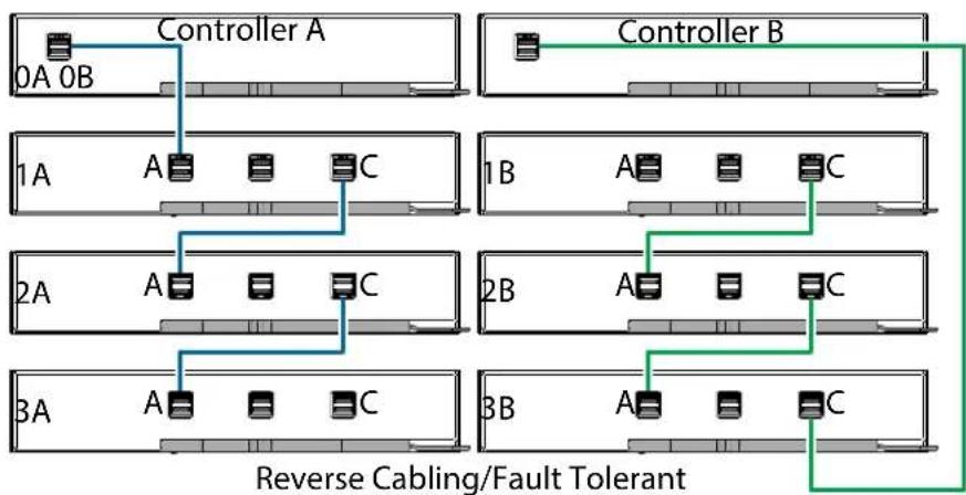
flowchart
graph TD
    subgraph_Controller_A["Controller A"]
        A0A0B["0A 0B"] --> A["A"]
        A0B --> C["C"]
    end
    subgraph_Controller_B["Controller B"]
        B["B"] --> A2["A"]
        B2["A"] --> C2["C"]
    end
    subgraph_Switch_1["Switch 1A"]
        1A["A"] --> Switch_C["C"]
    end
    subgraph_Switch_2["Switch 2A"]
        2A["A"] --> Switch_C2["C"]
    end
    subgraph_Switch_3["Switch 3A"]
        3A["A"] --> Switch_C["C"]
    end
    Switch_C --> Switch_A
    Switch_C --> Switch_B
    Switch_A --> Switch_A
    Switch_B --> Switch_B
    Switch_A --> Switch_A
    Switch_B --> Switch_B
    Switch_A --> Switch_A
    Switch_B --> Switch_B
    Switch_A --> Switch_A
    Switch_B --> Switch_B
    Switch_A --> Reverse_Cabling["Fault Tolerant"]
    Switch_B --> Reverse_Cabling
    Switch_A --> Reverse_Cabling
    Switch_B --> Reverse_Cabling
Straight-Through Cabling for 5U84 Systems
Figure 64 provides an illustration of connecting RAID chassis and expansion chassis in a straight-through cabling configuration for 5U84 systems.
Figure 64 5U84 Straight-Through Cabling
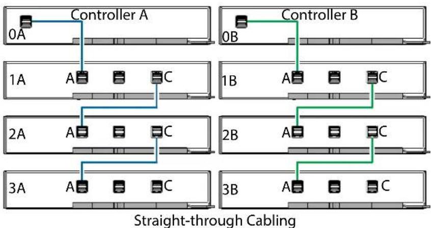
flowchart
graph TD
    subgraph_Controller_A["Controller A"]
        0A["0A"] --> Controller_A
        Controller_A --> Controller_B["0B"]
    end
    subgraph_Controller_B["Controller B"]
        1A["1A"] --> Controller_A
        Controller_A --> Controller_B
        Controller_B --> Controller_B
    end
    subgraph_Switch1["Switch 1A"]
        2A["2A"] --> Controller_A
        Controller_A --> Controller_B
        Controller_B --> Controller_B
    end
    subgraph_Switch2["Switch 2A"]
        3A["3A"] --> Controller_A
        Controller_A --> Controller_B
        Controller_B --> Controller_B
    end
    subgraph_Switch3["Switch 3A"]
        3B["3B"] --> Controller_A
        Controller_A --> Controller_B
        Controller_B --> Controller_B
    end
NOTE: Figure 63 and Figure 64 show maximum configuration cabling for the 5U84 RAID chassis with the 5U84 expansion chassis (total of 4 chassis cabled together).
CAUTION: Refer to Connecting RAID Chassis and Expansion Chassis on page 66 for comparative characteristics for using reverse cabling (fault tolerant) or straight-through cabling configurations.
Reverse Cabling for 2U to 5U84 Systems
Figure 65 provides an illustration of connecting a 2U RAID chassis and three 5U84 expansion chassis in a reverse cabling configuration.
Figure 65 2U RAID Chassis to 5U84 Expansion Chassis Reverse Cabling
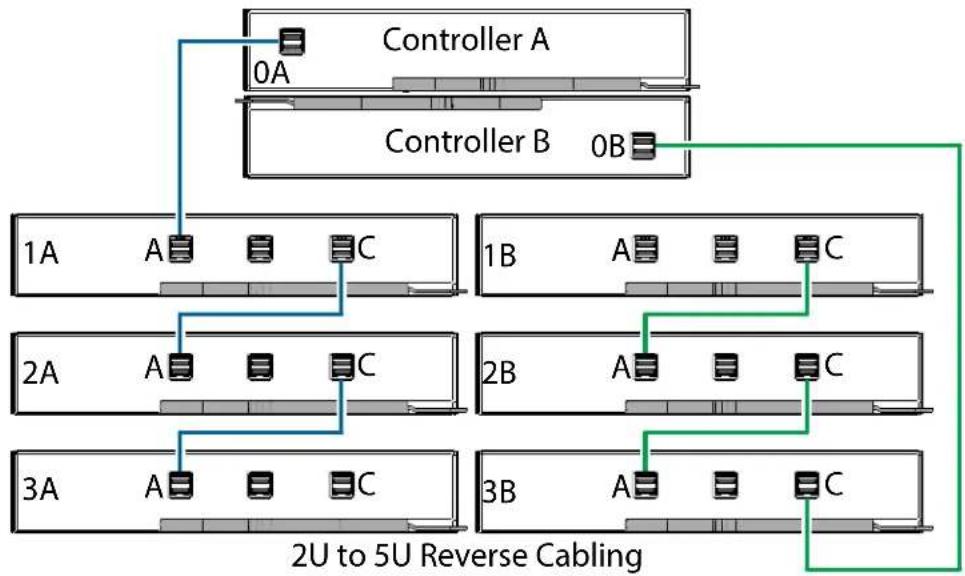
flowchart
graph TD
    Controller_A["Controller A"] -->|0A| Server1["Server Rack 1A"]
    Controller_B["Controller B"] -->|0B| Server2["Server Rack 2B"]
    Server1 -->|A| C1["C"]
    Server2 -->|A| C2["C"]
    Server1 -->|C| C3["C"]
    Server2 -->|C| C4["C"]
    Server3["Server Rack 3A"] -->|A| C5["C"]
    Server3 -->|A| C6["C"]
    Server3 -->|A| C7["C"]
    Server3 -->|C| C8["C"]
    Server4["Server Rack 3B"] -->|A| C9["C"]
    Server4 -->|A| C10["C"]
    Server4 -->|C| C11["C"]
    Server4 -->|C| C12["C"]
    Server4 -->|C| C13["C"]
    Server4 -->|C| C14["C"]
    Server4 -->|C| C15["C"]
    Server4 -->|C| C16["C"]
    Server4 -->|C| C17["C"]
    Server4 -->|C| C18["C"]
    Server4 -->|C| C19["C"]
    Server4 -->|C| C20["C"]
    Server4 -->|C| C21["C"]
    Server4 -->|C| C22["C"]
    Server4 -->|C| C23["C"]
    Server4 -->|C| C24["C"]
    Server4 -->|C| C25["C"]
    Server4 -->|C| C26["C"]
    Server4 -->|C| C27["C"]
    Server4 -->|C| C28["C"]
    Server4 -->|C| C29["C"]
    Server4 -->|C| C30["C"]
    Server4 -->|C| C31["C"]
    Server4 -->|C| C32["C"]
    Server4 -->|C| C33["C"]
    Server4 -->|C| C34["C"]
    Server4 -->|C| C35["C"]
    Server4 -->|C| C36["C"]
    Server4 -->|C| C37["C"]
    Server4 -->|C| C38["C"]
    Server4 -->|C| C39["C"]
    Server4 -->|C| C40["C"]
Straight-Through Cabling for 2U to 5U84 Systems
Figure 66 provides an illustration of connecting a 2U RAID chassis and three 5U84 expansion chassis in a straight-through cabling configuration.
Figure 66 2U RAID Chassis to 5U84 Expansion Chassis Straight-Through Cabling
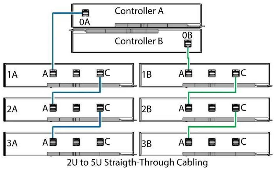
flowchart
graph TD
    subgraph_Controller_A["Controller A"]
        A0A["0A"] --> A1A["A"]
        B0B["0B"] --> B1B["A"]
    end
    subgraph_Controller_B["Controller B"]
        B1B --> B2B["A"]
        C1C["C"]
    end
    A0A --> A1A
    B0B --> B1B
    A1A --> A2A["A"]
    B1B --> B2B["A"]
    C1C --> C2C["C"]
    A2A --> A3A["A"]
    B2B --> B3B["A"]
    C2C --> C3C["C"]
    A3A --> A4A["A"]
    B3B --> B4A["A"]
    style Controller_A fill:#f9f,stroke:#333
    style Controller_B fill:#f9f,stroke:#333
    note bottom of A2A: 2U to 5U Straight-Through Cable
    note bottom of B3B: 2U to 5U Straight-Through Cable
NOTE: Figure 65 and Figure 66 show maximum configuration cabling for a 2U RAID chassis with the 5U84 expansion chassis (total of 4 chassis cabled together).
Power Cord Connection
Connect a power cord from each PSU on the chassis rear panel to the PDU (power distribution unit) as shown in the illustrations below.
Figure 67 provides an illustration of connecting 2U RAID chassis PSUs to an AC PDU.
Figure 67 Connecting 2U RAID chassis PSUs to AC PDU
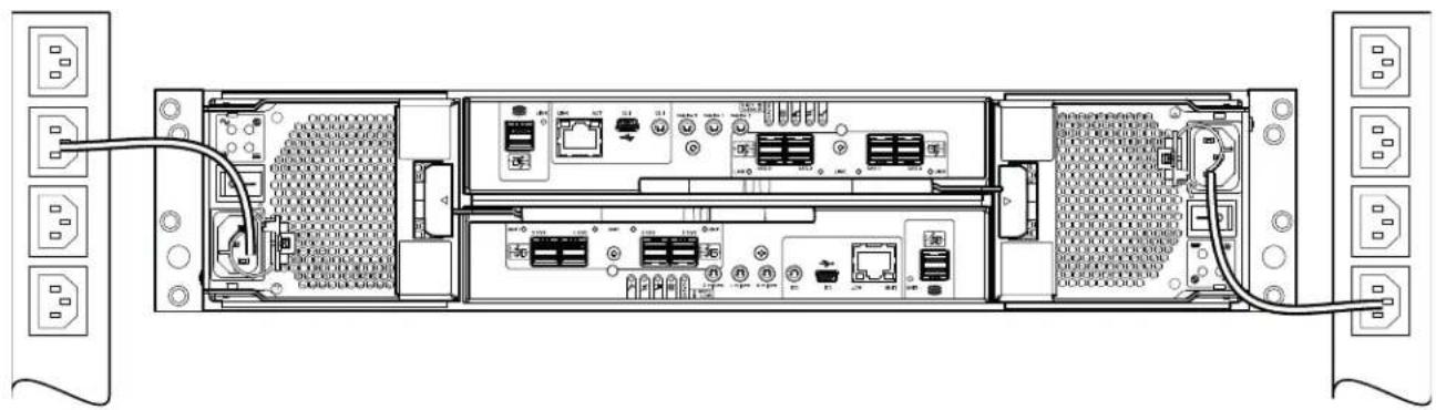
natural_image
Back view diagram of a network equipment chassis showing internal components and external connectors (no text or labels)Figure 68 provides an illustration of connecting 5U RAID chassis PSUs to an AC PDU.
Figure 68 Connecting 5U RAID chassis PSUs to AC PDU
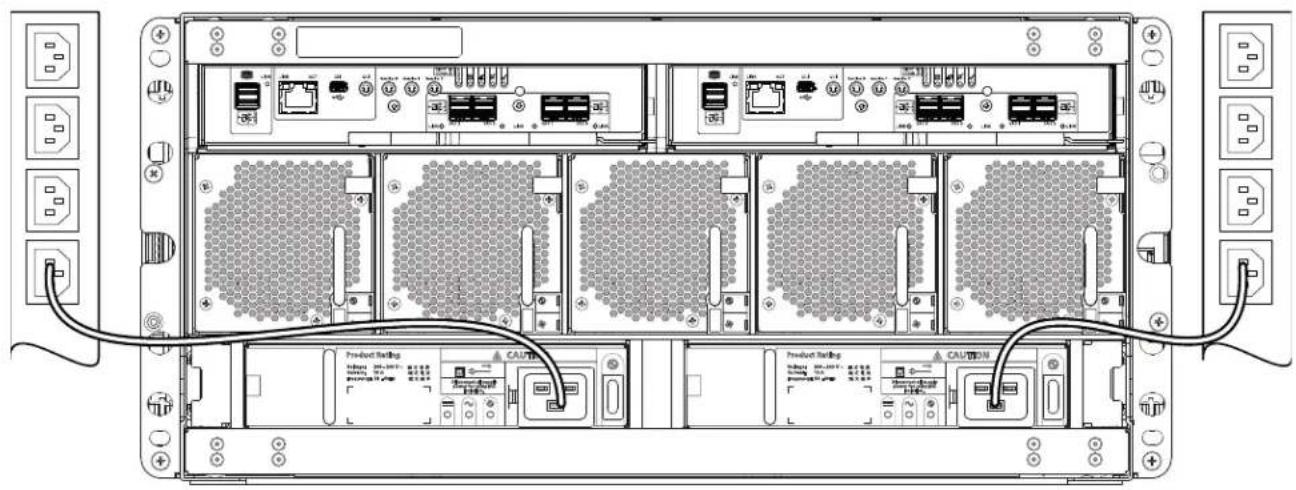
IMPORTANT: When more than one PSU is fitted, all power cords must be connected to at least two separate and independent power supplies to ensure redundancy. When the storage system is ready for operation, ensure that each PSU power switch is set to the On position.
CAUTION: Power connection concerns:
• Always remove the power connections before you remove the PSU from the chassis.
- When bifurcated power cords (Y leads) are used, these cords must only be connected to a supply range of 200–240V AC.
Testing Chassis Connections
See Powering On/Powering Off on page 105. Once the power-on sequence succeeds, the storage system is ready to be connected as described in Host Connection on page 76.
Grounding Checks
The product must only be connected to a power source that has a safety electrical earth connection.
CAUTION: If more than one chassis goes into a rack, the importance of the earth connection to the rack increases because the rack will have a larger Earth Leakage Current (Touch Current).
Examine the earth connection to the rack before power on. An electrical engineer who is qualified to the appropriate local and national standards must do the examination.
Host System Requirements
NOTE: Refer to the QXS 12G Quantum Interoperability and Certification Matrix for Quantum model numbers, firmware release, firmware required for host systems, RAID hardware certifications, and HBA attach.
When attaching the QXS 12G system to applicable Quantum Appliances, refer to the Quantum Appliance support/requirements.
Hosts connected to QXS-312 12G, QXS-324 12G, QXS-412 12G, QXS-424 12G, and QXS-484 12G systems must meet the following requirements:
- Depending on your system configuration, host operating systems may require that multipathing is supported.
- If fault tolerance is required, then multipathing software may be required.
- Host-based multipath software should be used in any configuration where two logical paths between the host and any storage volume may exist at the same time.
- This would include most configurations where there are multiple connections to the host or multiple connections between a switch and the storage.
- Use native Microsoft MPIO DSM support with Windows Server 2008, Windows Server 2012, and Windows Server 2016.
Use either the Server Manager or the mpclaim CLI tool to perform the installation.
See the following web sites for information about using native Microsoft MPIO DSM:
- https://support.microsoft.com
- https://technet.microsoft.com (search the site for "multipath I/O overview")
Cabling Considerations
Common cabling configurations address hosts, RAID chassis, expansion chassis, and switches. Host interface ports on the QXS-312 12G, QXS-324 12G, QXS-412 12G, QXS-424 12G, and QXS-484 12G RAID chassis can connect to respective hosts via direct-attach or switch-attach. Cabling systems to
enable use of the optional replication feature—to replicate volumes—is yet another important cabling consideration. See Connecting Management Host to Network on page 83. The FC and iSCSI product models can be licensed to support replication.
Use only QXS-312 12G, QXS-324 12G, QXS-412 12G, QXS-424 12G, and QXS-484 12G system or OEM-qualified cables to connect host to RAID chassis:
- Qualified Fibre Channel SFP and cable options
- Qualified 10GbE iSCSI SFP and cable options
• Qualified 1Gb RJ-45 SFP and cable options
A host identifies an external port to which the storage system is attached. The external port may be a port in an I/O adapter (such as an FC HBA) in a server. Cable connections vary depending on configuration. This section describes host interface protocols supported by QXS-312 12G, QXS-324 12G, QXS-412 12G, QXS-424 12G, and QXS-484 12G RAID chassis, while showing a few common cabling configurations.
NOTE: QXS-312 12G, QXS-324 12G, QXS-412 12G, QXS-424 12G, and QXS-484 12G controllers use Unified LUN Presentation (ULP), which enables a host to access mapped volumes through any controller host port.
ULP can show all LUNs through all host ports on both controllers, and the interconnect information is managed by the controller firmware. ULP appears to the host as an active-active storage system, allowing the host to select any available path to access the LUN, regardless of disk group ownership.
TIP: See the topic about configuring system settings in the QXS 12G Disk Management Utility User Guide to initially configure the system, or change system configuration settings (such as Configuring host ports).
CNC Technology
The QXS-312 12G, QXS-324 12G, QXS-412 12G, QXS-424 12G, and QXS-484 12G FC/iSCSI models use Converged Network Controller (CNC) technology, allowing you to select the desired host interface protocol(s) from the available FC or iSCSI host interface protocols supported by the system. The small form-factor pluggable (SFP transceiver or SFP) connectors used in CNC ports are further described in the subsections below.
Refer to the following for additional CNC information:
- QXS-412 12G, QXS-424 12G, and QXS-484 12G RAID Chassis Rear View (4-Host Port Controllers) on page 18
• QXS-312 12G and QXS-324 12G RAID Chassis Rear View (2-Host Port Controllers) on page 16
• 5U84 RAID Chassis (Rear View/Two CNC Controllers) on page 24
NOTE: Controller modules are shipped with SFPs installed (FC or iSCSI per customer order).
CAUTION: Use the set host-port-mode CLI command to set the host interface protocol for CNC ports using qualified SFP options (if required).
- QXS-312 12G, QXS-324 12G, QXS-412 12G, QXS-424 12G, and QXS-484 12G models ship with CNC ports configured for FC or iSCSI per customer order.
- Using FC or iSCSI SFPs in combination is not supported currently.
- If the customer changes SFPs, you must use the CLI (not the disk management utility, GUI) to specify which ports will use FC or iSCSI.
- It is best to do this before inserting the SFPs into the CNC ports (see Change CNC Port Mode on page 98 for instructions).
Fibre Channel (FC) Protocol
NOTE: A FC protocol connectivity kit must be purchased from Quantum; it contains qualified SFPs and cables to support the FC protocol.
The QXS-312 12G, QXS-324 12G, QXS-412 12G, QXS-424 12G, and QXS-484 12G RAID chassis support two controller modules using the Fibre Channel interface protocol for host connection.
• The QXS-312 12G and QXS-324 12G FC controller module provides two host ports.
- The QXS-412 12G, QXS-424 12G, and QXS-484 12G FC controller module provides four host ports.
• CNC ports are designed for use with an FC SFP supporting data rates up to 16Gb/s.
The controllers support Fibre Channel Arbitrated Loop (public or private) or point-to-point topologies. Loop protocol can be used in a physical loop or for direct connection between two devices. Point-to-point protocol is used to connect to a fabric switch. Point-to-point protocol can also be used for direct connection, and it is the only option supporting direct connection at 16Gb/s.
See the set host-parameters command within the QXS 12G CLI Reference Guide for command syntax and details about parameter settings relative to supported link speeds. Fibre Channel ports are used for attachment to FC hosts directly, or through a switch used for the FC traffic. The host computer must support FC and optionally, multipath I/O.
The Fibre Channel ports are used in either of two capacities:
- To connect two storage systems through a switch for use of replication.
- For attachment to FC hosts directly, or through a switch used for the FC traffic.
The first usage option requires valid licensing for the replication feature, whereas the second option requires that the host computer supports Ethernet, FC, and optionally, multipath I/O.
TIP: Use the disk management utility (GUI) to set FC port speed. Within the QXS12G Disk Management Utility User Guide, see the topic about configuring host ports.
Use the set host-parameters CLI command to set FC port options, and use the show ports CLI command to view information about host ports.
NOTE: A 10 GbE protocol connectivity kit must be purchased from Quantum; it contains qualified SFPs and cables to support the 10 GbE protocol.
The QXS-312 12G, QXS-324 12G, QXS-412 12G, QXS-424 12G, and QXS-484 12G RAID chassis 10GbE iSCSI controllers support two controller modules using the Internet SCSI interface protocol for host connection.
• The QXS-312 12G and QXS-324 12G 10GbE iSCSI controller module provides two host ports.
- The QXS-412 12G, QXS-424 12G, and QXS-484 12G 10GbE iSCSI controller module provides four host ports.
- CNC ports are designed for use with a 10GbE iSCSI SFP supporting data rates up to 10Gb/s, using either one-way or mutual CHAP (Challenge-Handshake Authentication Protocol).
The 10GbE iSCSI ports are used in either of two capacities:
- To connect two storage systems through a switch for use of replication.
- For attachment to 10GbE iSCSI hosts directly, or through a switch used for the 10GbE iSCSI traffic.
The first usage option requires valid licensing for the replication feature, whereas the second option requires that the host computer supports Ethernet, iSCSI, and optionally, multipath I/O.
TIP: See the topic about configuring CHAP in the QXS 12G Disk Management Utility User Guide.
TIP: Use the disk management utility (GUI) to set iSCSI port options. Within the QXS 12G Disk Management Utility User Guide, see the topic about configuring host ports.
Use the set host-parameters CLI command to set iSCSI port options, and use the show ports CLI command to view information about host ports.
1Gb iSCSI Protocol
NOTE: A 1 GbE protocol connectivity kit must be purchased from Quantum; it contains qualified SFPs and cables to support the 1 GbE protocol.
The QXS-312 12G, QXS-324 12G, QXS-412 12G, QXS-424 12G, and QXS-484 12G RAID chassis 1Gb iSCSI controllers support two controller modules using the Internet SCSI interface protocol for host port connection.
• The QXS-312 12G and QXS-324 12G 1Gb iSCSI controller module provides two host ports.
- The QXS-412 12G, QXS-424 12G, and QXS-484 12G 1Gb iSCSI controller module provides four host ports.
- The CNC ports are designed for use with an RJ-45 SFP supporting data rates up to 1Gb/s, using either one-way or mutual CHAP.
TIP: See the topic about configuring CHAP in the .
TIP: Use the disk management utility (GUI) to set iSCSI port options. Within the, see the topic about configuring host ports.
Use the set host-parameters CLI command to set iSCSI port options, and use the show ports CLI command to view information about host ports.
The 1Gb iSCSI ports are used in either of two capacities:
- To connect two storage systems through a switch for use of replication.
- For attachment to 1Gb iSCSI hosts directly, or through a switch used for the 1Gb iSCSI traffic.
The first usage option requires valid licensing for the replication feature, whereas the second option requires that the host computer supports Ethernet, iSCSI, and optionally, multipath I/O.
Host Connection
The QXS-312 12G and QXS-324 12G RAID chassis support up to four direct-connect server connections, two per controller module.
- Use only qualified cables purchased from Quantum for all host connections.
- Connect appropriate cables from the server's HBAs to the controller module's host ports as described below, and shown in the following illustrations.
The QXS-412 12G, QXS-424 12G, and QXS-484 12G RAID chassis support up to eight direct-connect server connections, four per controller module.
- Use only qualified cables purchased from Quantum for all host connections.
- Connect appropriate cables from the server's HBAs to the controller module's host ports as described below, and shown in the following illustrations.
Fibre Channel Host Connection
To connect controller modules supporting (4/8/16Gb) FC host interface ports to a server HBA or switch, using the controller's CNC ports, select a qualified FC SFP option.
Qualified options support cable lengths of 1 m (3.28'), 2 m (6.56'), 5 m (16.40'), 15 m (49.21'), 30 m (98.43'), and 50 m (164.04') for OM4 multimode optical cables and OM3 multimode FC cables, respectively. A 0.5 m (1.64') cable length is also supported for OM3. In addition to providing host connection, these cables are used for connecting two storage systems via a switch, to facilitate use of the optional replication feature.
10GbE iSCSI Host Connection
To connect controller modules supporting 10GbE iSCSI host interface ports to a server HBA or switch, using the controller's CNC ports, select a qualified 10GbE SFP option.
Qualified options support cable lengths of 0.5 m (1.64'), 1 m (3.28'), 3 m (9.84'), 5 m (16.40'), and 7 m (22.97') for copper cables; and cable lengths of 0.65 m (2.13'), 1 m (3.28'), 1.2 m (3.94'), 3 m (9.84'), 5 m (16.40'), and 7 m (22.97') for direct attach copper (DAC) cables. In addition to providing host connection, these cables are used for connecting two storage systems via a switch, to facilitate use of the optional replication feature.
1Gb iSCSI Host Connection
To connect controller modules supporting 1Gb iSCSI host interface ports to a server HBA or switch, using the controller's CNC ports, select a qualified 1Gb RJ-45 copper SFP option supporting (CAT5-E minimum) Ethernet cables of the same lengths specified for 10GbE iSCSI above. In addition to providing host connection, these cables are used for connecting two storage systems via a switch, to facilitate use of the optional replication feature.
Connecting Direct Attach Configurations
A dual-controller configuration improves application availability because in the event of a controller failure, the affected controller fails over to the healthy partner controller with little interruption to data flow. A failed controller can be replaced without the need to shut down the storage system. The QXS-312 12G, QXS-324 12G, QXS-412 12G, QXS-424 12G, and QXS-484 12G RAID chassis are configured with dual controller modules.
NOTE: In the examples that follow, a single diagram represents CNC host connections for QXS-312 12G, QXS-324 12G, QXS-412 12G, QXS-424 12G, and QXS-484 12G RAID chassis respectively. The location and sizes of the host ports are very similar. Blue cables show controller A paths and green cables show controller B paths for host connection.
2U12/2U24 (4-Host Ports) One Server/One HBA/Dual Path
Figure 69 provides an illustration of connecting a 2U12/2U24 to one server/one HBA with dual path.
Figure 69 2U12/2U24 One Server/One HBA/Dual Path
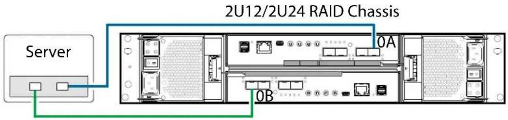
2U12/2U24 (2-Host Ports) One Server/One HBA/Dual Path
Figure 70 provides an illustration of connecting a 2U12/2U24 to one server/one HBA with dual path.
Figure 70 2U12/2U24 One Server/One HBA/Dual Path
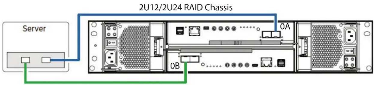
5U84 One Server/One HBA/Dual Path
Figure 71 provides an illustration of connecting a 5U84 to one server/one HBA with dual path.
Figure 71 5U84 One Server/One HBA/Dual Path
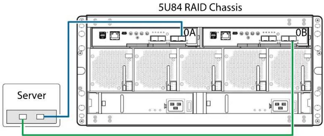
2U12/2U24 (4-Host Ports) Two Servers/One HBA Per Server/Dual Path
Figure 72 provides an illustration of connecting a 2U12/2U24 to two servers/one HBA per server, with dual path.
Figure 72 2U12/2U24 Two Servers/One HBA Per Server/Dual Path

flowchart
graph LR
    Server_1["Server 1"] --> PortA["0A"]
    PortA --> PortB["0B"]
    PortB --> PortC["0B"]
    PortC --> Server_2["Server 2"]
    Port A --> Port C
    Port B --> Port C
    Port C --> Port A
    Port A --> Port C
    Port B --> Port C
    Port C --> Port A
    Port A --> Port C
    Port B --> Port C
    Port C --> Port A
    Port A --> Port C
    Port B --> Port C
    Port C --> Port A
2U12/2U24 (2-Host Ports) Two Servers/One HBA Per Server/Dual Path
Figure 73 provides an illustration of connecting a 2U12/2U24 to two servers/one HBA per server, with dual path.
Figure 73 2U12/2U24 Two Servers/One HBA Per Server/Dual Path

5U84 Two Servers/One HBA Per Server/Dual Path
Figure 74 provides an illustration of connecting a 5U84 to two servers/one HBA per server, with dual path.
Figure 74 5U84 Two Servers/One HBA Per Server/Dual Path
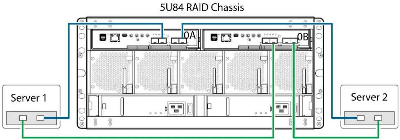
2U12/2U24 Four Servers/One HBA Per Server/Dual Path
Figure 75 provides an illustration of connecting a 2U12/2U24 to four servers/one HBA per server, with dual path.
Figure 75 2U12/2U24 Four Servers/One HBA Per Server/Dual Path
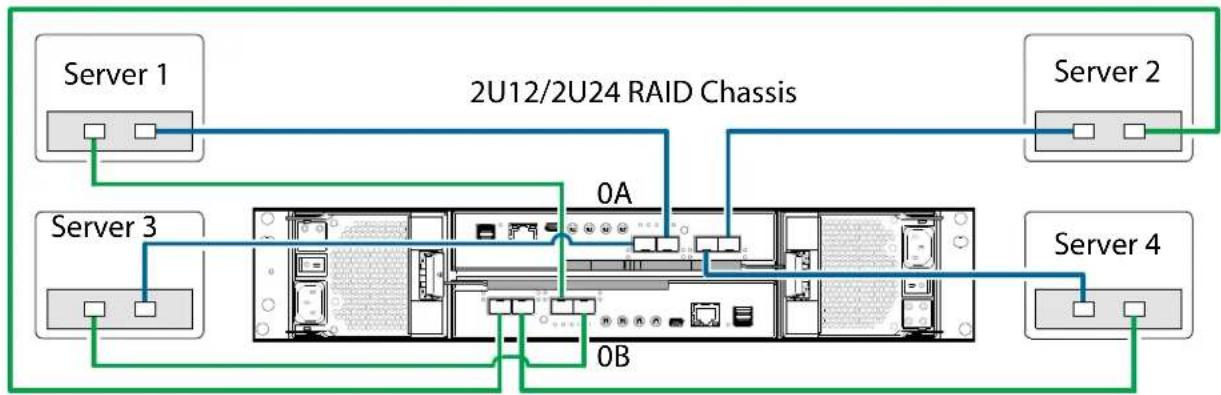
flowchart
graph TD
    Server1["Server 1"] --> A["0A"]
    Server3["Server 3"] --> B["0B"]
    Server2["Server 2"] --> C["0A"]
    Server4["Server 4"] --> D["0B"]
    A --> E["2U12/2U24 RAID Chassis"]
    B --> E
    C --> E
    D --> E
5U84 Four Servers/One HBA Per Server/Dual Path
Figure 76 provides an illustration of connecting a 5U84 to four servers/one HBA per server, with dual path.
Figure 76 5U84 Four Servers/One HBA Per Server/Dual Path
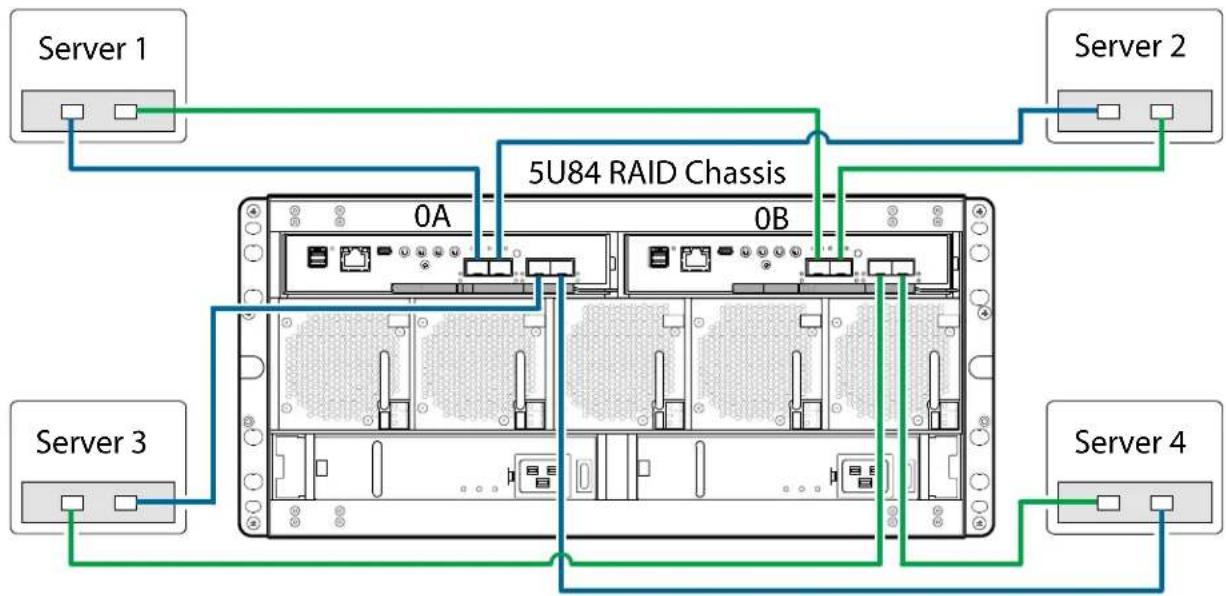
flowchart
graph TD
    Server1["Server 1"] --> A["0A"]
    Server2["Server 2"] --> B["0B"]
    Server3["Server 3"] --> C["0A"]
    Server4["Server 4"] --> D["0B"]
    A --> E["5U84 RAID Chassis"]
    B --> E
    C --> E
    D --> E
Switch Attach
A switch attach solution—or SAN—places a switch between the servers and the RAID chassis within the storage system. Using switches, a SAN shares a storage system among multiple servers, reducing the number of storage systems required for a particular environment. Using switches increases the number of servers that can be connected to the storage system.
2U12/2U24 (4-Host Ports) Two Servers/Two Switches
Figure 77 provides an illustration of connecting a 2U12/2U24 to two servers and two switches.
Figure 77 2U12/2U24 Two Servers/Two Switches
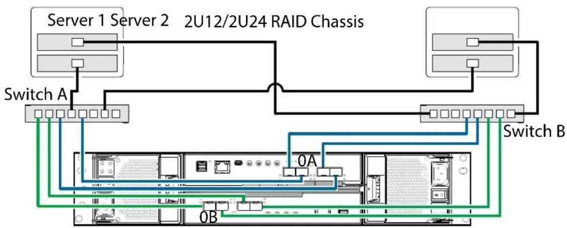
flowchart
graph TD
    subgraph Server 1
        Server1["Server 1"] --> SwitchA["Switch A"]
    end
    subgraph Server 2
        Server2["Server 2"] --> SwitchA
    end
    subgraph Switch A
        SwitchA --> SwitchB["Switch B"]
    end
    subgraph Switch B
        SwitchB --> SwitchA
    end
    SwitchA --> SwitchB
    SwitchB --> SwitchA
    SwitchA --> SwitchB
    SwitchB --> SwitchA
    SwitchA --> SwitchB
    SwitchB --> SwitchA
    SwitchA --> SwitchB
    SwitchB --> SwitchA
    SwitchA --> SwitchB
    SwitchB --> SwitchA
    SwitchA --> SwitchB
    SwitchB --> SwitchA
    SwitchA --> SwitchB
    SwitchB --> SwitchA
2U12/2U24 (2-Host Ports) Two Servers/Two Switches
Figure 78 provides an illustration of connecting a 2U12/2U24 to two servers and two switches.
Figure 78 2U12/2U24 Two Servers/Two Switches
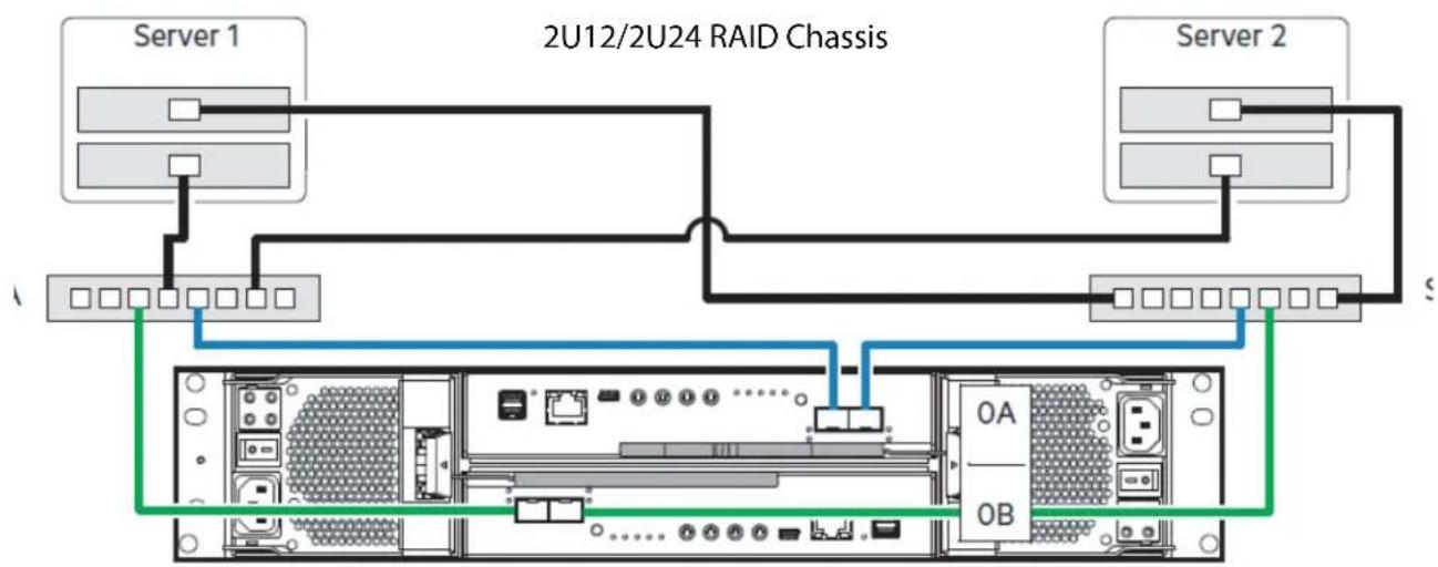
flowchart
graph TD
    Server1["Server 1"] -->|A| Rack1["RAM"]
    Server1 -->|B| Rack2["RAM"]
    Server2["Server 2"] -->|S| Rack3["RAM"]
    Rack1 -->|A| Rack4["RAM"]
    Rack1 -->|B| Rack5["RAM"]
    Rack2 -->|A| Rack6["RAM"]
    Rack2 -->|B| Rack7["RAM"]
    Rack4 -->|A| Rack8["RAM"]
    Rack4 -->|B| Rack9["RAM"]
    Rack5 -->|A| Rack10["RAM"]
    Rack5 -->|B| Rack11["RAM"]
    Rack6 -->|A| Rack12["RAM"]
    Rack6 -->|B| Rack13["RAM"]
    Rack7 -->|A| Rack14["RAM"]
    Rack7 -->|B| Rack15["RAM"]
    Rack8 -->|A| Rack16["RAM"]
    Rack8 -->|B| Rack17["RAM"]
5U84 Two Servers/Two Switches
Figure 79 provides an illustration of connecting a 5U84 to two servers and two switches.
Figure 79 5U84 Two Servers/Two Switches
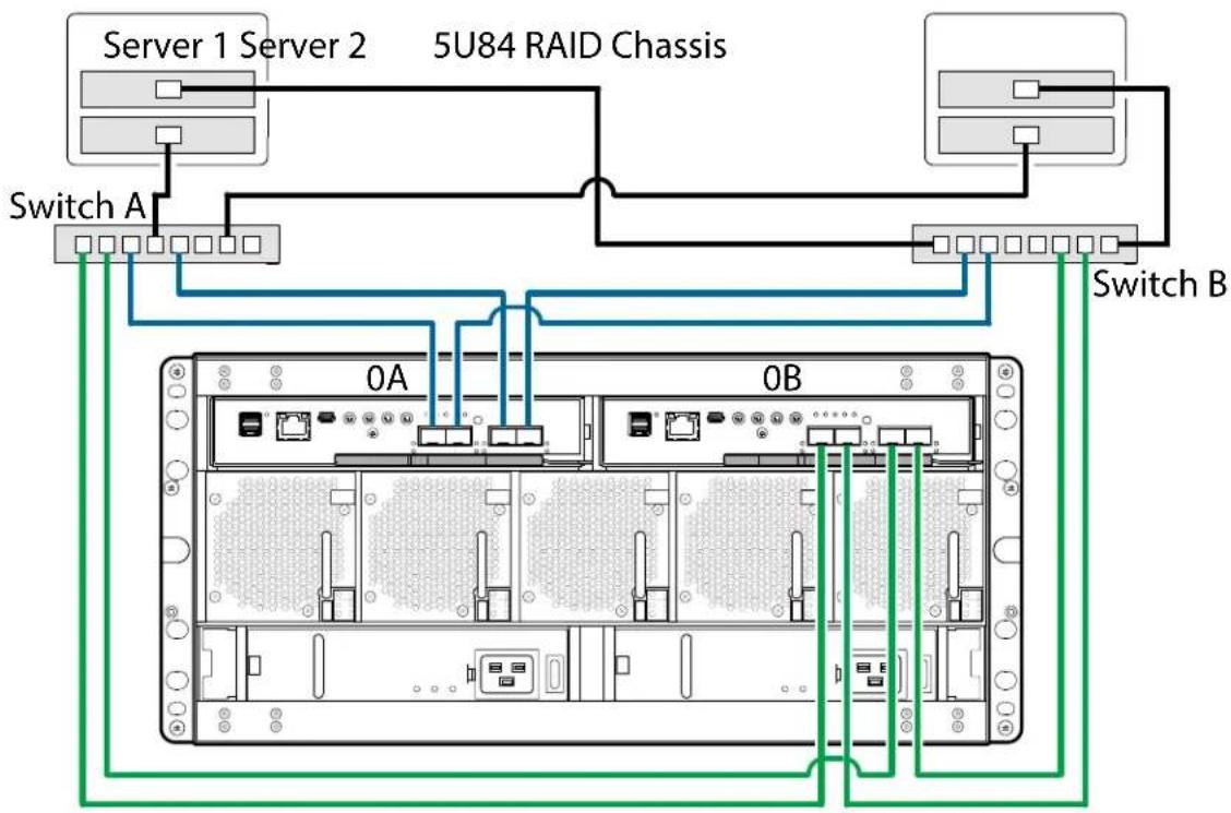
2U12/2U24 Four Servers/Multiple Switches/SAN Fabric
Figure 80 provides an illustration of connecting a 2U12/2U24 to four servers, multiple switches, and a SAN fabric.
Figure 80 2U12/2U24 Four Servers/Multiple Switches/SAN Fabric
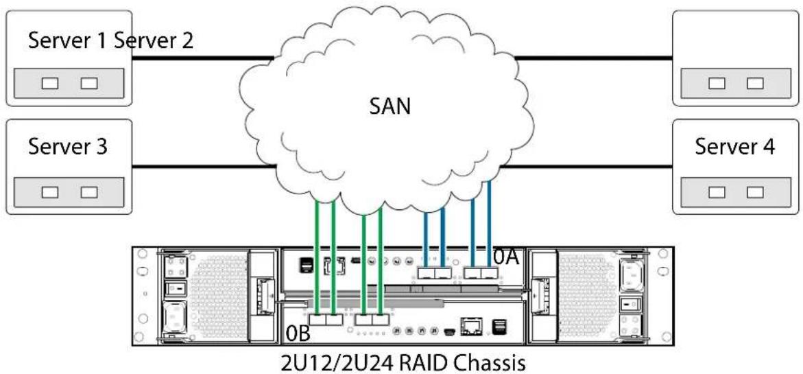
flowchart
graph TD
    A["Server 1 Server 2"] --> B["SAN"]
    C["Server 3"] --> B
    D["Server 4"] --> B
    B --> E["0A"]
    B --> F["0B"]
    B --> G["2U12/2U24 RAID Chassis"]
5U84 Four Servers/Multiple Switches/SAN Fabric
Figure 81 provides an illustration of connecting a 5U84 to four servers, multiple switches, and a SAN fabric.
Figure 81 5U84 Four Servers/Multiple Switches/SAN Fabric
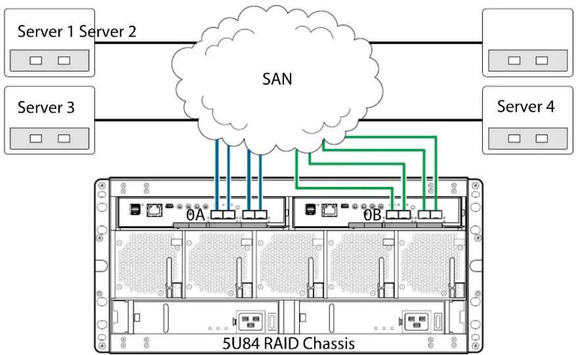
flowchart
graph TD
    A["Server 1 Server 2"] --> B["SAN"]
    C["Server 3"] --> B
    D["Server 4"] --> B
    B --> E["0A"]
    B --> F["0B"]
    E --> G["5U84 RAID Chassis"]
    F --> G
    G --> H["Server 2"]
    G --> I["Server 3"]
    G --> J["Server 4"]
Connecting Management Host to Network
The management host directly manages storage systems out-of-band over an Ethernet network.
1 Connect an RJ-45 Ethernet cable to the network port on each controller(Figure 82 and Figure 83).
2 Connect the other end of each Ethernet cable to a network that your management host can access (preferably on the same subnet).
3 Do not interconnect iSCSI and management Ethernet on the same network.
Figure 82 2U RAID Chassis to Management Network
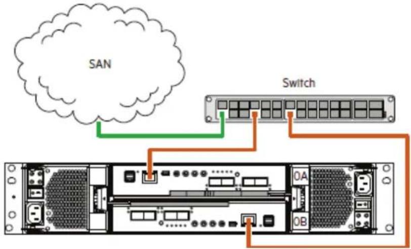
Figure 83 5U84 RAID Chassis to Management Network
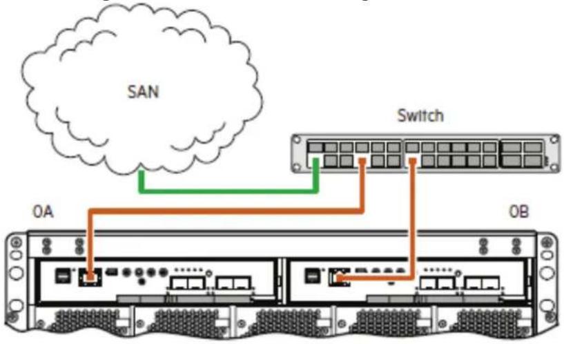
flowchart
graph TD
    SAN["SAN"] --> Switch["Switch"]
    Switch --> 0A["0A Port"]
    Switch --> 0B["0B Port"]
    0A --> 0B
    0B --> 0A
    style SAN fill:#f9f,stroke:#333
    style Switch fill:#bbf,stroke:#333
NOTE: Connections to this device must be made with shielded cables—grounded at both ends with metallic RFI/EMI connector hoods—in order to maintain compliance with FCC Rules and Regulations.
- If you connect the iSCSI and management ports to the same physical switches, separate VLANs are recommended.
- See also the topic about configuring controller network ports in the Storage Management Guide.
Updating Firmware
This section provides the following information:
- Important Firmware Notes
- Verifying Firmware
Important Firmware Notes
CAUTION: Reverting to a previous firmware version is not recommended. Notify Quantum support for additional information.
Current firmware release is available from Quantum.
Always update controller firmware to the latest when:
- Installing a new system
- Adding expansion chassis
- Replacing a RAID chassis or an expansion chassis
- Replacing a controller module(s)
- Controller replacement should auto-level with PFU enabled.
• Refer to RAID Controller on page 183 for CRU and PFU information. - Replacing an expansion I/O module(s)
NOTE: Updating controller firmware with expansion I/O modules active ensures that the controller firmware and expansion I/O module(s) firmware are at a compatible level.
Verify drive firmware and update using the disk management utility.
Verifying Firmware
NOTE: Refer to the QXS 12G G265xxxx Release Notes for the latest supported firmware for the applicable system you are installing.
After installing the hardware and powering on the storage system components for the first time, verify that the controller modules, expansion IOMs, and disk drives are using the current firmware release.
• Using the disk management utility (GUI), in the System topic, select Action > Update Firmware.
- The Update Firmware panel opens.
- The Update Controller Module tab shows versions of firmware components currently installed in each controller.
NOTE: The disk management utility (GUI) provides an option for enabling or disabling Partner Firmware Update for the partner controller.
- To enable or disable the setting, use the set advanced-settings CLI command, and set the partner-firmware-upgrade parameter.
• See the QXS 12G CLI Reference Guide for more information about command parameter syntax.
Optionally, you can update firmware using FTP or SFTP as described in the .
See the topic about updating firmware in the QXS 12G Disk Management Utility User Guide before performing a firmware update. Partner Firmware Update (PFU) is enabled by default on QXS-412 12G, QXS-424 12G, and QXS-484 12G systems.
Obtaining IP Values and System Settings
You can manually set static IP values (default method) for each controller, or you can specify that IP values should be set automatically for both controllers through communication with a Dynamic Host Configuration Protocol (DHCP) server.
See the topic about configuring network ports in the QXS 12G Disk Management Utility User Guide.
This section provides the following information:
- Updating System Settings using the Disk Management Utility (DMU) GUI
- Setting Network Port IP Addresses Using DHCP
- Setting Network Port IP Addresses Using CLI Port and Cable
Updating System Settings using the Disk Management Utility (DMU) GUI
Network ports on controller module A and controller module B are configured with the following default values:
• Network port IP address: 10.0.0.2 (controller A), 10.0.0.3 (controller B)
• IP subnet mask: 255.255.255.0
• Gateway IP address: 10.0.0.1
NOTE: Refer to the QXS 12G Disk Management Utility User Guide for additional information.
Complete only the steps that are needed. You may only need to set up the IP addresses for your system administrator to access the system and to configure it. You may also need to converse with your system administrator to complete the applicable steps needed for this system install.
Complete the applicable steps to update the system settings:
1 Log in to the disk management utility, GUI.
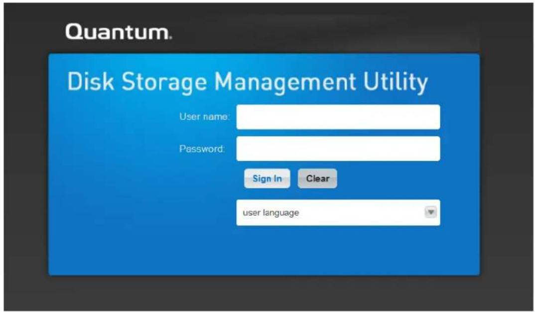
2 Click on System > Action > System Settings.
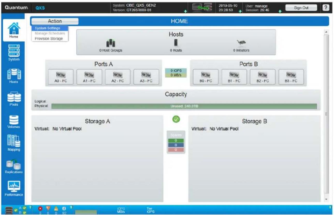
NOTE: When you change any setting in the System Settings panel, the Apply and Close and the Apply buttons will become active. To save your changes and continue changing other settings click the Apply button. To save your changes and exit click the Apply and Close button.
The following screen appear.
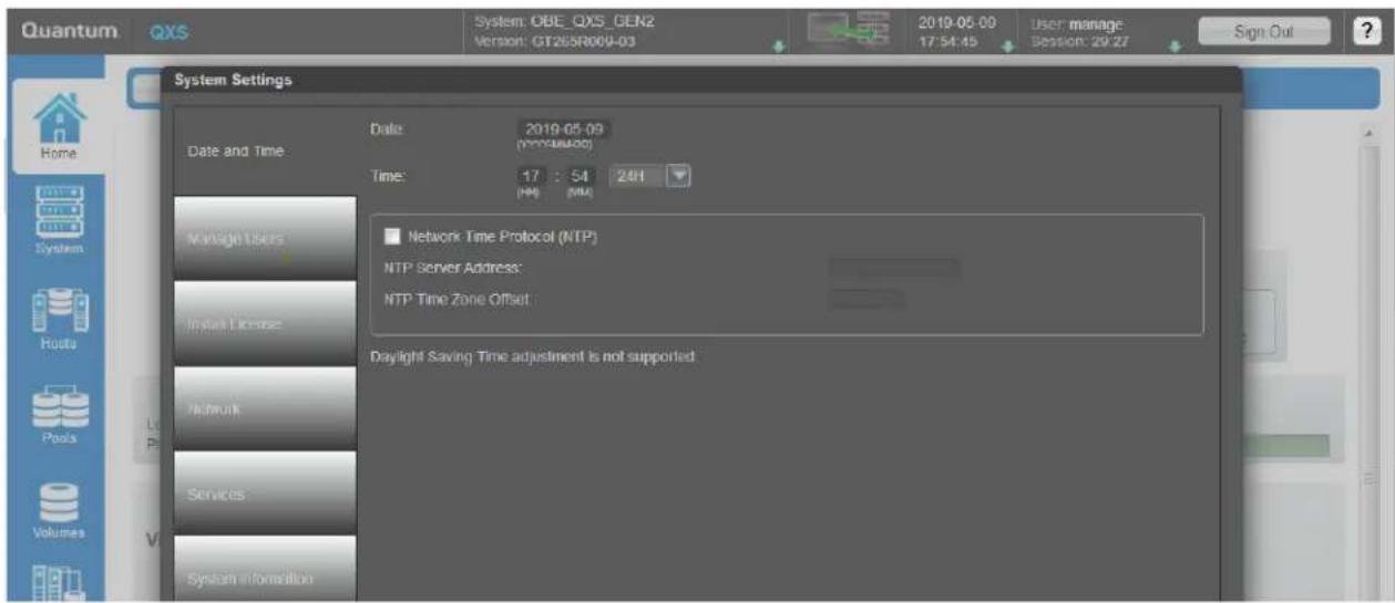
For additional information, click on the "Help" icon which is the "?" at the top-right of the screen and the following screen appear.
NOTE: Notice there are hyperlinks that will take you directly to help content corresponding to the eight tabs on the left side of System Settings panel.
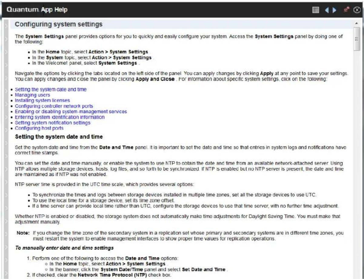
3 Set the date and time so that entries in system logs and notifications have correct time stamps.
- You can set the date and time manually or configure the system to use NTP to obtain them from a network-attached server.
- When NTP is enabled, and if an NTP server is available, the system time and date can be obtained from the NTP server.
- This allows multiple storage devices, hosts, and log files to be synchronized.
Click on "Manage Users".
To secure the storage system, set a new password for each default user.
• A password is case sensitive and can have 8-32 characters.
- If the password contains only printable ASCII characters, then it must contain at least one uppercase character, one lowercase character, and one non-alphabetic character.
- A password can include printable UTF-8 characters except for the following: a space or ", < > \
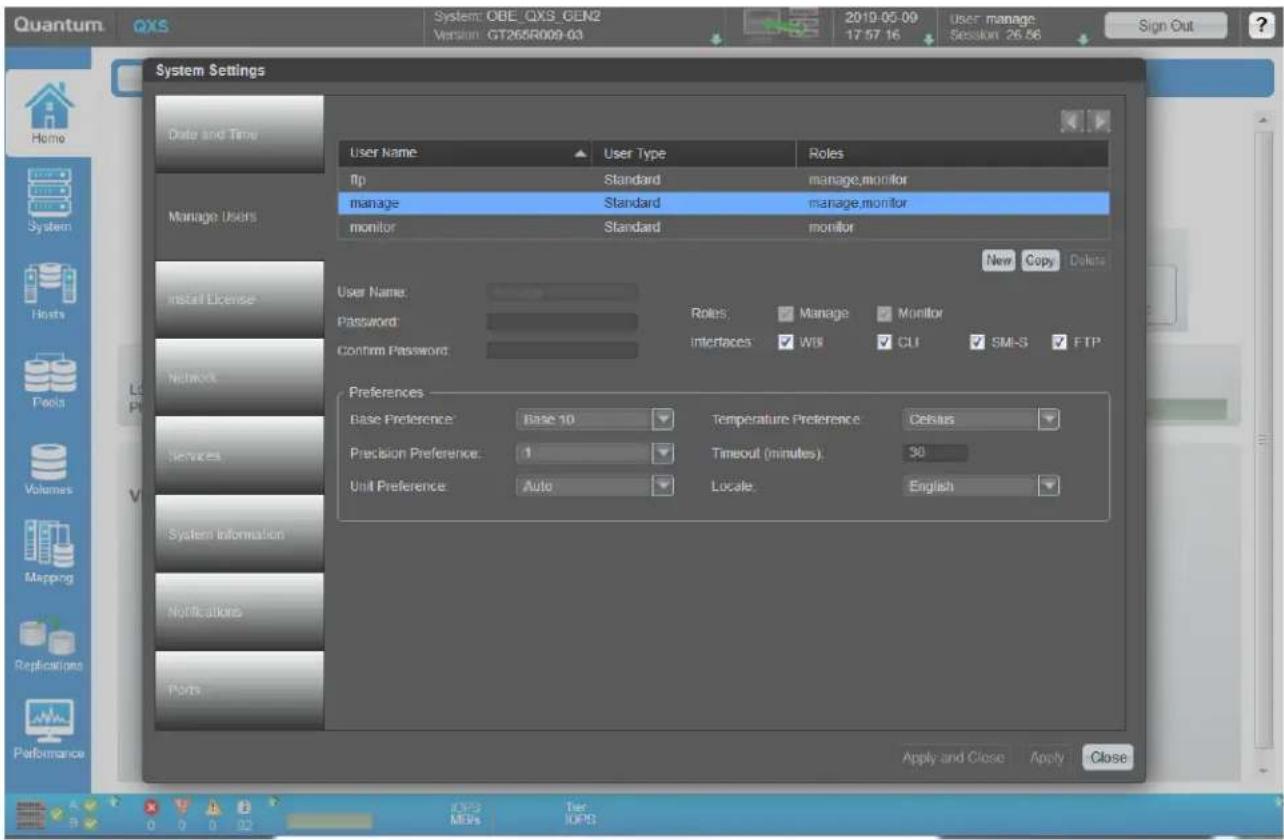
4 Click on "Install License" to verify the licenses that were purchased.
NOTE: The Virtualization license is installed at the factory and should be enabled on this screen.
If the bundled license is bought at the initial purchase of the system, the Licensed Snapshots, Performance Tier (Tiering), and Replication (Async) will be enabled at the factory.
If a permanent license is not installed and you want to try these features before buying a permanent license, you can create a one-time temporary license. The temporary license will expire 60 days from the time it is created.
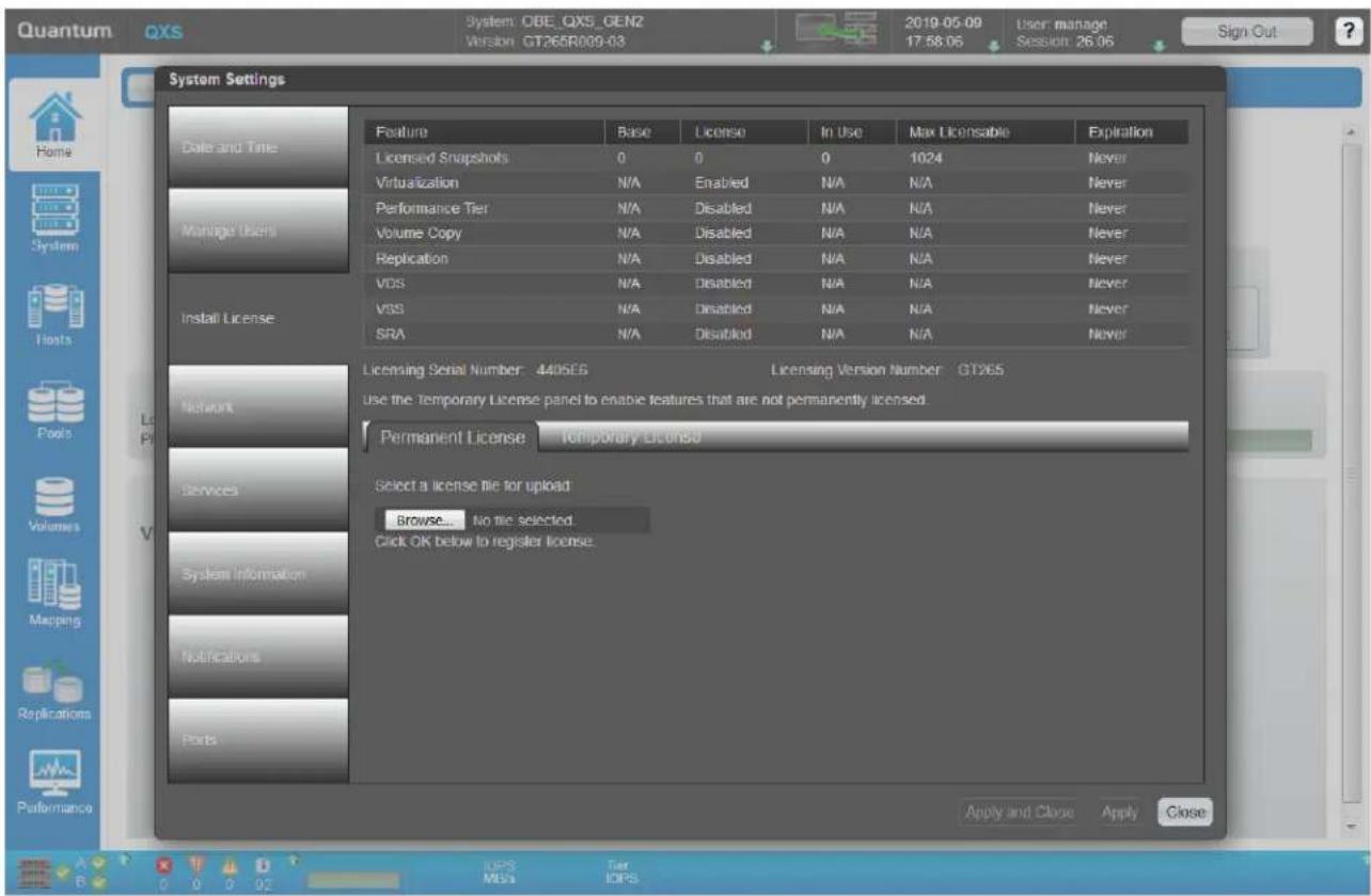
5 Click on "Network" to set up the IP addresses.
You can change addressing parameters for the network port in each controller module.
- You can set static IP values or use DHCP.
- When setting static IP values, you can use either IPv4 or IPv6 format.
In DHCP mode, the system obtains values for the network port IP address, subnet mask, and gateway from a DHCP server if one is available.
- If a DHCP server is unavailable, current addressing is unchanged.
- You must have some means of determining what addresses have been assigned, such as the list of bindings on the DHCP server.
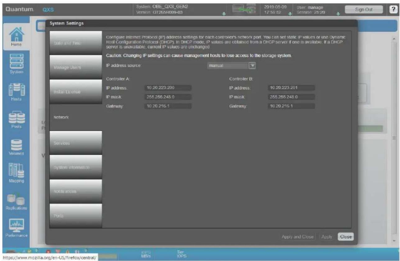
6 Click on "Services" to enable or disable management services.
- You can enable or disable management services to limit the ways in which users and host-based management applications can access the storage system.
- Network management services operate outside the data path and do not affect host I/O to the system.
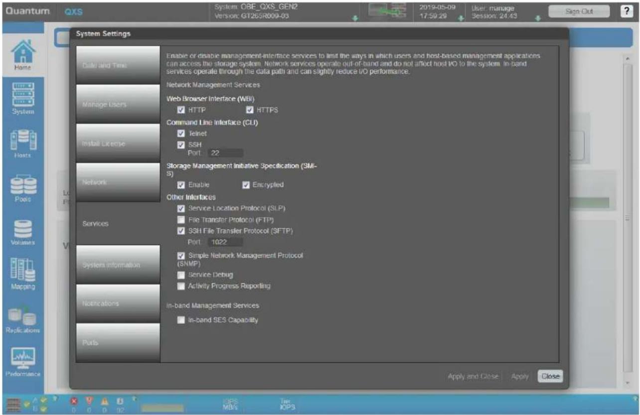
7 Click on "System Information" to enter the system name, contact, location, and information (description) values.
- The name is shown in the browser title bar or tab.
- The name, location, and contact are included in event notifications.
- All four values are recorded in system debug logs for reference by service personnel.
• Each value can include a maximum of 79 bytes, using all characters except the following: "< > \
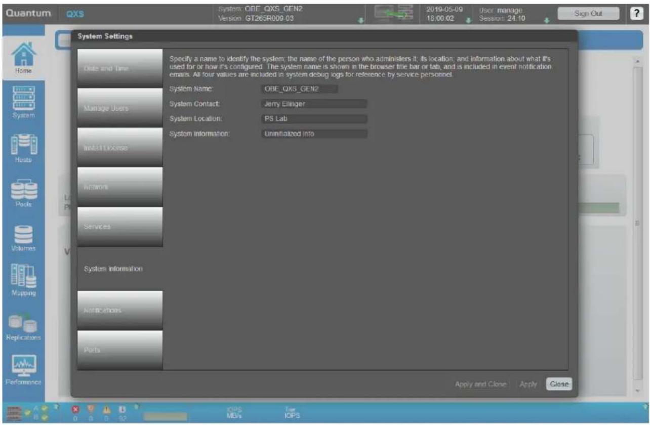
8 Click on "Notifications" to enable the system to send notifications.
- You can enable the system to send notifications to SNMP trap hosts and email addresses when events occur in the system.
- You can also enable the managed logs feature, which transfers log data to a log-collection system.
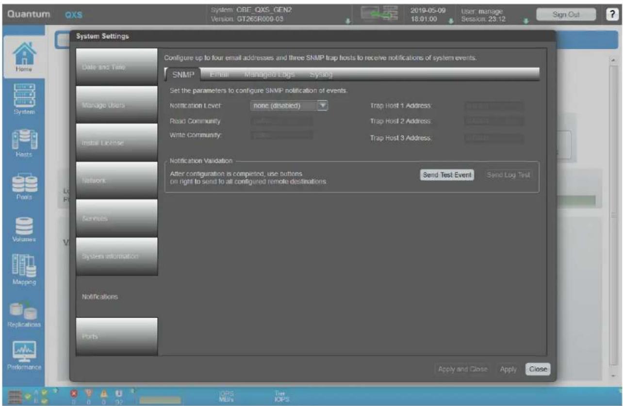
9 Click on "Ports" to enable the system to communicate with hosts or with remote systems.
- To enable the system to communicate with hosts or with remote systems having FC or iSCSI interfaces, you can configure the system's host-interface options.
- If the current settings are correct, port configuration is optional.
NOTE: When you change any setting in the System Settings panel, the Apply and Close and the Apply buttons will become active. To save your changes and continue changing other settings click the Apply button. To save your changes and exit click the Apply and Close button.
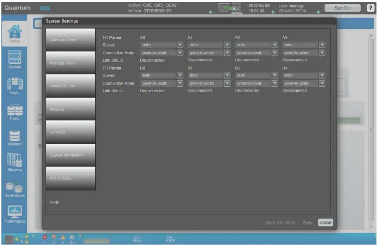
Setting Network Port IP Addresses Using DHCP
In DHCP mode, network port IP address, subnet mask, and gateway values are obtained from a DHCP server if one is available. If a DHCP server is unavailable, current addressing is unchanged. You must have some means of determining what addresses have been assigned, such as the list of bindings on the DHCP server.
Setting Network Port IP Addresses Using CLI Port and Cable
If you did not use DHCP to set network port IP values, set them manually as described below. If you are using the USB CLI port and cable, you will need to enable the port for communication. See also Using CLI Port and Cable/Known Issues in Windows on page 226.
Network ports on controller module A and controller module B are configured with the following default values:
• Network port IP address: 10.0.0.2 (controller A), 10.0.0.3 (controller B)
• IP subnet mask: 255.255.255.0
• Gateway IP address: 10.0.0.1
If the default IP addresses are not compatible with your network, you must set an IP address for each network port using the CLI embedded in each controller module. The CLI enables you to access the system using the USB (Universal Serial Bus) communication interface and terminal emulation software.
NOTE: If you are using the mini USB CLI port and cable, see Rear Panel USB Ports on page 223:
- Unless using Win 10 or Server 2016, Windows customers should download and install the device driver as described in Obtaining the Software Download on page 225.
- Linux customers should prepare the USB port as described in Setting Parameters for Device Driver on page 226.
Use the CLI commands described in the steps below to set the IP address for the network port on each controller module.
Once new IP addresses are set, you can change them as needed using the disk management utility (GUI). Be sure to change the IP address before changing the network configuration. See the QXS 12G Disk Management Utility User Guide for more information concerning the web-based storage management application.
1 From your network administrator, obtain an IP address, subnet mask, and gateway address for controller A and another for controller B.
Record these IP addresses so you can specify them whenever you manage the controllers using the disk management utility (GUI) or the CLI.
2 Use a USB cable to connect controller A to a USB port on a host computer. The USB mini 5 male connector plugs into the CLI port as shown in Figure 84 (generic controller module is shown).
Figure 84 Connecting USB Cable to CLI Port
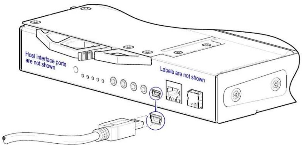
3 Enable the CLI port for subsequent communication:
- Linux customers should enter the command syntax provided in Setting Parameters for Device Driver on page 226.
- Windows customers should locate the downloaded device driver described in Obtaining the Software Download on page 225, and follow the instructions provided for proper installation.
4 Start and configure a terminal emulator, such as HyperTerminal or VT-100, using the display settings used in Table 10, and the connection settings in Table 11 (also, see the note following this procedure).
Table 10 Terminal Emulator Display Settings
| Parameter Value | |
| Terminal emulation mode VT-100 or ANSI (for color support) | |
| Front Terminal | |
| Translations None | |
| Columns 80 | |
Table 11 Terminal Emulator Connection Settings
| Parameter Value | |
| Connector | COM3 (for example) ^1,2 |
| Baud rate 115,200 | |
| Data bits 8 | |
| Parity | None |
| Stop bits | 1 |
| Flow control | None |
^1 Your server or laptop configuration determines which COM port is used for Disk Array USB Port.
^2 Verify the appropriate COM port for use with the CLI.
5 In the terminal emulator, connect to controller A.
6 Press Enter to display the CLI prompt (#).
The CLI displays the system version, Management Controller version, and login prompt.
a At the login prompt, enter the default user manage.
b Enter the default password !manage.
If the default user or password—or both—have been changed for security reasons, enter the secure login credentials instead of the defaults shown above.
7 At the prompt, enter the following CLI command to set the values you obtained in step 1 for each network port, first for controller A, and then for controller B:
set network-parameters ip address netmask netmask gateway gateway controller a|b
where:
- address is the IP address of the controller
• netmask is the subnet mask
• gateway is the IP address of the subnet router - a|b specifies the controller whose network parameters you are setting
For example:
# set network-parameters ip 192.168.0.10 netmask 255.255.255.0 gateway 192.168.0.1 controller a
set network-parameters ip 192.168.0.11 netmask 255.255.255.0 gateway
192.168.0.1 controller b
8 Enter the following CLI command to verify the new IP addresses:
show network-parameters
Network parameters, including the IP address, subnet mask, and gateway address are displayed for each controller.
9 Use the ping command to verify connectivity to the gateway address.
For example:
# ping 192.168.0.1
A success message will say that the remote computer responded with 4 packets.
10 In the host computer's command window, type the following command to verify connectivity, first for controller A and then for controller B:
ping controller-IP-address
If you cannot access your system for at least three minutes after changing the IP address, you might need to restart the Management Controller(s) using the serial CLI.
When you restart a Management Controller, communication with it is temporarily lost until it successfully restarts.
Enter the following CLI command to restart the Management Controller in both controllers: restart mc both
IMPORTANT: When configuring an iSCSI system or a system using a combination of FC and iSCSI SFPs, do not restart the Management Controller or exit the terminal emulator session until configuring the CNC ports as described in Change CNC Port Mode on page 98.
11 When you are done using the CLI, exit the emulator.
12 Retain the IP addresses (recorded in step 1) for accessing and managing the controllers using the disk management utility (GUI) or the CLI.
NOTE: Using HyperTerminal with the CLI on a Microsoft Windows host:
- On a host computer connected to a controller module's mini-USB CLI port, incorrect command syntax in a HyperTerminal session can cause the CLI to hang.
To avoid this problem, use correct syntax, use a different terminal emulator, or connect to the CLI using telnet rather than the mini-USB cable.
- Be sure to close the HyperTerminal session before shutting down the controller or restarting its Management Controller. Otherwise, the host's CPU cycles may rise unacceptably.
If communication with the CLI is disrupted when using an out-of-band cable connection, communication can sometimes be restored by disconnecting and reattaching the mini-USB CLI cable as described in step 2 and Figure 84 on page 95.
Change CNC Port Mode
CAUTION: The QXS-312 12G, QXS-324 12G, QXS-412 12G, QXS-424 12G, and QXS-484 12G ships with SFP installed (FC or iSCSI, per customer order). Using FC SFPs and iSCSI SFPs in combination is not supported.
While the USB cable is still connected and the terminal emulator session remains active, perform the following steps to change the CNC port mode from the default setting (FC) to iSCSI (if needed).
Set CNC Port Mode to iSCSI
To set the CNC port mode for use with iSCSI SFPs, run the following CLI command at the command prompt:
set host-port-mode iSCSI
The command notifies you that it will change host port configuration, stop I/O, and restart both controllers. When asked if you want to continue, enter y to change the host port mode to use iSCSI SFPs.
Once the set host-port-mode CLI command completes, it will notify you that the specified system host port mode was set, and that the command completed successfully.
Continue with step 11 of Setting Network Port IP Addresses Using CLI Port and Cable on page 94.
Connecting Two Storage Systems to Replicate Volumes
Replication is a licensed feature for disaster recovery. This feature performs asynchronous replication of block-level data from a volume in a primary system to a volume in a secondary system by creating an internal snapshot of the primary volume, and copying the changes to the data since the last replication to the secondary system via FC or iSCSI links.
The two associated standard volumes form a replication set, and only the primary volume (source of data) can be mapped for access by a server. Both systems must be licensed to use the replication feature, and must be connected through switches to the same fabric or network (no direct attach). The server accessing the replication set need only be connected to the primary system. If the primary system goes offline, a connected server can access the replicated data from the secondary system.
Replication configuration possibilities are many, and can be cabled—in switch attach fashion—to support the CNC-based systems on the same network, or on different networks. As you consider the physical connections of your system—specifically connections for replication—keep several important points in mind:
- Ensure that controllers have connectivity between systems, whether the destination system is co-located or remotely located.
- Qualified Converged Network Controller options can be used for host I/O or replication, or both.
- The storage system does not provide for specific assignment of ports for replication. However, this can be accomplished using virtual LANs for iSCSI and zones for FC, or by using physically separate infrastructure. Refer to Multiple Servers/Single Same Network on page 100 for additional information.
- For remote replication, ensure that all ports assigned for replication are able to communicate appropriately with the replication system (see the QXS 12G CLI Reference Guide for more information): by using the query peer-connection CLI command.
- Allow a sufficient number of ports to perform replication.
- This permits the system to balance the load across those ports as I/O demands rise and fall.
- If some of the volumes replicated are owned by controller A and others are owned by controller B, then allow at least one port for replication on each controller module—and possibly more than one port per controller module—depending on replication traffic load.
- For the sake of system security, do not unnecessarily expose the controller module network port to an external network connection.
Conceptual cabling examples are provided addressing cabling on the same network and cabling relative to different networks.
IMPORTANT: The replication feature must be licensed on all systems configured for replication, and the controller module firmware must be compatible on all systems used for replication. See the topic about licensed features in the QXS 12G Disk Management Utility User Guide.
Cabling for Replication
The following sections show example replication configurations for CNC-based RAID chassis.
NOTE: Simplified versions of RAID chassis are used in cabling illustrations to show host ports used for I/O or replication, given that only the external connectors used in the host interface ports differ.
- Replication supports FC and iSCSI host interface protocols.
- The 2U chassis rear panel represents the 2U12/2U24 RAID chassis (4-port) models.
- The 5U chassis rear panel represents the 5U84 RAID chassis (4-port) models.
- Host ports used for replication must use the same protocol (either FC or iSCSI).
- Blue cables show I/O traffic and green cables show replication traffic.
Once the CNC-based systems are physically cabled, see the QXS 12G Disk Management Utility User Guide or online help for information about configuring, provisioning, and using the optional replication feature with out-of-band management.
Host Ports and Replication
QXS-312 12G, QXS-324 12G, QXS-412 12G, QXS-424 12G, and QXS-484 12G RAID chassis controller modules can use qualified SFP options of the same type, or they can use a combination of qualified SFP options supporting different interface protocols. If you use a combination of different protocols, then host ports 0 and 1 are set to FC (either both 16Gb/s or 8Gb/s), and ports 2 and 3 must be set to iSCSI (either both 10GbE or both 1Gb). FC and iSCSI ports can be used to perform I/O or replication.
IMPORTANT: QXS-312 12G, QXS-324 12G, QXS-412 12G, QXS-424 12G, and QXS-484 12G RAID chassis support dual-controller configuration only. If a partner controller fails, the storage system will fail over and run on a single controller module until the redundancy is restored. A controller module must be installed in each slot to ensure sufficient airflow through the chassis during operation.
Each of the following diagrams show the rear panel of two QXS-312 12G, QXS-324 12G, QXS-412 12G, QXS-424 12G, and QXS-484 12G RAID chassis equipped with dual-controller modules. Some of the diagrams show 2U chassis, while others show 5U chassis. The controller modules can use qualified SFP options of the same type, or they can use a combination of qualified SFP options supporting different interface protocols.
IMPORTANT: QXS-312 12G, QXS-324 12G, QXS-412 12G, QXS-424 12G, and QXS-484 12G RAID chassis support FC and iSCSI host interface protocols for host connection or for performing replications.
Multiple Servers/Single Same Network
Figure 85 shows the rear panel of two 2U chassis with I/O and replication occurring on the same physical network. Figure 87 on page 101 shows the rear panel of two 5U chassis with I/O and replication occurring on the same physical network.
With the replication configurations shown in each of these figures, Virtual Local Area Network (VLAN) and zoning could be employed to provide separate networks for iSCSI and FC, respectively. Create a VLAN or zone for I/O and a VLAN or zone for replication to isolate I/O traffic from replication traffic. Either or these configurations would appear physically as a single network, while logically, either configuration would function as multiple networks.
Connecting Two 2U Storage Systems (4-Host Ports) for Replication
Figure 85 provides an illustration of connecting two 2U12/2U24 RAID chassis (4-host ports per controller, storage systems) for replication (multiple servers/one switch/one location)..
Figure 85 Connecting Two 2U Storage Systems (4-Host Ports) for Replication
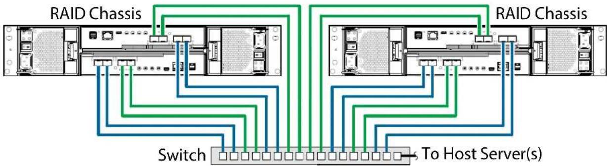
flowchart
graph TD
    A["RAID Chassis"] --> B["Switch"]
    C["RAID Chassis"] --> D["To Host Server(s)"]
    B --> E["Device 1"]
    B --> F["Device 2"]
    B --> G["Device 3"]
    B --> H["Device 4"]
    B --> I["Device 5"]
    B --> J["Device 6"]
    B --> K["Device 7"]
    B --> L["Device 8"]
    B --> M["Device 9"]
    B --> N["Device 10"]
    B --> O["Device 11"]
    B --> P["Device 12"]
    B --> Q["Device 13"]
    B --> R["Device 14"]
    B --> S["Device 15"]
Connecting Two 2U Storage Systems (2-Host Ports) for Replication
Figure 86 provides an illustration of connecting two 2U12/2U24 RAID chassis (2-host ports per controller, storage systems) for replication (multiple servers/one switch/one location)..
Figure 86 Connecting Two 2U Storage Systems (2-Host Ports) for Replication
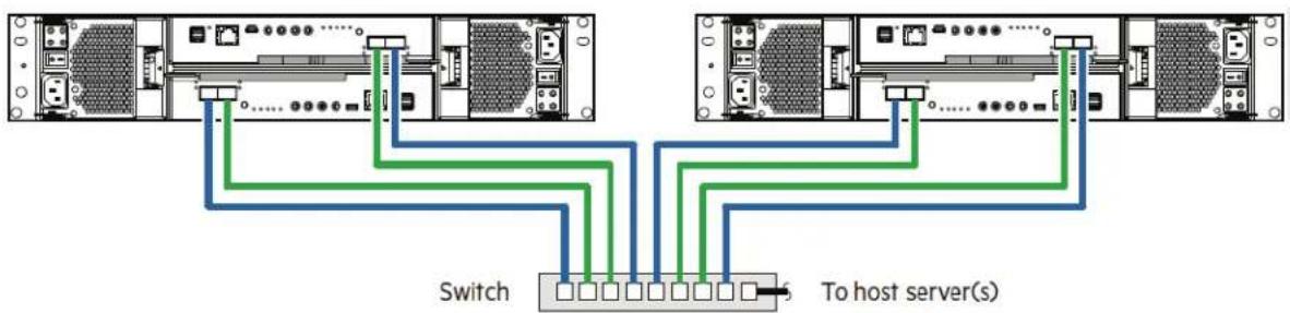
flowchart
graph TD
    A["Server Rack 1"] -->|Switch| B["Server Rack 2"]
    C["Server Rack 3"] -->|Switch| B
    D["Server Rack 4"] -->|Switch| B
    B --> E["To host server(s)"]
    style A fill:#f9f,stroke:#333
    style C fill:#f9f,stroke:#333
    style D fill:#f9f,stroke:#333
    style B fill:#ccf,stroke:#333
    style E fill:#cff,stroke:#333
Connecting Two 5U Storage Systems for Replication
Figure 87 provides an illustration of connecting two 5U84 RAID chassis (storage systems) for replication (multiple servers/one switch/one location)..
Figure 87 Connecting Two 5U Storage Systems for Replication
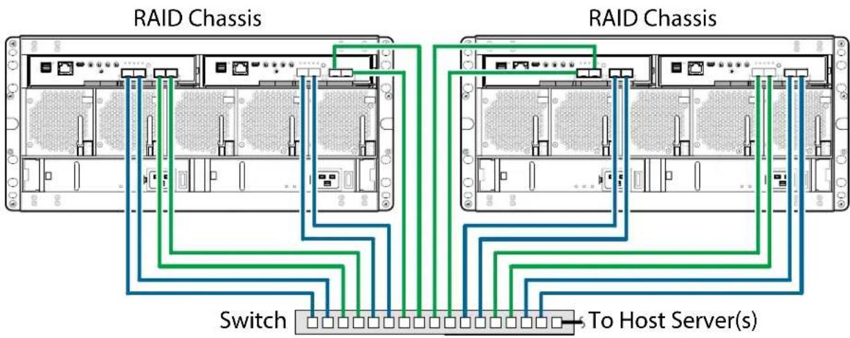
Multiple Servers/Different Networks
Figure 88 (2U) and Figure 90 on page 102 (5U) each show the rear panel of two chassis with I/O and replication occurring on different physical networks. For optimal protection, use three switches to enable host I/O and replication.
Connect two ports from each controller module in the left storage chassis to the left switch. Connect two ports from each controller module in the right storage chassis to the right switch. Connect two ports from each controller module in each chassis to the middle switch. Use multiple switches to avoid a single point of failure inherent to using a single switch, and to physically isolate replication traffic from I/O traffic.
Connecting Two 2U Systems (4-Host Ports) for Replication (Multiple Servers/Switches)
Figure 88 provides an illustration of connecting two 2U12/2U24 RAID chassis (storage systems) for replication (multiple servers/switches/one location)..
Figure 88 Connecting Two 2U Systems (4-Host Ports) for Replication (Multiple Servers/Switches)
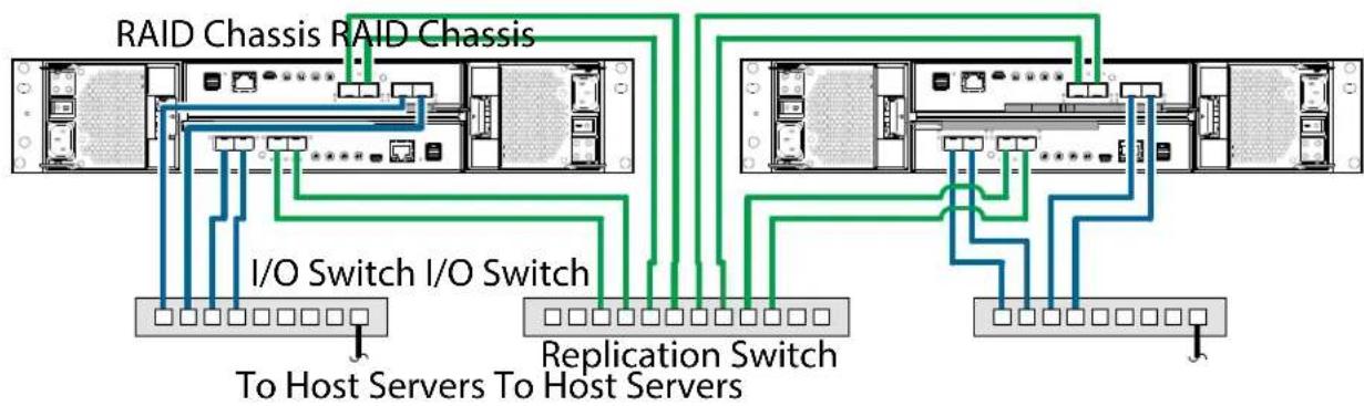
flowchart
graph TD
    A["RAID Chassis"] --> B["I/O Switch"]
    C["RAID Chassis"] --> D["I/O Switch"]
    E["Replication Switch"] --> F["To Host Servers"]
    G["Replication Switch"] --> H["To Host Servers"]
    B --> I["Server 1"]
    B --> J["Server 2"]
    D --> K["Server 3"]
    D --> L["Server 4"]
    F --> M["Server 5"]
    F --> N["Server 6"]
    H --> O["Server 7"]
    H --> P["Server 8"]
Connecting Two 2U Systems (2-Host Ports) for Replication (Multiple Servers/Switches)
Figure 89 provides an illustration of connecting two 2U12/2U24 RAID chassis (storage systems) for replication (multiple servers/switches/one location)..
Figure 89 Connecting Two 2U Systems (2-Host Ports) for Replication (Multiple Servers/Switches)
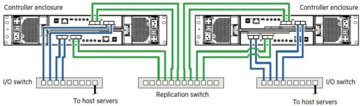
flowchart
graph TD
    A["Controller enclosure"] --> B["I/O switch"]
    A --> C["Replication switch"]
    A --> D["Controller enclosure"]
    B --> E["To host servers"]
    C --> F["To host servers"]
    D --> G["I/O switch"]
Connecting Two 5U Systems for Replication (Multiple Servers/Switches)
Figure 90 provides an illustration of connecting two 5U84 RAID chassis (storage systems) for replication (multiple servers/switches/one location).
Figure 90 Connecting Two 5U Systems for Replication (Multiple Servers/Switches)
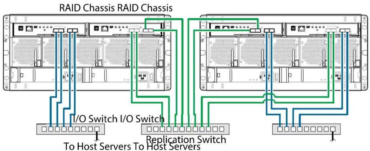
Multiple Servers/Different Networks/Multiple Switches
Figure 91 (2U) and Figure 93 on page 104 (5U) each show the rear panel of two chassis with I/O and replication occurring on different networks. The I/O traffic occurs on the SAN, and the replication traffic occurs on the Ethernet WAN.
Connecting Two 2U Systems (4-Host Ports) for Replication (Multiple Servers/Switches/Locations)
Figure 91 provides an illustration of connecting two 2U12/2U24 RAID chassis (storage systems) for replication (multiple servers/switches/two locations).
Figure 91 Connecting Two 2U Systems (4-Host Ports) for Replication (Multiple Servers/Switches/Locations)
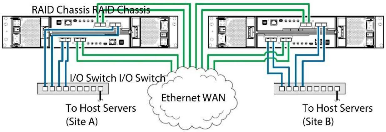
flowchart
graph TD
    A["RAID Chassis RAID Chassis"] --> B["I/O Switch I/O Switch"]
    B --> C["To Host Servers (Site A)"]
    B --> D["Ethernet WAN"]
    D --> E["To Host Servers (Site B)"]
    A --> F["RAID Chassis RAID Chassis"]
    F --> G["I/O Switch I/O Switch"]
    G --> H["To Host Servers (Site A)"]
    G --> I["Ethernet WAN"]
Connecting Two 2U Systems (2-Host Ports) for Replication (Multiple Servers/Switches/Locations)
Figure 92 provides an illustration of connecting two 2U12/2U24 RAID chassis (storage systems) for replication (multiple servers/switches/two locations).
Figure 92 Connecting Two 2U Systems (2-Host Ports) for Replication (Multiple Servers/Switches/Locations)
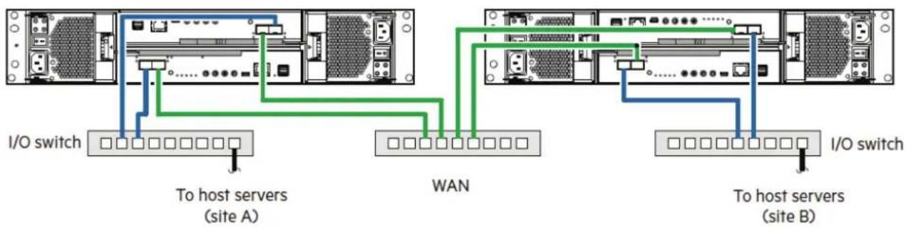
flowchart
graph TD
    subgraph I/O switch
        A["Server"] -->|I/O switch| B["To host servers (site A)"]
        B --> C["WAN"]
    end
    subgraph WAN
        D["Server"] -->|I/O switch| E["To host servers (site B)"]
        E --> F["To host servers (site A)"]
        F --> G["WAN"]
    end
Connecting Two 5U Systems for Replication (Multiple Servers/Switches)
Figure 93 provides an illustration of connecting two 5U84 RAID chassis (storage systems) for replication (multiple servers/switches/two locations).
Figure 93 Connecting Two 5U Systems for Replication (Multiple Servers/Switches)
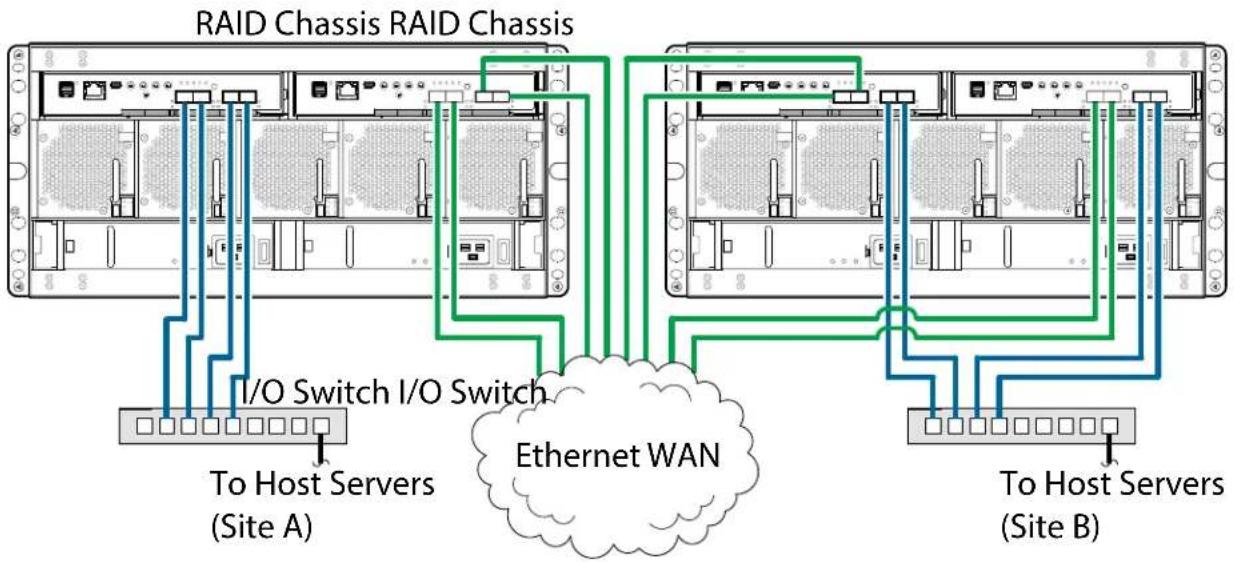
flowchart
graph TD
    A["RAID Chassis RAID Chassis"] -->|I/O Switch I/O Switch| B["Ethernet WAN"]
    B --> C["To Host Servers (Site A)"]
    B --> D["To Host Servers (Site B)"]
NOTE: The diagrams shown in Figure 91 and Figure 93 represent two branch offices cabled to enable disaster recovery and backup. In case of failure at either the local site or the remote site, you can fail over the application to the available site.

natural_image
Abstract pattern of blue squares arranged in a grid on white background (no text or symbols)Chapter 4
Operation
This chapter provides information for the following QXS 12G systems:
• QXS-312 12G: 12-Drive (2-Port: FC or iSCSI)
• QXS-324 12G: 24-Drive (2-Port: FC or iSCSI)
• QXS-412 12G: 12-Drive (4-Port: FC or iSCSI)
• QXS-424 12G: 24-Drive (4-Port: FC or iSCSI)
• QXS-484 12G: 84-Drive (4-Port: FC or iSCSI)
Before You Begin
Before powering on the storage system, make sure that all modules are firmly seated in their correct slots. Verify that you have successfully completed the sequential Installation Checklist on page 55. Once you have completed steps 1 through 10, you can access the management interfaces using your web-browser to complete the system setup.
Powering On/Powering Off
CAUTION: Do not operate the storage system until the ambient temperature is within the specified operating range described in QXS 2U/5U Environmental Requirements on page 215.
Install all drives in the RAID and/or expansion chassis so the controller can identify and configure them when powering on the system
If the drive modules have been recently installed, make sure they have had time to adjust to the environmental conditions before they are used with production data for I/O.
NOTE: Always power on all of the attached expansion chassis first and then power on the RAID chassis. This ensures the RAID chassis recognizes all the applicable attached expansion chassis and its applicable CRUs.
This section provides the following information:
- Guidelines
• Powering On the 2U12 and/or 2U24 System
• Powering Off the 2U12 and/or 2U24 System
• Powering On the 5U84 System
• Powering Off the 5U84 System
Guidelines
Guidelines for consideration when powering chassis on and off include.
- Remove the AC cord before inserting or removing a PSU.
- Move the PSU switch to the off position before connecting or disconnecting the AC power cord.
- Allow 15 seconds between powering off and powering on the PSU.
- Allow 15 seconds before powering on one PSU in the system, and powering off another PSU.
- Never power off a PSU while any amber LED is lit on the partner PSU.
- The chassis must be left in a power on state for 30 seconds following resumption from standby before the chassis can be placed into standby again (applies to 5U84 only).
- Although the chassis supports standby, the expansion chassis shuts off completely during standby and cannot receive a user command to power back on.
- An AC power cycle is the only method to return the 5U84 to full power from standby.
Powering On the 2U12 and/or 2U24 System
This section provides the following information:
• Powering On the 2U12 and/or 2U24 Expansion Chassis
• Powering On the 2U12 and/or 2U24 RAID Chassis
Powering On the 2U12 and/or 2U24 Expansion Chassis
NOTE: Powering on the 2U12 and 2U24 expansion chassis is the identical process.
To power on the expansion chassis:
CAUTION: Refer to Figure 94 and Figure 95 and verify that all expansion chassis and RAID chassis power switches are in the off position (0) to ensure none of the chassis power on before needed.
1 Locate the power supply units (PSU0 and PSU1) on the rear of the 2U12/2U24 expansion chassis in Figure 94.
Figure 94 2U12/2U24 Expansion Chassis (Rear View)
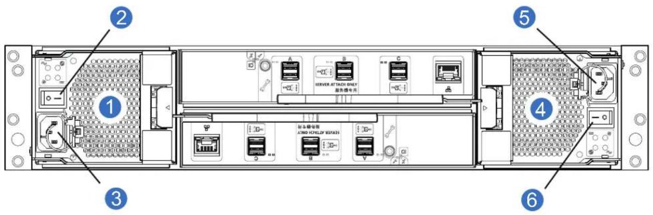
1 PSU0 2 PSU0 Power Switch
3 PSU0 Power Receptacle 4 PSU1
5 PSU1 Power Receptacle 6 PSU1 Power Switch
2 Plug the power cords into the power cord receptacles on the rear of the expansion chassis.
3 Plug the other end of the power cords into the rack power source.
NOTE: Each expansion chassis takes approximately 3 minutes to power on (drives to spin up and/or come online).
4 Turn on (1) the PSU0 power switch and then turn on the PSU1 power switch.
- Expansion chassis powers on within 3 minutes.
- While the expansion chassis power up, their LEDs blink. After the LEDs stop blinking—if no LEDs on the front and back of the chassis are amber—the power-on sequence is complete, and no faults have been detected.
- The System Power LED on the 2U Ops panel should be lit green when the chassis power is activated.
- See 2U Chassis Ops Panel LEDs on page 117 for details pertaining to 2U Ops panel LEDs and related fault conditions.
NOTE: Repeat these steps for any other expansion chassis within this configuration.
Powering On the 2U12 and/or 2U24 RAID Chassis
To power on the RAID chassis:
1 Locate the power supply units (PSU0 and PSU1) on the rear of the 2U12/2U24 RAID chassis. Representative system shown in Figure 95.
Figure 95 2U12/2U24 Representative RAID Chassis (Rear View)
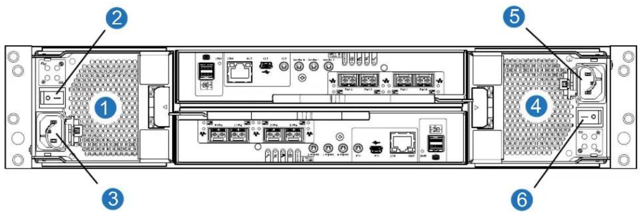
1 PSU0 2 PSU0 Power Switch
3 PSU0 Power Receptacle 4 PSU1
5 PSU1 Power Receptacle 6 PSU1 Power Switch
2 Plug the power cords into the power cord receptacles on the rear of the RAID chassis.
3 Plug the other end of the power cords into the rack power source.
4 Turn on (1) the PSU0 power switch and then turn on the PSU1 power switch. RAID chassis powers on within 3 minutes.
- While the expansion chassis power up, their LEDs blink. After the LEDs stop blinking—if no LEDs on the front and back of the chassis are amber—the power-on sequence is complete, and no faults have been detected.
- The System Power LED on the 2U Ops panel should be lit green when the chassis power is activated.
- See 2U Chassis Ops Panel LEDs on page 117 for details pertaining to 2U Ops panel LEDs and related fault conditions.
Powering Off the 2U12 and/or 2U24 System
NOTE: Powering off the 2U12 and 2U24 system is the identical process.
1 Stop all I/O from hosts to the system (see Stopping I/O on page 179).
2 Shut down both controllers using either method described below:
- Use the Disk Management Utility to shut down both controllers, as described in the QXS 12G Disk Management Utility User Guide.
- Use the CLI to shut down both controllers, as described in the QXS 12G CLI Reference Guide.
3 On the RAID chassis complete the following:
a Turn off (0) the PSU0 power switch and then turn off the PSU1 power switch.
b Disconnect the power cord's male plug from the power source.
c Disconnect the power cord's female plug from the power cord receptacles on PSU0 and PSU1.
4 On the expansion chassis (all attached in this configuration) complete the following:
a Turn off (0) the PSU0 power switch and then turn off the PSU1 power switch.
b Disconnect the power cord's male plug from the power source.
c Disconnect the power cord's female plug from the power cord receptacles on PSU0 and PSU1.
Powering On the 5U84 System
This section provides the following information:
• Powering On the 5U84 Expansion Chassis
• Powering On the 5U84 RAID Chassis
Powering On the 5U84 Expansion Chassis
To power on the expansion chassis:
CAUTION: Refer to Figure 96 and Figure 97 and verify that all expansion chassis and RAID chassis power switches are in the off position (0) to ensure none of the chassis power on before needed.
1 Locate the power supply units (PSU0 and PSU1) on the rear of the 5U84 expansion chassis in Figure 96.
Figure 96 5U84 Expansion Chassis (Rear View)
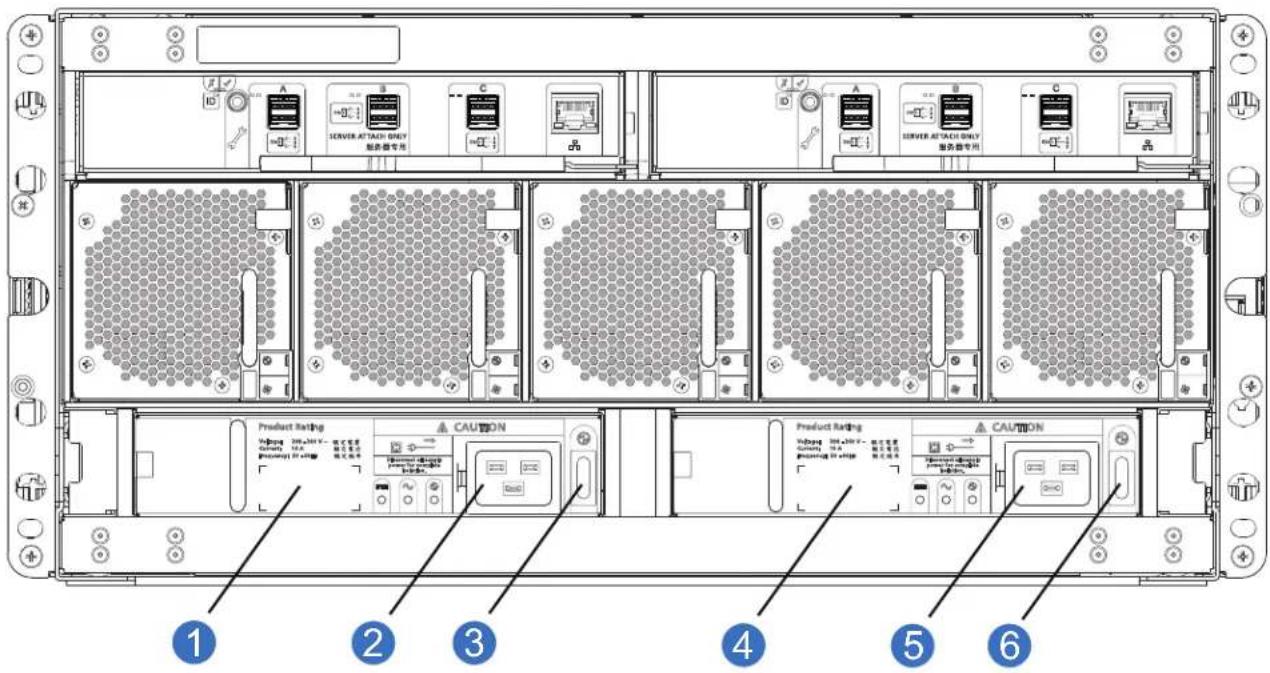
2 Plug the power cords into the power cord receptacles on the rear of the expansion chassis.
3 Plug the other end of the power cords into the rack power source.
NOTE: Each expansion chassis takes approximately 3 minutes to power on (drives to spin up and/or come online).
4 Turn on (1) the PSU0 power switch and then turn on the PSU1 power switch.
- Expansion chassis powers on within 3 minutes.
- While the expansion chassis power up, their LEDs blink. After the LEDs stop blinking—if no LEDs on the front and back of the chassis are amber—the power-on sequence is complete, and no faults have been detected.
- The Power on/Standby LED on the 5U Ops panel should be lit green when the chassis power is activated.
- See 5U Chassis Ops Panel LEDs on page 127 for details pertaining to 5U84 Ops panel LEDs and related fault conditions.
NOTE: Repeat these steps for any other expansion chassis within this configuration.
Powering On the 5U84 RAID Chassis
To power on the RAID chassis:
1 Locate the power supply units (PSU0 and PSU1) on the rear of the 5U84 RAID chassis. Representative system shown in Figure 97.
Figure 97 5U84 Representative RAID Chassis (Rear View)
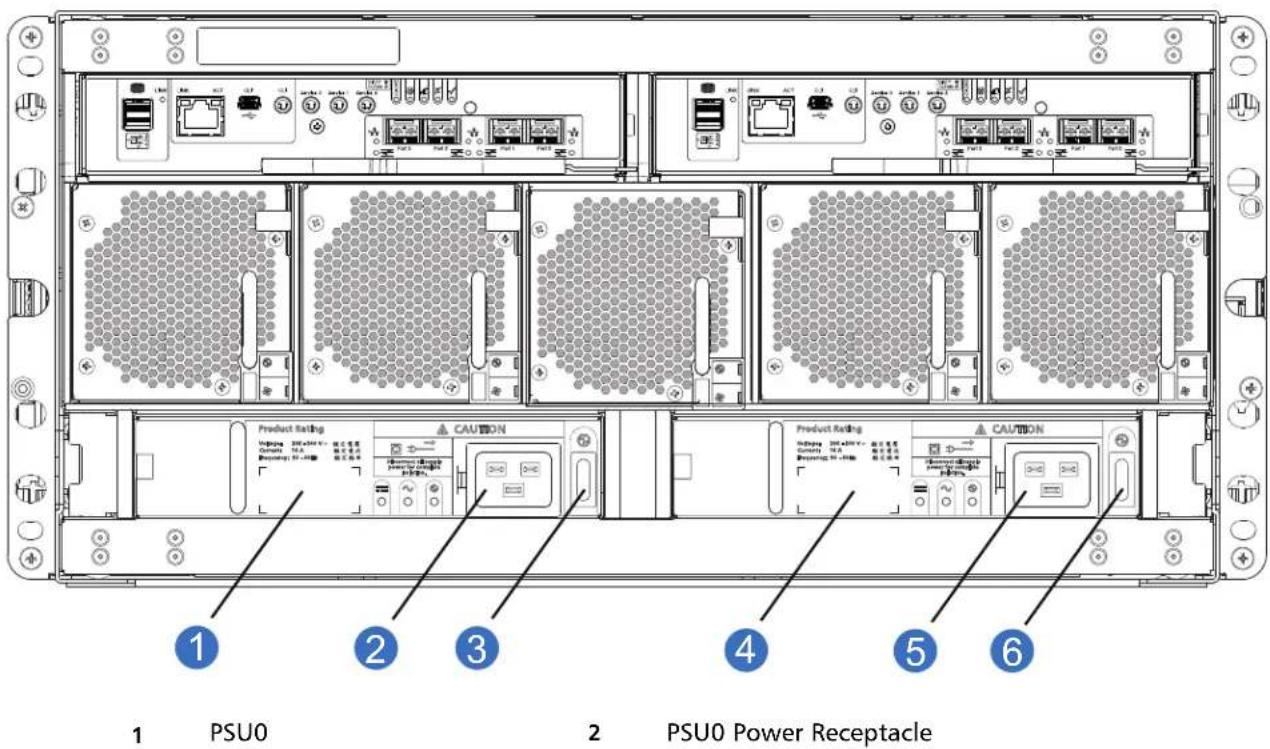
3 PSU0 Power Switch 4 PSU1
5 PSU1 Power Receptacle 6 PSU1 Power Switch
2 Plug the power cords into the power cord receptacles on the rear of the RAID chassis.
3 Plug the other end of the power cords into the rack power source.
4 Turn on (1) the PSU0 power switch and then turn on the PSU1 power switch. RAID chassis powers on within 3 minutes.
- RAID chassis powers on within 3 minutes.
- While the RAID chassis powers up, the LEDs blink. After the LEDs stop blinking—if no LEDs on the front and back of the chassis are amber—the power-on sequence is complete, and no faults have been detected.
- The Power on/Standby LED on the 5U Ops panel should be lit green when the chassis power is activated.
- See 5U Chassis Ops Panel LEDs on page 127 for details pertaining to 5U84 Ops panel LEDs and related fault conditions.
Powering Off the 5U84 System
1 Stop all I/O from hosts to the system (see Stopping I/O on page 179).
2 Shut down both controllers using either method described below:
- Use the Disk Storage Management Utility to shut down both controllers, as described in the QXS 12G Disk Storage Management Utility Users Guide.
- Use the CLI to shut down both controllers, as described in the QXS 12G CLI Reference Guide.
3 On the RAID chassis complete the following:
a Turn off (0) the PSU0 power switch and then turn off the PSU1 power switch.
b Disconnect the power cord's male plug from the power source.
c Disconnect the power cord's female plug from the power cord receptacles on PSU0 and PSU1.
4 On the expansion chassis (all attached in this configuration) complete the following:
a Turn off (0) the PSU0 power switch and then turn off the PSU1 power switch.
b Disconnect the power cord's male plug from the power source.
c Disconnect the power cord's female plug from the power cord receptacles on PSU0 and PSU1.
Operator's (Ops) Panel LEDs
Once the chassis has successfully powered on, you can observe its Ops panel—located on the left ear of the front panel—for LED behavior reflecting chassis status. Refer to the appropriate Ops panel figure/table from the options below for descriptions of chassis status LEDs and related fault conditions.
- For 2U12 and 2U24 chassis, see 2U Operator's (Ops) Panel on page 30.
• For 5U84 chassis, see 5U Chassis Ops Panel on page 32.
Unit Identification Number
The Unit Identification Display (UID) is a dual seven segment display that is used to provide feedback to the user. Its primary purpose is to display an chassis UID number to assist in setting up, monitoring, and managing storage systems comprised of multiple chassis.
The UID is stored in the chassis VPD and is used by management interfaces (CLI and the disk management utility, GUI). The UID can drive all seven of the segments, plus the dot/decimal point in each character of the display.
Software/SES
The chassis UID number can be read and set through the management interfaces and SES.
Disk Drive LEDs
Disk Modules Used in 2U Chassis
Each drive module includes two LEDs (green and amber) as shown in 5U Chassis DDIC LEDs on page 129.
- In normal operation, the green LED will be on and will blink as the drive operates.
-
In normal operation, the amber LED state will be:
-
Off if a disk is not present
- Off as the disk successfully operates
- On if there is a disk fault
DDICs Used in 5U Chassis
Each disk has a single amber drive fault LED as shown in 5U Chassis DDIC LEDs on page 129. If the LED is illuminated, a disk failure condition has occurred. The DDIC should be replaced as soon as possible, using the procedure described in Replacing a 5U84 DDIC on page 190, while adhering to guidelines provided in Populating 5U84 Drawers on page 193.
Accessing Disk Management Utility (GUI)
Upon completing the hardware installation, you can access the controller module's web-based management interface—Disk Management Utility (GUI)—to configure, monitor, and manage the storage system. Invoke your web browser and enter the IP address of the controller module's network port in the address field, then press Enter. To sign-in to the disk management utility (GUI), use the default user name manage and password !manage. If the default user name or password—or both—have been changed for security reasons, enter the secure login credentials instead of the defaults shown above. This brief sign-in discussion assumes proper web browser setup.
Getting Started
For detailed information about accessing and using the Disk Management Utility (GUI), see the topic about getting started in the QXS 12G Disk Management Utility User Guide.
In addition to summarizing the processes to configure and provision a new system for the first time, the getting started topics provide instructions for signing in to the Disk Management Utility (GUI), introduce key system concepts, address browser setup, and provide tips for using the main window and the help window.
After signing-in to the Disk Management Utility (GUI), you can use online help as an alternative to consulting the QXS 12G Disk Management Utility User Guide.
Configuring and Provisioning the Storage System
Once you have familiarized yourself with the Disk Management Utility (GUI), use the interface to configure and provision the storage system. If you are licensed to use the optional replication feature, you may also need to set up the storage systems for replication. Refer to the following topics within the QXS 12G Disk Management Utility User Guide or online help:
- Getting Started
- Configuring the System
- Provisioning the System
• Using the Optional Replication Feature
NOTE: See the topic about licensed features in the QXS 12G Disk Management Utility User Guide for instructions about creating a temporary license, or installing a permanent license.
IMPORTANT: If the system is used in a VMware environment, set the system's Missing LUN Response option to use its Illegal Request setting.
To do so, see either the topic about changing the missing LUN response in the QXS 12G Disk Management Utility User Guide, or see the set advanced-settings command topic in the QXS 12G CLI Reference Guide.

natural_image
Abstract pattern of blue squares arranged in a grid with a partial horizontal line and letter T on the right (no text or symbols)Chapter 5
Troubleshoot/Problem Solving
This chapter provides information for the following QXS 12G systems:
• QXS-312 12G: 12-Drive (2-Port: FC or iSCSI)
• QXS-324 12G: 24-Drive (2-Port: FC or iSCSI)
• QXS-412 12G: 12-Drive (4-Port: FC or iSCSI)
• QXS-424 12G: 24-Drive (4-Port: FC or iSCSI)
• QXS-484 12G: 84-Drive (4-Port: FC or iSCSI)
Overview
These procedures are intended to be used only during initial configuration, for the purpose of verifying that hardware setup is successful. They are not intended to be used as troubleshooting procedures for configured systems using production data and I/O.
For further troubleshooting help after setup, and when data is present, contact Quantum at: http://www.quantum.com/ServiceandSupport/Index.aspx
The storage system includes a Storage Enclosure Processor (SEP) and associated monitoring and control logic to enable it to diagnose problems with the chassis power, cooling, and drive systems. Management interfaces allow for provisioning, monitoring, and managing the storage system.
See Fault Isolation methodology on page 134 when conducting system diagnostics.
Initial Start-Up Problems
This section provides information about faulty power cords and host interface problems.
Faulty Power Cords
Check that you have correctly cabled the system. Contact your supplier for replacements if:
• Power cables are missing or damaged.
- Plugs are incorrect.
• Power cables are too short.
Computer Does Not Recognize the Storage System
Complete the following steps:
1 Verify that the interface cables from the RAID chassis to the host computer are fitted correctly.
2 Verify that the drive carrier modules have been correctly installed.
3 Check any visible SAS indicators (RAID chassis, expansion chassis, and HBA).
4 Check HBA BIOS for SAS target visibility.
5 Verify that the operating system device driver has been installed correctly.
NOTE: If the chassis fails initialization, see If the Chassis Does Not Initialize on page 137.
LEDs
LED colors are used consistently throughout the chassis and its components for indicating status:
- Green: good or positive indication
- Blinking green/amber: non-critical condition
- Amber: critical fault
2U Chassis LEDs
This section provides information about the 2U chassis PSU LEDs, Ops panel LEDs, and drive LEDs.
2U Chassis 580W PSU LEDs
Under normal conditions, the PSU OK LEDs will be a constant green. Figure 98 provides an illustration of the PSU LEDs for the RAID or expansion chassis.
Figure 98 2U Chassis PSU LEDs
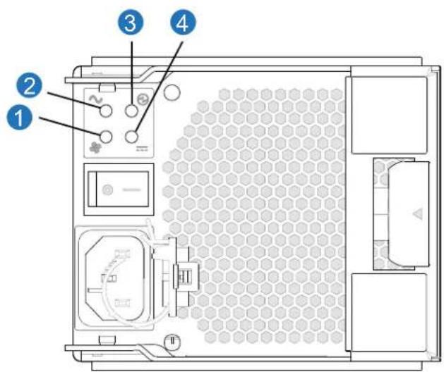
1 Fan Fail LED
2 AC Fail LED
3 PSU OK LED
4 DC Fail LED
When a fault occurs, the colors of the LEDs will display as shown in Table 12.
Table 12 PSU LEDs
| PSU OK(Green) | Fan Fail(Amber) | AC Fail(Amber) | DC Fail(Amber) | Status |
| Off Off Off | Off No AC power to either PSU. | |||
| Off Off On | On No AC power on this PSU. | |||
| On Off Off | Off AC present; PDU working correctly. | |||
| On Off Off | On PSU fan speed is outside acceptable limits. | |||
| O f | f | O | n O f f O f f P S | |
| Off On On | On PSU fault (over temperature, over voltage, over current). | |||
| Off Blinking | Blinking Blinking PSU firmware download is in progress. | |||
2U Chassis Ops Panel LEDs
The Ops panel displays the aggregated status of all the 2U chassis CRU modules. Figure 99 provides an illustration of the Ops panel LEDs for the RAID or expansion chassis.
Figure 99 2U Chassis Ops Panel Functions
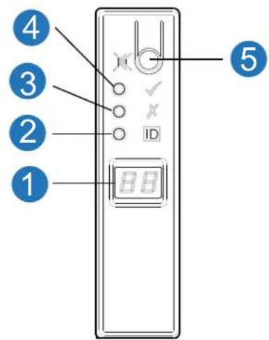
LED
Status
1 Unit Identification Display
Green: Seven segment display: chassis sequence
2 Identity
Blue: Power On (5s) test state
3 Module Fault
Constant or blinking amber: fault present
4 System Power On/Standby
Constant Green: positive indication Constant Amber: fault present
5 Mute Button
Not used
Note: Chassis has a thermal sensor behind the ops panel.
Table 13 Ops Panel LED States
| System Power (Green/Amber) | Module Fault (Amber) | Identity (Blue) | LED Display | Associated LEDs/Alarms Status | |
| On Off Off | -- 5V standby power | present, | overall power failed or switched off | ||
| On On On | On - Ops panel power | on (5s) test | state | ||
| On Off Off | -- Power on, all functions good | ||||
| On On -- PDU fault LEDs, fan fault LEDs Any | PDU fault, fan fault, over or under temperature | ||||
| On On -- SBB (Storage Bridge Bay) | module LEDs | Any SBB module fault | |||
| On On -- No module LEDs | Chassis logical fault | ||||
| On Blinking | -- Module status | LED on SBB | module | Unknown (invalid or mixed) SBB module type installed, I^2C bus failure (inter-SBB communications). EBOD VPD configuration error | |
| On | Blinking | - | - | PDU fault LEDs, fan fault LEDs | Unknown (invalid or mixed) PDU type installed or I^2C bus failure (PDU communications) |
| --- Blinking | - Chassis identification or invalid | ID selected | |||
Actions:
- If the Ops panel Module Fault LED is on, check the module LEDs on the chassis rear panel to narrow the fault to a CRU, a connection, or both.
- Check the event log for specific information regarding the fault, and follow any Recommended Actions.
-
If installing a RAID controller or expansion IOM CRU:
-
Remove and reinstall the CRU per Replacing a 2U RAID Controller or an Expansion IOM on page 177.
- Check the event log for errors.
- If the CRU Fault LED is on, a fault condition is detected.
- Restart this controller from the partner controller using the disk management utility or CLI.
- If the restart does not resolve the fault, remove the RAID controller or expansion IOM and reinsert it.
- If the above actions do not resolve the fault, contact Quantum for assistance.
2U Chassis Drive LEDs
Drive status is monitored by a green LED and an amber LED mounted on the front of each drive carrier module, as shown in Figure 100.
-
In normal operation the green LED will be on, and will flicker as the drive operates.
• In normal operation the amber LED will be: -
Off if there is no drive present.
- Off as the drive operates.
- On if there is a drive fault.
Figure 100 2U Chassis Drive LEDs
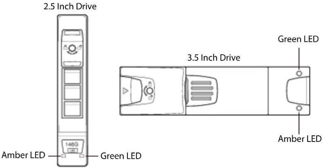
The drive module LED conditions are defined in Table 14
Table 142U Drive LED States
| Drive LED(Green) | Drive LED(Amber) | Status |
| Off Off No drive module installed | ||
| On/Blinking Off Drive module is installed and operational | ||
| On Blinking: 1s on/1s off | SES device identity set | |
| On On SES device fault bit set | ||
Table 14 2U Drive LED States
| Drive LED(Green) | Drive LED(Amber) | Status |
| Off On Power control circuit failure | ||
| Off On RAID array status | The events in which the controller can set this notification are:• Disk group rebuild in progress• Disk group consistency check• Do not remove device• Disk in failed disk group• Aborted disk group reconstruction | |
QXS-312/324 12G Chassis RAID Chassis Controller LEDs
Figure 102 provides an illustration of the RAID chassis controller LEDs. This is a representative example of the controller LEDs. The controller is identical in the QXS-312 12G and QXS-324 12G systems (2 host ports).
Figure 101 CNC (FC and 10GbE SFPs) Controller LEDs
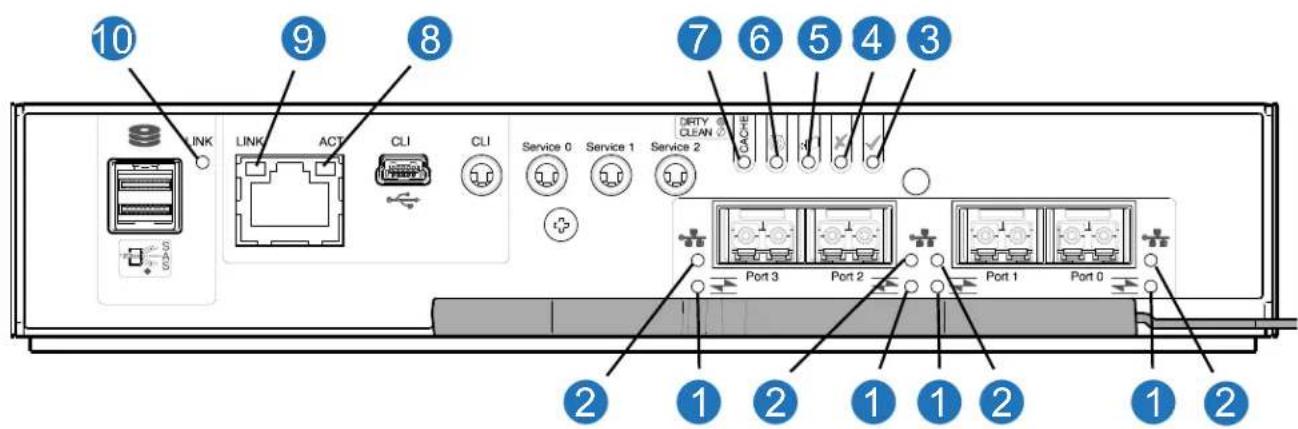
LED Description Definition
Host 4/8/16Gb FC ^1 Link Off — No link detected. Status/Link Activity Green — The port is connected and the link is up. Blinking green — The link has I/O or replication activity.
2 Host 10GbE iSCSI ^2,3 Off — No link detected. Link Status/Link Green — The port is connected and the link is up. Activity Blinking green — The link has I/O or replication activity.
3 OK Green — The controller is operating normally. Blinking green — System is booting. Off — The controller module is not OK, or is powered off.
4 Fault Off — The controller is operating normally. Amber — A fault has been detected or a service action is required. Blinking amber — Hardware-controlled power-up or a cache flush or restore error.
5 OK to Remove Off — The controller is not prepared for removal.
Blue — The controller module is prepared for removal.
6 Identity White — The controller module is being identified.
7 Cache Status ^4 Green — Cache is dirty (contains unwritten data) and operation is normal. The unwritten information can be log or debug data that remains in the cache, so a Green cache status LED does not, by itself, indicate that any user data is at risk or that any action is necessary.
Off — In a working controller, cache is clean (contains no unwritten data). This is an occasional condition that occurs while the system is booting.
Blinking green — A CompactFlash flush or cache self-refresh is in progress, indicating cache activity.
8 Network Port Activity Off — The Ethernet link is not established, or the link is down.
Status ^5 Green — The Ethernet link is up (applies to all negotiated link speeds).
9 Network Port Link Off — Link is up at 10/100base-T negotiated speeds.
Speed ^5 Amber — Link is up and negotiated at 1000base-T.
10 Expansion Port Status Off — The port is empty or the link is down.
Green — The port is connected and the link is up.
Table 16 provides the RAID chassis controller LED states.
Table 15 RAID Chassis Controller LED States
| CRU OK (Green) | CRU Fault (Amber) | External Host Port Activity (Green) | Status |
| On Off - Controller module OK | |||
| Off On - Controller module fault: see Replacing a 2U RAID Controller or an Expansion IOM on page 177 | |||
| -- Off No external host port connection | |||
| -- On External host port connection: no activity | |||
| -- Blinking External host port connection: activity | |||
| Blinking -- System is booting | |||
Actions:
- If the CRU OK LED is blinking, wait for the system to boot.
-
If the CRU OK LED is off, and the controller is powered on, the module has failed.
-
Check that the controller is fully inserted and latched in place, and that the chassis is powered on.
- Check the event log for specific information regarding the failure.
- If the CRU Fault LED is on, a fault condition is detected.
- Restart this controller from the partner controller using the disk management utility or CLI.
- If the restart does not resolve the fault, remove the controller and reinsert it.
- If the above actions do not resolve the fault, contact your supplier for assistance. Controller replacement may be necessary.
QXS-412/424/484 12G Chassis RAID Chassis Controller LEDs
Figure 102 provides an illustration of the RAID chassis controller LEDs. This is a representative example of the controller LEDs. The controller is identical in the QXS-412 12G, QXS-424 12G, and QXS-484 12G systems (4 host ports).
Figure 102 CNC (FC and 10GbE SFPs) Controller LEDs
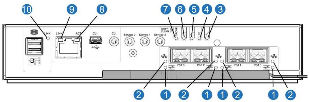
LED Description Definition
Host 4/8/16Gb FC ^1 Link Off — No link detected.
1 Status/Link Activity Green — The port is connected and the link is up. Blinking green — The link has I/O or replication activity.
2 Host 10GbE iSCSI ^2,3 Off — No link detected.
Link Status/Link Green — The port is connected and the link is up.
Activity Blinking green — The link has I/O or replication activity.
3 OK Green — The controller is operating normally. Blinking green — System is booting. Off — The controller module is not OK, or is powered off.
4 Fault Off — The controller is operating normally. Amber — A fault has been detected or a service action is required. Blinking amber — Hardware-controlled power-up or a cache flush or restore error.
5 OK to Remove Off — The controller is not prepared for removal. Blue — The controller module is prepared for removal.
6 Identity White — The controller module is being identified.
7 Cache Status ^4 Green — Cache is dirty (contains unwritten data) and operation is normal. The unwritten information can be log or debug data that remains in the cache, so a Green cache status LED does not, by itself, indicate that any user data is at risk or that any action is necessary.
Off — In a working controller, cache is clean (contains no unwritten data). This is an occasional condition that occurs while the system is booting.
Blinking green — A CompactFlash flush or cache self-refresh is in progress, indicating cache activity.
8 Network Port Activity Off — The Ethernet link is not established, or the link is down. Status ^5 Green — The Ethernet link is up (applies to all negotiated link speeds).
9 Network Port Link Off — Link is up at 10/100base-T negotiated speeds. Speed ^5 Amber — Link is up and negotiated at 1000base-T.
10 Expansion Port Status Off — The port is empty or the link is down. Green — The port is connected and the link is up.
Table 16 provides the RAID chassis controller LED states.
Table 16 RAID Chassis Controller LED States
| CRU OK(Green) | CRU Fault(Amber) | External Host Port Activity(Green) | Status |
| On Off - Controller module OK | |||
| Off On - Controller module fault: see Replacing a 2U RAID Controller or an Expansion IOM on page 177 | |||
| -- Off No external host port connection | |||
| -- On External host port connection: no activity | |||
| -- Blinking External host port connection: activity | |||
| Blinking -- System is booting | |||
Actions:
- If the CRU OK LED is blinking, wait for the system to boot.
-
If the CRU OK LED is off, and the controller is powered on, the module has failed.
-
Check that the controller is fully inserted and latched in place, and that the chassis is powered on.
- Check the event log for specific information regarding the failure.
- If the CRU Fault LED is on, a fault condition is detected.
- Restart this controller from the partner controller using the disk management utility or CLI.
- If the restart does not resolve the fault, remove the controller and reinsert it.
- If the above actions do not resolve the fault, contact your supplier for assistance. Controller replacement may be necessary.
2U Chassis Expansion IOM LEDs
Figure 103 provides an illustration of the expansion IOM LEDs. The expansion IOM is identical in the QXS-312 12G, QXS-324 12G, QXS-412 12G, QXS-424 12G, and QXS-484 12G systems.
Figure 103 Expansion IOM LEDs
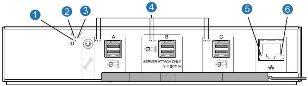
LED Description Definition
1 Identity Blue — The IOM is being identified.
2 Fault (Table 17) Off — The IOM is operating normally.
Amber — A fault has been detected or a service action is required.
3 OK (Table 17)
Green — The expansion module is operating normally. Blinking green — System is booting.
Off — The expansion module is powered off.
4 HD mini-SAS connector LEDs (A/B/C)
See Table 17 for SAS Port Activity (Green) LED states. See Table 18 on page 125 for Activity (Green) and Fault (Amber) LED states for additional information.
5 Ethernet Port Link/Active Status (Left)
Not used in this configuration.
6 Ethernet Port Link Speed (Right)
Not used in this configuration.
Table 17 provides the expansion IOM LED states.
Table 17 Expansion IOM LED States
| CRU OK(Green) | CRU Fault(Amber) | SAS PortActivity(Green) | Status |
| On Off - Expansion IOM OK | |||
| Off On - Expansion IOM fault: see Replacing a 2U RAID Controller or an Expansion IOM on page 177 | |||
| -- Off No external port connection | |||
| -- On HD mini-SAS port connection: no activity | |||
| -- Blinking HD mini-SAS port connection: activity | |||
| Blinking -- Expansion VPD error | |||
Table 18 provides companion data for Figure 103 relative to LED states for A/B/C SAS port expansion.
Table 18 IOM LED Activity States
| Condition Activity (Green) Fault (Amber) | ||
| No cable present Off Off | ||
| Cable present: all links up/no activity On Off | ||
| Cable present: all links up/with aggregate port activity Blinking | Off | |
| Critical fault: Any fault causing operation of the cable to cease or fail to start (e.g., over current trip). | Off On | |
| Non-critical fault: any fault that does not cause the connection to cease operation (e.g., not all links are established; over temperature). | Blinking Blinking: 1s on/1s off | |
5U Chassis LEDs
This section provides information about the 5U chassis PSU LEDs, fan LEDs, Ops panel LEDs, drawer LEDs, and DDIC LEDs.
NOTE: When the 5U84 chassis is powered on, all LEDs are lit for a short period to ensure they are working. This behavior does not indicate a fault unless LEDs remain lit after several seconds.
5U Chassis PSU LEDs
Under normal conditions, the PSU Power LEDs will be a constant green. Figure 104 provides an illustration of the 5U chassis PSU LEDs. The RAID chassis and the expansion chassis uses the same PSU. There are two PSUs in the RAID chassis and the expansion chassis.
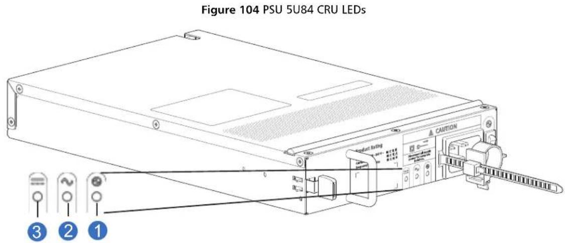
1 PSU OK LED: Green
2 AC Fail LED: Amber/blinking amber
3 PSU Fail LED: Amber/blinking amber
NOTE: If any of the PSU LEDs are illuminated amber, a module fault condition or failure has occurred.
When a fault occurs, the colors of the LEDs will display as shown in Table 19.
Table 195U Chassis PSU LEDs
| CRU Fail (Amber) | AC Missing (Amber) | Power (Green) | Status |
| On Off Off | No AC power | to either PSU. | |
| On On Off | PSU present, | but not sup | plying power or PSU alert state (usually due to critical temperature). |
| Off Off On | Main AC present, switch | on. This PSU is providing power. | |
| Off Off Blinking | AC power present, | PSU in standby (other PSU is providing power). | |
| Blinking Blinking | Off PSU firmware download in progress. | ||
| Off | On | Off | AC power missing, PSU in standby (other PSU is providing power). |
| On On On | Firmware has lost commu | unication with the PSU module. | |
| On | - | Off | PSU has failed. Follow procedure inReplacing a 5U84 System PSU on page 200. |
5U Chassis Fan Module LEDs
Figure 105 provides an illustration of the 5U chassis fan LEDs. The RAID chassis and the expansion chassis uses the same fans. There are five fans in the RAID chassis and the expansion chassis.
Figure 105 Fan 5U84 CRU LEDs
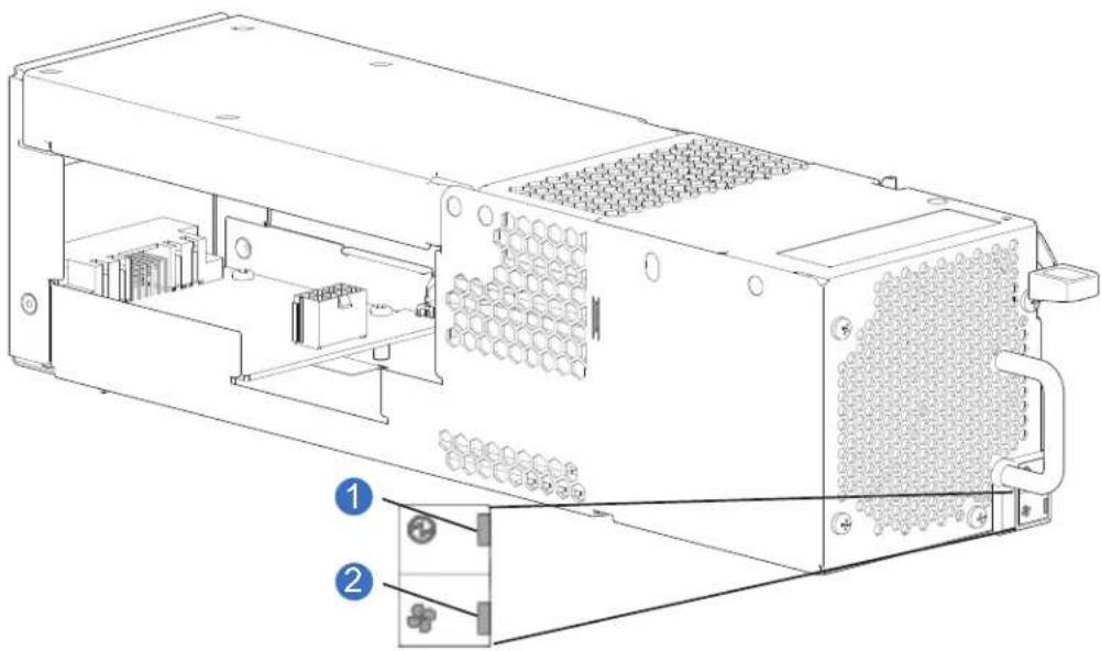
natural_image
Technical line drawing of an electronic device chassis with labeled components (no text or symbols present)1 Fan OK LED: Green
2 Fan Fail LED: Amber/blinking amber
Note: If any of the fan LEDs are illuminated amber, a module fault condition or failure has occurred.
Table 20 provides the fan LED status and description.
Table 205U Chassis Fan LEDs
| LED Status/Description | |
| Module OK | Constant green indicates that the fan is working correctly.Off indicates the fan module has failed. Follow procedure inReplacing a 5U84 System Fan on page 203. |
| Fan Fault | Amber indicates the fan module has failed. Follow procedure inReplacing a 5U84 System Fan on page 203. |
5U Chassis Ops Panel LEDs
The Ops panel displays the aggregated status of all the modules. Figure 106 provides an illustration of the 5U chassis Ops panel LEDs.
Figure 106 5U Chassis Ops Panel LEDs
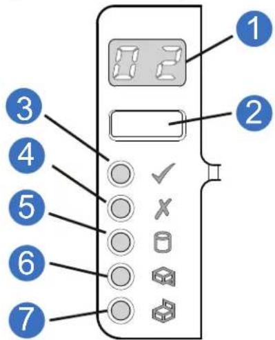
LED Status
1 Unit Identification Display Green: Seven segment display: chassis sequence
2 Input Switch Not used
3 System Power On/Standby Constant Green: positive indication
Constant Amber: system in standby (not operational)
4 Module Fault Constant or blinking amber: fault present
5 Logical Status Constant or blinking amber: fault present
6 Top Drawer Fault Constant or blinking amber: fault present in drive, cable, or sideplane.
7 Bottom Drawer Fault Constant or blinking amber: fault present in drive, cable, or sideplane.
Table 21 provides the Ops panel LED status and description.
Table 215U Chassis Ops Panel LEDs
| LED Status/Description | |
| Unit ID Display Usually shows the ID number for the chassis, but can be used for other purposes.(e.g., Blinking to locate chassis) | |
| Power On/Standby Amber if the system is in standby. Green if the system has full power. | |
| Module Fault Amber indicates a fault in a PSU, fan, RAID controller or expansion IOM.Check the drawer LEDs for indication of a disk fault.See also 5U Chassis Drawer LEDs on page 128. | |
| Logical Status | Amber indicates a fault from something other than firmware (usually a disk, an HBA,or an internal or external RAID controller).Check the drawer LEDs for indication of a disk fault.See also 5U Chassis Drawer LEDs on page 128. |
| Drawer 0 Fault Amber is a disk, cable, or sideplane fault in drawer 0.Open the drawer and check DDICs for faults. | |
| Drawer 1 Fault Amber is a disk, cable, or sideplane fault in drawer 1.Open the drawer and check DDICs for faults. | |
5U Chassis Drawer LEDs
Figure 107 provides an illustration of the 5U chassis drawer LEDs (left and right side of the drawer).
Figure 107 Drawer/Bezel LED Panel
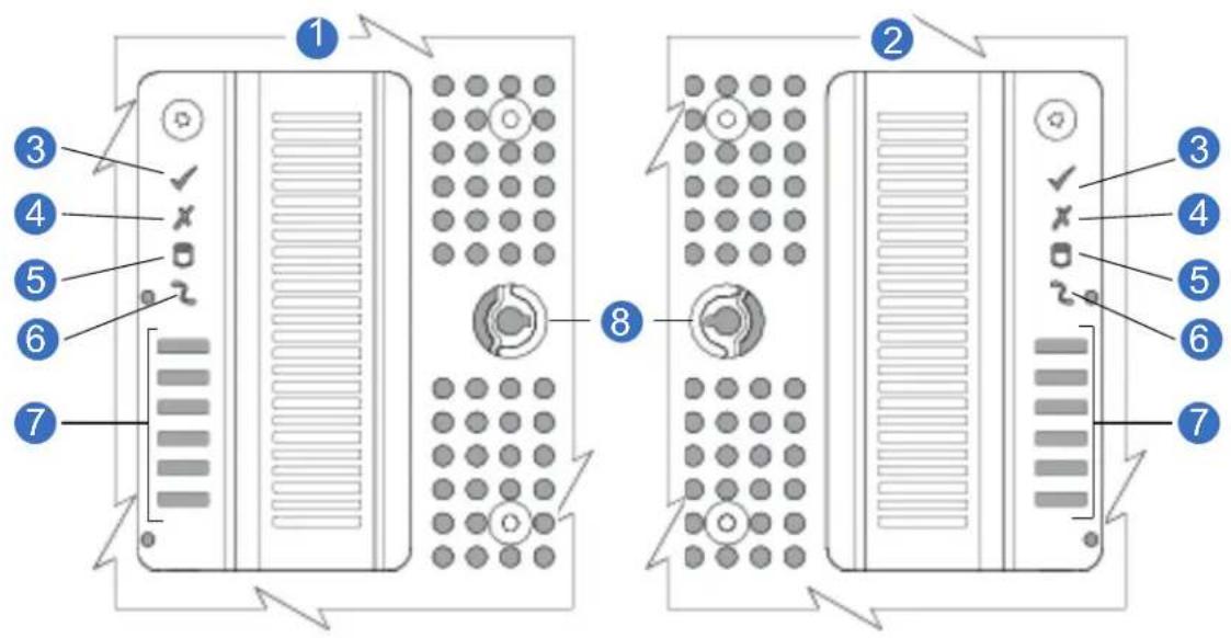
1 Left Side of Chassis 2 Right Side of Chassis 3 Sideplane OK/Power Good
4 Drawer Activity 5 Logical Fault 6 Cable Fault
7 Drawer Activity Indicators 8 Anti-tamper Lock Bar Graph
Table 22 provides the drawer LED status and description.
Table 225U Chassis Drawer LEDs
| LED Status/Description | |
| Sideplane OK/Power Good | Green if the sideplane card is working and there are no power problems. |
| Drawer Fault Amber | if a drawer component has failed.If the failed component is a disk, the LED on the failed DDIC will light amber.Follow procedure inReplacing a 5U84 DDIC on page 190.If the disks are OK, contact Quantum to identify the cause of the failure, and resolve the problem. |
| Logical Fault Amber | (solid) indicates a disk fault.Amber (blinking) indicates that one or more arrays are in an impacted state. |
| Cable Fault | Amber indicates the cabling between the drawer and the back of the chassis has failed. Contact Quantum to resolve the problem. |
| Activity Bar Graph | Displays the amount of data I/O from zero segments lit (no I/O) to all six segments lit (maximum I/O). |
5U Chassis DDIC LEDs
The DDIC supports LFF 3.5" and SFF 2.5" drives. Figure 108 shows the top panel of the DDIC as viewed when the drive is aligned for insertion into a drawer slot. See also Figure 57 on page 53.
Figure 108 DDIC LED
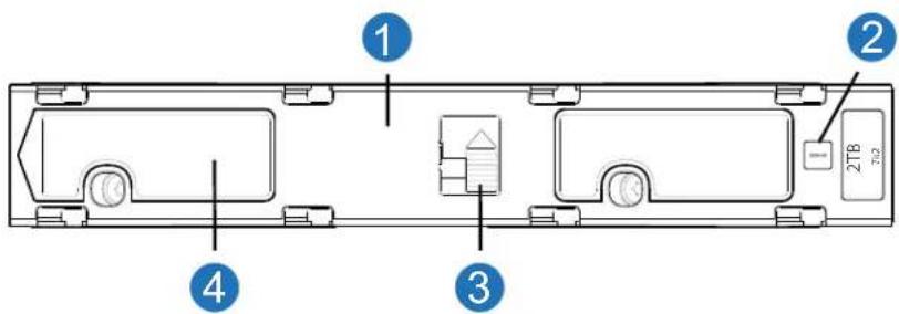
1 DDIC (longitudinal view - top face of carrier 2 Drive Fault LED
3 Latch Button (locked) 4 Slide Latch
Each DDIC has a single Drive Fault LED. A disk drive fault is indicated if the Drive Fault LED is lit amber. In the event of a drive failure, follow the procedure in Replacing a 5U84 DDIC on page 190. A blinking LED indicates disk locate.
5U RAID Controller LEDs
The 5U RAID controller is identical to the 2U RAID controller. Refer to QXS-412/424/484 12G Chassis RAID Chassis Controller LEDs on page 122 for the controller LEDs.
5U Expansion IOM LEDs
The 5U expansion IOM is identical to the 2U expansion IOM. Refer to 2U Chassis Expansion IOM LEDs on page 124 for the expansion IOM LEDs.
Temperature Sensors
Temperature sensors throughout the chassis and its components monitor the thermal health of the storage system. Exceeding the limits of critical values will cause a notification to occur.
Audible Alarm
The chassis includes an audible alarm, which indicates when a fault condition is present. The following conditions will activate the alarm:
- Fan fault or failure
• Voltage out of range
• Over or under temperature condition - Thermal overrun
- System fault
- Logical fault
- Power supply fault
- Removal of a PSU
Table 23 provides the audible alarm status.
Table 23 Audible Alarm Status
| Status Action with Mute Button Pressed | |||
| S0 Normal mode: silent Beep twice | |||
| S1 Fault mode: 1s on/1s off Transition to S2 or S3 (see table notes) | |||
| S2 Remind mode: intermittent beep None | |||
| S3 Muted mode: silent None | |||
| S4 Critical Fault mode: continuous alarm None: mute not active | |||
Table Notes
- During S1, if the mute button is not pressed after 2 minutes, the system automatically transitions to state S2 or S3.
- Alarm states S1 through S4 return to S0 state upon cessation of the fault.
• Critical Fault state S4 can be entered from any other state.
The audible alarm can be muted by pressing the mute button on the Ops panel. See 2U Chassis Ops Panel LEDs on page 117 and/or 5U Chassis Ops Panel LEDs on page 127. Automatic muting will occur after two minutes if the mute button is not manually operated. Once the alarm is muted, it will continue to sound with short intermittent beeps to indicate that a problem persists. The alarm will be silenced when all problems are resolved.
Troubleshooting 2U Chassis
The following sections describe common problems that can occur with your storage system, and some possible solutions. For all of the problems listed in Table 24, the Module Fault LED on the Ops panel will light amber to indicate a fault. See 2U Chassis Ops Panel LEDs on page 117. All alarms will also report via SES.
Table 242U Alarm Conditions
| Status Severity Alarm | ||
| PSU alert - loss of DC power from a single PSU | Fault - loss of redundancy S1 | |
| PSU fan fail Fault - loss of redundancy S1 | ||
| SBB module detected PSU fault Fault S1 | ||
| PSU removed Configuration error None | ||
| Chassis configuration error (VPD) | Fault – critical | S1 |
| Low warning temperature alert | Warning | S1 |
| High warning temperature alert | Warning | S1 |
| Over temperature alarm | Fault – critical | S4 |
| I^2C bus failure | Fault – loss of redundancy | S1 |
| Ops panel communication error ( I^2C ) | Fault – critical | S1 |
| RAID error | Fault – critical | S1 |
| SBB interface module fault | Fault – critical | S1 |
| SBB interface module removed | Warning | None |
| Drive power control fault | Warning – no loss of disk power | S1 |
| Drive power control fault | Fault – critical-loss of disk power | S1 |
| Drive removed | Warning | None |
| Insufficient power available | Warning | None |
For details about replacing modules, see 2U Chassis CRU Replacement on page 164.
NOTE: See the QXS 12G Event Descriptions Reference Guide for more information about chassis-related events and recommended actions.
PSU Faults
Table 25 provides PSU faults and the recommended actions.
Table 25 PSU Faults
| Symptom Cause Recommended Action | ||
| Ops panel Module Fault LED is amber ^2 | Any power fault | Verify AC mains connection to PSU are live |
| Fan Fail LED is illuminated on PSU ^2 | Fan failure Replace PSU | |
Thermal Monitoring and Control
The storage system uses extensive thermal monitoring and takes a number of actions to ensure component temperatures are kept low, and to also minimize acoustic noise. Air flow is from the front to back of the chassis.
Table 26 provides thermal faults and the recommended actions.
Table 26 Thermal Faults
| Symptom Cause Recommended | ed Action | |
| If the ambient air is below 25°C (77°F), and the fans are observed to increase in speed, then some restriction on airflow may be causing additional internal temperature rise.Note: This is not a fault condition. | The first stage in the thermal control process is for the fans to automatically increase in speed when a thermal threshold is reached.This may be caused by higher ambient temperatures in the local environment, and may be perfectly normal.Note: This threshold changes according to the number of drives and power supplies fitted. | 1 Check the installation for any airflow restrictions at either the front or back of the chassis. A minimum gap of 25 mm (1") at the front and 50 mm (2") at the rear is recommended.2 Check for restrictions due to dust build-up. Clean as appropriate.3 Check for excessive re-circulation of heated air from rear to front. Use of the chassis in a fully enclosed rack is not recommended.4 Verify that all blank modules are in place.5 Reduce the ambient temperature. |
Thermal Alarm
Table 27 provides thermal alarm faults and the recommended actions.
Table 27 Thermal Alarm Faults
| Symptom Cause Recommended | ed Action | |
| 1 Ops panel Module Fault LED is amber.2 Fan Fail LED is illuminated on one or more PSUs. | Internal temperature exceeds a preset threshold for the chassis. | 1 Verify that the local ambient environment temperature is within the acceptable range. See also QXS 2U/5U Environmental Requirements on page 215.2 Check the installation for any airflow restrictions at either the front or back of the chassis. A minimum gap of 25 mm (1") at the front and 50 mm (2") at the rear is recommended.3 Check for restrictions due to dust build-up. Clean as appropriate.4 Check for excessive re-circulation of heated air from rear to front. Use of the chassis in a fully enclosed rack is not recommended.5 If possible, shut down the chassis and investigate the problem before continuing. |
Troubleshooting 5U Chassis
Table 28 describes common problems that can occur with your storage system, together with possible solutions. For all of the problems listed in Table 28, the Module Fault LED on the Ops panel will light amber to indicate a fault. See 5U Chassis Ops Panel LEDs on page 127. All alarms will also report via SES.
For information about replacing modules, see 5U84 Chassis CRU Replacement on page 188.
Table 285U Alarm Conditions
| Status Severity | |
| PSU alert-loss of DC power from a single PSU Fault-loss of redundancy | |
| Cooling module fan failure Fault-loss of redundancy | |
| SBB I/O module detected PSU fault Fault | |
| PSU removed | Configuration error |
| Chassis configuration error (VPD) | Fault-critical |
| Low temperature warning | Warning |
| High temperature warning | Warning |
| Over-temperature alarm Fault-critical | |
| Under-temperature alarm | Fault-critical |
| I^2C bus failure | Fault-loss of redundancy |
Table 285U Alarm Conditions
| Status Severity | |
| Ops panel communication error ( I^2C ) | Fault-critical |
| RAID error Fault-critical | |
| SBB I/O module fault Fault-critical | |
| SBB I/O module removed Warning | |
| Drive power control fault Warning-no loss of drive power | |
| Drive power control fault Fault-critical: loss of drive power | |
| Insufficient power available Warning |
Thermal Considerations
Thermal sensors in the 5U chassis and its components monitor the thermal health of the storage system.
- Exceeding the limits of critical values will activate the over-temperature alarm.
• For information about 5U chassis alarm notification, see Table 28.
USB CLI Port Connection
The 2U and 5U controllers feature a CLI port employing a mini-USB Type B form factor. If you encounter problems communicating with the port after cabling your computer to the USB device, you may need to either download a device driver (Windows), or set appropriate parameters via an operating system command (Linux). See USB Device Connection on page 223 for more information.
Fault Isolation methodology
The 2U and 5U systems provide many ways to isolate faults. This section presents the basic methodology used to locate faults within a storage system, and to identify the pertinent CRUs affected.
As noted in Accessing Disk Management Utility (GUI) on page 112, use the disk management utility (GUI) to configure and provision the system upon completing the hardware installation.
- As part of this process, configure and enable event notification so the system will notify you when a problem occurs that is at or above the configured severity (see the Configuring event notification topic within the QXS 12G Disk Management Utility User Guide).
- With event notification configured and enabled, you can follow the recommended actions in the notification message to resolve the problem, as further discussed in the options presented below
Basic Steps
Follow these basic steps:
- Gather fault information, including using system LEDs as described in Gather Fault Information on page 136.
- Determine where in the system the fault is occurring as described in Determine Where the Fault is Occurring on page 136.
• Review event logs as described in Review the Event Logs on page 136. - If required, isolate the fault to a data path component or configuration as described in Isolate the Fault on page 137.
Cabling systems to enable use of the licensed replication feature—to replicate volumes—is another important fault isolation consideration pertaining to initial system installation. See Isolate the Fault on page 137 for more information about troubleshooting during initial setup.
Options Available for Performing Basic Steps
When performing fault isolation and troubleshooting steps, select the option or options that best suit your site environment. Use of any option (four options are described below) is not mutually exclusive to the use of another option. You can use the disk management utility (GUI) to check the health icons/values for the system and its components to ensure that everything is okay, or to drill down to a problem component. If you discover a problem, either the disk management utility (GUI) or the CLI provide recommended-action text online.
Options for performing basic steps are listed according to frequency of use:
- Use the disk management utility (GUI)
- Use the CLI
• Monitor event notification
• View the chassis LEDs
Use the Disk Management Utility (GUI)
The disk management utility (GUI) uses health icons to show OK, Degraded, Fault, or Unknown status for the system and its components. The disk management utility (GUI) enables you to monitor the health of the system and its components. If any component has a problem, the system health will be Degraded, Fault, or Unknown. Use the web application's GUI to drill down to find each component that has a problem, and follow actions in the Recommendation field for the component to resolve the problem.
Use the CLI
As an alternative to using the disk management utility (GUI), you can run the show system CLI command to view the health of the system and its components. If any component has a problem, the system health will be Degraded, Fault, or Unknown, and those components will be listed as Unhealthy Components. Follow the recommended actions in the component Health Recommendation field to resolve the problem.
Monitor Event Notification
With event notification configured and enabled, you can view event logs to monitor the health of the system and its components. If a message tells you to check whether an event has been logged, or to view information about an event in the log, you can do so using the disk management utility (GUI) or the CLI. Using the disk management utility (GUI), you would view the event log and then click on the event message to see detail about that event. Using the CLI, you would run the show events detail command (with additional parameters to filter the output) to see the detail for an event.
View the Chassis LEDs
You can view the LEDs on the hardware (while referring to LED descriptions for your chassis model) to identify component status. If a problem prevents access to the disk management utility (GUI) or the CLI, this is the only option available. However, monitoring/management is often done at a management console using storage management interfaces, rather than relying on line-of-sight to LEDs of racked hardware components.
Performing Basic Steps
You can use any of the available options described above in performing the basic steps comprising the fault isolation methodology.
Gather Fault Information
When a fault occurs, it is important to gather as much information as possible. Doing so will help you determine the correct action needed to remedy the fault.
Begin by reviewing the reported fault:
- Is the fault related to an internal data path or an external data path?
- Is the fault related to a hardware component such as a drive module, controller module, or power supply unit?
By isolating the fault to one of the components within the storage system, you will be able to determine the necessary corrective action more quickly.
Determine Where the Fault is Occurring
When a fault occurs, the Module Fault LED—located on the Ops panel on an chassis's left ear—illuminates. Check the LEDs on the back of the chassis to narrow the fault to a CRU, connection, or both. The LEDs also help you identify the location of a CRU reporting a fault. See one of the following:
• QXS-312 12G and QXS-324 12G RAID Chassis Rear View (2-Host Port Controllers) on page 16
- QXS-412 12G, QXS-424 12G, and QXS-484 12G RAID Chassis Rear View (4-Host Port Controllers) on page 18
• 2U12-Drive/2U24-Drive Expansion Chassis Rear View on page 19
• 5U84 RAID Chassis (Rear View/Two CNC Controllers) on page 24
• 5U84 Expansion Chassis (Rear View) on page 26
Use the disk management utility (GUI) to verify any faults found while viewing the LEDs. The disk management utility (GUI) is also a good tool to use in determining where the fault is occurring if the LEDs cannot be viewed due to the location of the system. This web-application provides you with a visual representation of the system and where the fault is occurring. The disk management utility (GUI) also provides more detailed information about CRUs, data, and faults.
Review the Event Logs
The event logs record all system events. Each event has a numeric code that identifies the type of event that occurred, and has one of the following severities:
- Critical. A failure occurred that may cause a controller to shut down. Correct the problem immediately.
-
Error. A failure occurred that may affect data integrity or system stability. Correct the problem as soon as possible.
-
Warning. A problem occurred that may affect system stability, but not data integrity. Evaluate the problem and correct it if necessary.
- Informational. A configuration or state change occurred, or a problem occurred that the system corrected. No immediate action is required.
NOTE: Some events also have a Resolved severity that indicates that a previously logged non-Informational condition has been resolved. See the Event Descriptions Reference Guide for information about specific events.
The event logs record all system events. It is very important to review the logs, not only to identify the fault, but also to search for events that might have caused the fault to occur. For example, a host could lose connectivity to a disk group if a user changes channel settings without taking the storage resources assigned to it into consideration. In addition, the type of fault can help you isolate the problem to either hardware or software.
Isolate the Fault
Occasionally, it might become necessary to isolate a fault. This is particularly true with data paths, due to the number of components comprising the data path. For example, if a host-side data error occurs, it could be caused by any of the components in the data path: controller module, cable, or data host.
If the Chassis Does Not Initialize
It may take up to two minutes for all chassis to initialize. If an chassis does not initialize:
- Perform a rescan
• Power cycle the system - Make sure the power cord is properly connected, and check the power source to which it is connected
- Check the event log for errors
Correcting Chassis IDs
When installing a system with drive chassis attached, the chassis IDs might not agree with the physical cabling order. This is because the controller might have been previously attached to chassis in a different configuration, and it attempts to preserve the previous chassis IDs, if possible. To correct this condition, make sure that both controllers are up, and perform a rescan using the disk management utility (GUI) or the CLI. This will reorder the chassis, but can take up to two minutes for the chassis IDs to be corrected.
To perform a rescan using the CLI, type the following command:
rescan
To perform a rescan using the disk management utility (GUI):
1 Verify that both controllers are operating normally.
2 Do one of the following:
a Point to the System tab and select Rescan Disk Channels.
b In the System topic. select Action > Rescan Disk Channels.
3 Click Rescan.
Host I/O
When troubleshooting drive and connectivity faults, stop I/O to the affected disk groups from all hosts as a data protection precaution. As an additional data protection precaution, it is helpful to conduct regularly scheduled backups of your data. See also Stopping I/O on page 179.
Dealing with Hardware Faults
Ensure that you have obtained a replacement module of the same type before removing any faulty module as described in Module Remove and Replace on page 163.
IMPORTANT: If the chassis system is powered up and you remove any module, replace it immediately.
If the system is used with any modules missing for more than a few seconds, the chassis can overheat, causing power failure and potential data loss. Such action can invalidate the product warranty.
IMPORTANT: Observe applicable/conventional ESD precautions when handling modules and components, as described in ESD Precautions on page 163.
Avoid contact with midplane components, module connectors, leads, pins, and exposed circuitry.
Isolating a Host-Side Connection Fault
During normal operation, when a controller module host port is connected to a data host, the port's host link status/link activity LED is green. If there is I/O activity, the host activity LED blinks green. If data hosts are having trouble accessing the storage system, and you cannot locate a specific fault or cannot access the event logs, use the following procedures. This procedure requires scheduled downtime.
IMPORTANT: Do not perform more than one step at a time. Changing more than one variable at a time can complicate the troubleshooting process.
Host-Side Connection Troubleshooting Featuring CNC Ports
The procedure below applies to controllers employing small form factor pluggable (SFP) transceiver connectors in 4/8/16Gb/s FC, 10GbE iSCSI, or 1Gb/s iSCSI host interface ports. In the following procedure, "SFP and host cable" is used to refer to any qualified SFP option supporting CNC ports used for I/O or replication.
NOTE: When experiencing difficulty diagnosing performance problems, consider swapping out one SFP at a time to see if performance improves.
1 Halt all I/O to the storage system. See also Stopping I/O on page 179.
2 Check the host link status/link activity LED.
If there is activity, halt all applications that access the storage system.
3 Check the Cache Status LED to verify that the controller cached data is flushed to the drives.
- Solid – Cache contains data yet to be written to the disk.
- Blinking – Cache data is being written to CompactFlash.
- Flashing at 1/10 second on and 9/10 second off – Cache is being refreshed by the super capacitor.
- Off – Cache is clean (no unwritten data).
4 Remove the SFP and host cable and inspect for damage.
5 Reseat the SFP and host cable.
Is the host link status/link activity LED on?
- Yes – Monitor the status to ensure that there is no intermittent error present. If the fault occurs again, clean the connections to ensure that a dirty connector is not interfering with the data path.
- No – Proceed to the next step.
6 Move the SFP and host cable to a port with a known good link status.
This step isolates the problem to the external data path (SFP, host cable and host-side devices) or to the controller module port.
Is the host link status/link activity LED on?
- Yes – You now know that the SFP, host cable, and host-side devices are functioning properly. Return the cable to the original port. If the link status LED remains off, you have isolated the fault to the controller module's port. Replace the controller module.
- No – Proceed to the next step.
7 Swap the SFP with the known good one.
Is the host link status/link activity LED on?
- Yes – You have isolated the fault to the SFP. Replace the SFP.
- No – Proceed to the next step.
8 Re-insert the original SFP and swap the cable with a known good one.
Is the host link status/link activity LED on?
- Yes – You have isolated the fault to the cable. Replace the cable.
- No – Proceed to the next step.
9 Verify that the switch, if any, is operating properly. If possible, test with another port.
10 Verify that the HBA is fully seated, and that the PCI slot is powered on and operational.
11 Replace the HBA with a known good HBA, or move the host side cable and SFP to a known good HBA.
Is the host link status/link activity LED on?
- Yes – You have isolated the fault to the HBA. Replace the HBA.
- No – It is likely that the controller module needs to be replaced.
12 Move the cable and SFP back to its original port.
Is the host link status/link activity LED on?
- No – The controller module port has failed. Replace the controller module.
- Yes – Monitor the connection for a period of time. It may be an intermittent problem, which can occur with damaged SFPs, cables, and HBAs.
Isolating a Controller Module Expansion Port Connection Fault
During normal operation, when a controller module's expansion port is connected to a expansion chassis, the expansion port status LED is green. If the connected port's expansion port LED is off, the link is down. Use the following procedure to isolate the fault. This procedure requires scheduled downtime.
NOTE: Do not perform more than one step at a time. Changing more than one variable at a time can complicate the troubleshooting process.
1 Halt all I/O to the storage system Stopping I/O on page 179.
2 Check the host activity LED.
If there is activity, halt all applications that access the storage system.
3 Check the Cache Status LED to verify that the controller cached data is flushed to the disk drives.
- Solid – Cache contains data yet to be written to the disk.
- Blinking – Cache data is being written to CompactFlash.
- Flashing at 1/10 second on and 9/10 second off – Cache is being refreshed by the supercapacitor.
- Off – Cache is clean (no unwritten data).
4 Reseat the expansion cable, and inspect it for damage.
Is the expansion port status LED on?
- Yes – Monitor the status to ensure there is no intermittent error present. If the fault occurs again, clean the connections to ensure that a dirty connector is not interfering with the data path.
- No – Proceed to the next step.
5 Move the expansion cable to a port on the controller with a known good link status.
This step isolates the problem to the expansion cable or to the controller module's expansion port.
Is the expansion port status LED on?
- Yes – You now know that the expansion cable is good. Return the cable to the original port. If the expansion port status LED remains off, you have isolated the fault to the controller module's expansion port. Replace the controller module.
- No – Proceed to the next step.
6 Move the expansion cable back to the original port on the controller.
7 Move the expansion cable on the expansion chassis to a known good expansion port on the expansion chassis.
Is the expansion port status LED on?
- Yes – You have isolated the problem to the expansion chassis port. Replace the expansion IOM.
- No – Proceed to the next step.
8 Replace the cable with a known good cable, ensuring the cable is attached to the original ports used by the previous cable.
Is the host link status LED on?
- Yes – Replace the original cable. The fault has been isolated.
- No – It is likely that the controller module must be replaced.
Isolating Replication Faults
Replication is a licensed disaster-recovery feature that performs asynchronous replication of block-level data from a volume in a primary storage system to a volume in a secondary system. The replication feature creates an internal snapshot of the primary volume, and copies changes to the data since the last replication to the secondary system via iSCSI or FC links.
The primary volume exists in a primary pool in the primary storage system. Replication can be completed using either the disk management utility (GUI) or the CLI. See Connecting Two 2U Storage Systems (4-Host Ports) for Replication on page 100 and Connecting Two 5U Storage Systems for Replication on page 101 for host connection information concerning the replication feature.
Replication Setup and Verification
After storage systems are cabled for replication, you can use the disk management utility (GUI) to prepare for using the replication feature. Alternatively, you can use SSH or telnet to access the IP address of the controller module and access the replication feature using the CLI.
Basic information for enabling the RAID chassis for replication supplements the troubleshooting procedures that follow.
- Familiarize yourself with replication content provided in the QXS 12G Disk Management Utility User Guide.
- For virtual replication, in order to replicate an existing volume to a pool on the peer in the primary system or secondary system, follow these steps:
• Find the port address on the secondary system:
Using the CLI, run the show ports command on the secondary system.
- Verify that ports on the secondary system can be reached from the primary system using either method below:
- Run the query peer-connection CLI command on the primary system, using a port address obtained from the output of the show ports command above.
- In the disk management utility (GUI) Replications topic, select Action > Query Peer Connection.
- Create a peer connection. To create a peer connection, use the create peer-connection CLI command or in the disk management utility (GUI) Replications topic, select Action > Create Peer Connection.
- Create a virtual replication set. To create a replication set, use the create replication-set CLI command or in the disk management utility (GUI) Replications topic, select Action > Create Replication Set.
- Replicate.
- To initiate replication, use the replicate CLI command or in the disk management utility (GUI) Replications topic, select Action > Replicate.
- For descriptions of replication-related events, see the Event Descriptions Reference Guide.
NOTE: These steps are a general outline of the replication setup. Refer to the following manuals for more information about replication setup:
• See the QXS 12G Disk Management Utility User Guide for procedures to setup and manage replications.
• See the QXS 12G CLI Reference Guide for replication commands and syntax.
• See the QXS 12G Disk Management Utility User Guide and the QXS12G Event Descriptions Reference Guide for replication event reporting.
IMPORTANT: Controller module firmware must be compatible on all systems used for replication. For license information, see the disk management utility (GUI).
Diagnostic Steps for Replication Setup
The tables in this subsection show menu navigation for virtual replication using the disk management utility (GUI).
Using the Replication Feature
Can you successfully use the replication feature?
Table 29 Diagnostics for Replication Setup: Using the Replication Feature
| Answer Possible reasons Action | |
| Yes System functioning properly. No action required. | |
| No The replication feature is not licensed on each RAID chassis used for replication. | Verify licensing of the optional feature per system:In theHometopic in the disk management utility (GUI), selectAction > Install License.The License Settings panel opens and displays information about each licensed feature.If the replication feature is not enabled, obtain and install a valid license for this feature.See theQXS 12G Disk Management Utility User Guidefor license information. |
| No Compatible firmware revision supporting the replication feature is not running on each system used for replication. | Perform the following actions on each system used for virtual replication:In theSystemtopic, selectAction > Update Firmware.The Update Firmware panel opens. The Update Controller Modules tab shows firmware versions installed in each controller.If necessary, update the controller module firmware to ensure compatibility with the other systems.For more information on compatible firmware, see the topic about updating firmware in theQXS 12G Disk Management Utility User Guide. |
Table 29 Diagnostics for Replication Setup: Using the Replication Feature (continued)
| Answer Possible reasons Action | ||
| No Invalid | cabling connection.(If multiple chassis are used, check the cabling for each system.) | Verify controller on RAID chassis cabling:· Verify use of proper cables.· Verify proper cabling paths for host connections.· Verify cabling paths between replication ports and switches are visible to one another.· Verify that cable connections are securely fastened.· Inspect cables for damage and replace if necessary. |
| No A system | does not have a pool configured. | Configure each system to have a storage pool. |
Creating a Replication Set
Can you create a replication set?
Table 30 Diagnostics for Replication setup: Creating a Replication Set
| Answer Possible reasons Action | |
| Yes System functioning properly. No action required. | |
| No On RAID chassis equipped with iSCSI host interface ports, replication set creation fails due to use of CHAP. | If using CHAP (Challenge-Handshake Authentication Protocol), see the topics about configuring CHAP and working in replications within the QXS 12G Disk Management Utility User Guide. |
| No Unable to create the secondary volume (the destination volume on the pool to which you will replicate data from the primary volume)? ^1 | Review event logs (in the footer, click the events panel and select Show Event List) for indicators of a specific fault in a replication data path component. Follow any Recommended Actions.Verify valid specification of the secondary volume according to either of the following criteria:A conflicting volume does not already existAvailable free space in the pool |
| No Communication link is down. Review event logs for indicators of a specific fault in a host or replication data path component. | |
^1 After ensuring valid licensing, valid cabling, and network availability, create the replication set using the Replications topic: select Action > Create Replication Set.
Replicating a Volume
Can you replicate a volume?
Table 31 Diagnostics for Replication Setup: Replicating a Volume
| Answer Possible reasons Action | ||
| Yes System functioning properly. No action required. | ||
| No The replication feature is not licensed on each RAID chassis used for replication. | See actions described in Using the Replication Feature on page 142. | |
| No | Nonexistent replication set. | ·Determine existence of primary or secondary volumes.·If a replication set has not been successfully created, use the Replications topic: select Action > Create Replication Set to create one.·Review event logs (in the footer, click the events panel and select Show Event List) for indicators of a specific fault in a replication data path component. Follow any Recommended Actions. |
| No Network error occurred during in-progress replication. | ·Review event logs for indicators of a specific fault in a replication data path component. Follow any Recommended Actions.·Click in the Volumes topic, then click on a volume name in the volumes list. Click the Replication Sets tab to display replications and associated metadata.·Replications that enter the suspended state can be resumed manually (see the QXS 12G Disk Management Utility User Guide for additional information). | |
| No Communication link is down. Review event logs for indicators of a specific fault in a host or replication data path component. | ||
Checking for a Successful Replication
Table 32 Diagnostics for Replication Setup: Checking for a Successful Replication
| Answer | Possible reasons Action | |
| Yes | System functioning properly. No action required. | |
| No | Last Successful Run shows N/A. | In the Volumes topic, click on the volume that is a member of the replication set.Select the Replication Sets table.Check the Last Successful Run information.If the replication has not run successfully, use the disk management utility (GUI) to replicate as described in the topic about working in replications in the QXS 12G Disk Management Utility User Guide |
| No | Communication link is down. Review event logs for indicators of a specific fault in a host or replication data path component. | |
Continuous Operation During Replacement
Your hardware or software chassis management application determines the capability for replacing a failed drive without the loss of access to any file system on the chassis. Chassis access and use during this period is uninterrupted. If a chassis is equipped with redundant PSUs, sufficient power is provided to the system while the faulty module is replaced.
The QXS-312 12G, QXS-324 12G, QXS-412 12G, QXS-424 12G, and QXS-484 12G systems support hot-plug replacement of redundant controller modules, power supplies, and expansion modules. Hot-add replacement of expansion chassis is also supported.
Firmware Updates
After installing the hardware and powering on the storage system components for the first time, verify that the controller modules, expansion modules, and drives are using the current firmware release. Periodically, you should ensure that the firmware versions used in expansion IOMs are compatible. Also see Updating Firmware on page 84.
Customer-Replaceable Units
This section provides the following information:
• 2U 2-/4-Port Controller RAID Chassis Matrix
• 5U 4-Port Controller RAID Chassis Matrix
• 2U12 RAID Chassis/Expansion Chassis CRUs
• 2U24 RAID Chassis/Expansion Chassis CRUs
• 5U84 RAID Chassis/Expansion Chassis CRUs
• RAID Controllers and Expansion IOMs for QXS 12G Systems
2U 2-/4-Port Controller RAID Chassis Matrix
Table 33 provides the type of host attach for the 2U12 and 2U24 controllers in the RAID chassis.
Table 332U 2-/4-Port Controller RAID Chassis Matrix
| 3.5" (LFF) 12-Drive RAID Chassis 2.5" (SFF) 24-Drive | RAID Chassis | ||||
| QXS-31212G & QXS-41212G System | Description Form QXS-324 | 12G & Channel QXS-42412G System | Description Form | ||
| Fibre Channel (8/16Gb/s) SFP^1,4 | 2U12 Fibre | 8/16Gb/s) SFP^1,4 | 2U24 | ||
| Internet SCSI (10GbE) SFP^2,4 | 2U12 | Internet SCSI (10GbE) SFP^2,4 | 2U24 | ||
| Internet SCSI (1Gb/s) SFP^3,4 | 2U12 | Internet SCSI (1Gb/s) SFP^3,4 | 2U24 | ||
Table33 Notes
• ^1 This model uses a qualified FC SFP option within the CNC ports (used for host connection).
- When in FC mode, the SFPs must be a qualified 8Gb or 16Gb fiber-optic option.
- A 16Gb/s SFP can run at 16Gb/s, 8Gb/s, 4Gb/s, or auto-negotiate its link speed.
- An 8Gb/s SFP can run at 8Gb/s, 4Gb/s, or auto-negotiate its link speed.
- ^2 This model uses a qualified 10GbE iSCSI option within the controller module CNC ports (used for host connection).
- ^3 This model uses a qualified 1Gb iSCSI SFP option within the controller module CNC ports (used for host connection).
- ^4 CNC ports support same-type or mixed-type SFPs in combination as described in RAID Controller and Expansion IOMs on page 39.
5U 4-Port Controller RAID Chassis Matrix
Table 34 provides the type of host attach for the 5U84 controllers in the RAID chassis.
Table 345U 4-Port Controller RAID Chassis Matrix
| 2.5" (SFF)/3.5" (LFF) 84-Drive RAID Chassis | ||
| QXS-484 12G System | Description Form | |
| Fibre Channel (8/16Gb/s) SFP ^1,4 | 5U84 | |
| Internet SCSI (10GbE) SFP ^2,4 | 5U84 | |
| Internet SCSI (1Gb/s) SFP ^3,4 | 5U84 | |
Table34 Notes
• ^1 This model uses a qualified FC SFP option within the CNC ports (used for host connection).
- When in FC mode, the SFPs must be a qualified 8Gb or 16Gb fiber-optic option.
- A 16Gb/s SFP can run at 16Gb/s, 8Gb/s, 4Gb/s, or auto-negotiate its link speed.
- An 8Gb/s SFP can run at 8Gb/s, 4Gb/s, or auto-negotiate its link speed.
- ^2 This model uses a qualified 10GbE iSCSI option within the controller module CNC ports (used for host connection).
- ^3 This model uses a qualified 1Gb iSCSI SFP option within the controller module CNC ports (used for host connection).
- ^4 CNC ports support same-type or mixed-type SFPs in combination as described in RAID Controller and Expansion IOMs on page 39.
2U12 RAID Chassis/Expansion Chassis CRUs
This section provides the following information:
• 2U12 RAID Chassis CRUS (Front)
• 2U12 QXS-312 12G RAID Chassis CRUS (Rear)
• 2U12 QXS-412 12G RAID Chassis CRUS (Rear)
• 2U12 Expansion Chassis CRUs (Front)
• 2U12 Expansion Chassis CRUs (Rear)
2U12 RAID Chassis CRUS (Front)
Figure 109 provides the location of the 2U12 RAID chassis CRUs (front). The QXS-312 12G and QXS-412 12G both look the same in front.
Figure 109 2U12 RAID Chassis CRUS (Front)
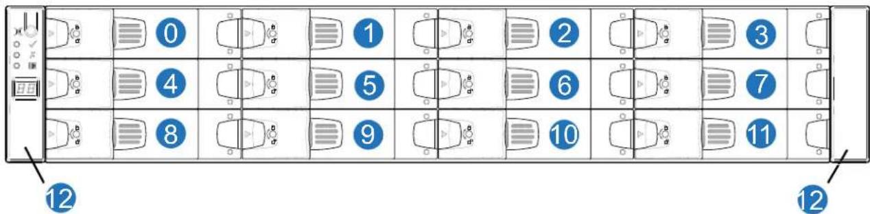
Table 35 provides a list of CRUs in the 2U12 RAID chassis (front and additional CRUs not shown).
Table 352U12 RAID Chassis CRUs (Front)
| Item Chassis Component Description | |
| 0-11 Drives (SFF or LFF) | |
| Dummy drive carrier module (blank to maintain optimum air flow within chassis) | |
| 12 Ear components | |
| Note: The 2U12 RAID Chassis bezel is a CRU (not shown) and can be replaced.SeeRemoving a 2U Bezel on page 165 andInstalling a 2U Bezel on page 165 for the 2U12 bezel replacement. | |
| Additional CRUs Not Shown | |
| Chassis Chassis (sheet metal chassis that is configurable as a RAID or expansion chassis) | |
| Rail Kit Rail kit (variable attachment options)2U rack mount kit, shelf, short, all HW |
Table 352U12 RAID Chassis CRUs (Front)
| Item Chassis Component Description | |
| Cable Kits | Cable kit [Cable package: standard HD mini-SAS (SFF-8644) to HD mini-SAS (SFF-8644)] |
| Cable kit [Cable package: standard HD mini-SAS (SFF-8644) to mini-SAS (SFF-8088)] | |
| Cable kit [Cable package: USB Type B; CLI (USB)] | |
| Power Cord | AC power cord compatible with AC PSU(s) |
2U12 QXS-312 12G RAID Chassis CRUS (Rear)
Figure 110 provides the location of the 2U12 RAID chassis CRUs (rear) with two CNC controllers installed (2-host ports).
NOTE: Depending on customer requirements, the controllers can be CNC (FC or iSCSI) for host connection (2-host port connections per controller).
Figure 110 2U12 RAID Chassis CRUS (Rear) with Two CNC Controllers (2-Host Ports)
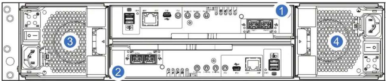
Table 37 provides a list of CRUs in the 2U12 RAID chassis (rear) for Figure 111.
Table 362U12 RAID Chassis CRUs (Rear)
| Item Chassis Component Description | |
| 1 Controller AThe host interfaces for storage systemThe 2-port FC/iSCSI supports (8/16Gb/s FC; 10GbE iSCSI; or 1Gb/s iSCSI) qualified SFP options* | |
| 2 Controller BThe host interfaces for storage systemThe 2-port FC/iSCSI supports (8/16Gb/s FC; 10GbE iSCSI; or 1Gb/s iSCSI) qualified SFP options* | |
| 3 PSU0 | |
| 4 PSU1 | |
| 5 | Small form-pluggable (SFP) connectors for CNC controllers:2 each per controller*SFP transceiver: 8/16Gb/s FC; 10GbE iSCSI; 1Gb/s iSCSI |
| *QXS-312 12G RAID chassis support FC and iSCSI SFPs used in combination. | |
NOTE: Figure 101 on page 120 provides a representative example of the controllers used in the RAID chassis.
Figure 125 on page 162 provides a representative example of the IOMs used in the expansion chassis.
The QXS-312 12G and QXS-324 12G systems use the same identical controllers and IOMs.
2U12 QXS-412 12G RAID Chassis CRUS (Rear)
Figure 111 provides the location of the 2U12 RAID chassis CRUs (rear) with two CNC controllers installed (4-host port connections per controller).
NOTE: Depending on customer requirements, the controllers can be CNC (FC or iSCSI) for host connection (4-host port connections per controller)
Figure 111 2U12 RAID Chassis CRUS (Rear) with Two CNC Controllers (4-Host Ports)
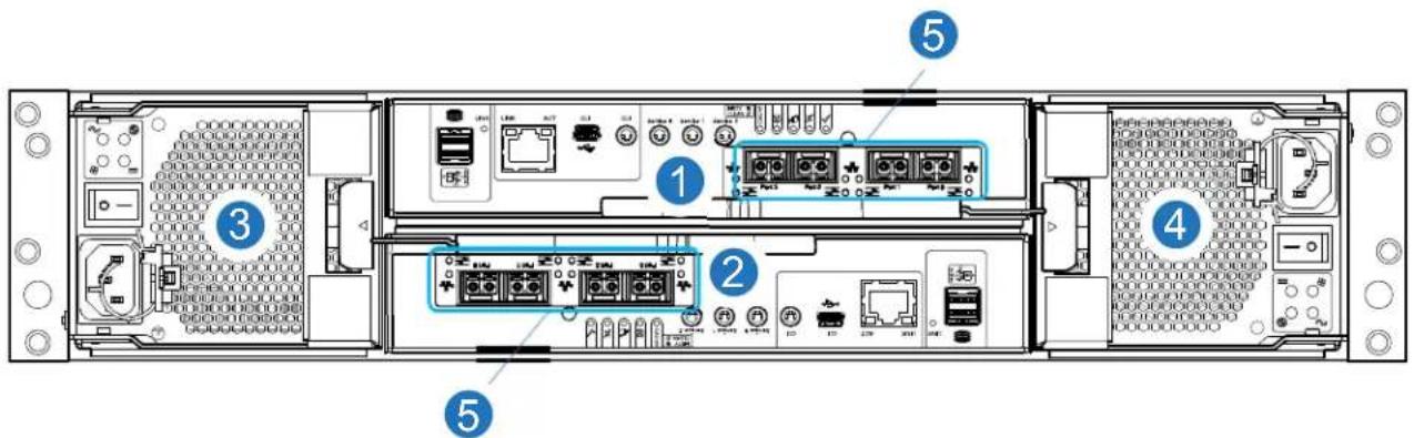
Table 37 provides a list of CRUs in the 2U12 RAID chassis (rear) for Figure 111.
Table 372U12 RAID Chassis CRUs (Rear)
| Item Chassis Component Description | |
| 1 Controller AThe host interfaces for storage systemThe 4-port FC/iSCSI supports (8/16Gb/s FC; 10GbE iSCSI; or 1Gb/s iSCSI) qualified SFP options* | |
| 2 Controller BThe host interfaces for storage systemThe 4-port FC/iSCSI supports (8/16Gb/s FC; 10GbE iSCSI; or 1Gb/s iSCSI) qualified SFP options* | |
| 3 PSU0 | |
| 4 PSU1 | |
Table 372U12 RAID Chassis CRUs (Rear)
| Item Chassis Component Description | |
| 5 | Small form-pluggable (SFP) connectors for CNC controllers:4 each per controller*SFP transceiver: 8/16Gb/s FC; 10GbE iSCSI; 1Gb/s iSCSI |
| *QXS-412 12G RAID chassis support FC and iCSI SFPs used in combination. | |
NOTE: Figure 124 on page 161 provides a representative example of the controllers used in the RAID chassis.
Figure 125 on page 162 provides a representative example of the IOMs used in the expansion chassis.
The QXS-412 12G, QXS-424 12G, and QXS-484 12G systems use the same identical controllers and IOMs.
2U12 Expansion Chassis CRUs (Front)
Figure 112 provides the location of the 2U12 expansion chassis CRUs (front). The 2U12 expansion chassis is used with the QXS-312 12G and QXS-412 12G systems.
Figure 112 2U12 Expansion Chassis CRUS (Front)
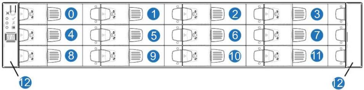
Table 38 provides a list of CRUs in the 2U12 expansion chassis (front and additional CRUs not shown).
Table 382U12 RAID Chassis CRUs (Front)
| Item Chassis Component Description | |
| 0-11 Drives (SFF or LFF) | |
| 12 Ear components | |
| Note: The 2U12 Expansion Chassis bezel is a CRU (not shown) and can be replaced.SeeRemoving a 2U Bezel on page 165 andInstalling a 2U Bezel on page 165 for the 2U12 bezel replacement. |
Table 382U12 RAID Chassis CRUs (Front)
| Item Chassis Component Description | |
| Additional CRUs Not Shown | |
| Chassis Chassis (sheet metal chassis that is configurable as a RAID or expansion chassis) | |
| Rail Kit Rail kit (variable attachment options)2U rack mount kit, shelf, short, all HW | |
| Cable Kits | Cable kit [Cable package: standard HD mini-SAS (SFF-8644) to HD mini-SAS (SFF-8644)] |
| Cable kit [Cable package: standard HD mini-SAS (SFF-8644) to mini-SAS (SFF-8088)] | |
| Cable kit [Cable package: USB Type B; CLI (USB)] | |
| Power Cord | AC power cord compatible with AC PSU(s) |
2U12 Expansion Chassis CRUs (Rear)
Figure 113 provides the location of the 2U12 expansion chassis CRUs (rear) with two expansion IOMs installed.
Figure 113 2U12 Expansion Chassis CRUS (Rear) with Two Expansion IOMs
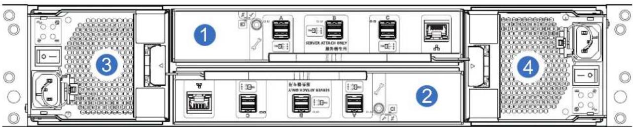
Table 39 provides a list of CRUs in the 2U12 expansion chassis (rear) for Figure 113.
Table 392U12 Expansion Chassis CRUs (Rear)
| Item Chassis Component Description | |
| 1 Expansion IOM A | |
| 2 Expansion IOM B | |
| 3 PSU0 | |
| 4 PSU1 | |
NOTE: Figure 124 on page 161 provides a representative example of the controllers used in the RAID chassis.
Figure 125 on page 162 provides a representative example of the IOMs used in the expansion chassis.
The QXS-312 12G, QXS-324 12G, QXS-412 12G, QXS-424 12G, and QXS-484 12G use the same identical IOMs.
2U24 RAID Chassis/Expansion Chassis CRUs
This section provides the following information:
• 2U24 RAID Chassis CRUS (Front)
• 2U24 QXS-324 12G RAID Chassis CRUS (Rear)
• 2U24 QXS-424 12G RAID Chassis CRUS (Rear)
• 2U24 Expansion Chassis CRUs (Front)
• 2U24 Expansion Chassis CRUs (Rear)
2U24 RAID Chassis CRUS (Front)
Figure 114 provides the location of the 2U24 RAID chassis CRUs (front). The QXS-324 12G and QXS-424 12G both look the same in front.
Figure 114 2U24 RAID Chassis CRUS (Front)
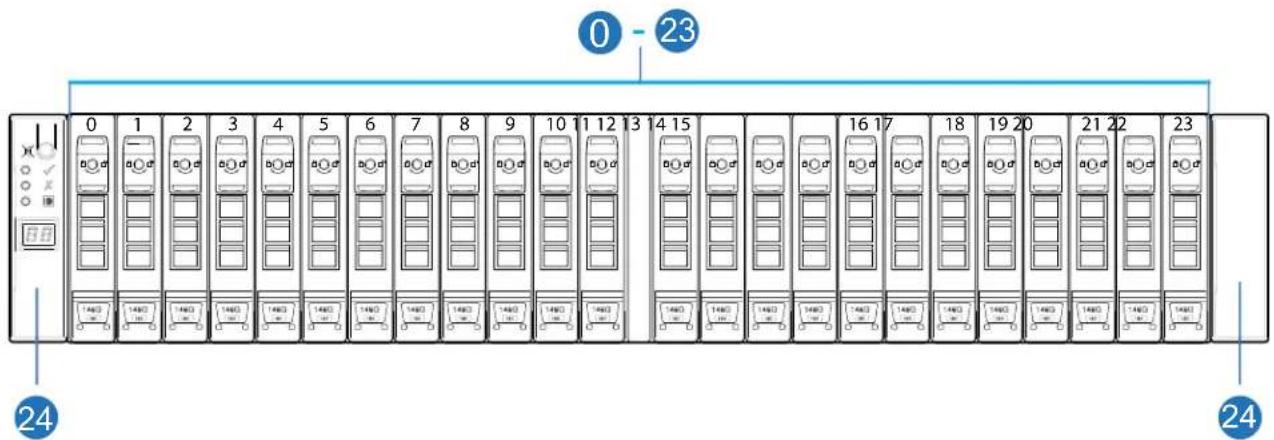
Table 40 provides a list of CRUs in the 2U24 RAID chassis (front and additional CRUs not shown).
Table 402U24 RAID Chassis CRUs (Front)
| Item Chassis Component Description | |
| 0-23 Drives | |
| 24 Ear components | |
| Note: The 2U24 RAID Chassis bezel is a CRU (not shown) and can be replaced.SeeRemoving a 2U Bezel on page 165 andInstalling a 2U Bezel on page 165 for the 2U24 bezel replacement. | |
| Additional CRUs Not Shown | |
| Chassis Chassis (sheet metal chassis that is configurable as a RAID or expansion chassis) | |
| Rail Kit Rail kit (variable attachment options)2U rack mount kit, shelf, short, all HW |
Table 402U24 RAID Chassis CRUs (Front)
| Item Chassis Component Description | |
| Cable Kits | Cable kit [Cable package: standard HD mini-SAS (SFF-8644) to HD mini-SAS (SFF-8644)] |
| Cable kit [Cable package: standard HD mini-SAS (SFF-8644) to mini-SAS (SFF-8088)] | |
| Cable kit [Cable package: USB Type B; CLI (USB)] | |
| Power Cord | AC power cord compatible with AC PSU(s) |
2U24 QXS-324 12G RAID Chassis CRUS (Rear)
Figure 115 provides the location of the 2U24 RAID chassis CRUs (rear) with two CNC controllers installed (2-host ports).
NOTE: Depending on customer requirements, the controllers can be CNC (FC or iSCSI) for host connection (2-host ports per controller).
Figure 115 2U24 RAID Chassis CRUS (Rear) with Two CNC Controllers (2-Host Ports)
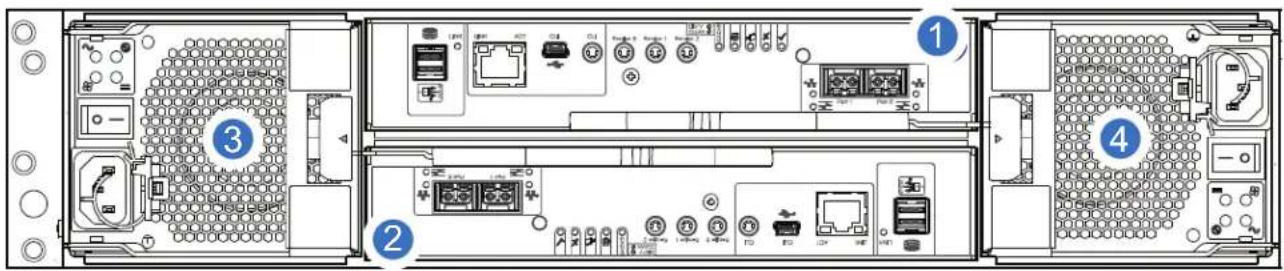
Table 41 provides a list of CRUs in the 2U24 RAID chassis (rear) for Figure 115.
Table 41 2U24 RAID Chassis CRUs (Rear)
| Item Chassis Component Description | |
| 1 Controller AThe host interfaces for storage system.The 2-port FC/iSCSI supports (8/16Gb/s FC; 10GbE iSCSI; or 1Gb/s iSCSI) qualified SFP options*. | |
| 2 Controller BThe host interfaces for storage system.The 2-port FC/iSCSI supports (8/16Gb/s FC; 10GbE iSCSI; or 1Gb/s iSCSI) qualified SFP options*. | |
| 3 PSU0 | |
| 4 PSU1 | |
| 5 | Small form-pluggable (SFP) connectors for CNC controllers:2 each per controller*SFP transceiver: 8/16Gb/s FC; 10GbE iSCSI; 1Gb/s iSCSI |
*QXS-324 12G RAID chassis support FC and iSCSI SFPs used in combination.
NOTE: Figure 123 on page 161 provides a representative example of the controllers used in the RAID chassis.
Figure 125 on page 162 provides a representative example of the IOMs used in the expansion chassis.
The QXS-312 12G, QXS-324 12G, QXS-412 12G, QXS-424 12G, and QXS-484 12G use the same identical IOMs.
2U24 QXS-424 12G RAID Chassis CRUS (Rear)
Figure 116 provides the location of the 2U24 RAID chassis CRUs (rear) with two CNC controllers installed (4-host ports).
NOTE: Depending on customer requirements, the controllers can be CNC (FC or iSCSI) for host connection (4-host ports per controller).
Figure 116 2U24 RAID Chassis CRUS (Rear) with Two CNC Controllers (4-Host Ports)
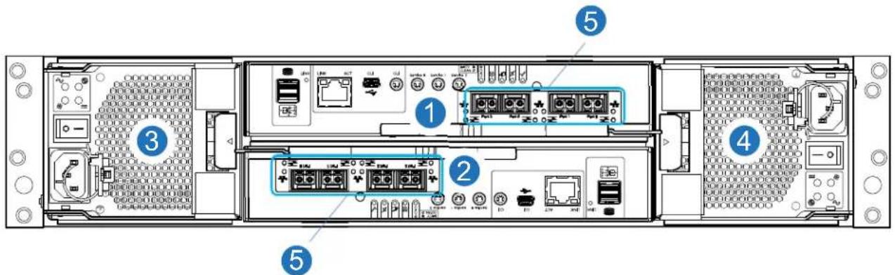
Table 42 provides a list of CRUs in the 2U24 RAID chassis (rear) for Figure 116.
Table 42 2U24 RAID Chassis CRUs (Rear)
| Item Chassis Component Description | |
| 1 Controller AThe host interfaces for storage system.The 4-port FC/iSCSI supports (8/16Gb/s FC; 10GbE iSCSI; or 1Gb/s iSCSI) qualified SFP options*. | |
| 2 Controller BThe host interfaces for storage system.The 4-port FC/iSCSI supports (8/16Gb/s FC; 10GbE iSCSI; or 1Gb/s iSCSI) qualified SFP options*. | |
| 3 PSU0 | |
| 4 PSU1 | |
Table 42 2U24 RAID Chassis CRUs (Rear)
| Item Chassis Component Description | |
| 5 | Small form-pluggable (SFP) connectors for CNC controllers:4 each per controller*SFP transceiver: 8/16Gb/s FC; 10GbE iSCSI; 1Gb/s iSCSI |
| *QXS-424 12G RAID chassis support FC and iSCSI SFPs used in combination. | |
NOTE: Figure 124 on page 161 provides a representative example of the controllers used in the RAID chassis.
Figure 125 on page 162 provides a representative example of the IOMs used in the expansion chassis.
The QXS-312 12G, QXS-324 12G, QXS-412 12G, QXS-424 12G, and QXS-484 12G use the same identical IOMs.
2U24 Expansion Chassis CRUs (Front)
Figure 117 provides the location of the 2U24 expansion chassis CRUs (front).
Figure 117 2U24 Expansion Chassis CRUS (Front)
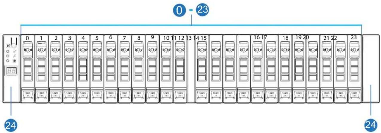
Table 43 provides a list of CRUs in the 2U24 expansion chassis (front and additional CRUs not shown).
Table 432U24 RAID Chassis CRUs (Front)
| Item Chassis Component Description | |
| 0-23 Drives | |
| 0-23 Drives (SFF) | |
| 24 | Ear components |
| Left ear assembly | |
| Right ear assembly | |
Table 432U24 RAID Chassis CRUs (Front)
| Item Chassis Component Description | |
| Note: The 2U24 Expansion Chassis bezel is a CRU (not shown) and can be replaced.SeeRemoving a 2U Bezel on page 165 andInstalling a 2U Bezel on page 165 for the 2U24 bezel replacement. | |
| Additional CRUs Not Shown | |
| Chassis Chassis (sheet metal chassis that is configurable as a RAID or expansion chassis) | |
| Rail Kit Rail kit (variable attachment options)2U rack mount kit, shelf, short, all HW | |
| Cable Kits | Cable kit [Cable package: standard HD mini-SAS (SFF-8644) to HD mini-SAS (SFF-8644)] |
| Cable kit [Cable package: standard HD mini-SAS (SFF-8644) to mini-SAS (SFF-8088)] | |
| Cable kit [Cable package: USB Type B; CLI (USB)] | |
| Power Cord | AC power cord compatible with AC PSU(s) |
2U24 Expansion Chassis CRUs (Rear)
Figure 113 provides the location of the 2U24 expansion chassis CRUs (rear) with two expansion IOMs installed.
Figure 118 2U24 Expansion Chassis CRUS (Rear) with Two Expansion IOMs
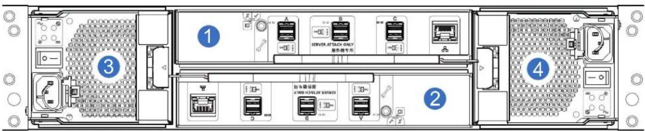
Table 44 provides a list of CRUs in the 2U24 expansion chassis (rear) for Figure 118.
Table 442U24 Expansion Chassis CRUs (Rear)
| Item Chassis Component Description | |
| 1 Expansion IOM A | |
| 2 Expansion IOM B | |
| 3 PSU0 | |
| 4 PSU1 | |
NOTE: Figure 124 on page 161 provides a representative example of the controllers used in the RAID chassis.
Figure 125 on page 162 provides a representative example of the IOMs used in the expansion chassis.
The QXS-312 12G, QXS-324 12G, QXS-412 12G, QXS-424 12G, and QXS-484 12G use the same identical IOMs.
5U84 RAID Chassis/Expansion Chassis CRUs
This section provides the following information:
• 5U84 RAID Chassis/Expansion Chassis (Front View)
• 5U84 RAID Chassis/Expansion Chassis Drawer (Drives/CRUs)
• 5U84 RAID Chassis CRUs (Rear View/Two CNC Controllers)
• 5U84 Expansion Chassis CRUs (Rear View)
5U84 RAID Chassis/Expansion Chassis (Front View)
Figure 119 provides an illustration of the front of the 5U84 RAID or expansion chassis (with bezel installed). Drawer 0 is at the top of the chassis. Drawer 1 is at the bottom of the chassis.
NOTE: The bezel for drawer 0 and drawer 1 are CRUs and can be replaced if required. See Replacing a 5U84 Bezel on page 194 for the 5U84 bezel replacement.
Figure 119 Front of 5U84 RAID or Expansion Chassis
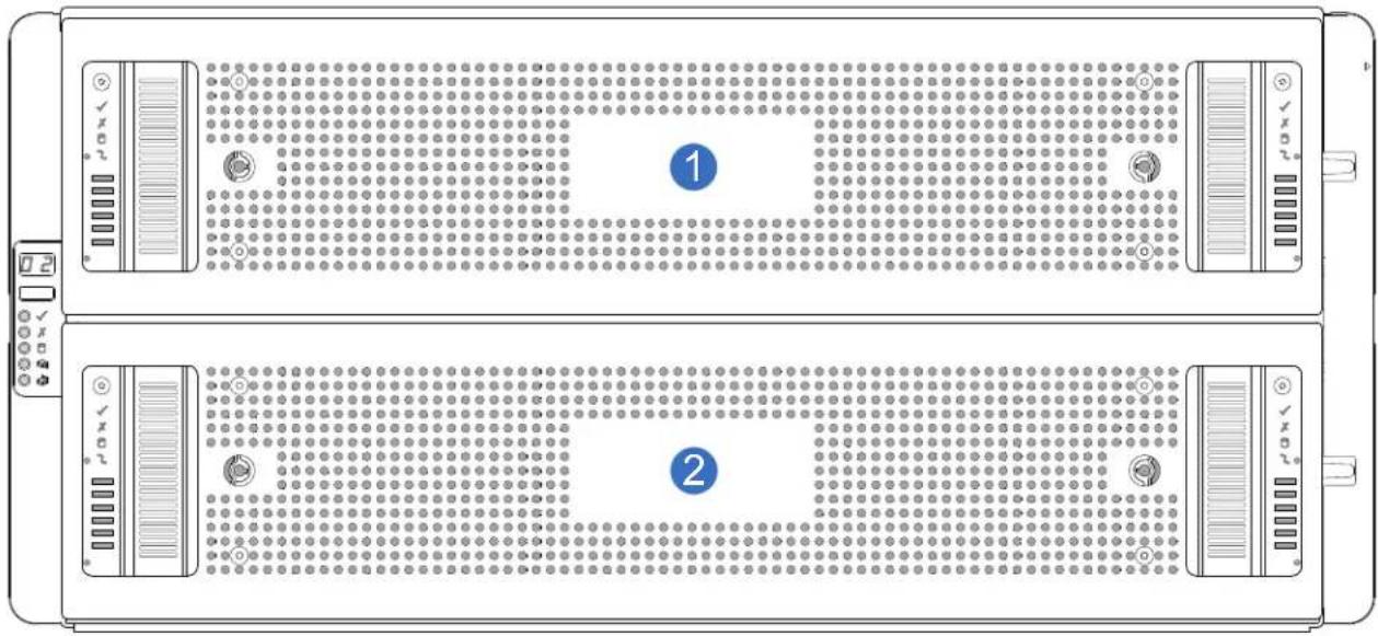
1 Drawer 0/Bezel
2 Drawer 1/Bezel
5U84 RAID Chassis/Expansion Chassis Drawer (Drives/CRUs)
Figure 120 provides an illustration of the 5U84 RAID or expansion chassis (drive slots view) with the drawer open. There are a total of 84 drive slots in the two drawers.
- Drawer 0 CRUs: all drives 0-41 are CRUs (42 drives can be installed)
- Drawer 1 CRUs: all drives 42-83 are CRUs (42 drives can be installed)
IMPORTANT: Drawer sideplanes—also known as side cards—can be hot-swapped as field-replaceable units (FRUs).
However, these FRUs require a special tool, and replacement should be performed by qualified service personnel only.
Contact your service provider for more information.
NOTE: Figure 120 displays the front of the drawer on the left side of the illustration. The back of the drawer is on the right side of the illustration.
Figure 120 5U84 RAID or Expansion Chassis Drives (CRUs)
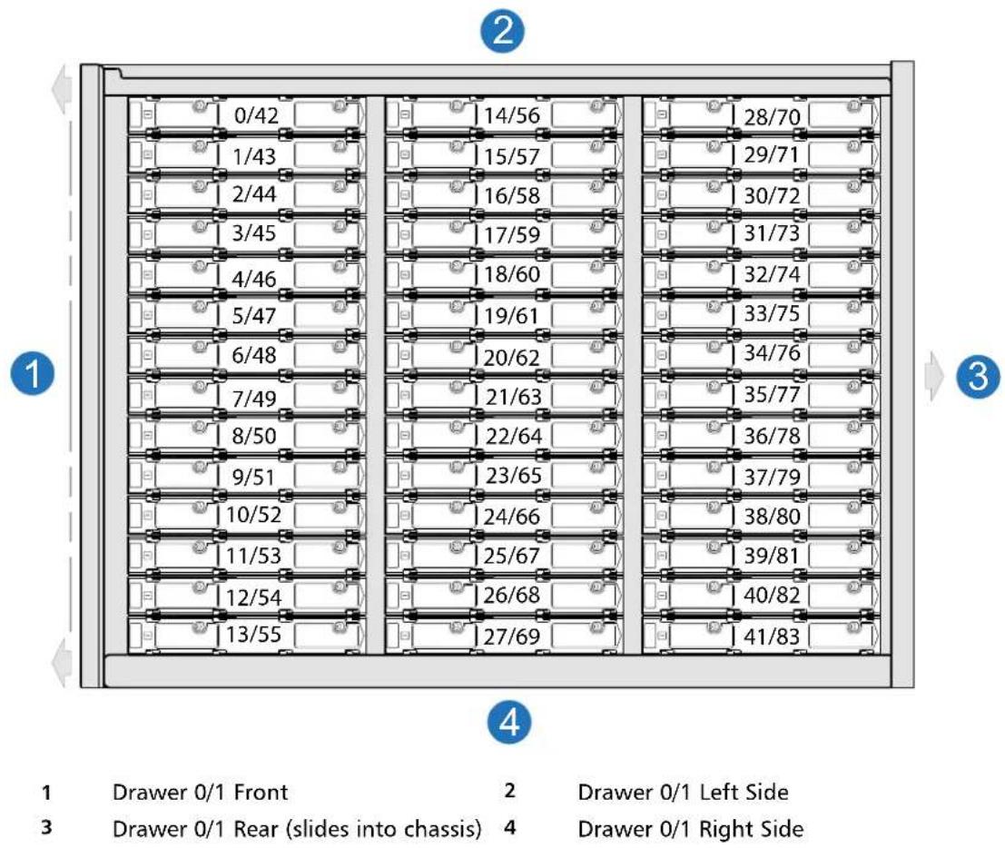
Table45 provides a list of CRUs in the 5U84 RAID chassis/expansion chassis.
Table 455U84 RAID Chassis/Expansion Chassis CRUs
| Item Chassis Component Description | |
| Disk Drive in Carrier (DDIC) | DDICs must be installed into drawers after delivery |
| • 2.5" disk with 3.5" adapter (disks of differing type/speed and storage capacity: SAS, SSD) | |
| • 3.5" disk (disks of differing type/speed and storage capacity: SAS, SSD) | |
| Additional CRUs Not Shown | |
| Chassis Sheet | metal chassis that is configurable as a RAID or expansion chassis |
| SFP* Small form | -pluggable (SFP) connectorsSFP transceiver: 8/16Gb/s FC; 10GbE iSCSI; 1Gb/s iSCSI |
| Rail Kit Variable | attachment options5U rack mount kit, shelf, long, all hardware |
| Cable Kit | Cable kit [Cable package: standard HD mini-SAS (SFF-8644) to HD mini-SAS (SFF-8644)] |
| Cable kit [Cable package: standard HD mini-SAS (SFF-8644) to mini-SAS (SFF-8088)] | |
| Cable kit [Cable package: USB Type B; CLI (USB)] | |
| AC Power Cord | AC power cord compatible with AC PSU(s) |
| *QXS-484 12G RAID chassis support FC and iSCSI SFPs used in combination. | |
NOTE: Figure 124 on page 161 provides a representative example of the controllers used in the RAID chassis.
Figure 125 on page 162 provides a representative example of the IOMs used in the expansion chassis.
The QXS-412 12G, QXS-424 12G, and QXS-484 12G systems use the same identical controllers and IOMs.
5U84 RAID Chassis CRUs (Rear View/Two CNC Controllers)
NOTE: Depending on customer requirements, the controllers can be CNC (FC or iSCSI) for host connection.
Refer to Figure 121 for all the 5U84 Raid chassis CRUs with CNC controllers.
Figure 121 5U84 RAID Chassis CRUs Rear View (CNC Controllers)
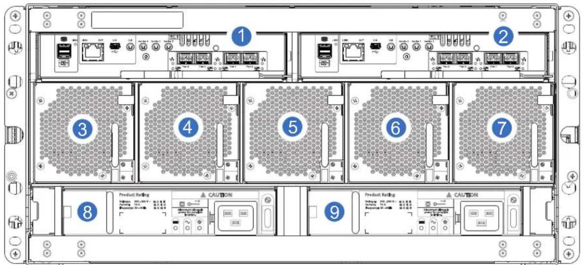
| 1 | Controller A | 2 | Controller B | 3 | Fan 0 |
| 4 | Fan 1 | 5 | Fan 2 | 6 | Fan 3 |
| 7 | Fan 4 | 8 | PSU 0 | 9 | PSU 1 |
5U84 Expansion Chassis CRUs (Rear View)
Figure 122 provides an illustration of the 5U84 expansion chassis rear view with two expansion IOMs (2-SAS ports used) installed.
Refer to Figure 122 for all the 5U84 expansion chassis CRUs with expansion IOMs.
NOTE: The 5U84 expansion chassis uses the same expansion IOMs as the 2U12 and 2U24 expansion chassis.
Figure 122 5U84 Expansion Chassis CRUs Rear View (SAS)
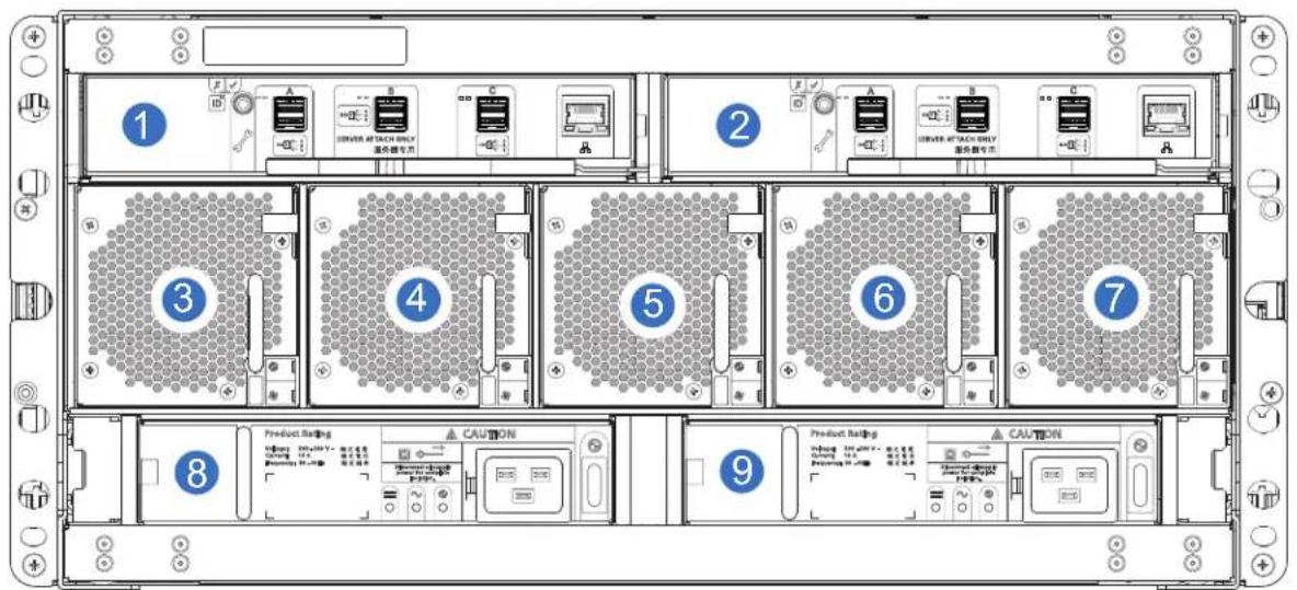
| 1 | IOM A | 2 | IOM B | 3 | Fan 0 |
| 4 | Fan 1 | 5 | Fan 2 | 6 | Fan 3 |
| 7 | Fan 4 | 8 | PSU 0 | 9 | PSU 1 |
RAID Controllers and Expansion IOMs for QXS 12G Systems
CNC Controller for RAID Chassis (2-Host Ports)
Figure 123 provides an illustration of a CNC controller used in the RAID chassis (2-Port FC/iSCSI module).
NOTE: This CNC controller is used within the QXS-312 12G and QXS-324 12G systems RAID chassis (2-host port systems).
Figure 123 Controller in RAID Chassis (2-Port FC/iSCSI module)
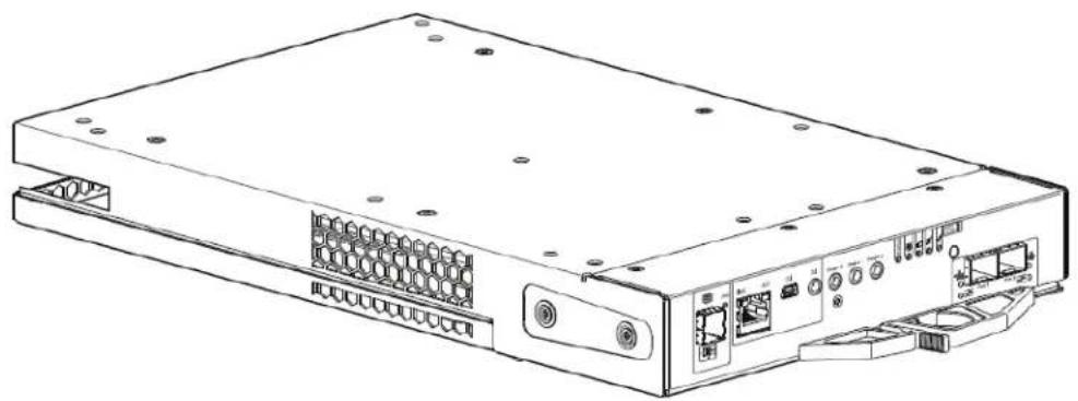
natural_image
Line drawing of a network switch device rear panel with ports and connectors (no text or labels)CNC Controller for RAID Chassis (4-Host Ports)
Figure 124 provides an illustration of a CNC controller used in the RAID chassis (4-Port FC/iSCSI module).
NOTE: This CNC controller is used within the QXS-412 12G, QXS-424 12G, and QXS-484 12G systems RAID chassis (4-host port systems).
Figure 124 Controller in RAID Chassis (4-Port FC/iSCSI module)
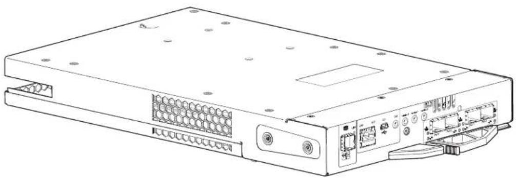
natural_image
Line drawing of a server rack with ports and connectors (no text or symbols)Expansion IOM for Expansion Chassis
Figure 125 provides an illustration of an expansion IOM used in the expansion chassis (3-Port SAS IOM)
Figure 125 Expansion IOM in Expansion Chassis (3-Port SAS Module)
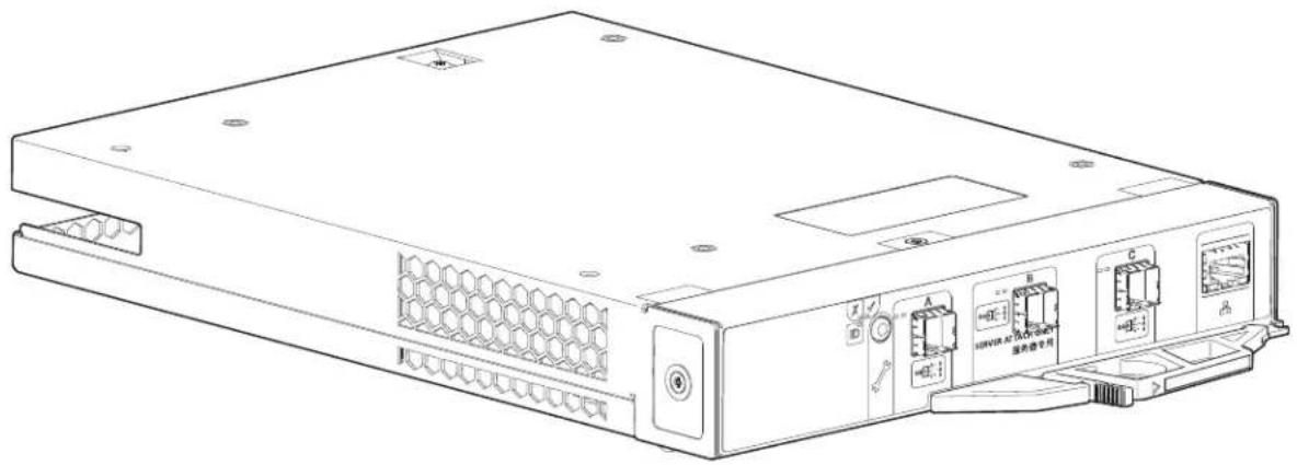
natural_image
Line drawing of a server rack with labeled ports and connectors (no text or symbols beyond labels)
natural_image
Abstract pattern of blue squares arranged in a grid on white background (no text or symbols)Chapter 6
Module Remove and Replace
This chapter provides information for the following QXS 12G systems:
• QXS-312 12G: 12-Drive (2-Port: FC or iSCSI)
• QXS-324 12G: 24-Drive (2-Port: FC or iSCSI)
• QXS-412 12G: 12-Drive (4-Port: FC or iSCSI)
• QXS-424 12G: 24-Drive (4-Port: FC or iSCSI)
• QXS-484 12G: 84-Drive (4-Port: FC or iSCSI)
Overview
This chapter provides procedures for replacing CRUs (customer-replaceable units), including precautions, removal instructions, installation instructions, and verification of successful installation. Each procedure addresses a specific task. Certain procedures refer to related documentation. See Related Documentation on page xi for a list of these documents.
CRU replacement procedures are grouped by chassis form factor as follow:
• 2U Chassis CRU Replacement on page 164
• 5U84 Chassis CRU Replacement on page 188
ESD Precautions
Before you begin any of the procedures, consider the following precautions and preventive measures.
Preventing ESD
To prevent electrostatic discharge (ESD) from damaging the system, be aware of the precautions to consider when setting up the system or handling parts. A discharge of static electricity from a finger or other conductor may damage system boards or other static-sensitive devices. This type of damage may reduce the life expectancy of the device.
CAUTION: Parts can be damaged by electrostatic discharge. Follow these precautions:
- Avoid hand contact by transporting and storing products in static-safe containers.
- Keep electrostatic-sensitive parts in their containers until they arrive at static-protected workstations.
- Place parts in a static-protected area before removing them from their containers.
- Avoid touching pins, leads, or circuitry.
• Always be properly grounded when touching a static-sensitive component or assembly. - Remove clutter (plastic, vinyl, foam) from the static-protected workstation.
Grounding Methods to Prevent ESD
Several methods are used for grounding. Adhere to the following precautions when handling or installing electrostatic-sensitive parts.
CAUTION: Parts can be damaged by electrostatic discharge. Use proper anti-static protection:
- Keep the replacement CRU in the ESD bag until needed; and when removing a CRU from the chassis, immediately place it in the ESD bag and anti-static packaging.
- Wear an ESD wrist strap connected by a ground cord to a grounded workstation or unpainted surface of the computer chassis.
- Wrist straps are flexible straps with a minimum of 1 megohm (± 10 percent) resistance in the ground cords.
- To provide proper ground, wear the strap snug against the skin.
- If an ESD wrist strap is unavailable, touch an unpainted surface of the chassis before handling the component.
- Use heel straps, toe straps, or boot straps at standing workstations. Wear the straps on both feet when standing on conductive floors or dissipating floor mats.
- Use conductive field service tools.
- Use a portable field service kit with a folding static-dissipating work mat.
If you do not have any of the suggested equipment for proper grounding, have an authorized technician install the part. For more information about static electricity or assistance with product installation, contact customer support.
2U Chassis CRU Replacement
This section cover CRU replacement for the 2U12 (QXS-312 12G and QXS-412 12G) and 2U24 (QXS-324 12G and QXS-424 12G) systems.
CAUTION: Unless noted otherwise within a passage pertaining to a particular CRU, the replacement procedure should be completed within two minutes of the removal of a defective module.
Removing a 2U Bezel
This is a representative example of removing the bezel from the 2U12 and 2U24 chassis. The removal of the 2U12 and 2U24 chassis bezel is the same process.
To remove the 2U12 or 2U24 bezel, complete the following steps:
1 Refer to Figure 126 on page 165, openings are provided between the vented grille and ear LEDs on the bezel.
2 While facing the front of the chassis, insert the index finger of each hand into the top of the respective (left or right) opening, and insert the middle finger of each hand into the bottom of the respective opening, with thumbs on the bezel's bottom.
3 Gently pull the top of the bezel while applying slight inward pressure below, to release the bezel from the ball studs.
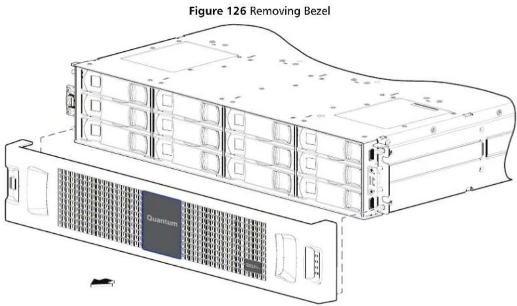
Installing a 2U Bezel
The 2U12 and 2U24 chassis ships without the bezels installed. This is a representative example of installing the bezel onto the 2U12 and 2U24 chassis. The installation of the 2U12 and 2U24 chassis bezel is the same process.
NOTE: Within the master chassis container, locate the long shallow/narrow box containing the bezel kit. The box lid should be labeled. Keep the bezel in the box until needed.
Figure 127 shows a pictorial view of a 2U12 chassis. The bezel attaches to the chassis face labeled "Front." The bezel installation process is the same for the 2U12 and 2U24 chassis.
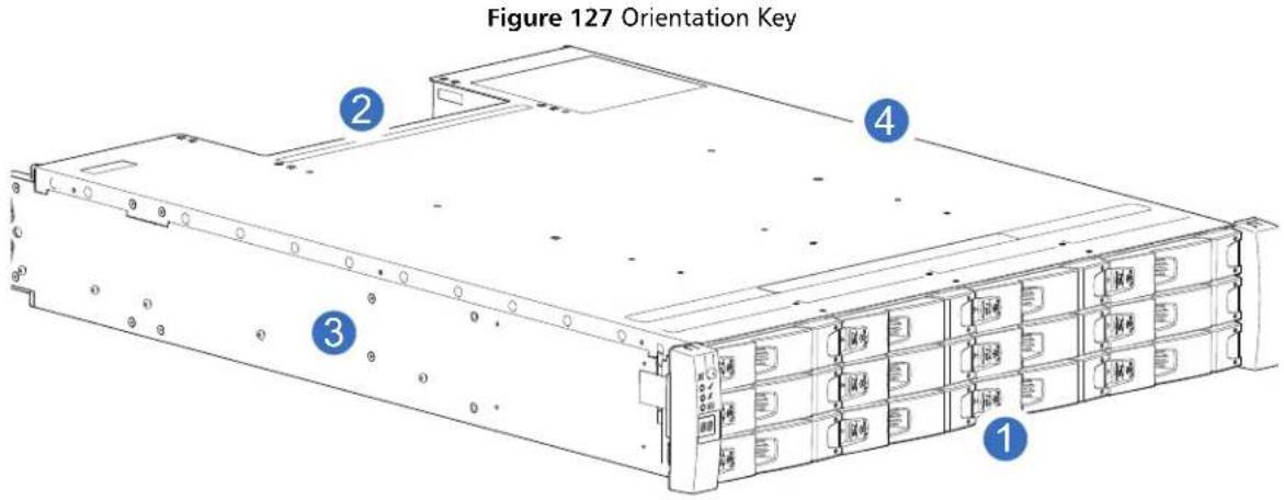
1 Front
2 Back
3 Left
4 Right
1 Identify the chassis to which the bezel will be attached.
Figure 127 shows a 2U12 chassis — with ears exposed — that is ready for bezel installation.
2 Open the box containing the bezel, and swing the lid back to reveal the bezel assembly packaged in foam. Remove the contents.
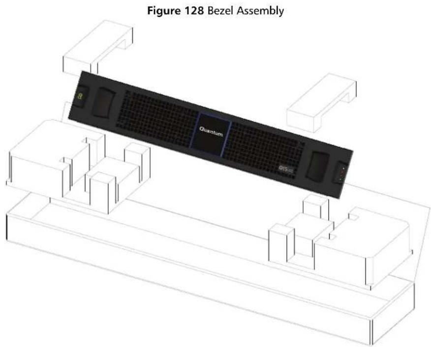
NOTE: Once you have removed the bezel assembly from its foam-packed box, examine it carefully, to verify that it is properly configured (with or without an air filter) to address your site requirements.
3 Orient the bezel assembly to align its back side with the front face of the chassis as shown in Figure 129.
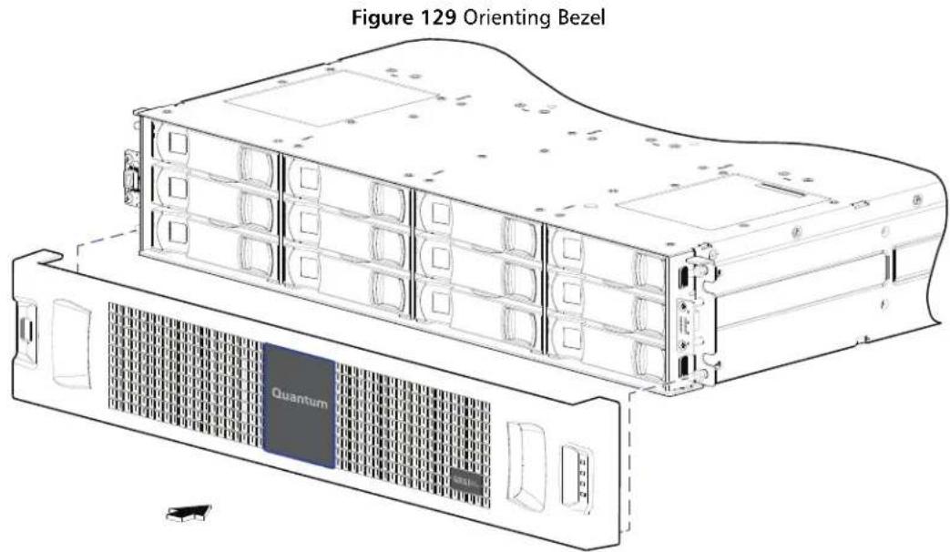
4 Face the front of the chassis, and while supporting the base of the bezel, gently slip the integrated ear covers onto the push-fit ball studs, taking care to guide the LED indicators through bezel openings.
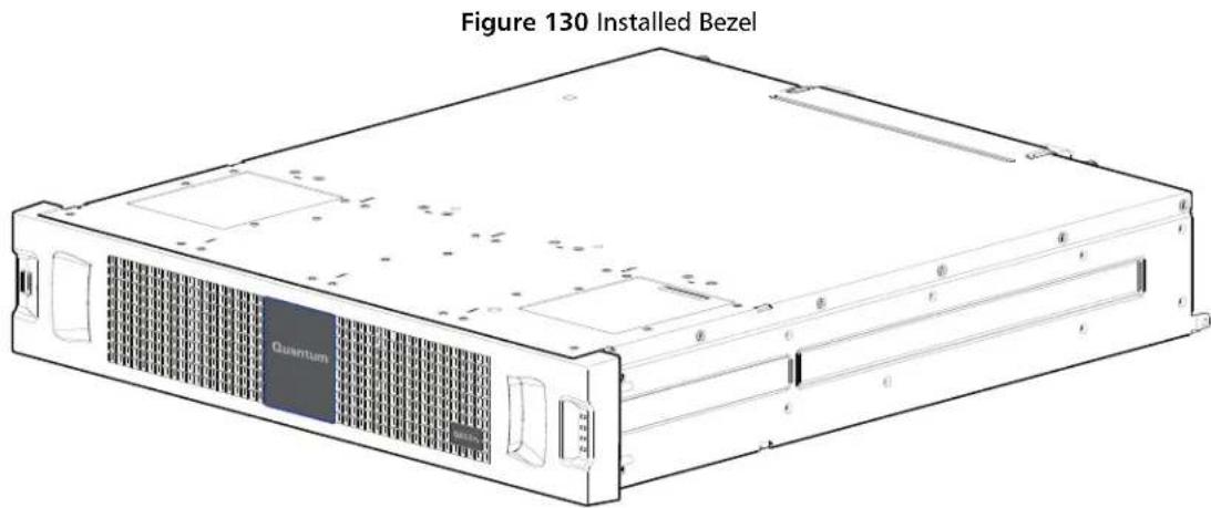
5 Gently push-fit the two ear cover areas of the bezel onto the ball studs to secure the bezel in place.
Replacing a 2U PSU
This section provides procedures for replacing a failed PSU. Illustrations in PSU replacement procedures show rear panel views of the chassis, with the PSU properly oriented for insertion into the rear panel of the chassis.
A single PSU is sufficient to maintain operation of the chassis. You need not halt operations and completely power-off the chassis when replacing only one PSU; however, a complete orderly shutdown is required if replacing both units simultaneously.
CAUTION: Do not remove the cover from the PSU due to danger from electric shock inside. Return the PSU to your supplier for repair.
See ESD Precautions on page 163 for additional ESD information.
TIP: The illustrations show PSU module replacement within the right slot as you view the chassis rear panel. To replace a PSU in the left slot, you would first rotate the module 180° about its longitudinal axis, so that it properly aligns with its connectors on the back of the midplane.
Removing a 2U PSU
CAUTION: Removing a PSU significantly disrupts the chassis airflow. Do not remove the PSU until you have received the replacement module. It is important that all slots are filled when the chassis is in operation.
Before removing the PSU, disconnect the power from the PSU by either the mains switch (where present) or by physically removing the power source in order to ensure your system has warning of imminent power shutdown.
- A faulty PSU must be replaced by a fully operational PSU within 24 hours.
- Ensure that you correctly identify the faulty PSU before beginning the step procedure.
Complete the following steps to remove a PSU.
1 Stop all I/O from hosts to the chassis. See also Stopping I/O on page 179.
TIP: This step is not required for hot-swapping. However, it is required when replacing both PSUs at once.
2 Use management software to shut down any other system components necessary.
TIP: This step is not required for hot-swapping. However, it is required when replacing both PSU at once.
3 Switch off the faulty PSU, and disconnect the power supply cable.
4 If replacing a single PSU via hot-swap, proceed to step 6.
5 If replacing both PSUs, verify that the chassis was shut down using management interfaces, and that the chassis is powered off.
6 Verify that the power cord is disconnected.
7 Grasp the latch and the side of the PSU handle between thumb and fore-finger, squeeze together and open the handle to pull the PSU out of the chassis as shown in Figure 131.
Figure 131 Removing a PSU
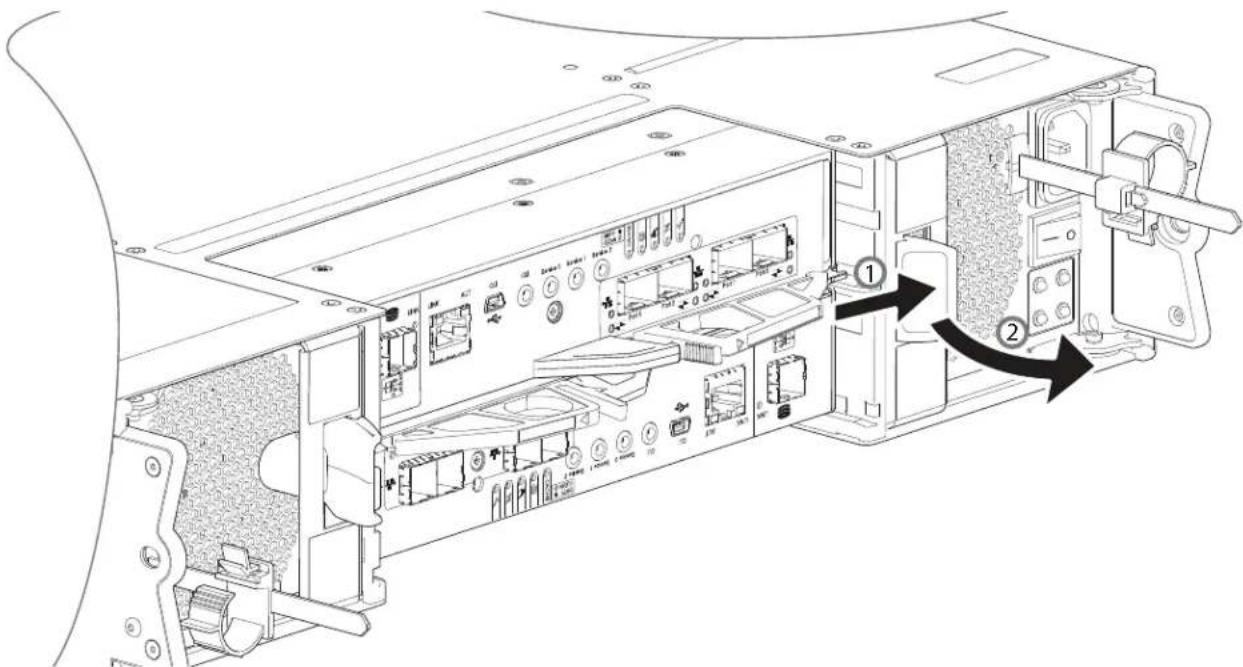
8 Grip the handle and withdraw the PSU, taking care to support the base of the module with both hands as you remove it from the chassis as shown in Figure 132.
Figure 132 Removing a PSU from Chassis
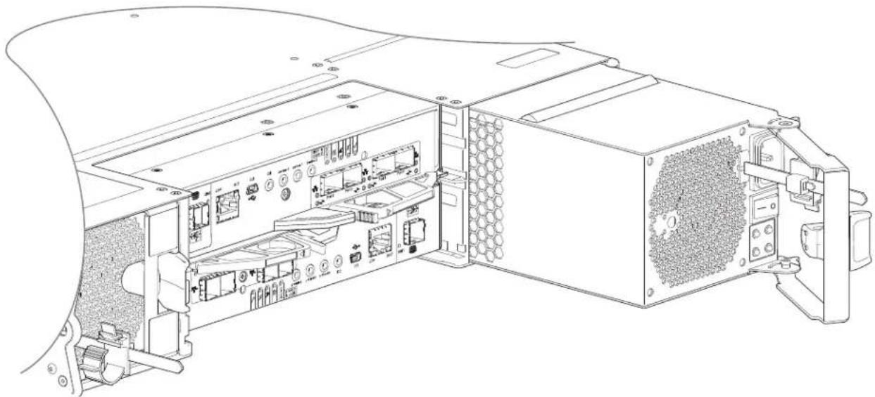
natural_image
Technical line drawing of an internal computer drive showing internal components and ports (no text or labels)IMPORTANT: Removing a PSU from a 2U RAID chassis and expansion chassis is the same process. This procedure applies to all 2U RAID chassis and expansion chassis.
9 If replacing two PSU, repeat steps 5 through 8, being mindful of the tips for step 1 and step 2.
Installing a 2U PSU
Refer to Figure 131 on page 169 and Figure 132 on page 169 when performing this procedure, but ignore the directional arrows—since you will insert the module into the slot—rather than extracting it from the chassis.
IMPORTANT: Handle the PSU carefully, and avoid damaging the connector pins. Do not install the PSU if any pins appear to be bent.
1 Check for damage, especially to all PSU connectors.
2 With the PSU handle in the open position, slide the module into the chassis, taking care to support the base and weight of the module with both hands.
3 Lock the module into its slot by manually closing the PSU handle.
You should hear a click as the latch handle engages and secures the PSU to its connector on the back of the midplane.
4 Connect the power cable to the power source and the PSU.
5 Secure the strain relief bales.
6 Using the management interfaces (the disk management utility (GUI) or CLI), verify whether the health of the new PSU is OK.
a Verify that the green PSU OK LED is on/blinking.
b Verify that cooling fans are spinning with no fail states.
c Verify that Ops panel states show no amber module faults.
7 If replacing two PSUs, repeat steps 1 through 5, being mindful of the tips for step 1 and step 2.
Replacing a 2U Drive Carrier Module
CAUTION: Always set up global spare drives to ensure that if a disk group fails, it can rebuild. Refer to the QXS 12G Disk Management Utility User Guide, Managing Global Spares.
A disk drive module consists of a drive in a carrier or sled. Drive modules are hot-swappable, which means they can be replaced without halting I/O to the disk groups, or powering off the chassis. The new drive must be of the same type, and possess capacity equal to or greater than the one being replaced. Otherwise, the storage system cannot use the new drive to reconstruct the disk group.
CAUTION: Removing a drive module impacts the airflow and cooling ability of the chassis. If the internal temperature exceeds acceptable limits, the chassis may overheat and automatically shut down or restart. To avoid potential overheating, wait 20 seconds to allow the internal drives to stop spinning, then insert the new drive module.
IMPORTANT: Familiarize yourself with FDE considerations relative to disk module installation and replacement. See also Full Disk Encryption (FDE) on page 65.
NOTE: When moving FDE-capable drive modules for a disk group, stop I/O to the disk group before removing the drive modules. Import the keys for the drives so that the drive content becomes available. See the QXS 12G Disk Management Utility User Guide or QXS 12G CLI Reference Guide for more information.
See ESD Precautions on page 163 for additional ESD information.
TIP: The illustrations show drive module replacement within the drive slots as you view the chassis front panel.
Removing a 2U 3.5" LFF Drive Carrier Module
1 Refer to Using the Anti-Tamper Locks on page 173 to unlock the anti-tamper lock on the drive module to allow removal of the drive module.
2 Press the latch in the carrier handle towards the handle hinge to release the carrier handle as shown in Figure 133.
Figure 133 Removing a Drive Module from Chassis-1
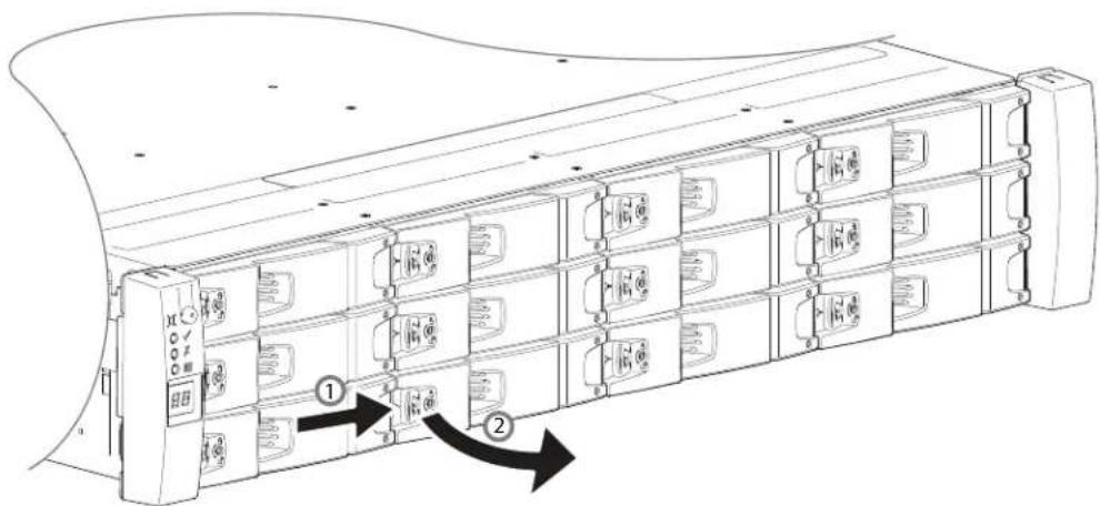
3 Gently move the drive carrier module approximately 25 mm (1-inch), then wait 30 seconds.
Figure 134 Removing a Drive Module from Chassis-2
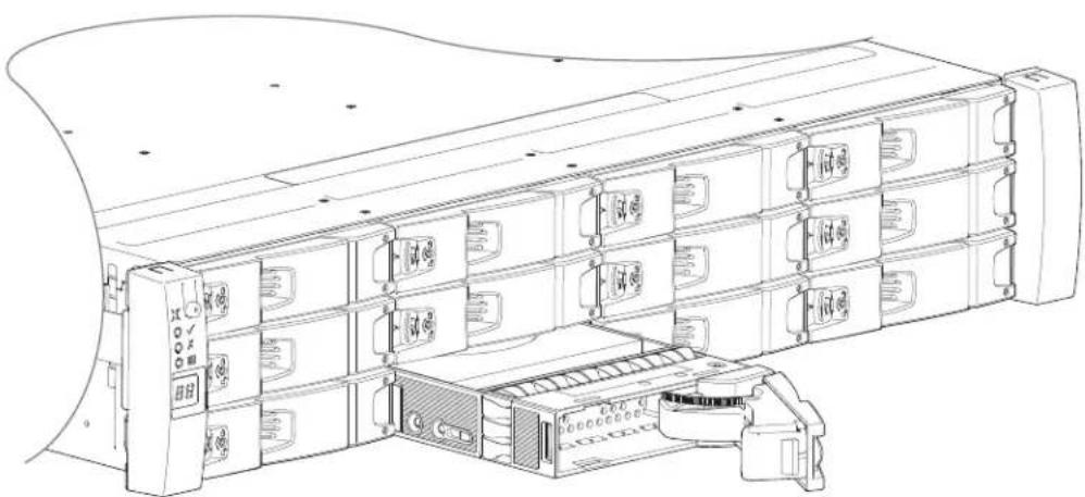
natural_image
Technical line drawing of a server rack unit with multiple drive bays and a central rack unit (no text or symbols visible)4 Remove the module fully from the drive slot.
CAUTION: To ensure optimal cooling throughout the chassis, drive blanks must be fitted to all unused drive slots.
Installing a 2U 3.5" LFF Drive Carrier Module
CAUTION: A drive carrier module cannot be installed if its anti-tamper lock is activated outside the chassis.
1 Release the drive carrier handle by depressing the latch in the handle.
Figure 135 3.5" LFF Drive Carrier Module in Open Position
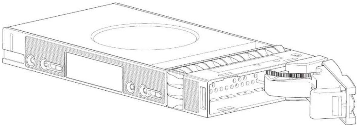
natural_image
Technical line drawing of a computer drive chassis showing internal components and casing (no text or labels)2 Insert the drive carrier module into the chassis.
Make sure that the drive carrier is positioned such that the top of the disk is facing up, and the handle opens from the left as you face the chassis front panel.
Figure 136 Installing a 3.5" LFF Drive Carrier Module-1
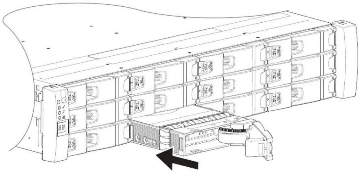
natural_image
Technical line drawing of a server rack with multiple drive units and a black arrow indicating a component (no text or symbols present)3 Slide the drive carrier fully into the chassis.
4 Cam the drive carrier home.
a The camming foot on the carrier will engage into a slot in the chassis.
b Continue to push firmly until the handle fully engages.
c You should hear a click as the latch handle engages and holds the handle closed.
Figure 137 Installing a 3.5" LFF Drive Carrier Module-2
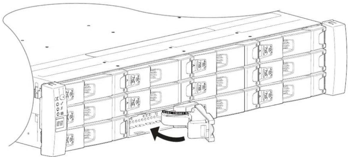
natural_image
Line drawing of a server rack with multiple drive bays and a mechanical device attached to the rack (no text or symbols)5 Using the management interfaces (the disk management utility (GUI) or CLI), verify whether the health of the new drive is OK.
a Verify that the Green Drive LED is on/blinking.
b Verify that Ops panel states show no amber module faults.
Using the Anti-Tamper Locks
The 3.5" LFF and 2.5" SFF drive modules provide anti-tamper locks. Refer to Figure 138 on page 174 when using this procedure.
1 Carefully put the T10 lock key into the cutout in the handle.
- The 3.5" LFF drive module is shown in Figure 138 on page 174.
- On 2.5" SFF drive modules, the socket is located between the latch and the carrier handle (Figure 139 on page 174).
• The lock socket mechanism is identical on both modules.
2 Position the key into its socket.
3 Perform one of the following actions to either activate or deactivate the anti-tamper lock:
a Lock: Rotate the key in a clockwise direction until the indicator is visible in the aperture beside the key.
b Unlock: Rotate the key in a counterclockwise direction until the indicator is visible in the aperture beside the key.
4 Remove the T10 lock key.
Figure 138 Activating Anti-Tamper Lock
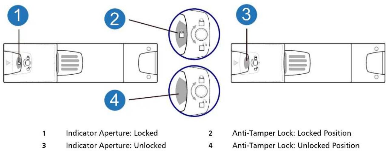
Removing a 2U 2.5" SFF Drive Carrier Module
The removal/replacement procedure for 2.5" SFF drive carrier modules is basically the same as for 3.5" LFF models, except that the 2.5" SFF carriers are mounted vertically.
1 Refer to Using the Anti-Tamper Locks on page 173 to unlock the anti-tamper lock on the drive module to allow removal of the drive module.
2 Press the latch in the carrier handle downward to release the carrier handle so that it can revolve outward as shown below.
Figure 139 Removing 2.5" SFF Drive Carrier Module-1
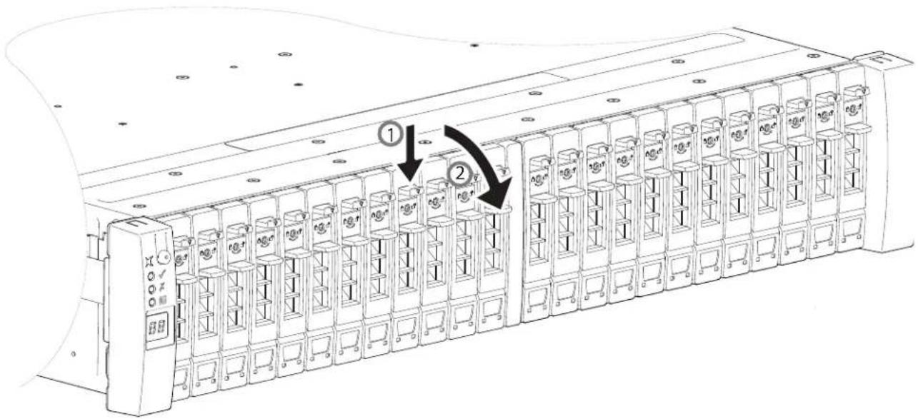
3 Gently move the drive carrier module outward from the drive slot.
Figure 140 Removing 2.5" SFF Drive Carrier Module-2
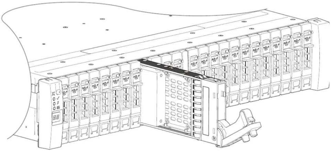
natural_image
Technical line drawing of an industrial control unit with multiple drive bays and a central storage unit (no text or labels visible)4 Remove the module fully from the drive slot.
CAUTION: To ensure optimal cooling throughout the chassis, drive blanks must be fitted to all unused drive slots.
Installing a 2U 2.5" SFF Drive Carrier Module
1 If the anti-tamper lock is engaged, unlock it per the instructions provided in Using the Anti-Tamper Locks on page 173.
2 Release the carrier handle by pressing the latch in the handle downwards, and opening the hinged handle as shown in Figure 141 on page 176.
3 Insert the carrier into the chassis in a vertical position.
IMPORTANT: Make sure the carrier is positioned such that the disk is on its left side and the handle opens from the top.
Figure 141 2/5" SFF Drive Carrier Module in Open Position
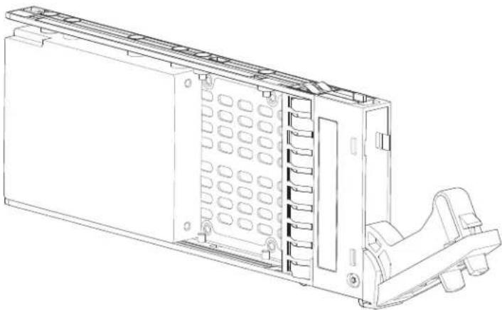
natural_image
Technical line drawing of a server rack unit with mounting bracket and clamping mechanism (no text or symbols)4 Slide the carrier fully into the chassis until it is stopped by the camming lever on the bottom of the carrier.
Figure 142 Installing a 2.5" SFF Drive Carrier Module-1
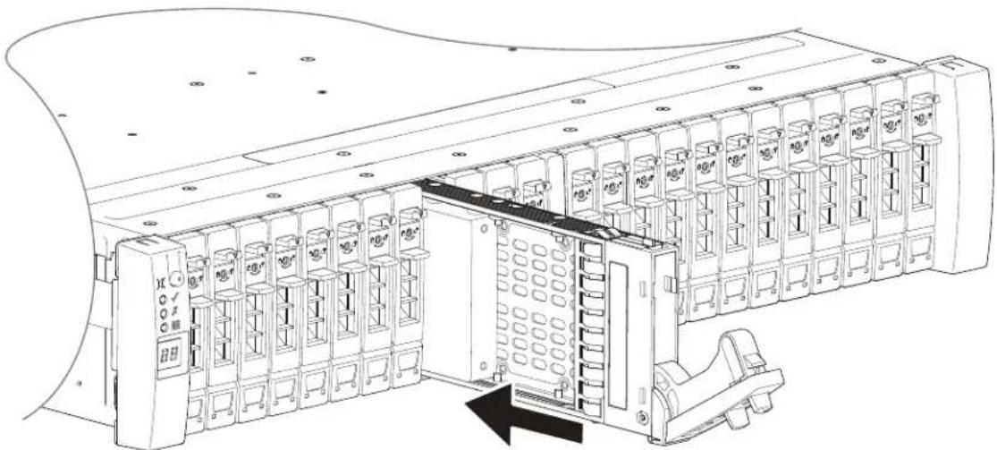
5 Cam the carrier home.
- The camming lever on the carrier will engage into the a slot in the chassis.
- Continue to push firmly until the handle fully engages.
- You should hear a click as the latch handle engages and holds the handle closed.
Figure 143 Installing a 2.5" SFF Drive Carrier Module-2
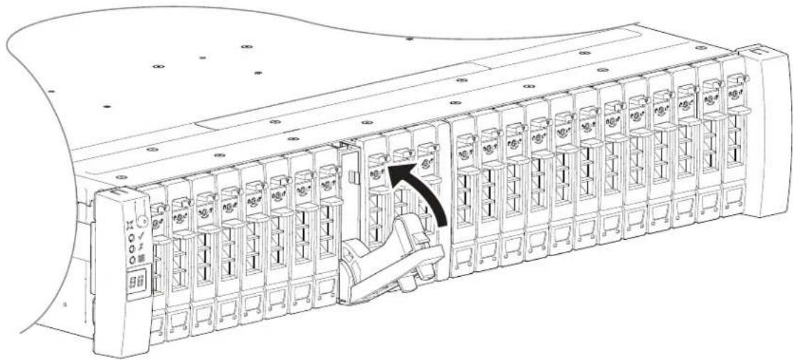
6 Using the management interfaces, the disk management utility (GUI) or CLI, verify whether the health of the new disk is OK.
- Verify that the Green Drive LED is on/blinking.
- Verify that Ops panel states show no amber module faults.
Replacing a 2U Drive Blank
A drive blank is removed from the chassis simply by pulling the module out of the drive slot. A drive blank is installed in the chassis by properly aligning it and inserting it into the drive slot, followed by pushing it securely into place.
CAUTION: To ensure optimal cooling throughout the chassis, drive blanks must be fitted to all unused drive slots in the 2U12 and 2U24 chassis.
Replacing a 2U RAID Controller or an Expansion IOM
IMPORTANT: The 2U QXS 12G CLI Reference Guidesystems support dual-controller configuration only. If a partner controller fails, the storage system will fail over and run on a single controller module until the redundancy is restored. A controller module must be installed in each controller slot to ensure sufficient air flow through the chassis during operation.
The RAID chassis uses two controller (for redundancy). The expansion chassis used two IOMs (for redundancy). In a dual-controller configuration, controller and expansion IOMs are hot-swappable, which means you can replace one module without halting I/O to disk groups, or powering off the chassis. In this case, the second module takes over operation of the storage system until you install the new module.
You may need to replace a controller module or an expansion IOM when:
• The Fault LED is illuminated.
• Health status reporting in the disk management utility (GUI) indicates a problem with the module.
- Events in the disk management utility (GUI) indicate a problem with the module.
- Troubleshooting indicates a problem with the module.
TIP: The illustrations show a RAID controller replacement within the top slot (A) as you view the chassis rear panel. The replacement of a RAID controller or an expansion IOM is the same process. To replace a RAID controller or an expansion IOM in the bottom slot (B), you would first rotate the module 180° about its longitudinal axis, so that it properly aligns with its connectors on the back of the midplane.
Before You Begin
Removing a RAID controller or expansion IOM from an operational chassis significantly changes air flow within the chassis.
- Openings must be populated for the chassis to cool properly.
- Leave modules in the chassis until ready to install a replacement.
- If replacing both RAID controllers in a dual-controller chassis, use the disk management utility (GUI) to record configuration settings before installing the new RAID controllers.
- See Removing a 2U RAID Controller or an Expansion IOM on page 181, and Installing a 2U RAID Controller or an Expansion IOM on page 182 for instructions on installing an additional controller module.
CAUTION: When replacing a controller module, ensure that less than 10 seconds elapse between inserting it into a slot and fully latching it in place. Not doing so might cause the controller to fail. If it is not latched within 10 seconds, remove the controller module from the slot, and repeat the process.
When two controller modules are installed in the chassis, they must be of the same model type. When replacing both controller modules in an operational chassis, follow these guidelines:
1 Replace one controller as described in these instructions.
2 Wait 30 minutes: this pause ensures that the controller and its ownership of disk groups has sufficient time to stabilize. See also Verifying Component Operation on page 183.
3 Check the system status and event logs to verify that the system is stable.
4 Replace the partner controller as described in these instructions.
Configuring Partner Firmware Update
In a dual-controller system in which partner firmware update (PFU) is enabled, when you update firmware on one controller, the system automatically updates the partner controller. Disable partner firmware update only if requested by a service technician.
Use the disk management utility (GUI) or CLI to change the PFU setting.
IMPORTANT: See the "Updating firmware" topic within the QXS 12G Disk Management Utility User Guide before performing a firmware update.
NOTE: The disk management utility (GUI) and CLI provide an option for enabling or disabling Partner Firmware Update for the partner controller as described in the Storage Management Guide. To enable or disable the setting via the CLI, use the set advanced-settings command, and set the partner-firmware-upgrade parameter. See the QXS 12G CLI Reference Guide for more information about command parameter syntax.
Verifying Component Failure
Select from the following methods to verify component failure:
- Use the disk management utility (GUI) to check the health icons/values of the system and its components to either ensure that everything is okay, or to drill down to a problem component.
- The disk management utility (GUI) uses health icons to show OK, Degraded, Fault, or Unknown status for the system and its components.
- If you discover a problem component, follow the actions in its Recommendation field to resolve the problem.
- As an alternative to using the disk management utility (GUI), you can run the CLI show system command to view the health of the system and its components.
- If any component has a problem, the system health will be Degraded, Fault, or Unknown.
- If you discover a problem component, follow the actions in its Health Recommendations field to resolve the problem.
- Monitor event notification — With event notification configured and enabled, use the disk management utility (GUI) to view the event log, or run the CLI show events detail command to see details for events.
- Check Fault LED (back of chassis on the RAID controller or expansion IOM face plate): Amber = Fault condition.
- Check that the OK LED (back of chassis) is off.
Stopping I/O
When troubleshooting drive and connectivity faults, stop I/O to the affected disk groups from all hosts as a data protection precaution. As an additional data protection precaution, it is helpful to conduct regularly scheduled backups of your data.
IMPORTANT: Stopping I/O to a disk group is a host-side task, and falls outside the scope of this document.
When on-site, you can verify that there is no I/O activity by briefly monitoring the system LEDs; however, when accessing the storage system remotely, this is not possible. Remotely, you can use the show disk-group-statistics command to determine if input and output has stopped. Perform these steps:
1 Using the CLI, run the show disk-group-statistics command.
The Reads and Writes fields show the number of these operations that have occurred since the statistic was last reset, or since the controller was restarted. Record the numbers displayed.
2 Run the show disk-group-statistics command a second time.
This provides you a specific window of time (the interval between requesting the statistics) to determine if data is being written to or read from the disk group. Record the numbers displayed.
3 To determine if any reads or writes occur during interval, subtract the set of numbers you recorded in step 1 from the numbers you recorded in step 2.
- If the resulting difference is zero, then I/O has stopped.
- If the resulting difference is not zero, a host is still reading from or writing to this disk group.
- Continue to stop I/O from hosts, and repeat step 1 and step 2 until the difference in step 3 is zero.
NOTE: See the QXS 12G CLI Reference Guide for additional information. Optionally, you can use the disk management utility (GUI) to monitor IOPs and MB/s.
Shutting Down a Controller Module
Shutting down the controller in a RAID chassis ensures that a proper failover sequence is used, which includes stopping all I/O operations and writing any data in write cache to disk.
- If both controller modules are shut down, hosts cannot access the system's data.
- Perform a shut down before you remove a controller module from a chassis, or before you power off its chassis for maintenance, repair, or a move.
- Use the disk management utility (GUI) or the CLI to perform a shutdown.
Using the Disk Management Utility (GUI)
1 Sign-in to the disk management utility (GUI).
2 In the System panel in the banner, select Restart System.
The Controller Restart and Shut Down panel opens.
3 Select the Shut Down operation, which automatically selects the controller type Storage.
4 Select the controller module to shut down: A, B, or both.
5 Select OK. A confirmation panel appears.
6 Select Yes to continue; otherwise, select No. If you selected Yes, a message describes shutdown activity.
NOTE: If an iSCSI port is connected to a Microsoft Windows host, the following event is recorded in the Windows event log: Initiator failed to connect to the target.
NOTE: See the QXS 12G Disk Management Utility User Guide for additional information.
Using the CLI
1 Log-in to the CLI.
2 In your dual-controller system, verify that the partner controller is online by running the command;
show controllers
3 Shut down the failed controller—A or B—by running the command: shutdown a or shutdown b
The blue OK to Remove LED (back of chassis) illuminates to indicate that the controller module can be safely removed.
4 Illuminate the white Identify LED of the chassis that contains the controller module to remove by running the command:
set led enclosure 0 on
The Display LED on the Ops panel located on the chassis left ear will be blinking green when the above command is invoked.
NOTE: See the QXS 12G CLI Reference Guide for additional information.
Removing a 2U RAID Controller or an Expansion IOM
IMPORTANT: Considerations for removing controller modules:
- In a dual-controller environment, you may hot-swap a single controller module in an operational chassis, provided you first shut down the faulty controller using the disk management utility (GUI) or the CLI.
- In a dual-controller environment—if replacing both controller modules—you must adhere to the instructions provided in Before You Begin on page 178.
- Do not remove a faulty module unless its replacement is on-hand. All modules must be in place when the system is in operation.
Comply with all ESD precautions. Refer to ESD Precautions on page 163 for additional information.
Illustrations in the controller module replacement procedures show rear panel views of the chassis. Ensure the RAID controllers and/or expansion IOMs are properly aligned for insertion into the proper slots.
1 Verify that you have successfully shut down the controller module using the disk management utility (GUI) or the CLI.
2 Locate the chassis whose UID LED (Ops panel on chassis front left ear) is illuminated, and within the chassis, locate the controller module whose OK to Remove LED is blue (rear panel).
3 Disconnect any cables connected to the controller.
Label each cable to facilitate re-connection to the replacement RAID controller or expansion IOM.
4 Grasp the module latch between the thumb and forefinger, and squeeze the flange and handle together to release the latch handle from its docking member (detail No.1), and swing the latch out to release the RAID controller or expansion IOM from its seated position (detail No.2) as shown in Figure 144 and Figure 145.
Figure 144 Controller or IOM Latch Operation

natural_image
Technical illustration of two mechanical components with directional arrows indicating movement (no text or symbols)5 Swing the latch handle open as shown in detail No.2 within Figure 144 and Figure 145.
Figure 145 Removing a Controller or Expansion IOM
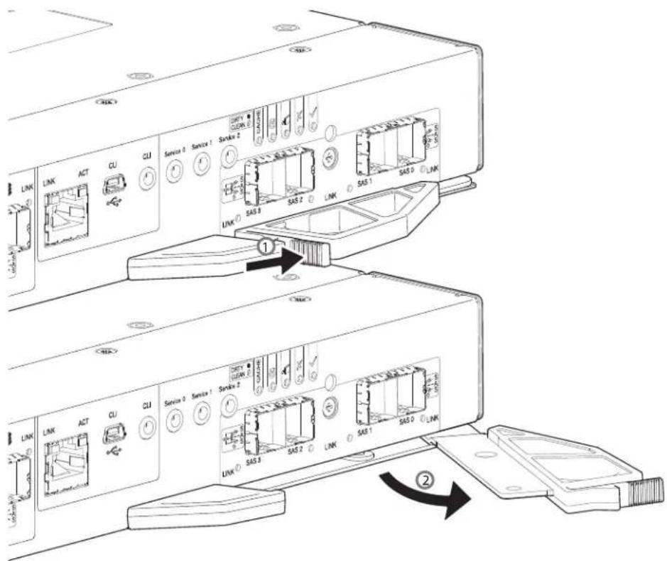
6 Grip the latch handle and ease the RAID controller or expansion IOM forward from the slot as shown in detail No.2 within Figure 145.
NOTE: The illustration above shows a 4-port controller module. However, the procedure applies to all RAID controllers and expansion IOMs discussed herein. They all use the same latch mechanism, but feature different faceplate geometry.
7 Place both hands on the canister body, and pull it straight out of the chassis such that the RAID controller or expansion IOM remains level during removal.
Installing a 2U RAID Controller or an Expansion IOM
Comply with all ESD precautions. Refer to ESD Precautions on page 163 for additional information.
CAUTION: If passive copper cables are connected, the cable must not have a connection to a common ground/earth point.
NOTE: When performing the following procedure, refer to Figure 145 on page 182 while ignoring the directional arrow. For installation, the RAID controller or expansion IOM will travel in the opposite direction relative to the arrow shown.
1 Examine the RAID controller or expansion IOM for damage, and closely inspect the interface connector.
Do not install if the pins are bent.
2 Grasp the RAID controller or expansion IOM using both hands, and with the latch in the open position, orient the module and align it for insertion into the target slot.
3 Ensuring that the RAID controller or expansion IOM is level, slide it into the chassis as far as it will go.
A controller module that is only partially seated will prevent optimal performance of the RAID chassis. Verify that the controller module is fully seated before continuing.
4 Set the module in position by manually closing the latch.
You should hear a click as the latch handle engages and secures the RAID controller or expansion IOM to its connector on the back of the midplane.
5 Reconnect the cables.
NOTE: In a dual-controller system in which PFU is enabled, when you update the firmware on one controller, the system automatically updates the partner controller.
Verifying Component Operation
RAID Controller
After replacing the controller module, verify that the CRU OK LED (rear panel) illuminates green, indicating that the controller has completed initializing, and is online/operating normally.
- It may take two to five minutes for the replacement controller to become ready.
- If you are replacing either controller module, and PFU is enabled, you may need to wait 30 minutes to ensure that the two controllers—with their respective ownership of the disk groups—have enough time to fully stabilize.
IMPORTANT: Use the disk management utility (GUI) or CLI to perform a restart only if necessary. See the topic about restarting controllers in the QXS 12G Disk Management Utility User Guide for more information.
Expansion IOM
If the storage system is configured with expansion chassis, the replacement expansion IOM may take up to one minute to initialize after the cables are connected. Verify that firmware on both expansion IOMs is compatible and current.
NOTE: See the topic about updating expansion chassis IOM firmware within the QXS 12G Disk Management Utility User Guide.
Replacing a 2U Storage Chassis
The RAID chassis or expansion chassis replacement procedure replaces a damaged chassis CRU. The procedure includes removing all CRU modules from a damaged chassis and installing them into a replacement chassis.
IMPORTANT: The QXS 12G CLI Reference Guide systems using 2U12 or 2U24 chassis are described in Customer-Replaceable Units on page 145.
Whether your RAID chassis product is a 2U12 or 2U24 model, a fully functional replacement chassis requires the successful removal and installation of the following components:
- All power and data cables
- All drive modules
- Two PSUs (both AC)
- Two controllers of the same model type
This procedure references the CRU component procedures described elsewhere in this chapter.
Before You Begin
CAUTION: Do not remove the chassis until you have received the replacement chassis.
Comply with all ESD precautions. Refer to ESD Precautions on page 163 for additional information.
1 Schedule down time that will allow for shutdown; sixty minutes of replacement work; and restart.
2 Verify the existence of a known/good backup of the system.
3 Record system settings for future use and label all cables.
4 Prepare a suitable static-protected work environment to accommodate chassis replacement.
Verifying Component Failure
The RAID chassis CRU includes the chassis metal housing, the module runner system, the integrated Ops panel, and the assembled/installed midplane PCB that connects controller modules, drive modules, and PSUs. See the empty chassis pictorials: 2U12–Front of 2U12 RAID or Expansion Chassis on page 21 and 2U24–Front of 2U24 RAID or Expansion Chassis on page 22.
This CRU replaces an chassis that has been damaged, or whose midplane has been damaged. Often, a damaged midplane will appear as though a RAID controller has failed. If you replace a controller module and it does not remedy the fault, you may need to replace the chassis.
You can observe chassis health (front panel and rear panel) using management interfaces to verify chassis/component failure or chassis/component operation. See also Using Management Interfaces on page 188.
Preparing to Remove a Damaged 2U Chassis
Because you are removing and replacing an entire storage chassis, neither the hot-swap capability that applies to replacing individual redundant CRUs in an operational storage chassis, nor the hot-add of an expansion chassis to an operational storage system, apply to this procedure.
1 Stop all I/O from hosts to the system. See also Stopping I/O on page 179.
2 Shut down the controllers. See also Shutting Down a Controller Module on page 180.
3 Power off the system – RAID chassis first; expansion chassis next. see Powering On/Powering Off on page 105.
Table 46 Replacing a 2U Chassis and Installing CRUs
| To accomplish this sequential process: See the following procedures: | |||
| 1 | Remove the chassis bezel. | Removing a 2U Bezel on page 165 | |
| 2 Facing the front of the 2U chassis:a Remove the drive modules (label slot number of each drive) from the damaged chassis. ^1 & 3 Note: Drives must be placed within the same slot number in the new chassis.b Place the drives in a static-protected work area nearby. ^1 & 3 | a | Removing a 2U 3.5” LFF Drive Carrier Module on page 171 | |
| b | Removing a 2U 2.5” SFF Drive Carrier Module on page 174 | ||
| 3 Facing the rear of the 2U chassis, remove the power and data cables. | Preparing to Remove a Damaged 2U Chassis on page 184 (step 1, step 2, and step 3) | ||
| 4 Remove the damaged storage chassis from the rack. | Preparing to Remove a Damaged 2U Chassis on page 184 | ||
| 5 Remove the two PSUs from the damaged chassis rear panel, and install them in the replacement chassis. | a | See PSU related TIP on Removing a 2U PSU on page 168. | |
| b | Removing a 2U PSU on page 168 | ||
| c | Installing a 2U PSU on page 170 | ||
| 6 Remove the two controllers or expansion IOMs from the damaged chassis rear panel, and install them in the replacement chassis. ^2 | a | Replacing a 2U RAID Controller or an Expansion IOM on page 177 | |
| b | Removing a 2U RAID Controller or an Expansion IOM on page 181 | ||
| c | Installing a 2U RAID Controller or an Expansion IOM on page 182 | ||
| d | Verifying Component Operation on page 183 | ||
| 7 Install the replacement storage chassis in the rack. | Installing the Replacement 2U Chassis in the Rack on page 186 | ||
| 8 Facing the front of the 2U chassis, install drive modules into the replacement chassis. ^3 | a | Full Disk Encryption (FDE) on page 65 | |
| b | Installing a 2U 3.5” LFF Drive Carrier Module on page 172 | ||
| c | Installing a 2U 2.5” SFF Drive Carrier Module on page 175 | ||
| 9 Install the bezel. | Installing a 2U Bezel on page 165 | ||
| 10 Complete the chassis replacement process. | Completing the Process on page 187 | ||
Table46 Notes:
^1 If you temporarily stack the drives before installing them, insert static dissipative foam between the drive modules.
^2 Within the replacement chassis, each controller or expansion IOM must be reinstalled into the same controller or expansion IOM slot from which it was extracted from the damaged chassis (0A > 0A and 0B > 0B, respectively). For FC/iSCSI controllers, the SFPs installed in the CNC ports need not be removed. For SFP replacement, see SFP Option for CNC Ports on page 229.
^3 Within the replacement chassis, reinstall each drive or drive blank into the same drive slot from which it was removed from the damaged chassis. To ensure optimal cooling throughout the chassis, drive blanks must be fitted to all unused drive slots.
Removing a Damaged 2U Chassis from the Rack
This section provides a procedure for removing a damaged chassis from its rack location.
CAUTION: It is recommended that all drive modules be removed before removing the chassis. Two people are required to move the 2U chassis.
1 Disconnect the power cables and data cables between devices as needed:
a Between the cascaded chassis.
b Between the controller and peripheral SAN devices.
c Between the controller and the host.
NOTE: Label the cables to facilitate reconnection of the storage devices.
2 Remove the retaining screws that secure the front and rear of the chassis to the rack and rails.
NOTE: Do not remove the ear components from the failed chassis: integrated ear components and covers are provided with the replacement chassis CRU.
3 Maintaining a level position, carefully slide the chassis from the rack.
4 Place the chassis on a static-protected work surface near the replacement chassis, with the removed drive modules and screws.
Installing the Replacement 2U Chassis in the Rack
CAUTION: If any licenses other an Q-Tier (virtualization) were installed on the system, after chassis swap, customer must obtain a new license set tied to the new OEM serial number. Refer to the QXS 12G CLI Reference Guide to obtain the license set. Also, differentiate the TLA serial number from the OEM serial number.
This section provides a procedure for installing the replacement chassis in its rack location.
IMPORTANT: Refer to Installing 2U Chassis on page 62 when installing the chassis into the rack.
IMPORTANT: Install the chassis into the rack before re-inserting the drive modules. Two people are required to move the chassis.
1 Support the bottom of the chassis. Carefully lift/align the chassis and while maintaining a level position for the chassis, slide it into the rack.
2 Using the appropriate mounting hardware, secure the chassis to the rack.
3 Using the applicable retaining screws, secure the front and rear of the chassis to the rack and rails.
Completing the Process
This section provides a procedure for ensuring that the CRU components installed in the replacement RAID chassis function properly.
1 Reconnect data cables between devices, as needed, to return to the original cabling configuration:
- Between cascaded storage expansion chassis.
- Between the controllers (RAID chassis) and peripheral or SAN devices.
- Between the RAID chassis and the host.
2 Reconnect power cables to the storage chassis – Powering On/Powering Off on page 105.
Verifying Component Operation
1 Restart system devices by moving the power switch on the power supply to the On position in the following sequence:
a Expansion chassis first.
b RAID chassis next.
c Data host last (if powered down for maintenance purposes).
Allow time for each device to complete its Power On Self Tests (POST) before proceeding.
2 Perform a rescan to force a fresh discovery of all expansion chassis connected to the RAID chassis.
- This step clears the internal SAS layout information, reassigns chassis IDs, and ensures the chassis are displayed in the proper order.
- Use the CLI or disk management utility (GUI) to perform the rescan:
- This step clears the internal SAS layout information, reassigns chassis IDs, and ensures the chassis are displayed in the proper order. - Use the CLI or disk management utility (GUI) to perform the rescan:
To perform a rescan using the CLI, enter the following command: rescan
To perform a rescan using the disk management utility (GUI):
a Verify that both controllers are operating normally.
b In the System topic, select Action > Rescan Disk Channels.
c Select Rescan.
Using LEDs
View LEDs on the chassis front and rear panels.
- Verify front panel LEDs
-
Front panel LEDs reside on the Ops panel located on the left ear flange. Disk LEDs are located on the carrier modules.
-
Verify that the System Power On/Standby LED is illuminated green, and that the Module Fault LED is not illuminated.
- Verify that the chassis ID LED located on the left ear is illuminated green.
- Verify that the drive module's Green LED is illuminated green or blinking green, and that the drive module's Amber LED is not illuminated.
- Verify rear panel LEDs
- Rear panel LEDs reside on PSUs and RAID controller/expansion IOM face plates.
- Verify that each PSU OK LED is illuminated green.
- For RAID controllers/expansion IOMs, verify that the OK LED is illuminated green, indicating that the module has completed initializing, and is online.
Using Management Interfaces
In addition to viewing LEDs as described above, you can use management interfaces to monitor the health status of the system and its components, provided you have configured and provisioned the system, and enabled event notification.
Select from the following methods to verify component operation:
- Use the disk management utility (GUI) to check the health icons/values of the system and its components to either ensure that everything is okay, or to drill down to a problem component.
- The disk management utility (GUI) uses health icons to show OK, Degraded, Fault, or Unknown status for the system and its components.
- If you discover a problem component, follow the actions in its Recommendation field to resolve the problem.
- As an alternative to using the disk management utility (GUI), you can run the show system command in the CLI to view the health of the system and its components.
- If any component has a problem, the system health will be Degraded, Fault, or Unknown.
- If you discover a problem component, follow the actions in its Health Recommendations field to resolve the problem.
Monitor event notification — With event notification configured and enabled, you can view event logs to monitor the health of the system and its components.
- If a message tells you to check whether an event has been logged, or to view information about an event in the log, you can do so using the disk management utility (GUI) or the CLI.
- Using the disk management utility (GUI), you would view the event log and then hover over the event message to see detail about that event.
- Using the CLI, you would run the show events detail command (with additional parameters to filter the output) to see the detail for an event (see the QXS 12G CLI Reference Guide for more information about command parameters and syntax).
5U84 Chassis CRU Replacement
This section covers the 5U84 (QXS-484 12G) chassis CRU replacement.
NOTE: Unless noted otherwise within a passage pertaining to a particular CRU, the replacement procedure should be completed within two minutes of the removal of a defective module.
Accessing 5U84 Drawers
To observe or replace a DDIC, you must open the drawer in which it resides. The top drawer (Drawer 0) and the bottom drawer (Drawer 1) are accessed from the chassis front panel. See also Front of 5U84 RAID or Expansion Chassis on page 23 and 5U84 RAID or Expansion Chassis Drive Slots on page 24.
Opening a 5U84 Drawer
1 Verify that the anti-tamper locks are not engaged.
- The red arrows on the locks point inwards if the locks are disengaged as shown in Figure 146.
- If necessary, unlock them by rotating counter-clockwise using a Torx T20 bit.
Figure 146 Drawer/Bezel LED Panel
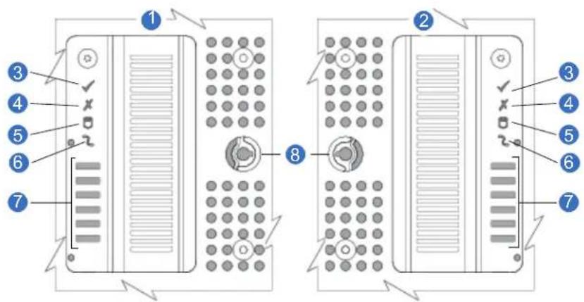
1 Left Side of Chassis
2 Right Side of Chassis
3 Sideplane OK/Power Good
4 Drawer Activity
5 Logical Fault
6 Cable Fault
7 Drawer Activity Indicators
Bar Graph
8 Anti-tamper Lock
2 Push the drawer latches inward and hold them as shown in Figure 147.
Figure 147 Opening a Drawer-1
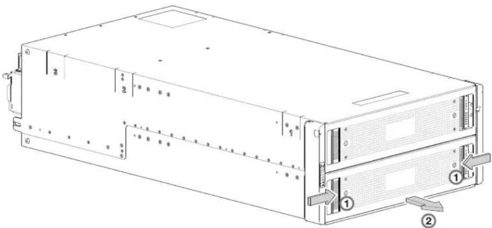
natural_image
Technical line drawing of a server rack with labeled components (no text or symbols present)3 Pull the drawer outward until it locks at the drawer stops as shown in Figure 148. The drawer is shown empty, which is how the chassis is delivered.
Figure 148 Opening a Drawer-2
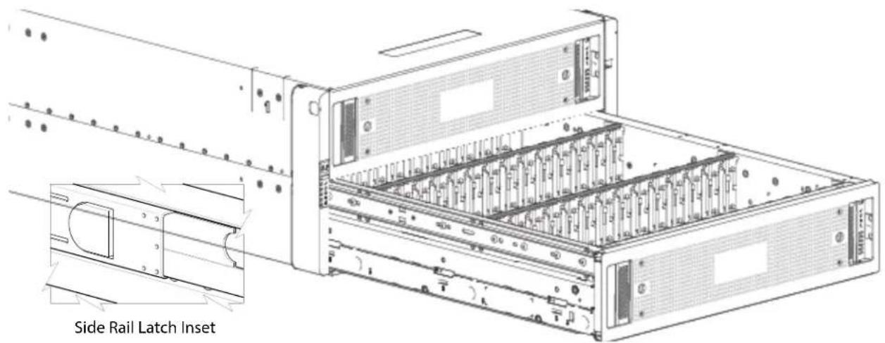
IMPORTANT: The drawer must not remain open for more than two minutes whilst the chassis is powered on.
Closing a 5U84 Drawer
1 Press and hold the black latches on the sides of the open drawer in each extended top rail. Figure 148 shows a magnified detail of a slide latch, which resides on the left and right drawer rails.
2 Push the drawer in slightly.
3 Release the drawer latches.
4 Push the drawer all the way into the chassis, making sure that it clicks home.
Replacing a 5U84 DDIC
This procedure describes removal and installation of a Disk Drive in Carrier (DDIC). Illustrations in the DDIC replacement procedures show drawer-centric views of the chassis, and DDICs are properly aligned for insertion into the disk slots.
Comply with all ESD precautions. Refer to ESD Precautions on page 163 for additional information.
Removing a 5U84 DDIC
NOTE: Remove a DDIC only if a replacement is available. Closing a drawer with one or more drives missing can potentially cause cooling problems. See also Populating 5U84 Drawers on page 193.
1 Determine which drawer contains the drive to be replaced.
- If the drive number is known, use the information contained in Figure 149, which provides a single plan view of a drawer that is dual-indexed with top drawer (left integer) and bottom drawer (right integer) slot numbering.
- If the drive has failed, a fault LED is lit on the front panel of the affected drawer. The illuminated LED will either be the Drawer LED or the Logical LED.
- If the drive has failed, the Drive Fault LED on the DDIC cover is lit amber.
Figure 149 5U84 RAID or Expansion Chassis Drive Slots
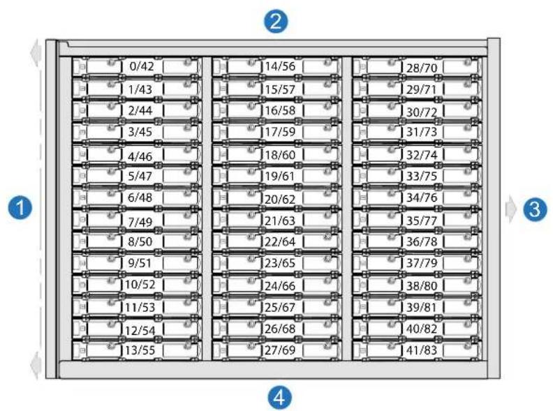
bar
| Position | Value | |---|---| | 0/42 | 14/56 | | 1/43 | 15/57 | | 2/44 | 16/58 | | 3/45 | 17/59 | | 4/46 | 18/60 | | 5/47 | 19/61 | | 6/48 | 20/62 | | 7/49 | 21/63 | | 8/50 | 22/64 | | 9/51 | 23/65 | | 10/52 | 24/66 | | 11/53 | 25/67 | | 12/54 | 26/68 | | 13/55 | 27/69 | | 28/70 | 30/72 | | 29/71 | 31/73 | | 30/72 | 32/74 | | 31/73 | 33/75 | | 34/76 | 35/77 | | 35/77 | 36/78 | | 37/79 | 38/80 | | 38/80 | 39/81 | | 40/82 | 41/83 | The chart displays a grid layout with numerical labels at the top and bottom of each cell. The numbers are explicitly labeled on each cell.1 Drawer 0/1 Front 2 Drawer 0/1 Left Side
3 Drawer 0/1 Rear (slides into chassis) 4 Drawer 0/1 Right Side
2 Open the relevant drawer per the instructions provided in Opening a 5U84 Drawer on page 189.
3 Locate the DDIC to be replaced using any of the methods listed in step 1 above.
4 Locate the latch button (Item 3) and side latch (Item 4) on the DDIC as shown in Figure 150.
Figure 150 DDIC LED
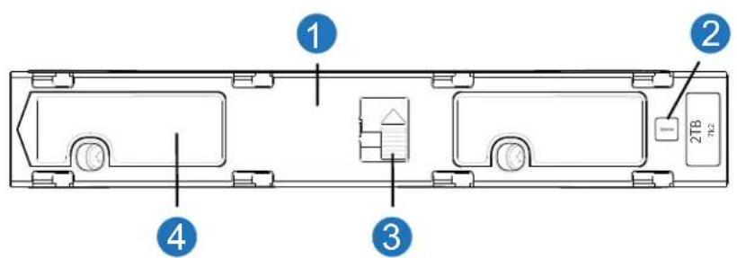
1 DDIC (longitudinal view - top face of carrier 2 Drive Fault LED
3 Latch Button (locked) 4 Side Latch
5 On the face of the DDIC:
a Push the latch button in the direction shown in Figure 151 to unlock the DDIC from its seated position in the slot.
b Then move the slide latch towards the front of the chassis to release the DDIC from the drawer. When the DDIC is released, it pops up approximately a quarter inch from the drawer.
Figure 151 Removing a DDIC-1
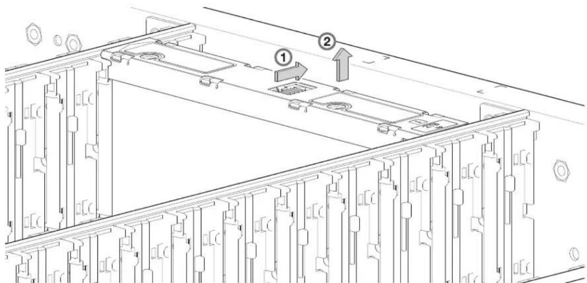
6 Pull the DDIC upwards and out of the drawer slot, Figure 152.
Figure 152 Removing a DDIC-2
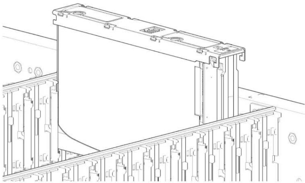
natural_image
Technical line drawing of a mechanical assembly with mounting brackets and structural supports (no text or symbols)Installing a 5U84 DDIC
IMPORTANT: Failed disks must be replaced with approved disks. Contact your service provider for details.
1 Open the relevant drawer per the instructions provided in Opening a 5U84 Drawer on page 189.
2 Align the DDIC with the target disk slot as shown in Figure 152 on page 192 and insert it into the disk slot.
3 Lower the DDIC into the disk slot.
a Push the DDIC downwards and hold it down.
b Move the side latch (Figure 153, Item 4) towards the front of the chassis to fully insert the DDIC into the drawer.
c Then, move the side latch (Figure 153, Item 4) towards the rear of the chassis to lock the DDIC into the drawer.
Figure 153 DDIC LED
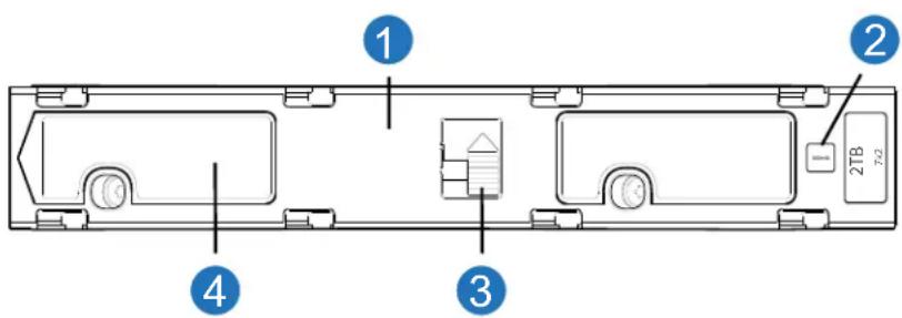
1 DDIC (longitudinal view - top face of carrier
2 Drive Fault LED
3 Latch Button (locked)
4 Side Latch
CAUTION: If the DDIC is not properly seated within the drawer, the Drive Fault LED might light and/or maybe no lights will illuminate at all. Always verify that the DDIC is properly seated within the drawer.
4 Verify the following:
a The latch button is in the locked position, as shown in Figure 153.
b The Drive Fault LED is not lit.
5 Close the drawer according to the instructions provided in Closing a 5U84 Drawer on page 190.
Populating 5U84 Drawers
General guidelines for populating a drawer with DDICs are provided at Populating Drawers with DDICs on page 53. Additional guidelines are provided for replacing drives in previously populated drawers, or populating chassis delivered with the half-populated chassis configuration option.
Preparation
Customers with multiple chassis may spread the 42 disks of an expansion package across those chassis, provided the DDICs are installed 14 at a time to completely fill empty rows. The installation pattern providing the best airflow and thermal performance is described in this section.
The drawers must be populated with DDICs in whole rows. Each drawer contains 3 rows of 14 DDICs. Rules and assumptions are listed:
- The minimum number of disks in an chassis is 14.
- The number of rows must not differ by more than 1 between the top and bottom drawers.
- The rows should be populated from front to rear of drawer.
- The drives of the expansion package must match the drives originally shipped with the 5U84 chassis. Both groups of drives must share the same model type and capacity.
NOTE: Part numbers for expansion packages are not listed because they change over time when drives ship with new firmware, or new drive models become available. Contact your account manager for part numbers.
- If the two groups of drives have different firmware, all drives must be updated with current/compatible firmware. See the QXS 12G Disk Management Utility User Guide or online help for additional information about updating firmware.
Installation Guidelines
The recommended order for partially populating drives in the 5U84 chassis optimizes the airflow through the chassis. Please reference the following illustrations:
- Front of 5U84 RAID or Expansion Chassis on page 23 shows location and indexing of drawers accessed from the chassis front panel.
- Figure 149 on page 191 shows dual-indexing of disk slots across front, middle, and back rows of a drawer.
The 5U84 ships with drawers installed in the chassis, However, to avoid shock and vibration issues during transit, the chassis does not ship with DDICs installed in the drawers. A chassis is configured with either 42 disks (half-populated) or 84 disks (fully populated) for customer delivery. If half-populated, the rows containing drives should be populated with a full complement of DDICs (no blank slots in the row). The bullet-list below identifies rows in drawers that should contain DDICs when the chassis is configured as half-populated:
- Top drawer-front row
- Top drawer–middle row
- Bottom drawer-front row
If additional drives are incrementally installed into a half-populated chassis, the DDICs must be added one row at a time (no blank slots in row) in the sequence listed:
- Bottom drawer–middle row
- Top drawer-back row
- Bottom drawer-back row
Replacing a 5U84 Bezel
The 5U84 ships with the bezels installed on the chassis drawers (Drawer 0 and Drawer 1). Refer to Figure 154. If the bezel for Drawer 0 or Drawer 1 is damaged, it must be replaced.
Comply with all ESD precautions. Refer to ESD Precautions on page 163 for additional information.
NOTE: When replacing a damaged bezel, do not open the drawer. Perform all work with the drawer closed.
Figure 154 5U84 Chassis with Bezel Installed
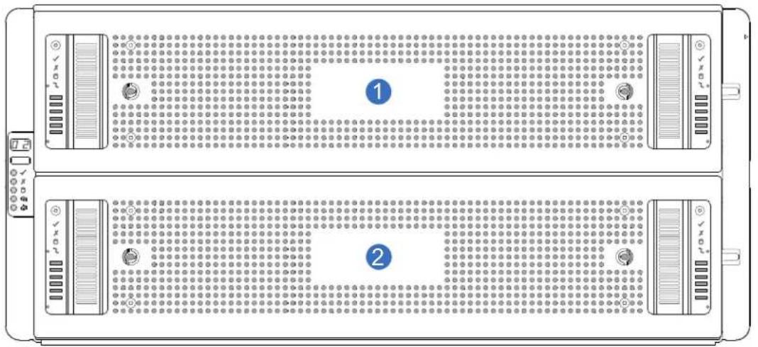
1 Drawer 0 Bezel
2 Drawer 1 Bezel
Removing a 5U84 Bezel
NOTE: Removing Drawer 0 bezel and Drawer 1 bezel is the same process. This is a representative example of removing the Drawer 1 bezel (lower drawer) from the chassis.
1 Locate the anti-tamper lock (2 Each) and the bezel screws (4 each) on the front of the 5U84 chassis drawer bezel that must be replaced (Figure 155).
Figure 155 5U84 Chassis Drawer Bezel
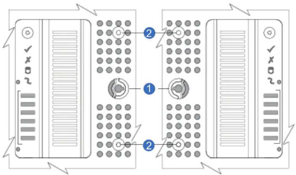
1 Anti-tamper Lock (2 Each)
2 Bezel Screws (4 each)
2 Using a T20 torque-tip driver unlock the anti-tamper locks (2 each) on the left and right side of the chassis bezel.
Figure 156 5U84 Chassis Unlock Anti-tamper Locks
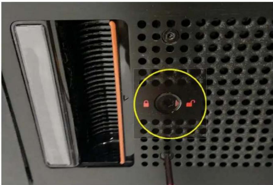
natural_image
Close-up of a black electronic device with a circular component highlighted in yellow, showing internal components and a tool inserted (no readable text or symbols)3 Using a T8 torque-tip driver remove the four bezel screws on left and right side of the bezel.
Figure 157 5U84 Chassis Bezel Screws (4 Each)
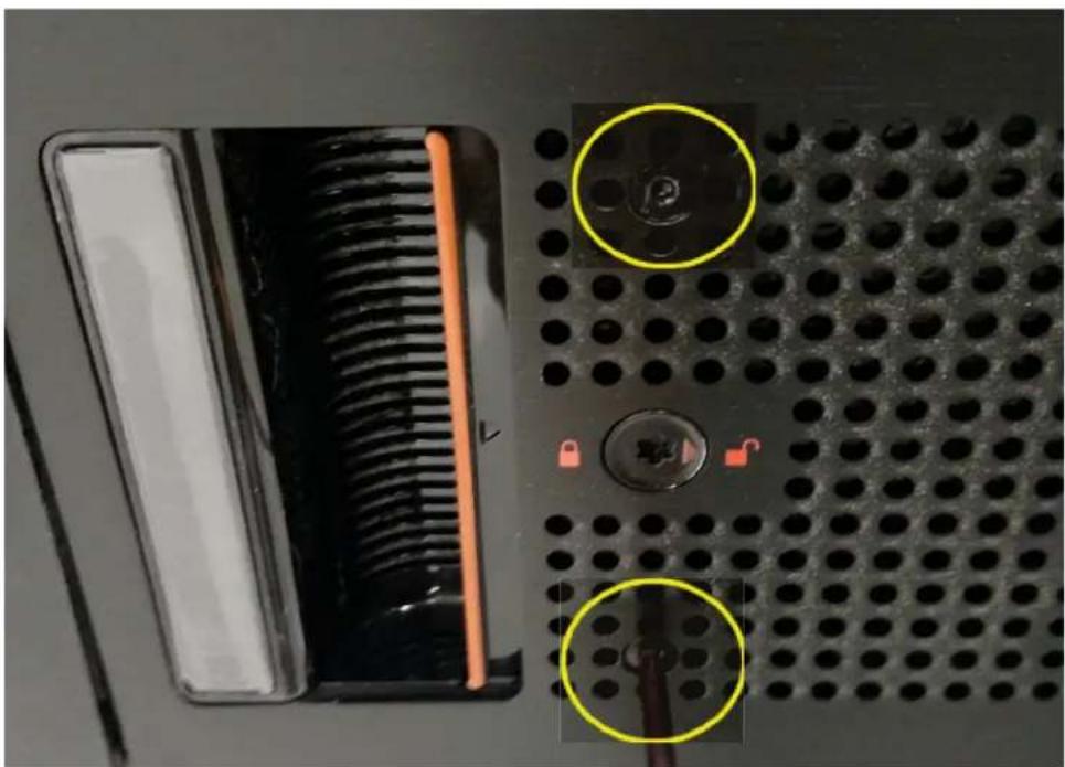
natural_image
Close-up of a computer motherboard with a grid socket, ventilation slots, and a lock (no visible text or symbols)4 Push both left and right drawer latches inward and pull out on the bezel to remove it from the 5U84 chassis.
Figure 158 5U84 Chassis Bezel Drawer Latches (2 Each)
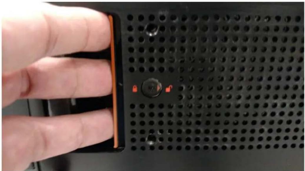
natural_image
Close-up of a hand pressing a black perforated board with two red buttons (no text or symbols visible)Figure 159 provides an illustration of the bezel removed from Drawer 1 (lower drawer).
Figure 159 5U84 Chassis Bezel Removed Drawer 1 (Lower Drawer)
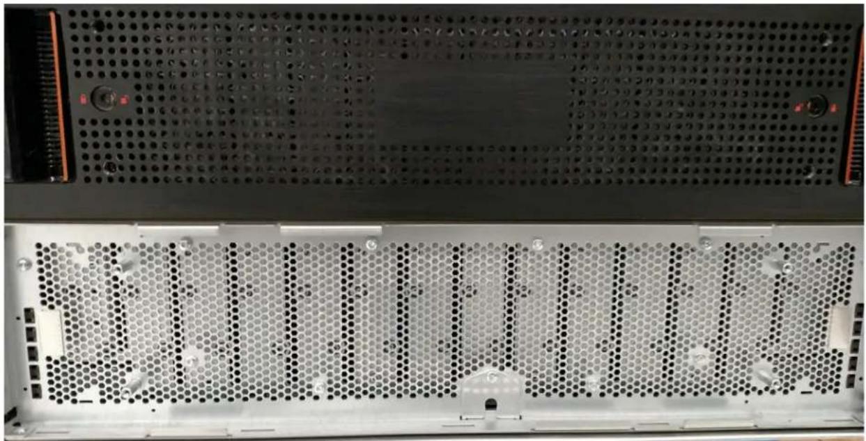
natural_image
Interior view of a computer rack with hexagonal panel and drive bays (no visible text or symbols)Installing a 5U84 Bezel
NOTE: Installing Drawer 0 bezel and Drawer 1 bezel is the same process. This is a representative example of installing the Drawer 1 bezel (lower drawer) on the chassis.
1 Locate the four screw studs on the front of the chassis drawer.
Figure 160 5U84 Chassis Bezel Removed Drawer 1 (Screw Studs)
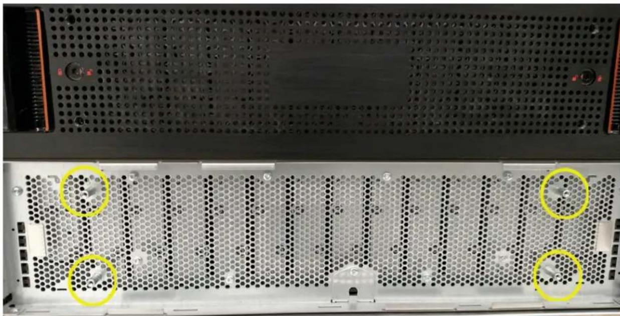
natural_image
Interior view of a server rack with hexagonal panel and mounting holes, highlighted by yellow circles (no text or symbols visible)2 Using a T20 torque-tip driver unlock the anti-tamper locks (2 each) on the left and right side of the replacement drawer bezel.
Figure 161 5U84 Drawer Unlock Anti-tamper Locks
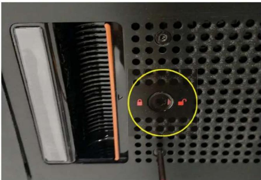
natural_image
Close-up of a computer keyboard with a highlighted socket and lock, showing no readable text or symbols.3 Push both left and right drawer latches inward and seat the bezel into the 5U84 chassis drawer slot.
Figure 162 5U84 Chassis Bezel Drawer Latches (2 Each)
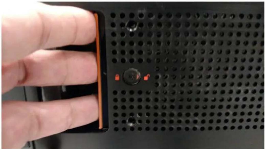
natural_image
Close-up of a finger pressing a black perforated panel with two red switches on the side (no text or symbols visible)4 Using a T8 torque-tip driver install the four bezel screws on left and right side of the bezel.
CAUTION: Do not over tighten the four bezel screws as this might damage the bezel
Figure 163 5U84 Chassis Bezel Screws (4 Each)
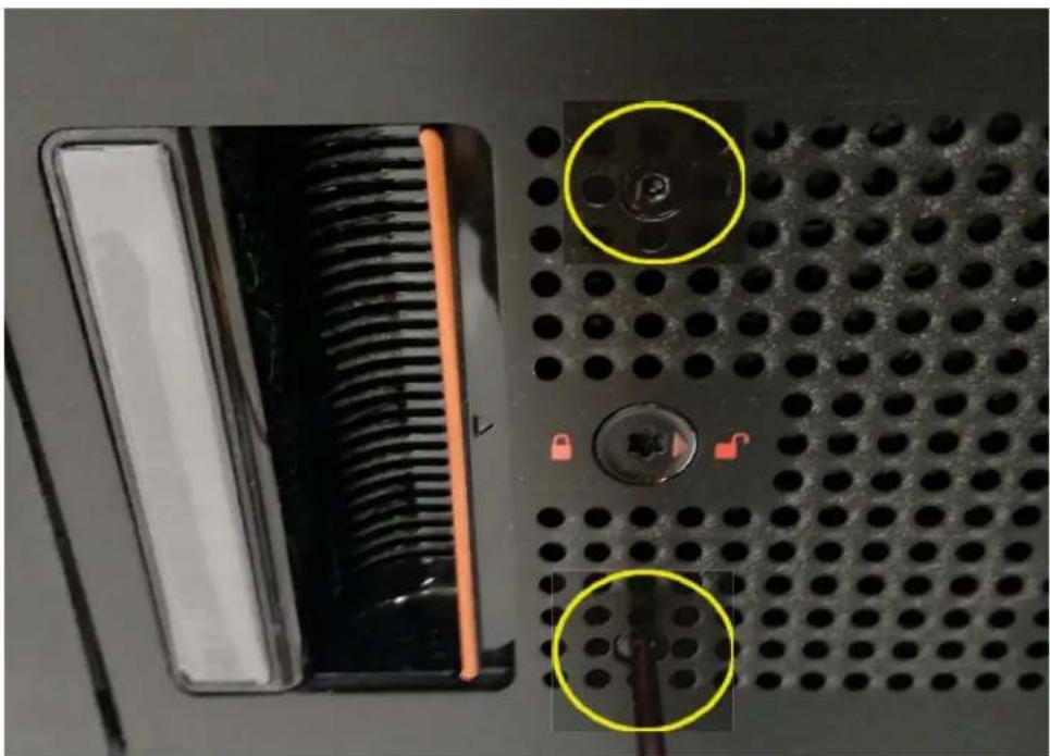
natural_image
Close-up of a black hardware component with a screw and two highlighted circular features (no text or symbols visible)5 Using a T20 torque-tip driver lock the anti-tamper locks (2 each) on the left and right side of the chassis drawer bezel.
Figure 164 5U84 Chassis Lock Anti-tamper Locks
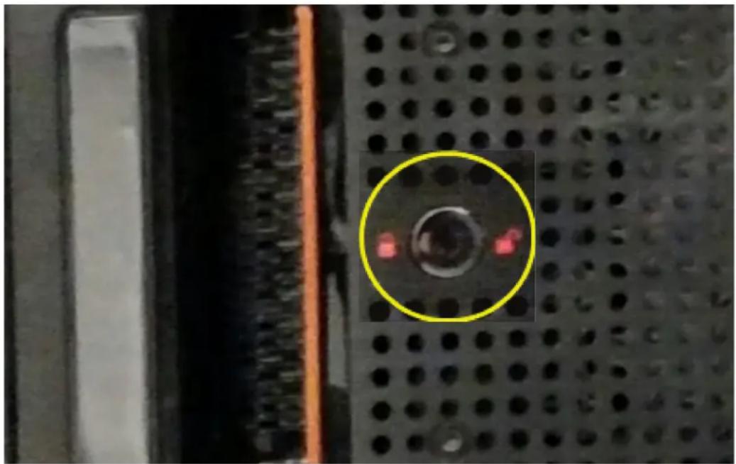
natural_image
Close-up of a black perforated surface with a circular highlight highlighting a red indicator light (no text or symbols visible)Replacing a 5U84 System PSU
Illustrations in the power supply unit module replacement procedures show rear panel views of the chassis, and PSUs are properly aligned for insertion into the PSU slots.
Comply with all ESD precautions. Refer to ESD Precautions on page 163 for additional information.
Removing a 5U84 System PSU
CAUTION: Removing a power supply unit significantly disrupts the chassis airflow. Do not remove the PSU until you have received the replacement module. It is important that all slots are filled when the chassis is in operation.
Before removing the PSU, disconnect the power from the PSU by either the mains switch (where present) or by physically removing the power source in order to ensure your system has warning of imminent power shutdown. Ensure that you correctly identify the faulty PSU before beginning the step procedure.
1 Stop all I/O from hosts to the chassis. See also Stopping I/O on page 179.
TIP: This step is not required for hot-swapping. However, it is required when replacing both PSUs at once.
2 Use management software to shut down any other system components necessary.
TIP: This step is not required for hot-swapping. However, it is required when replacing both PSUs at once.
3 Per Figure 165, verify the Power OK LED is illuminated, then switch off the faulty PSU, and disconnect the power supply cable.
Figure 165 PSU 5U84 CRU
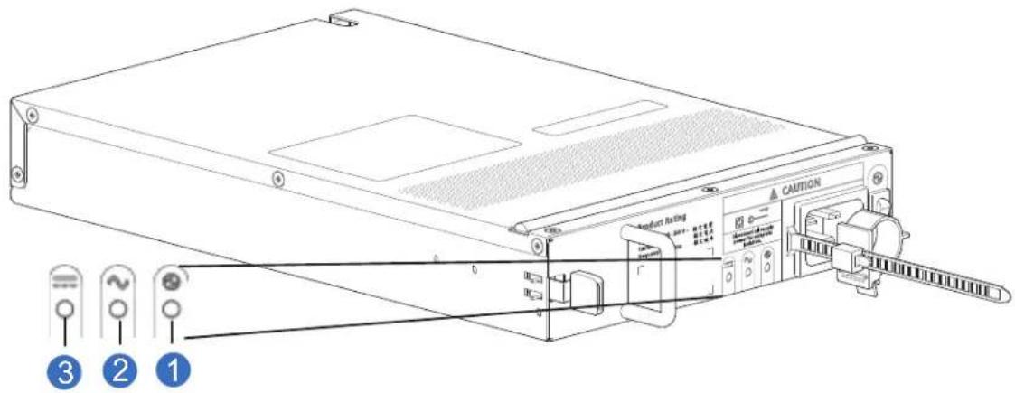
1 PSU OK LED: Green
2 AC Fail LED: Amber/blinking amber
3 PSU Fail LED: Amber/blinking amber
4 If replacing a single PSU via hot-swap, proceed to step 6.
5 If replacing both PSUs, verify that the chassis was shut down using management interfaces, and that the chassis is powered off.
6 Verify that the power cord is disconnected.
7 Refer to Figure 166 on page 201 when performing this step:
a Push the release latch to the right and hold it in place (detail No.1).
Figure 166 Removing a PSU-1
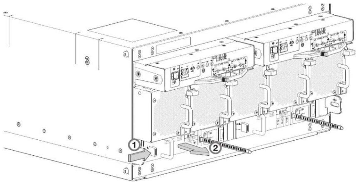
b With your other hand, grasp the handle and pull the PSU outward (detail No.2). Supporting the PSU with both hands, remove it from the chassis. See also Figure 167.
Figure 167 Removing a PSU-2
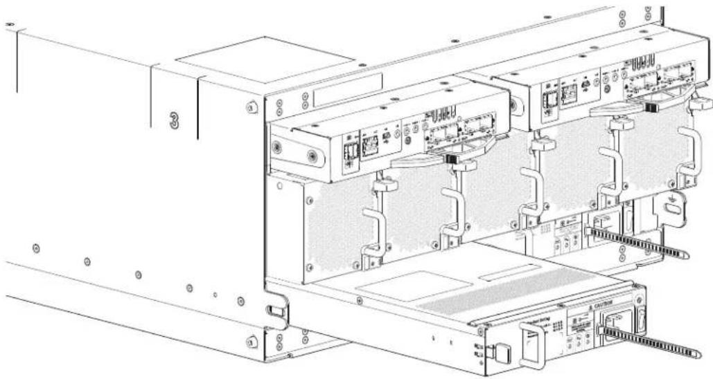
natural_image
Technical line drawing of an internal server rack with ports and connectors (no text or symbols)8 If replacing both PSUs. repeat step 5 through step 7.
IMPORTANT: The PSU slot must not be empty for more than 2 minutes while the chassis is powered.
Installing a 5U84 System PSU
1 Ensure that the PSU is switched off.
If replacing both PSUs, the chassis must be powered off via an orderly shutdown using the management interfaces.
2 Orient the PSU for insertion into the target slot on the chassis rear panel, as shown in Figure 167.
3 Slide the PSU into the slot until the latch clicks home.
4 Connect the AC power cord.
5 Move the PSU power switch to the On position.
6 Wait for the Power OK LED on the newly inserted PSU to illuminate green. See also Figure 165 on page 201.
- If the Power OK LED does not illuminate, verify that the PSU is properly inserted and seated in the slot.
- If properly seated, the module may be defective. Check the disk management utility (GUI) and the event logs for more information.
- Using the management interfaces (the disk management utility (GUI) or CLI), determine if the health of the new PSU is OK. Verify that the Power OK LED is green, and that the Ops panel states show no amber module faults.
7 If replacing both PSUs, repeat step 1 through step 6.
Replacing a 5U84 System Fan
Illustrations in the fans replacement procedures show rear panel views of the chassis, and fans are properly aligned for insertion into the fan slots.
Comply with all ESD precautions. Refer to ESD Precautions on page 163 for additional information.
Removing a 5U84 System Fan
CAUTION: Removing an fan significantly disrupts the chassis airflow. Do not remove the fan until you have received the replacement module. It is important that all slots are filled when the chassis is in operation.
1 Identify the fan module to be removed. If the fan module has failed, the Fan Fault LED will illuminate amber. See also Figure 168.
Figure 168 Fan 5U84 CRU
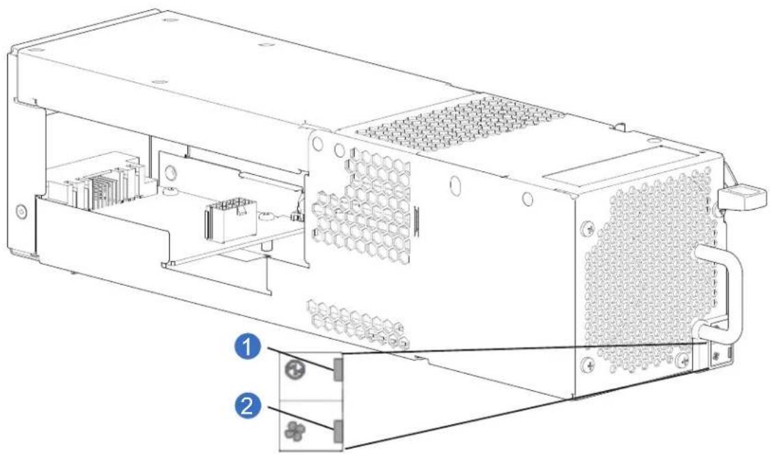
natural_image
Technical line drawing of an electronic device chassis with internal components and connectors (no text or symbols)1 Fan OK LED: Green
2 Fan Fault LED: Amber/blinking amber
Note: If any of the fan LEDs are illuminated amber, a module fault condition or failure has occurred.
2 Refer to Figure 169 when performing this step:
a Push the release latch down and hold it in place (detail No.1).
Figure 169 Removing Fan-1
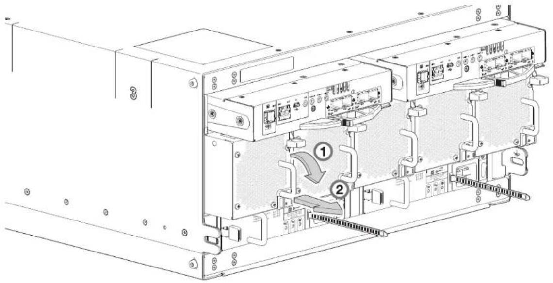
b With your other hand, grasp the handle and pull the fan outward (Figure 169, detail No.2). Supporting the fan with both hands, remove it from the chassis. See also Figure 170.
Figure 170 Removing Fan-2
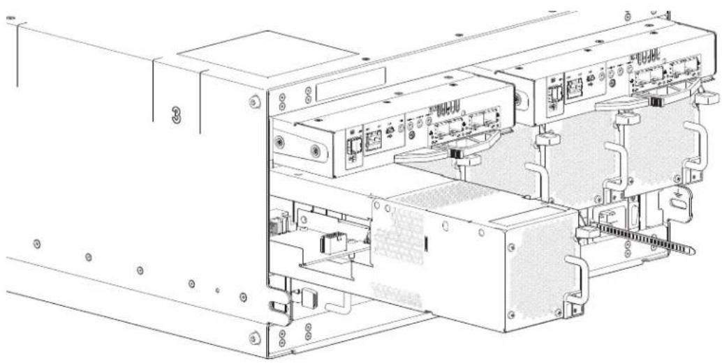
natural_image
Technical line drawing of an internal computer or server unit with ports and connectors (no text or symbols visible)IMPORTANT: The fan slot must not be empty for more than 2 minutes while the chassis is powered.
Installing a 5U84 System Fan
1 You can hotswap the replacement of a single fan; however, if replacing multiple fans, the chassis must be powered off via an orderly shutdown using the management interfaces.
2 Orient the fan for insertion into the target slot on the chassis rear panel, as shown in Figure 170 on page 204.
3 Slide the fan into the slot until the latch clicks home.
The chassis should automatically detect and make use of the new module.
4 Wait for the Module OK LED on the newly inserted fan to illuminate green. See also Figure 168 on page 203.
- If the Module OK LED does not illuminate, verify that the fan is properly inserted and seated in the slot.
- If properly seated, the module may be defective. Check the disk management utility (GUI) and the event logs for more information.
- Using the management interfaces (the disk management utility (GUI) or CLI), determine if the health of the new fan is OK. Verify that the Module OK LED is green, and that the Ops panel states show no amber module faults.
5 If replacing multiple fans, repeat step 1 through step 3.
Replacing a QXS-484 12G RAID Controller or Expansion IOM
The QXS-412 12G, QXS-424 12G, and QXS-484 12G systems support a common set of RAID controllers in the RAID chassis, and a common expansion IOM in the expansion chassis, within supported 2U and 5U chassis configurations.
• Figure 171 provides an illustration of the CNC (FC/iSCSI Controller).
• Figure 172 provides an illustration of the Expansion IOM.
Figure 171 CNC (FC/iSCSI Controller)
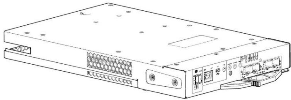
natural_image
Line drawing of a server rack with ports, connectors, and ventilation slots (no text or labels)Figure 172 Expansion IOM
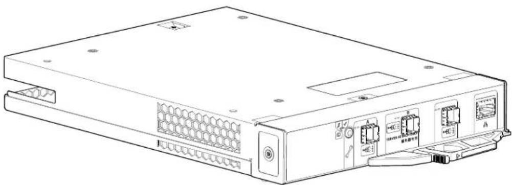
natural_image
Line drawing of a server rack unit with ports and connectors (no text or symbols)Be mindful of the intricacies associated with RAID controllers and/or expansion IOMs before engaging in replacement. Key considerations pertaining to controllers and/or expansion IOM replacement in 2U chassis apply equally to 5U chassis. Please familiarize yourself with these topics before replacing a controller or expansion IOM in the 5U84 chassis:
IMPORTANT: The QXS-412 12G, QXS-424 12G, and QXS-484 12G systems support dual-controller configuration only. If a partner controller fails, the storage system will fail over and run on a single controller module until the redundancy is restored. A controller module must be installed in each slot to ensure sufficient air flow through the chassis during operation.
• Before You Begin on page 178
- Configuring Partner Firmware Update on page 178
• Verifying Component Failure on page 179
- Stopping I/O on page 179
• Shutting Down a Controller Module on page 180
Removing a 5U84 RAID Controller or Expansion IOM
IMPORTANT: Considerations for removing controller modules:
- In a dual-controller environment, you may hot-swap a single controller module in an operational chassis, provided you first shut down the faulty controller using the disk management utility (GUI) or the CLI.
- In a dual-controller environment—if replacing both controller modules—you must adhere to the instructions provided in Before You Begin on page 178.
- Do not remove a faulty module unless its replacement is on-hand. All modules must be in place when the system is in operation.
Comply with all ESD precautions. Refer to ESD Precautions on page 163 for additional information.
Illustrations in the controller module replacement procedures show rear panel views of the chassis, and the controllers/expansion IOMs are properly aligned for insertion into the applicable slots.
1 Verify that you have successfully shut down the controller module using the disk management utility (GUI) or the CLI.
2 Locate the chassis whose UID LED (Ops panel on chassis left front ear) is illuminated, and within the chassis, locate the controller module whose OK to Remove LED is blue (rear panel).
3 Disconnect any cables connected to the controller or expansion IOM.
Label each cable to facilitate re-connection to the replacement controller or expansion IOM.
4 Grasp the module latch between the thumb and forefinger, and squeeze the flange and handle together to release the latch handle from its docking member (detail No.1), and swing the latch out to release the controller or expansion IOM from its seated position (detail No.2) as shown in Figure 173 and Figure 174 on page 207.
Figure 173 Controller or Expansion IOM Latch Operation

5 Grip the latch handle and ease the controller or expansion IOM outward from its installed position as shown in detail No.3 in Figure 174.
Figure 174 Removing a Controller or Expansion IOM-1
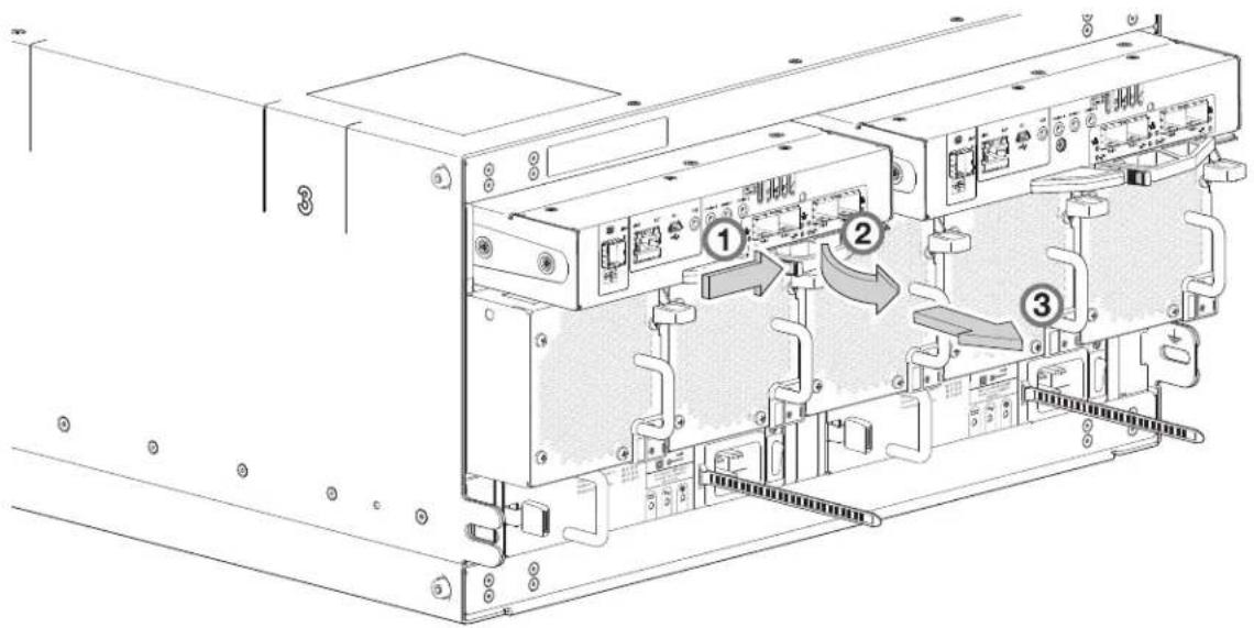
NOTE: Figure 174 and Figure 175 show a 4-port FC/iSCSI controller. However, the procedure applies to all controller and expansion IOMs used in 5U84 chassis. They all use the same latch mechanism, but feature different face plate geometry as shown in Figure 171 on page 205.
6 Place both hands on the controller or expansion IOM, and pull it straight out of the chassis.
Figure 175 Removing a Controller or Expansion IOM-2
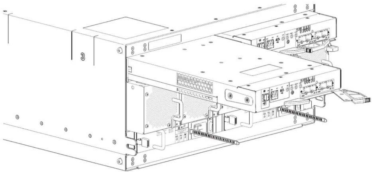
natural_image
Technical line drawing of an internal computer drive bay with ports and connectors (no text or symbols)IMPORTANT: The SBB expansion IOM slot must not be empty for more than two minutes while the chassis is powered on.
Installing a 5U84 RAID Controller or Expansion IOM
Comply with all ESD precautions. Refer to ESD Precautions on page 163 for additional information.
CAUTION: If passive copper cables are connected, the cable must not have a connection to a common ground/earth point.
NOTE: When performing the following procedure, refer to Figure 175.
1 Examine the controller or expansion IOM for damage, and closely inspect the interface connector. Do not install if the pins are bent.
2 Grasp the controller or expansion IOM using both hands, and with the latch in the open position, orient the module and align it for insertion into the target slot.
3 Ensuring that the controller or expansion IOM is level, slide it into the chassis as far as it will go.
A controller module that is only partially seated will prevent optimal performance of the RAID chassis. Verify that the controller module is fully seated before continuing.
4 Set the module in position by manually closing the latch. See detail No.2, followed by No.1 in Figure 173 on page 206.
You should hear a click as the latch handle engages and secures the controller or expansion IOM to its connector on the back of the midplane.
5 Reconnect the cables.
6 See Verifying Component Operation on page 183.
NOTE: In a dual-controller system in which PFU is enabled, when you update the firmware on one controller, the system automatically updates the partner controller.
Replacing a 5U84 Chassis
The RAID chassis or expansion chassis replacement procedure replaces a damaged 5U chassis CRU. The procedure includes removing all CRU modules from a damaged chassis and installing them into a replacement chassis.
IMPORTANT: The CRUs for the QXS-484 12G systems using the 5U84 chassis are described in 5U84 Chassis CRU Replacement on page 188.
Whether your product is configured as a RAID chassis or an expansion chassis, a fully functional replacement chassis requires the successful removal and installation of the following components:
- All power and data cables
- All DDICs from chassis drawers
- Two power supply unit modules (both AC)
- Five fan modules
- Two controllers or expansion IOMs of the same model type
This procedure references the CRU component procedures described elsewhere in this chapter.
CAUTION: Do not remove the chassis until you have received the replacement chassis.
Comply with all ESD precautions. Refer to ESD Precautions on page 163 for additional information.
1 Schedule down time that will allow for shutdown; sixty minutes of replacement work; and restart.
2 Verify the existence of a known/good backup of the system.
3 Record system settings for future use and label all cables.
4 Prepare a suitable static-protected work environment to accommodate chassis replacement.
Verifying Component Failure
The RAID chassis or expansion chassis CRU includes the chassis metal housing, the module runner system, the integrated Ops panel, chassis drawers for holding DDICs, and the assembled/installed midplane, sideplane, and baseplane PCBs that connect various components within the chassis. See Figure 176 and Figure 177 for a pictorial view of the 5U84.
Figure 176 provides a front view of the 5U84-drive system.
Figure 176 5U84-Drive System-Front View
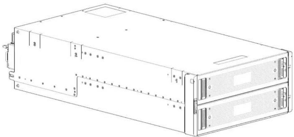
natural_image
Line drawing of a server rack unit with two drive bays and ventilation slots (no text or labels)Figure 177 provides a rear view of the 5U84-drive system. The 5U84 RAID chassis has dual-controllers (4-port FC/iSCSI model shown) installed.
Figure 177 5U84-Drive System-Rear View
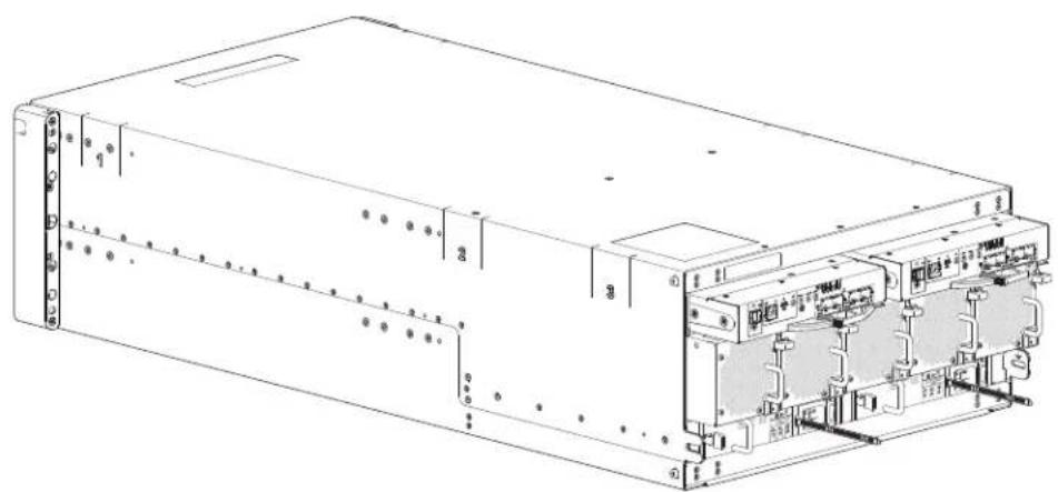
natural_image
Technical line drawing of an electronic device chassis with labeled ports and internal components (no readable text or symbols)The 5U84 chassis CRU replaces a chassis that has been damaged, or whose midplane has been damaged. Often, a damaged midplane will appear as though a RAID controller has failed. If you replace a controller module and it does not remedy the fault, you may need to replace the RAID chassis.
You can observe chassis health (front panel and rear panel) using management interfaces to verify chassis/component failure or chassis/component operation. See also Using Management Interfaces on page 188.
Preparing to Remove a Damaged 5U84 Chassis
Because you are removing and replacing an entire chassis, neither the hot-swap capability that applies to replacing individual redundant CRUs in an operational chassis, nor the hot-add of a drive chassis to an operational storage system, apply to this procedure.
1 Stop all I/O from hosts to the system. See also Stopping I/O on page 179.
2 Shut down the controllers. See also Shutting Down a Controller Module on page 180.
3 Power off the system – RAID chassis first, expansion chassis next: see Powering On/Powering Off on page 105.
Table 47 Replacing a 5U Chassis and Installing CRUs
| To accomplish this sequential process: See the following procedures: | |||
| 1 Facing the front of the 5U chassis, access the drawers and remove DDICs (label each DDIC) from the damaged chassis and place them in a static-protected work area nearby. ^1 & 4 | a | Opening a 5U84 Drawer on page 189 | |
| b | Removing a 5U84 DDIC on page 190 | ||
| c | Closing a 5U84 Drawer on page 190 | ||
| 2 Facing the rear of the 5U chassis, remove the power and data cables. | Removing a Damaged 5U84 Chassis from the Rack on page 211 | ||
| 3 Remove the damaged storage chassis from the rack. ^2 | Removing a Damaged 5U84 Chassis from the Rack on page 211 | ||
| 4 Remove the two PSUs from the damaged chassis rear panel, and install them in the replacement chassis. | a | See PSU related cautions and tips in Removing a 5U84 System PSU, page 200. | |
| b | Removing a 5U84 System PSU, page 200 | ||
| c | Installing a 5U84 System PSU, page 202 | ||
| 5 Remove the five fans from the damaged chassis rear panel, and install them in the replacement chassis. | a | Removing a 5U84 System Fan, page 203 | |
| b | Installing a 5U84 System Fan, page 204 | ||
| 6 Remove the two controllers or expansion IOMs from the damaged chassis rear panel, and install them in the replacement chassis. ^3 | a | Replacing a QXS-484 12G RAID Controller or Expansion IOM, page 205 | |
| b | Removing a 5U84 RAID Controller or Expansion IOM, page 206 | ||
| c | Installing a 5U84 RAID Controller or Expansion IOM, page 208 | ||
| d | Verifying Component Operation, page 187 | ||
| 7 Install the replacement storage chassis in the rack. | Installing a Replacement 5U84 Chassis into the Rack, page 212 | ||
Table 47 Replacing a 5U Chassis and Installing CRUs
| To accomplish this sequential process: | See the following procedures: | ||
| 8 Facing the front of the 5U chassis, access the drawers and install DDICs retrieved from the damaged chassis into the replacement chassis.4 | a | Full Disk Encryption (FDE) on page 65 | |
| b | Accessing 5U84 Drawers on page 189 | ||
| c | Populating 5U84 Drawers on page 193 | ||
| d | Installing a 5U84 DDIC, page 192 | ||
| 9 | Complete the chassis replacement process. | a | Completing the Process on page 187 |
| b | Verifying Component Operation, page 187 | ||
Table46 Notes:
^1 If you temporarily stack the drives before installing them, insert static dissipative foam between the drive modules.
^2 Fully configured 5U84 chassis can weigh up to 128 kg (282 lb) and require a suitable mechanical lift.
^3 Within the replacement chassis, each controller or expansion IOM must be reinstalled into the same controller or expansion IOM slot from which it was extracted from the damaged chassis (0A > 0A and 0B > 0B, respectively). For FC/iSCSI controllers, the SFPs installed in the CNC ports need not be removed. For SFP replacement, see SFP Option for CNC Ports on page 229.
^4 Within the replacement chassis, reinstall each drive or drive blank into the same drive slot from which it was removed from the damaged chassis. To ensure optimal cooling throughout the chassis, dummy drive carriers must be fitted to all unused drive slots.
Removing a Damaged 5U84 Chassis from the Rack
This section provides a procedure for removing a damaged 5U chassis from its rack location.
CAUTION: It is recommended that all DDICs be removed from the drawers before removing the chassis from the rack. A suitable mechanical lift is required to move a high-density 5U84 chassis.
1 Disconnect the power cables and data cables between devices as needed:
a Between the cascaded chassis.
b Between the controller and peripheral SAN devices.
c Between the controller and the host.
NOTE: Label the cables to facilitate reconnection of the storage devices.
2 Position a suitable mechanical lift to receive the chassis.
3 Remove the retaining screws that secure the front and rear of the chassis to the rack and rails.
NOTE: Do not remove the ear components from the failed chassis: integrated ear components and covers are provided with the replacement chassis CRU.
4 Maintaining a level position, carefully slide the chassis from the rack.
5 Place the chassis on a static-protected work surface near the replacement chassis, with the removed DDICs and rackmount screws.
Installing a Replacement 5U84 Chassis into the Rack
CAUTION: If any licenses other an Q-Tier (virtualization) were installed on the system, after chassis swap, customer must obtain a new license set tied to the new OEM serial number. Refer to the QXS 12G CLI Reference Guide to obtain the license set. Also, differentiate the TLA serial number from the OEM serial number.
This section provides a procedure for installing the replacement chassis in its rack location.
IMPORTANT: Refer to Installing 5U Chassis, page 64 when installing the chassis into the rack.
IMPORTANT: Install the chassis into the rack before re-inserting the DDICs. A suitable mechanical lift is required to move the chassis.
1 Support the bottom of the chassis. Carefully lift/align the chassis and while maintaining a level position for the chassis, slide it into the rack.
2 Using the appropriate mounting hardware, secure the chassis to the rack.
3 Using the applicable retaining screws, secure the front and rear of the chassis to the rack and rails.

natural_image
Abstract pattern of blue squares arranged in a grid on white background (no text or symbols)Chapter 7
Technical Specifications
This chapter provides the following information:
• QXS 2U/5U Chassis Dimensions
• QXS 2U/5U Chassis Weights
• QXS 2U/5U Environmental Requirements
• QXS 2U/5U PSU Specifications
QXS 2U/5U Chassis Dimensions
This section contains the following information:
• QXS 2U Chassis Dimensions
• QXS 5U Chassis Dimensions
QXS 2U Chassis Dimensions
Table 48 provides the 2U chassis dimensions.
Table 48 QXS 2U Chassis Dimensions
| Specification Metric Unit Imperial Unit | ||
| Overall chassis height (2U) 87.9 mm 3.46 in | ||
| Width across mounting flange (located on front of chassis) 483 mm 19.01 in | ||
| Width across body of chassis 443 mm 17.44 in | ||
| Depth from face of mounting flange to back of chassis body 576.8 mm | 22.71 in | |
| Depth from face of mounting flange to rearmost chassis extremity 602 | 9 mm 23.74 in | |
| Depth from face of Ops panel to rearmost chassis extremity | 629.6 mm 24.79 in | |
| Note 1: The 2U24 chassis uses 2.5" SFF disks. | ||
| Note 2: The 2U12 chassis uses 3.5" LFF disks. | ||
QXS 5U Chassis Dimensions
Table 49 provides the 5U chassis dimensions.
Table 49 QXS 5U Chassis Dimensions
| Specification Metric Unit Imperial Unit | ||
| Overall chassis height (5U) 222.3 mm 8.75 in | ||
| Width across mounting flange (located on front of chassis) 483 mm 19.01 in | ||
| Width across body of chassis 444.5 mm 17.50 in | ||
| Depth from face of mounting flange to back of chassis body 892.2 mm | 35.12 in | |
| Depth from face of mounting flange to rearmost chassis extremity 974.7 mm 38.31in | ||
| Depth from face of Ops panel to rearmost chassis extremity 981 mm 38.62 in | ||
| Note: The 5U84 uses 3.5" LFF disks in the DDIC carrier. It can also use 2.5" SFF disks with 3.5" adapter in the DDIC. | ||
QXS 2U/5U Chassis Weights
Table 50 provides the chassis weights for the 2U12, 2U24, and 5U84 chassis.
Table 50 QXS 2U/5U Chassis Weights
| CRU/Component | 2U12 (kg/lb) | 2U24 (kg/lb) | 5U84 (kg/lb) |
| Storage chassis (empty) | 4.8/10.56 | 4.8/10.56 | 64/141 |
| Disk drive carrier | 0.9/1.98 | 0.3/0.66 | 0.8/1.8 |
| Dummy disk drive carrier (air management sled) | 0.05/0.11 | 0.05/0.11 | - |
| 2U Power Supply Unit (PSU) | 3.5/7.7 | 3.5/7.7 | - |
| 5U Power Supply Unit (PSU) | - | - | 2.7/6.0 |
| 5U Fan | - | - | 1.4/3.0 |
| Controller (module in RAID chassis) | 2.6/5.8 | 2.6/5.8 | 2.6/5.8 |
| Expansion IOM (module in expansion chassis) | 1.5/3.3 | 1.5/3.3 | 1.5/3.3 |
| RAID chassis (fully populated with modules: maximum weight) | 32/71 30/66 135/298 | ||
| Expansion chassis (fully populated with modules: maximum weight) | 28/62 25/55 130/287 | ||
| Note 1: Weights shown are nominal, and subject to variances. | |||
| Note 2: 2U rail kits add between 2.8 kg (6.2 lb) and 3.4 kg (7.4 lb) to the aggregate chassis weight. 5U rail kits add significantly more weight. | |||
| Note 3: Weights may vary due to different power supplies, controllers/expansion IOMs, and differing calibrations between scales. | |||
| Note 4: Weights may vary due to actual number and type of drives (SAS or SSD) and air management modules installed. | |||
QXS 2U/5U Environmental Requirements
This section contains the following information:
• QXS 2U/5U Ambient Temperature and Humidity Requirements
• QXS 2U/5U Additional Environmental Requirements
QXS 2U/5U Ambient Temperature and Humidity Requirements
Table 51 provides the 2U/5U ambient temperature and humidity requirements.
Table 51 QXS 2U/5U Ambient Temperature and Humidity Requirements
| Specification Temperature | Range Relative Humidity | Maximum Wet Bulb | |
| Operating RAID Chassis: 5°C to 35°C(41°F to 95°F)Expansion Chassis: 5°C to 40°C (41°F to 104°F) | 20% to 80%non-condensing | 28°C | |
| No-operating (shipping) -40°C to +70°C (-40°F to +158°F) | 5% to 100%non-precipitating | 29°C | |
QXS 2U/5U Additional Environmental Requirements
Table 52 provides the 2U/5U additional environmental requirements.
Table 52 QXS 2U/5U Additional Environmental Requirements
| Specification Measurement/Description | |
| Airflow System must be operated with low pressure rear exhaust installation. Back pressure created by rack doors and obstacles not to exceed 5Pa (0.5 mm H_2O ) | |
| Altitude (operating) | 2U chassis: 0 to 3,000 meters (0 to 10,000 feet) Maximum operating temperature is de-rated by 5°C above 2,133 meters (7,000 feet) |
| 5U chassis: -100 to 3,000 meters (-330 to 10,000 feet) Maximum operating temperature is de-rated by 1°C above 900 meters (3,000 feet) | |
| Altitude (non-operating) | -100 to 12,192 meters (-330 to 40,000 feet) |
| Shock (operating) | 5.0 g, 10 ms, 1⁄2 sine pulses, Y-axis |
| Shock (non-operating) | 2U chassis: 30.0 g, 10 ms, 1⁄2 sine pulses |
| 5U chassis: 30.0 g, 10 ms, 1⁄2 sine pulses (Z-axis); 20.0 g, 10 ms, 1⁄2 sine pulses (X- and Y-axes) | |
| Vibration (operating) | 0.21 Gr_ms 5 Hz to 500 Hz random |
| Vibration (non-operating) | 1.04 G_rms 2 Hz to 200 Hz random |
| Vibration (relocation) | 0.3 G_rms 2 Hz to 200 Hz 0.4 decades per minute |
| Acoustics Operating sound power | |
| Operating and mounting: 19" rack mount (2 EIA units; 5 EIA units) | |
| • Rack rails | To fit 800 mm depth racks compliant with the SSI server rack specification |
| • Rack characteristics | Back pressure not exceeding 5Pa (~0.5 mm H2O) |
QXS 2U/5U PSU Specifications
This section contains the following information:
• QXS 2U PSU (580W) Specifications
• QXS 5U PSU (2114W) Specifications
QXS 2U PSU (580W) Specifications
Table 53 provides the 2U PSU (580W) specifications.
Table 53 QXS 2U PSU (580W) Specifications
| Specification Measurement/Description | ||
| Dimensions (size) 84.3 mm high x 104.5 mm wide x 340.8 mm long:• X-axis length: 104.5 mm (4.11 in)• Y-axis length: 84.3 mm (3.32 in)• Z-axis length: 340.8 mm (37.03) | ||
| Maximum output power | 580W | |
| Voltage range | 100–200 VAC rated | |
| Frequency | 50-60 Hz | |
| Voltage range selection | Auto-ranging: 90–264 VAC, 47–63 Hz | |
| Power factor correction | ^3 95% @ nominal input voltage | |
| Efficiency | 115 VAC/60 Hz | 230 VAC/50 Hz |
| >80% @ 10% load>87% @ 20% load>90% @ 50% load>87% @ 100% load>85% @ surge | >80% @ 10% load>88% @ 20% load>92% @ 50% load>88% @ 100% load>85% @ surge | |
| Harmonics | Meets EN61000-3-2 | |
| Output | +5 V @ 42A, +12 V @ 38A, +5 V standby voltage @ 2.7A | |
Table 53 (continued) QXS 2U PSU (580W) Specifications
| Specification Measurement/Description | |
| Operating temperature 0 to 57°C (32°F to +135°F) | |
| Hot pluggable Yes | |
| Switches and LEDs AC mains switch and four status indicator LEDs | |
| Chassis cooling Dual axial cooling fans with variable fan speed control | |
QXS 5U PSU (2114W) Specifications
Table 54 provides the 5U PSU (2114W) specifications.
Table 54 QXS 5U PSU (2114W) Specifications
| Specification Measurement/Description | |
| Maximum output power 2214W max | maximum continuous output power at high line voltage |
| Voltage +12 V at 183 A (2,196 W) | +5 V standby voltage at 2.7 A |
| Voltage range 200–240 VAC rated | |
| Frequency | 50-60 Hz |
| Power factor correction | >/= 95% @ 100% load |
| Efficiency | 82% @ 10% load90% @ 20% load94% @ 50% load91% @ 100% load |
| Holdup time | 5 ms from ACOKn high to rails out of regulation (see SBB v2 specification) |
| Mains inlet connector | IEC60320 C20 with cable retention |
| Weight | 3 kg (6.6 lb) |
| Cooling fans | 2 stacked fans: 80x80x38mm |

natural_image
Abstract pattern of blue squares arranged in a grid on white background (no text or symbols)Chapter 8
Standards and Regulations
This chapter provides the following information:
• International Standards
• Potential for Radio Frequency Interference
• European Regulations
- Safety Compliance
• EMC Compliance
- AC Power Cords
• Recycling of Waste Electrical and Electronic Equipment (WEEE)
International Standards
The QXS-412 12G, QXS-424 12G, and QXS-484 12G systems comply with the requirements of the following agencies and standards:
- CE to EN 60950-1
• CB report to IEC 60950-1
• UL & cUL to UL 60950-1 second edition
Potential for Radio Frequency Interference
USA Federal Communications Commission (FCC)
Notice
This equipment has been tested and found to comply with the limits for a class A digital device, pursuant to Part 15 of the FCC rules. These limits are designed to provide reasonable protection against harmful interference when the equipment is operated in a commercial environment. This equipment generates, uses, and can radiate radio frequency energy, and if not installed and used in accordance with the instruction manual, may cause harmful interference to radio communications. Operation of this equipment in a residential area is likely to cause harmful interference, in which case the user will be required to correct the interference at his or her expense.
Properly shielded and grounded cables and connectors must be used in order to meet FCC emission limits. The supplier is not responsible for any radio or television interference caused by using other than recommended cables and connectors or by unauthorized changes or modifications to this equipment. Unauthorized changes or modifications could void the user's authority to operate the equipment.
This device complies with Part 15 of the FCC Rules. Operation is subject to the following two conditions: (1) this device may not cause harmful interference, and (2) this device must accept any interference received, including interference that may cause undesired operation.
European Regulations
This equipment complies with European Regulations EN 55022 Class A: Limits and Methods of Measurement of Radio Disturbance Characteristics of Information Technology Equipment and EN50082-1: Generic Immunity.
Safety Compliance
Table 55 provides safety compliance specifications.
Table 55 Safety Compliance Specifications
| Item | Compliance |
| System product type approval UL/cUL/CE | |
| Safety Compliance UL 60950-1 second edition | |
EMC Compliance
Table 56 provides EMC compliance specifications.
Table 56 EMC Compliance Specifications
| Item | Compliance |
| Conducted emissions limit levels CFR47 Part 15B Class A | R47 Part 15B Class A |
| EN55022 Class A | |
| CISPR Class A | |
| Radiated emissions limit levels CFR47 Part 15B Class A | 47 Part 15B Class A |
| EN55022 Class A | |
| CISPR Class A | |
| Harmonics and flicker EN61000-3-2/3 | |
| Immunity limit levels EN55024 |
AC Power Cords
Table 57 provides the AC power cord specifications.
Table 57 AC Power Cord Specifications
| 1 | United States of America-Must be NRTL Listed (National Recognized Test Laboratory - e.g., UL): | ||
| Chassis form factor 2U12/2U24 5U84 | |||
| Cord type SV or SVT, 18 | AWG minimum, 3 conductor, 2.0M max length | SJT or SVT, 12 AWG minimum, 3 conductor | |
| Plug (AC source) NEMA | 5-15P grounding-type attachment plug rated 120V 10A | IEC 320, C-20, 250V, 20A | |
| or or | |||
| IEC 320, C-14, 250V, 10A A suitable plug rated 250V, 20A | |||
| Socket | IEC 320, C-13, 250V, 10A | IEC 320, C-19, 250V, 20A | |
| 2 Europe and others-General requirements: | |||
IMPORTANT: The plug and the complete power cable assembly must meet the standards appropriate to the country, and must have safety approvals acceptable in that country.
Recycling of Waste Electrical and Electronic Equipment (WEEE)
At the end of the product's life, all scrap/waste electrical and electronic equipment should be recycled in accordance with national regulations applicable to the handling of hazardous/toxic electrical and electronic waste materials.
Please contact your supplier for a copy of the Recycling Procedures applicable to your country.
IMPORTANT: Observe all applicable safety precautions detailed in the preceding chapters (weight restrictions, handling batteries and lasers, etc.) when dismantling and disposing of this equipment.

natural_image
Abstract pattern of blue squares arranged in a grid on white background (no text or symbols)Chapter 9
USB Device Connection
This chapter provides the following information:
- Rear Panel USB Ports
• Device Driver/Special Operation Mode
• Using CLI Port and Cable/Known Issues in Windows
NOTE: This chapter covers the QXS-312 12G, QXS-324 12G, QXS-412 12G, QXS-424 12G, and QXS-484 12G systems.
Rear Panel USB Ports
The QXS-312 12G, QXS-324 12G, QXS-412 12G, QXS-424 12G, and QXS-484 12G system controllers contain a USB (Universal Serial Bus) Device interface pertaining to the Management Controller (MC). The Device interface is accessed via a port on the controller module face plate. This chapter describes the USB Type B port labeled CLI, which enables direct connection between a management computer and the controller, using the command-line interface and appropriate cable.
Figure 178 provides the location of the USB device connection (CLI port) on the back of the controller.
Figure 178 USB Device Connection (CLI port)
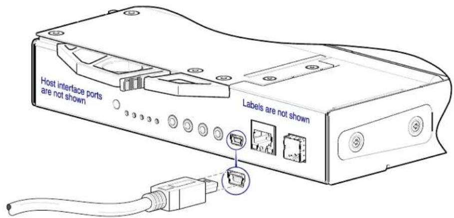
The QXS-312 12G, QXS-324 12G, QXS-412 12G, QXS-424 12G, and QXS-484 12G system controllers feature a USB CLI port used to cable directly to the controller and initially set IP addresses, or perform other configuration tasks.
- The USB CLI port employs a mini-USB Type B form factor, and requires a specific cable and additional support, so that a server or other computer running a Linux or Windows operating system can recognize the RAID chassis as a connected device.
- Without this support, the computer might not recognize that a new device is connected, or might not be able to communicate with it.
For Linux computers, no new driver files are needed, but a Linux configuration file must be created or modified. See also Setting Parameters for Device Driver on page 226.
For Windows computers a special device driver file, gserial.inf, must be downloaded from a CD or web site, and installed on the computer that will be cabled directly to the controller's CLI port. See also Microsoft Windows on page 225.
Emulated Serial Port
Once attached to the controller module, the management computer should detect a new USB device. Using the Emulated Serial Port interface, the QXS-312 12G, QXS-324 12G, QXS-412 12G, QXS-424 12G, and QXS-484 12G system controller presents a single serial port using a customer vendor ID and product ID. Effective presentation of the emulated serial port assumes the management computer previously had terminal emulator installed. See also Supported Host Applications on page 224. Serial port configuration is unnecessary.
IMPORTANT: Certain operating systems require a device driver or special mode of operation to enable proper functioning of the USB CLI port. See also Device Driver/Special Operation Mode on page 225.
Supported Host Applications
QXS-312 12G, QXS-324 12G, QXS-412 12G, QXS-424 12G, and QXS-484 12G system controllers support the following applications to facilitate connection.
Table 58 Supported Terminal Emulator Application
| Application Operating System | |
| HyperTerminl, TeraTerm, PuTTY | Microsoft Windows (all versions) |
| Minicom Linux (all versions) | |
| Solaris | |
| HP-UX | |
Command-line Interface
Once the management computer detects connection to the USB-capable device, the Management Controller awaits input of characters from the host computer via the command-line. To see the command-line prompt, you must press Enter. The MC provides direct access to the CLI.
NOTE: Directly cabling to the CLI port is an out-of-band connection, because it communicates outside of the data paths used to transfer information from a computer or network to the RAID chassis (controllers).
Device Driver/Special Operation Mode
Certain operating systems require a device driver or special mode of operation. Product and vendor identification information required for such setup is provided below.
Table 59 USB Vendor and Product Identification Codes
| USB Identification Code Type Code | |
| USB Vendor ID 0x210c | |
| USB Product ID 0xa4a7 | |
Microsoft Windows
Microsoft Windows operating systems provide a USB serial port driver. However, the USB driver requires details for connecting to QXS-312 12G, QXS-324 12G, QXS-412 12G, QXS-424 12G, and QXS-484 12G systems RAID chassis. The QXS systems provides a device driver for use in the Windows environment. The USB device driver and installation instructions are available via a download.
Obtaining the Software Download
If using Windows 10/Server 2016, the operating system provides a native USB serial driver that supports the controller module's USB CLI port. However, if using an older version of Windows, you should download and install the USB device driver, using the procedure below.
1 Verify that the management computer has Internet access.
2 For customer support, contact Quantum support.
3 Follow the instructions accompanying the device drive topic fro Microsoft Windows.
NOTE: More information about this product is available on the Service and Support website at http://www.quantum.com/ServiceandSupport/Index.aspx. The Service and Support Website contains a collection of information, including answers to frequently asked questions (FAQs). You can also access software, firmware, and drivers through this site.
For further assistance, or if training is desired, contact the Quantum Customer Support Center:
| United States 1-800-284-5101 (toll free) | +1-720-249-5700 |
| EMEA +800-7826-8888 (toll free) | +49-6131-3241-1164 |
| APAC +800-7826-8887 (toll free) | +603-7953-3010 |
For worldwide support:
http://www.quantum.com/ServiceandSupport/Index.aspx
Setting Parameters for Device Driver
1 Enter the following command:
modprobe usbserial vendor=0x210c product=0xa4a7 use_acm=1
2 Press Enter to execute the command.
The Linux device driver is loaded with the parameters required to recognize the controllers.
NOTE: Optionally, this information can be incorporated into the /etc/modules.conf file.
Using CLI Port and Cable/Known Issues in Windows
When using the CLI port and cable for setting network port IP addresses, be aware of the following known issues on Microsoft Windows platforms.
Problem
On Windows operating systems, the USB CLI port may encounter issues preventing the terminal emulator from reconnecting to storage after the Management Controller (MC) restarts or the USB cable is unplugged and reconnected.
Workaround
Follow these steps when using the mini-USB cable and USB Type B CLI port to communicate out-of-band between the host and controller module for setting network port IP addresses.
Create New Connection
To create a new connection or open an existing connection (HyperTerminal):
1 From the Windows Control Panel, select Device Manager.
2 Connect using the USB COM port and Detect Carrier Loss option.
a Select Connect To > Connect using: > pick a COM port from the list.
b Select the Detect Carrier Loss check box.
The Device Manager page should show "Ports (COM & LPT)" with an entry entitled "Disk Array USB Port (COMn)"—where n is your system's COM port number.
3 Set network port IP addresses using the CLI (see Setting Network Port IP Addresses Using CLI Port and Cable on page 94).
Restore a Hung Connection
To restore a hung connection when the MC is restarted (any supported terminal emulator):
1 If the connection hangs, disconnect and quit the terminal emulator program.
a Using Device Manager, locate the COM n port assigned to the Disk Array Port.
b Right-click on the hung Disk Array USB Port (COMn), and select Disable.
c Wait for the port to disable.
2 Right-click on the previously hung—now disabled—Disk Array USB Port (COM _n ), and select Enable.
3 Start the terminal emulator and connect to the COM port.
4 Set network port IP addresses using the CLI (see Setting Network Port IP Addresses Using CLI Port and Cable on page 94).
NOTE: When using Windows 10/Server 2016 with PuTTY, the XON/XOFF setting must be disabled, or the COM port will not open.

natural_image
Abstract pattern of blue squares arranged in a grid on white background (no text or symbols)Chapter 10
SFP Option for CNC Ports
This chapter provides the following information:
- Locate SFP Transceivers
• Install SFP Transceiver - Verify Component Operation
NOTE: This chapter covers the QXS-312 12G, QXS-324 12G, QXS-412 12G, QXS-424 12G, and QXS-484 12G systems.
Locate SFP Transceivers
Locate the qualified SFP options for your FC/iSCSI controller canister within your product ship kit. The SFP transceiver (SFP) should look similar to the generic SFP shown in Figure 179. When installing an SFP, refer to Figure 179.
Figure 179 Installing a FC/iSCSI SFP in the QXS Controller
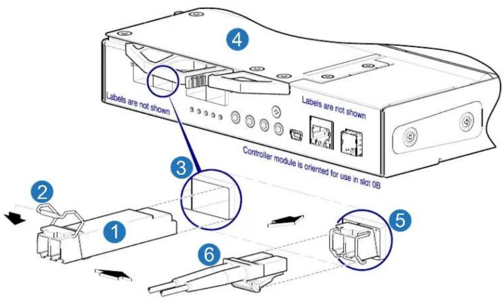
1 SFP (orient for insertion to CNC port) 2 SFP Lock/Unlock Actuator
3 Target CNC Port 4 Controller in RAID Chassis
5 SFP Seated in CNC Port 6 Fiber Optic Interface Cable (Host)
CNC Ports/SFP Configuration
The QXS-312 12G, QXS-324 12G, QXS-412 12G, QXS-424 12G, and QXS-484 12G systems ship with the CNC ports configured for FC. If you are to install iSCSI SFPs, you must configure the ports for iSCSI.
NOTE: It is best to reconfigure the CNS ports before installing the iSCSI SFPs within the controller. You must use the QXS 12G CLI Reference Guide to reconfigure the CNC ports (not the disk management utility, GUI).
Connecting CNC Ports to iSCSI Hosts
To configure the CNC ports for iSCSI hosts, use the QXS 12G CLI Reference Guide. Refer to the following sections within the guide for assistance:
- set host-parameters
- Sets controller host-port parameters for communication with attached hosts.
- Configure CNC ports as FC or iSCSI.
- Also see the following commands:
- restart mc
- restart sc
- set host-port-mode
- set iscsi-parameters
- show ports
Install SFP Transceiver
For each target CNC port, perform the following procedure to install an SFP. Refer to the Figure 179 when performing the steps.
NOTE: Comply with all ESD precautions. Refer to ESD Precautions on page 163 for additional information.
1 Orient the SFP for the target CNC port and canister position, and align it for insertion.
Depending upon whether the SFP is installed into controller A or B in 2U chassis, it will either install right-side up, or upside down.
2 If the SFP has a plug, remove it before installing the transceiver. Retain the plug.
3 Flip the actuator open (sweep up or down) according to the SFP position and alignment for canister slot 0A (top) or 0B (bottom).
The actuator on your SFP option may look slightly different than the one shown, and it may not open to a sweep greater than 90^ (as shown in the figure above).
4 Slide the SFP into the target CNC port until it locks securely into place.
5 Flip the actuator closed (sweep up or down) according to its position in canister slot 0A or 0B. The installed SFP should look similar to the position shown in the right detail view above.
6 When ready to attach to the host, obtain and connect a qualified fiber-optic interface cable into the duplex jack at the end of the SFP connector.
Verify Component Operation
View the CNC port Link Status/Link Activity LED on the controller face plate. A green LED indicates that the port is connected and the link is up:
• For FC SFPs, see Figure 47 on page 42.
• For 10GbE iSCSI SFPs, see Figure 47 on page 42.
• For 1Gb iSCSI SFPs, see Figure 48 on page 44
NOTE: To remove an external SFP connector, perform the installation steps in reverse order relative to what is described in Install SFP Transceiver on page 230.
- QXS 12G Hardware Installation and Maintenance Guide
- Contents
- About This Guide ix
- Safety Guidelines....1
- System Overview....5
- Operation....105
- Troubleshoot/Problem Solving 115
- Standards and Regulations 219
- USB Device Connection 223
- SFP Option for CNC Ports 229
- About This Guide
- Introduction
- Chassis User Interfaces
- CNC Ports Used for Host Connection
- Intended audience
- Prerequisites
- Related Documentation
- Document conventions and symbols
- Chapter 1
- Safety Guidelines
- Safe Handling of Equipment
- Operation of the QXS 12G Systems
- IMPORTANT:
- Electrical Safety
- Rack System Safety Precautions
- Chapter 2
- System Overview
- Chassis Configurations
- CompactFlash
- Supercapacitor Pack
- Front and Rear Views of QXS 12G Systems
- 2U12-Drive System
- 2U12-Drive System Serial Number Label Location
- 2U24-Drive System
- 2U24-Drive System Serial Number Label Location
- 5U84-Drive System
- 5U84-Drive System Serial Number Label Location
- Chassis Variants
- 2U Chassis Core Product
- 2U12-Drive Chassis Front View
- 2U24-Drive Chassis Front View
- QXS-312 12G and QXS-324 12G RAID Chassis Rear View (2-Host Port Controllers)
- QXS-312 12G and QXS-324 12G RAID Chassis (CNC Controllers and 2FC/iSCSI ports)
- CNC FC/iSCSI Controller
- QXS-412 12G, QXS-424 12G, and QXS-484 12G RAID Chassis Rear View (4-Host Port Controllers)
- RAID Chassis (CNC Controllers and 4 FC/iSCSI ports)
- 2U12-Drive/2U24-Drive Expansion Chassis Rear View
- Expansion Chassis
- Expansion Chassis IOM
- Power Supply Unit (PSU)
- 2U RAID/Expansion Chassis
- Front of 2U12 RAID or Expansion Chassis
- Front of 2U24 RAID or Expansion Chassis
- NOTE:
- 5U Chassis Core Product
- 5U Chassis Front View
- 5U Chassis Drive Slots View
- 5U84 RAID Chassis (Rear View/Two CNC Controllers)
- 5U84 Expansion Chassis (Rear View)
- Fans
- 5U Chassis
- 5U Chassis Drawers
- Safety features
- Locking Drawer
- 2U Operator's (Ops) Panel
- 2U12 Chassis Ops Panel
- 2U24 Chassis Ops Panel
- 2U12 and 2U24 Ops Panel Functions
- LED Status
- System Power On/Standby LED (green/amber)
- Module Fault LED (amber)
- Location LED (blue)
- Unit Identification Display
- Thermal sensor
- 5U Chassis Ops Panel
- Chassis Ops Panel Location
- Ops Panel Functions
- Logical Status LED (amber)
- Drawer Fault LEDs (amber)
- PSUs - 2U CRU
- PSU Features
- Multiple PSUs
- System Airflow
- PSU - 5U CRU
- Fan - 5U CRU
- Fan OK LED: Green
- Fan Fault LED: Amber/blinking amber
- RAID Controller and Expansion IOMs
- 12Gb/s Controller LEDs
- CNC Controller (2-Port FC and 10GbE SFPs) and LED
- LED Description Definition
- CNC iSCSI Controller (2-Port 1Gb RJ-45 SFPs) and LED
- CNC Controller (4-Port FC and 10GbE SFPs) and LED
- CNC iSCSI Controller (4-Port 1Gb RJ-45 SFPs) and LED
- Cache Overview and Status LED Details
- Cache Overview
- Power On/Off Behavior
- Cache Status Behavior
- Controller Failure/Single-Controller Operational
- 12Gb/s Expansion IOM
- Drive Modules
- Drive Carrier Module in 2U Chassis
- Populating 2U12 Chassis with Drives
- Populating 2U24 Chassis with Drives
- LFF 3.5" Drive Carrier Module (SAS Drive)
- SFF 2.5" Drive Carrier Module (SAS Drive)
- Drive Status Indicators
- Drive Blanks
- DDIC in 5U chassis
- DDIC with 3.5" Drive
- DDIC with Adapter and 2.5" Drive
- Populating Drawers with DDICs
- Chassis Management
- Management Interfaces
- Chapter 3
- Installation
- Installation Checklist
- Planning for Installation
- Preparing for Installation
- NOTE: Chassis configurations:
- CAUTION: Lifting chassis:
- Preparing Site and Host Server
- Unpacking Chassis
- Required Tools
- Requirements for rackmount installation
- Rackmount rail kit
- Installing 2U Chassis
- Installing 5U Chassis
- Full Disk Encryption (FDE)
- Federal Information Processing Standards (FIPS)
- Connecting RAID Chassis and Expansion Chassis
- Cable Requirements for Expansion Chassis
- Reverse Cabling/Straight-through Cabling for 2U Systems
- Reverse Cabling for 5U84 Systems
- Straight-Through Cabling for 5U84 Systems
- Reverse Cabling for 2U to 5U84 Systems
- Straight-Through Cabling for 2U to 5U84 Systems
- Power Cord Connection
- CAUTION: Power connection concerns:
- Testing Chassis Connections
- Grounding Checks
- Host System Requirements
- Cabling Considerations
- CNC Technology
- Fibre Channel (FC) Protocol
- 1Gb iSCSI Protocol
- Host Connection
- Fibre Channel Host Connection
- 10GbE iSCSI Host Connection
- 1Gb iSCSI Host Connection
- Connecting Direct Attach Configurations
- 2U12/2U24 (4-Host Ports) One Server/One HBA/Dual Path
- 2U12/2U24 (2-Host Ports) One Server/One HBA/Dual Path
- 5U84 One Server/One HBA/Dual Path
- 2U12/2U24 (4-Host Ports) Two Servers/One HBA Per Server/Dual Path
- 2U12/2U24 (2-Host Ports) Two Servers/One HBA Per Server/Dual Path
- 5U84 Two Servers/One HBA Per Server/Dual Path
- 2U12/2U24 Four Servers/One HBA Per Server/Dual Path
- 5U84 Four Servers/One HBA Per Server/Dual Path
- Switch Attach
- 2U12/2U24 (4-Host Ports) Two Servers/Two Switches
- 2U12/2U24 (2-Host Ports) Two Servers/Two Switches
- 5U84 Two Servers/Two Switches
- 2U12/2U24 Four Servers/Multiple Switches/SAN Fabric
- 5U84 Four Servers/Multiple Switches/SAN Fabric
- Connecting Management Host to Network
- Updating Firmware
- Important Firmware Notes
- Verifying Firmware
- Obtaining IP Values and System Settings
- Updating System Settings using the Disk Management Utility (DMU) GUI
- Setting Network Port IP Addresses Using DHCP
- Setting Network Port IP Addresses Using CLI Port and Cable
- set network-parameters ip 192.168.0.11 netmask 255.255.255.0 gateway
- Change CNC Port Mode
- Set CNC Port Mode to iSCSI
- Connecting Two Storage Systems to Replicate Volumes
- Cabling for Replication
- Host Ports and Replication
- Multiple Servers/Single Same Network
- Connecting Two 2U Storage Systems (4-Host Ports) for Replication
- Connecting Two 2U Storage Systems (2-Host Ports) for Replication
- Connecting Two 5U Storage Systems for Replication
- Multiple Servers/Different Networks
- Connecting Two 2U Systems (4-Host Ports) for Replication (Multiple Servers/Switches)
- Connecting Two 2U Systems (2-Host Ports) for Replication (Multiple Servers/Switches)
- Connecting Two 5U Systems for Replication (Multiple Servers/Switches)
- Multiple Servers/Different Networks/Multiple Switches
- Connecting Two 2U Systems (4-Host Ports) for Replication (Multiple Servers/Switches/Locations)
- Connecting Two 2U Systems (2-Host Ports) for Replication (Multiple Servers/Switches/Locations)
- Chapter 4
- Operation
- Before You Begin
- Powering On/Powering Off
- Guidelines
- Powering On the 2U12 and/or 2U24 System
- Powering On the 2U12 and/or 2U24 Expansion Chassis
- Powering On the 2U12 and/or 2U24 RAID Chassis
- Powering Off the 2U12 and/or 2U24 System
- Powering On the 5U84 System
- Powering On the 5U84 Expansion Chassis
- Powering On the 5U84 RAID Chassis
- Powering Off the 5U84 System
- Operator's (Ops) Panel LEDs
- Unit Identification Number
- Software/SES
- Disk Drive LEDs
- Disk Modules Used in 2U Chassis
- DDICs Used in 5U Chassis
- Accessing Disk Management Utility (GUI)
- Getting Started
- Configuring and Provisioning the Storage System
- Chapter 5
- Troubleshoot/Problem Solving
- Overview
- Initial Start-Up Problems
- Faulty Power Cords
- Computer Does Not Recognize the Storage System
- LEDs
- 2U Chassis LEDs
- 2U Chassis 580W PSU LEDs
- 2U Chassis Ops Panel LEDs
- Actions:
- 2U Chassis Drive LEDs
- QXS-312/324 12G Chassis RAID Chassis Controller LEDs
- QXS-412/424/484 12G Chassis RAID Chassis Controller LEDs
- 2U Chassis Expansion IOM LEDs
- 5U Chassis LEDs
- 5U Chassis PSU LEDs
- 5U Chassis Fan Module LEDs
- 5U Chassis Ops Panel LEDs
- 5U Chassis Drawer LEDs
- 5U Chassis DDIC LEDs
- 5U RAID Controller LEDs
- 5U Expansion IOM LEDs
- Temperature Sensors
- Audible Alarm
- Table Notes
- Troubleshooting 2U Chassis
- PSU Faults
- Thermal Monitoring and Control
- Thermal Alarm
- Troubleshooting 5U Chassis
- Thermal Considerations
- USB CLI Port Connection
- Fault Isolation methodology
- Basic Steps
- Options Available for Performing Basic Steps
- Use the Disk Management Utility (GUI)
- Use the CLI
- Monitor Event Notification
- View the Chassis LEDs
- Performing Basic Steps
- Gather Fault Information
- Determine Where the Fault is Occurring
- Review the Event Logs
- Isolate the Fault
- If the Chassis Does Not Initialize
- Correcting Chassis IDs
- Host I/O
- Dealing with Hardware Faults
- Isolating a Host-Side Connection Fault
- Host-Side Connection Troubleshooting Featuring CNC Ports
- Isolating a Controller Module Expansion Port Connection Fault
- Isolating Replication Faults
- Replication Setup and Verification
- Diagnostic Steps for Replication Setup
- Using the Replication Feature
- Creating a Replication Set
- Replicating a Volume
- Checking for a Successful Replication
- Continuous Operation During Replacement
- Firmware Updates
- Customer-Replaceable Units
- 2U 2-/4-Port Controller RAID Chassis Matrix
- Table33 Notes
- 5U 4-Port Controller RAID Chassis Matrix
- Table34 Notes
- 2U12 RAID Chassis/Expansion Chassis CRUs
- 2U12 RAID Chassis CRUS (Front)
- 2U12 QXS-312 12G RAID Chassis CRUS (Rear)
- 2U12 QXS-412 12G RAID Chassis CRUS (Rear)
- 2U12 Expansion Chassis CRUs (Front)
- 2U12 Expansion Chassis CRUs (Rear)
- 2U24 RAID Chassis/Expansion Chassis CRUs
- 2U24 RAID Chassis CRUS (Front)
- 2U24 QXS-324 12G RAID Chassis CRUS (Rear)
- 2U24 QXS-424 12G RAID Chassis CRUS (Rear)
- 2U24 Expansion Chassis CRUs (Front)
- 2U24 Expansion Chassis CRUs (Rear)
- 5U84 RAID Chassis/Expansion Chassis CRUs
- 5U84 RAID Chassis/Expansion Chassis (Front View)
- 5U84 RAID Chassis/Expansion Chassis Drawer (Drives/CRUs)
- 5U84 RAID Chassis CRUs (Rear View/Two CNC Controllers)
- 5U84 Expansion Chassis CRUs (Rear View)
- RAID Controllers and Expansion IOMs for QXS 12G Systems
- CNC Controller for RAID Chassis (2-Host Ports)
- CNC Controller for RAID Chassis (4-Host Ports)
- Expansion IOM for Expansion Chassis
- Chapter 6
- Module Remove and Replace
- ESD Precautions
- Preventing ESD
- Grounding Methods to Prevent ESD
- 2U Chassis CRU Replacement
- Removing a 2U Bezel
- Installing a 2U Bezel
- Replacing a 2U PSU
- Removing a 2U PSU
- Installing a 2U PSU
- Replacing a 2U Drive Carrier Module
- Removing a 2U 3.5" LFF Drive Carrier Module
- Installing a 2U 3.5" LFF Drive Carrier Module
- Using the Anti-Tamper Locks
- Removing a 2U 2.5" SFF Drive Carrier Module
- Installing a 2U 2.5" SFF Drive Carrier Module
- Replacing a 2U Drive Blank
- Replacing a 2U RAID Controller or an Expansion IOM
- Configuring Partner Firmware Update
- Verifying Component Failure
- Stopping I/O
- Shutting Down a Controller Module
- Using the Disk Management Utility (GUI)
- Using the CLI
- Removing a 2U RAID Controller or an Expansion IOM
- Installing a 2U RAID Controller or an Expansion IOM
- Verifying Component Operation
- RAID Controller
- Expansion IOM
- Replacing a 2U Storage Chassis
- Preparing to Remove a Damaged 2U Chassis
- Table46 Notes:
- Removing a Damaged 2U Chassis from the Rack
- Installing the Replacement 2U Chassis in the Rack
- Completing the Process
- Using LEDs
- Using Management Interfaces
- 5U84 Chassis CRU Replacement
- Accessing 5U84 Drawers
- Opening a 5U84 Drawer
- Closing a 5U84 Drawer
- Replacing a 5U84 DDIC
- Removing a 5U84 DDIC
- Installing a 5U84 DDIC
- Populating 5U84 Drawers
- Preparation
- Installation Guidelines
- Replacing a 5U84 Bezel
- Removing a 5U84 Bezel
- Installing a 5U84 Bezel
- Replacing a 5U84 System PSU
- Removing a 5U84 System PSU
- Installing a 5U84 System PSU
- Replacing a 5U84 System Fan
- Removing a 5U84 System Fan
- Installing a 5U84 System Fan
- Replacing a QXS-484 12G RAID Controller or Expansion IOM
- Removing a 5U84 RAID Controller or Expansion IOM
- Installing a 5U84 RAID Controller or Expansion IOM
- Replacing a 5U84 Chassis
- Preparing to Remove a Damaged 5U84 Chassis
- Removing a Damaged 5U84 Chassis from the Rack
- Installing a Replacement 5U84 Chassis into the Rack
- Chapter 7
- Technical Specifications
- QXS 2U/5U Chassis Dimensions
- QXS 2U Chassis Dimensions
- QXS 5U Chassis Dimensions
- QXS 2U/5U Chassis Weights
- QXS 2U/5U Environmental Requirements
- QXS 2U/5U Ambient Temperature and Humidity Requirements
- QXS 2U/5U Additional Environmental Requirements
- QXS 2U/5U PSU Specifications
- QXS 2U PSU (580W) Specifications
- QXS 5U PSU (2114W) Specifications
- Chapter 8
- Standards and Regulations
- International Standards
- Potential for Radio Frequency Interference
- Notice
- European Regulations
- Safety Compliance
- EMC Compliance
- AC Power Cords
- Recycling of Waste Electrical and Electronic Equipment (WEEE)
- Chapter 9
- USB Device Connection
- Rear Panel USB Ports
- Emulated Serial Port
- Supported Host Applications
- Command-line Interface
- Device Driver/Special Operation Mode
- Microsoft Windows
- Obtaining the Software Download
- Setting Parameters for Device Driver
- Using CLI Port and Cable/Known Issues in Windows
- Problem
- Workaround
- Create New Connection
- Restore a Hung Connection
- Chapter 10
- SFP Option for CNC Ports
- Locate SFP Transceivers
- CNC Ports/SFP Configuration
- Connecting CNC Ports to iSCSI Hosts
- Install SFP Transceiver
- Verify Component Operation
Brand : QUANTUM
Model : Xcellis QXS-424
Category : Disk array