
QSW-1208-8C - Network switch QNAP - Free user manual and instructions
Find the device manual for free QSW-1208-8C QNAP in PDF.


| Product Type | Managed Layer 2 Network Switch |
| Ports | 8 x 10G SFP+ (fiber) + 4 x 10GBASE-T (RJ45) + 1 x 1G SFP+ (combo) |
| Switching Capacity | 240 Gbps |
| MAC Address Table | 32K entries |
| Dimensions (W x D x H) | 285 x 185 x 44 mm (11.22 x 7.28 x 1.73 in) |
| Weight | 1.54 kg (3.4 lbs) |
| Power Supply | Internal, 100-240V AC, 50-60 Hz, 45W max |
| Fan | 1 x 40mm fan (temperature-controlled) |
| Management | Web GUI, SNMP, CLI (via console port) |
| VLAN Support | 802.1Q VLAN, up to 256 VLANs |
| Link Aggregation | LACP, up to 8 groups |
| Quality of Service (QoS) | 802.1p, DSCP, 8 priority queues |
| Rack Mountable | Yes (1U, mounting kit included) |
| Operating Temperature | 0°C to 40°C (32°F to 104°F) |
| Certifications | CE, FCC, RoHS |
Frequently Asked Questions - QSW-1208-8C QNAP
User questions about QSW-1208-8C QNAP
0 question about this device. Answer the ones you know or ask your own.
Ask a new question about this device
Download the instructions for your Network switch in PDF format for free! Find your manual QSW-1208-8C - QNAP and take your electronic device back in hand. On this page are published all the documents necessary for the use of your device. QSW-1208-8C by QNAP.
USER MANUAL QSW-1208-8C QNAP
natural_image
Simple line icon of an open box with an upward arrow, no text or symbols presentPackage Contents

natural_image
Simple line drawing of a rectangular box with lid and front panel (no text or symbols)QSW-1208-8C
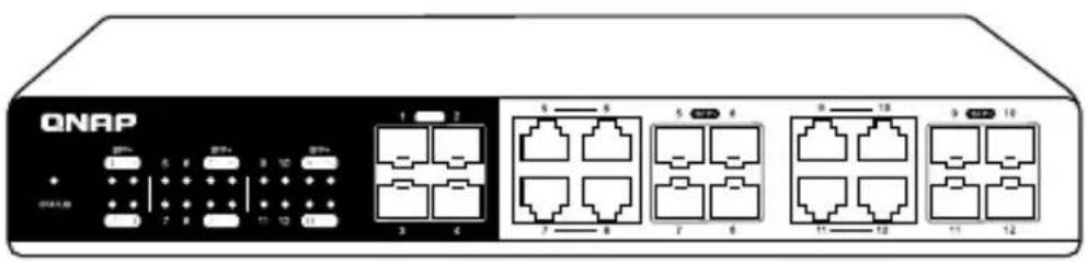
Rackmount brackets Power cordFoot pads Bracket screws

natural_image
Pure electrical circuit components without any text or symbolsHardware Overview
Front Panel Ports
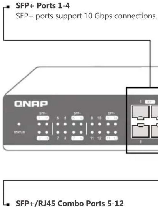
Each port number has two types: SFP+ and RJ45. Users may select either one to connect.
Front Panel LED
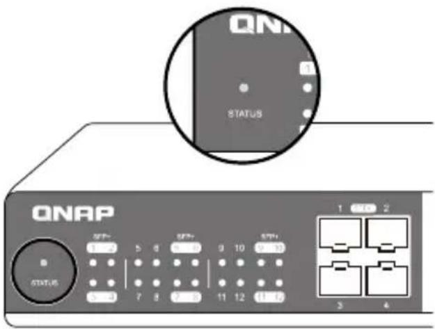
Status
- Off: System down.
- Green System is ready for use. Flashing indicates bootup in progress.
- Amber: System warning, e.g. high temperature or fan error.

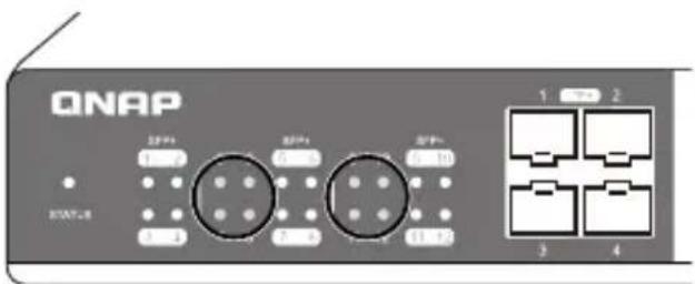
SFP+ Ports 1-12
- Off: No link.
- Green: Link is up and operates at 10 Gbps. Flashing indicates network activity.
- Amber: Link is up and operates at 1 Gbps. Flashing indicates network activity.
RJ45 Ports 5-12
- Off: No link.
- Green: Link is up and operates at 10 Gbps. Flashing indicates network activity.
- Amber: Link is up and operates at 1 Gbps, 2.5 Gbps or 5 Gbps. Flashing indicates network activity.
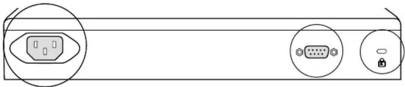
Back Panel
natural_image
Diagram of a computer interface panel showing ports and connectors (no text or symbols)AC Input Power
K-SlotMaintena
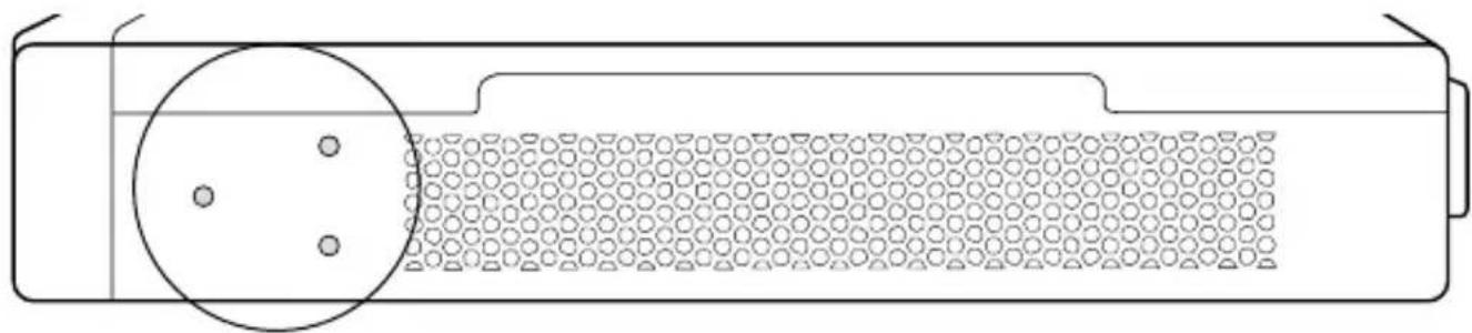
Side Panel
natural_image
Diagram of a battery cell with a circular component and hexagonal pattern inside (no text or symbols)Bolt Hole

natural_image
Diagram of a cylindrical device with two circular components and three dots, no text or symbols presentBolt HoleFan
Hardware Installation
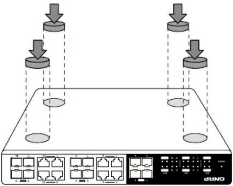
1 Horizontal Surface
Place four foot pads at the bottom of the QSwitch.
flowchart
graph TD
    A["Router 1"] -->|Data Flow Down| B["Switch"]
    C["Router 2"] -->|Data Flow Down| B
    D["Router 3"] -->|Data Flow Down| B
    E["Router 4"] -->|Data Flow Down| B
    F["Router 5"] -->|Data Flow Down| B
    G["Router 6"] -->|Data Flow Down| B
    H["Router 7"] -->|Data Flow Down| B
    I["Router 8"] -->|Data Flow Down| B
    J["Router 9"] -->|Data Flow Down| B
    K["Router 10"] -->|Data Flow Down| B
    L["Router 11"] -->|Data Flow Down| B
    M["Router 12"] -->|Data Flow Down| B
    N["Router 13"] -->|Data Flow Down| B
    O["Router 14"] -->|Data Flow Down| B
    P["Router 15"] -->|Data Flow Down| B
    Q["Router 16"] -->|Data Flow Down| B
    R["Router 17"] -->|Data Flow Down| B
    S["Router 18"] -->|Data Flow Down| B
    T["Router 19"] -->|Data Flow Down| B
    U["Router 20"] -->|Data Flow Down| B
2 Mounting in a Rack
Attach the rackmount brackets to the QSwitch using six bracket screws.
Attach the QSwitch to the rack using two mounting screws.

Connecting RJ45
5 Connect an Ethernet cable from your computer or host system to any RJ45 port of the QSwitch. Connect Ethernet cable from your device to other RJ45 ports of the QSwitch.

flowchart
graph TD
    A["ONAP"] -->|1| B["Server"]
    A -->|2| C["Data Port 1"]
    C --> D["Server"]
    D --> E["Computer"]
    style A fill:#f9f,stroke:#333
    style B fill:#ccf,stroke:#333
    style C fill:#cfc,stroke:#333
    style D fill:#fcc,stroke:#333
    style E fill:#cff,stroke:#333

Combo Port Instruction
You can only choose either SFP+ or RJ45 for connection. RJ45 will have higher priority if both connections are used.

Connecting Power
3 Connect the power cord to the power port of the QSwitch. Connect the other end of the power cord to a power outlet.

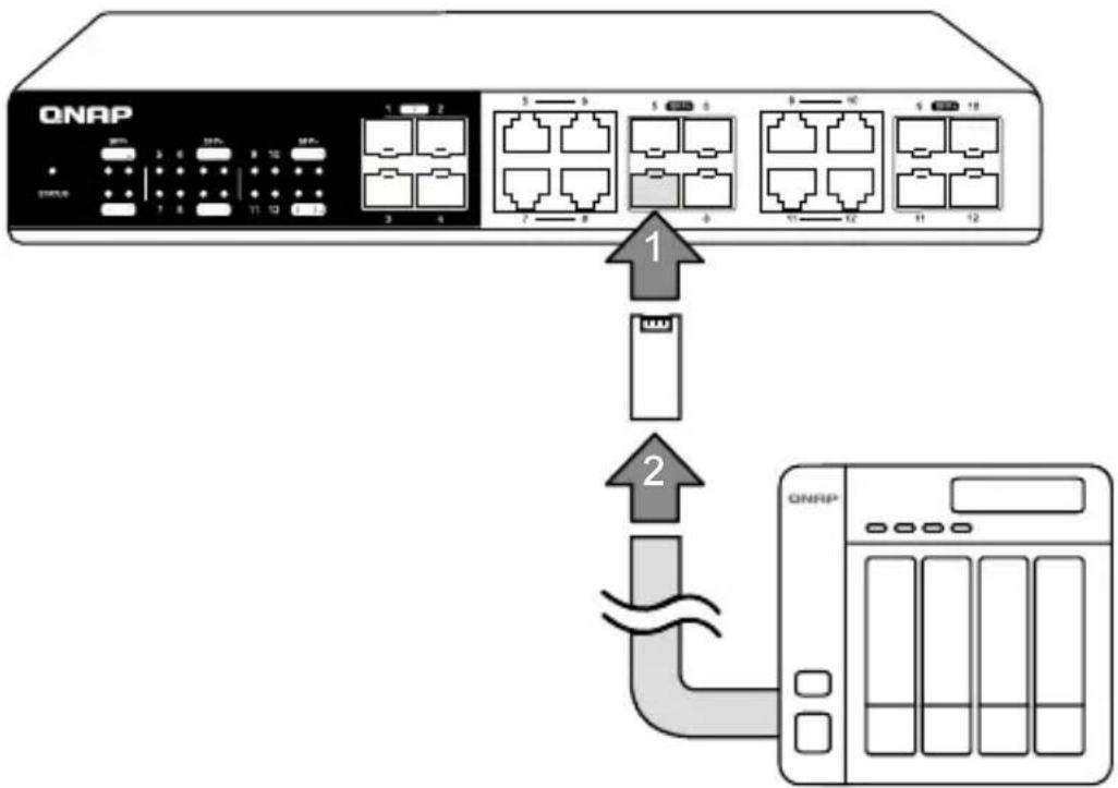
Connecting SFP+
4 Plug a compatible fiber module into any SFP+ port of the QSwitch. Connect an optical fiber cable to the fiber module. Then connect the other end of the cable to another fiber device.
flowchart
graph TD
    A["QNAP"] -->|1| B["USB Port"]
    A -->|2| C["USB Port"]
    B --> D["Switch 1"]
    C --> E["Switch 2"]
Specifications
| Model | |
| Dimensions (H x W x D) | |
| Net weight | |
| Supported voltage range | |
| Switching capacity | |
| SFP+ ports | |
| Combo ports (SFP+/RJ45) | |
| Operating temperature | |
| Relative humidity | wet bulb: 27°C |

natural_image
Line drawing of a network switch device (ONAP) with ports and indicator lights (no text or symbols on the device body)
This device complies with Part 15 of the FCC Rules. Operation is subject to the following two conditions:
- This device may not cause harmful interference.
- This device must accept any interference received, including interference that may cause undesired operation.
FCC Class A Notice:
This equipment has been tested and found to comply with the limits for a Class A digital device, pursuant to Part 15 of the FCC Rules. These limits are designed to provide reasonable protection against harmful interference when the equipment is operated in a commercial environment. This equipment generates, uses, and can radiate radio frequency energy, and if not installed and used in accordance with the instruction manual, may cause harmful interference to radio communications. Operation of this equipment in a residential area is likely to cause harmful interference, in which case the user will be required to correct the interference at his own expense.
Modifications: Any modifications made to this device that are not approved by QNAP Systems, Inc. may void the authority granted to the user by the FCC to operate this equipment.

This device complies with CE compliance Class A.

According to the requirement of the WEEE legislation the following user information is provided to customers for all branded QNAP Electronics products subject to the WEEE directive.
This symbol on the product or on its packaging indicates that this product must not be disposed of with your other household waste. Instead, it is your responsibility to dispose of your waste equipment by handing it over to a designated collection point for the recycling of waste electrical and electronic equipment. The separate collection and recycling of your waste equipment at the time of disposal will help to conserve natural resources and ensure that it is recycled in a manner that protects human health and the environment. For more information about where you can drop off your waste equipment for recycling, please contact your local city office, your household waste disposal service or the shop where you purchased the product.

D33B77 RoHS
Brand : QNAP
Model : QSW-1208-8C
Category : Network switch