1024BEVS-00A - Wine cellar U-Line - Free user manual and instructions
Find the device manual for free 1024BEVS-00A U-Line in PDF.


| Product Type | Built-In Wine Cellar |
| Brand | U-Line |
| Model | 1024BEVS-00A |
| Capacity | Approximately 24 bottles |
| Dimensions (W x H x D) | 23 7/8 x 34 1/2 x 23 7/8 inches |
| Weight | Approximately 120 lbs |
| Power Supply | 115 V / 60 Hz / 1.5 Amps |
| Temperature Range | 40°F to 65°F (4°C to 18°C) |
| Number of Zones | 1 Zone |
| Door Type | Full-Glass, Stainless Steel Frame |
| Installation | Undercounter or Built-In |
| Cooling System | Compressor with Vibration Dampening |
| Shelving | Stainless Steel or Wood Shelves |
| Interior Light | LED Lighting |
| Lock | Key Lock |
| Energy Consumption | Approximately 1.5 kWh per day |
| Compressor Warranty | 5 Years |
| Parts Warranty | 2 Years |
| Cleaning | Mild soap and water; avoid abrasive cleaners |
| Replacement Parts | Available through authorized U-Line distributors |
Frequently Asked Questions - 1024BEVS-00A U-Line
User questions about 1024BEVS-00A U-Line
0 question about this device. Answer the ones you know or ask your own.
Ask a new question about this device
Download the instructions for your Wine cellar in PDF format for free! Find your manual 1024BEVS-00A - U-Line and take your electronic device back in hand. On this page are published all the documents necessary for the use of your device. 1024BEVS-00A by U-Line.
USER MANUAL 1024BEVS-00A U-Line
natural_image
Modern white kitchen interior with stainless steel appliances, large windows, and open storage (no visible text or symbols)1000 Series • 1024BEV • 24" Beverage Center
SAFETY • INSTALLATION & INTEGRATION • OPERATING INSTRUCTIONS • MAINTENANCE • SERVICE
Tip: Click on any section below to jump directly there
Contents
Intro
Wine Rack Installation
Light Replacement
Safety
Safety and Warning
Extended Non-Use
Disposal
Service
Troubleshooting
Installation
Warranty
Environmental Requirements
Electrical
Cutout Dimensions
Product Dimensions
Side by Side Installation
Anti-Tip Bracket
General Installation
Grille / Plinth Installation
Door Swing
Door Stop
Door Adjust
Wood Trim Finishing
Free Standing Kit
Operating Instructions
First Use
Airflow and Product Loading
U-Line Wine Guide
Recommended Wine Storage
Interior Shelves
Maintenance
Cleaning
Cleaning Condenser
WELCOME TO U-LINE
Congratulations on your U-Line purchase. Your product comes from a company with over five decades and three generations of premium modular ice making, refrigeration, and wine preservation experience. U-Line continues to be the American leader, delivering versatility and flexibility for multiple applications including residential, light commercial, outdoor and marine use. U-Line's complete product collection includes modular Wine Captain® Models, Beverage Centers, Clear Ice Machines, Crescent Ice Makers, Glass & Solid Door Refrigerators, Drawer Models, Freezers, and Combo® Models.
U-Line has captivated those with an appreciation for the finer things with exceptional functionality, style, inspired innovations and attention to even the smallest details. We are known and respected for our unwavering dedication to product design, quality and selection. U-Line is headquartered in Milwaukee, Wisconsin with a west coast office located in Laguna Beach, California and European support in Dublin, Ireland. U-Line has shipped product to five continents for over two decades and is proud to have the opportunity to ship to you.
PRODUCT INFORMATION
Looking for additional information on your product? User Guides, Quick Reference Guides, CAD Drawings, Compliance Documentation, and Product Warranty information are all available for reference and download at u-line.com under Documentation.
PROPERTY DAMAGE / INJURY CONCERNS
In the unlikely event property damage or personal injury is suspected related to a U-Line product, please take the following steps:
- U-Line Customer Care must be contacted immediately at +1.800.779.2547.
- Service or repairs performed on the unit without prior written approval from U-Line is not permitted. If the unit has been altered or repaired in the field without prior written approval from U-Line, claims will not be eligible.
SERVICE INFORMATION
Answers to Customer Frequently Asked Questions are available at u-line.com under Customer Care or you may contact our Customer Care group directly, contact information below.
GENERAL INQUIRIES
U-Line Corporation
8900 N. 55th Street
Milwaukee, Wisconsin 53223 USA
Monday - Friday 8:00 am to 4:30 pm CST
T: +1.414.354.0300
F: +1.414.354.7905
Email: sales@u-line.com
u-line.com
SERVICE & PARTS ASSISTANCE
Monday - Friday 8:00 am to 5:30 pm CST
T: +1.800.779.2547
F: +1.414.354.5696
Service Email: onlineservice@u-line.com
Parts Email: onlineparts@u-line.com
CONNECT WITH US
f Twitter g+ YouTube in blog
Designed, engineered and assembled in WI, USA
SAFETY · INSTALLATION & INTEGRATION · OPERATING INSTRUCTIONS · MAINTENANCE · SERVICE
Safety and Warning
NOTICE
Please read all instructions before installing, operating, or servicing the appliance.
Use this appliance for its intended purpose only and follow these general precautions with those listed throughout this guide:
SAFETY ALERT DEFINITIONS
Throughout this guide are safety items labeled with a Danger, Warning or Caution based on the risk type:

DANGER
Danger means that failure to follow this safety statement will result in severe personal injury or death.

WARNING
Warning means that failure to follow this safety statement could result in serious personal injury or death.

CAUTION
Caution means that failure to follow this safety statement may result in minor or moderate personal injury, property or equipment damage.

DANGER
This unit contains R600a (Isobutane) which is a flammable hydrocarbon. It is safe for regular use. Do not use sharp objects to expedite defrosting. Do not service without consulting the "R600a specifications" section included in the User Guide. Do not damage the refrigerant circuit.

WARNING
Service must be done by factory authorized service personnel. Any parts shall be replaced with like components. Failure to comply could increase the risk of possible ignition due to incorrect parts or improper service.
SAFETY • INSTALLATION & INTEGRATION • OPERATING INSTRUCTIONS • MAINTENANCE • SERVICE
Disposal and Recycling

DANGER
RISK OF CHILD ENTRAPMENT. Before you throw away your old refrigerator or freezer, take off the doors and leave shelves in place so children may not easily climb inside.
If the unit is being removed from service for disposal, check and obey all federal, state and local regulations regarding the disposal and recycling of refrigeration appliances, and follow these steps completely:
- Remove all consumable contents from the unit.
- Unplug the electrical cord from its socket.
- Remove the door(s)/drawer(s).
SAFETY • INSTALLATION & INTEGRATION • OPERATING INSTRUCTIONS • MAINTENANCE • SERVICE
Environmental Requirements
This model is intended for indoor/interior applications only and is not to be used in installations that are open/exposed to natural elements.
This unit is designed to operate between 50°F (10°C) and 100°F (38°C). Higher ambient temperatures may reduce the unit's ability to reach low temperatures and/or reduce ice production on applicable models.
For best performance, keep the unit out of direct sunlight and away from heat generating equipment.
In climates where high humidity and dew points are present, condensation may appear on outside surfaces. This is considered normal. The condensation will evaporate when the humidity drops.
CAUTION
Damages caused by ambient temperatures of 40^ F ( 4^ C) or below are not covered by the warranty.
SAFETY • INSTALLATION & INTEGRATION • OPERATING INSTRUCTIONS • MAINTENANCE • SERVICE
Electrical
SHOCK HAZARD — Electrical Grounding
Required. Never attempt to repair or perform maintenance on the unit until the electricity has been disconnected.
Never remove the round grounding prong from the plug and never use a two-prong grounding adapter.
Altering, cutting or removing power cord, removing power plug, or direct wiring can cause serious injury, fire, loss of property and/or life, and will void the warranty.
Never use an extension cord to connect power to the unit.
Always keep your working area dry.
NOTICE
Electrical installation must observe all state and local codes. This unit requires connection to a grounded (three-prong), polarized receptacle that has been placed by a qualified electrician.
The unit requires a grounded and polarized 115 VAC, 60 Hz, 15A power supply (normal household current). An individual, properly grounded branch circuit or circuit breaker is recommended. A GFCI (ground fault circuit interrupter) is usually not required for fixed location appliances and is not recommended for your unit because it could be prone to nuisance tripping. However, be sure to consult your local codes.
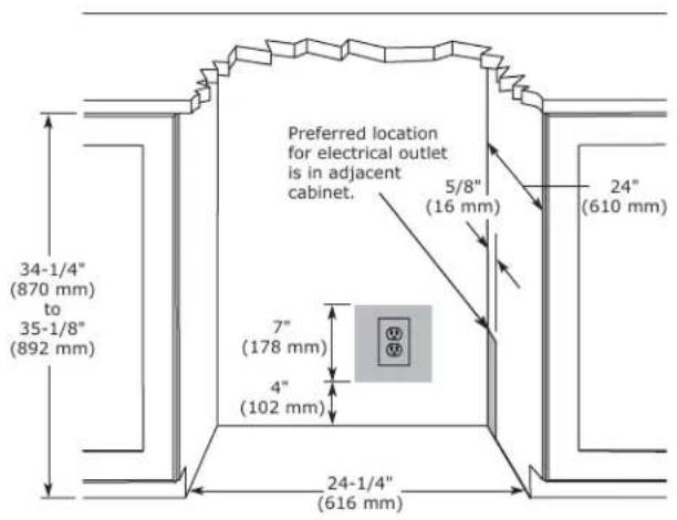
See CUTOUT DIMENSIONS for recommended receptacle location.
SAFETY • INSTALLATION & INTEGRATION • OPERATING INSTRUCTIONS • MAINTENANCE • SERVICE
Cutout Dimensions
PREPARE SITE
Your U-Line product has been designed for either freestanding or built-in installation. When built-in, your unit does not require additional air space for top, sides, or rear. However, the front grille must NOT be obstructed, and clearance is required for an electrical connection in the rear.
CAUTION
Unit can NOT be installed behind a closed cabinet door.
CUTOUT DIMENSIONS
SAFETY • INSTALLATION & INTEGRATION • OPERATING INSTRUCTIONS • MAINTENANCE • SERVICE
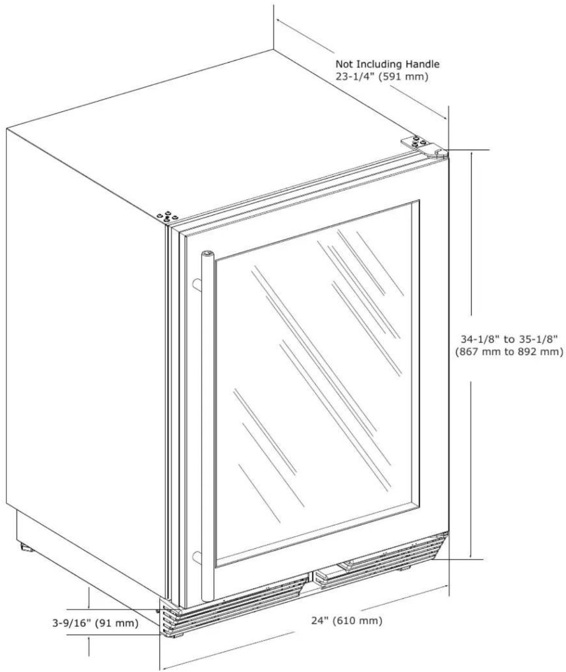
Product Dimensions
SAFETY • INSTALLATION & INTEGRATION • OPERATING INSTRUCTIONS • MAINTENANCE • SERVICE
Side-by-Side Installation
Two units may be installed side-by-side.
Cutout width for a side-by-side installation is the cutout dimension of a single unit times two.
No trim kit is required. However, 1/4" (6 mm) of space needs to be maintained between the units to ensure unobstructed door swing.
Units must operate from separate, properly grounded electrical receptacles placed according to each unit's electrical specifications requirements.
Side-by-Side Installation with Bracket
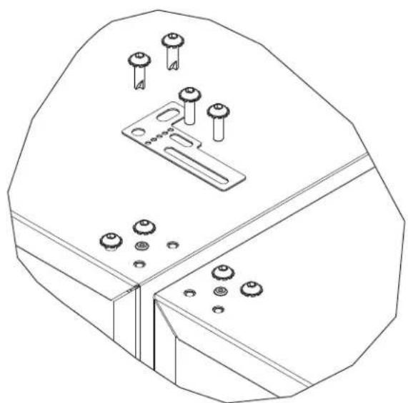
- Slide both units out so screws on top of units are easily accessible.
- Remove screws as shown below.
natural_image
Technical line drawing of a mechanical assembly with multiple bolt holes and a central component (no text or symbols)- Place bracket over holes and attach to unit with two screws removed in step 2 using a T-25 Torx driver. Tighten screws fully.
- Gently push units into position. Be careful not to entangle the electrical cord or water line, if applicable.
- Re-check the leveling, from front to back and side to side. Make any necessary adjustments. The unit's top surface should be approximately 1/8" (3 mm) below the countertop.
SAFETY • INSTALLATION & INTEGRATION • OPERATING INSTRUCTIONS • MAINTENANCE • SERVICE
Anti-Tip Bracket
-
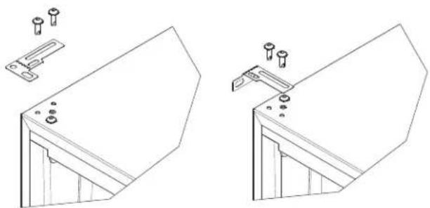
Slide unit out so screws on top of unit are easily accessible.
-
Remove the two screws from the opposite side of the hinge assembly using a T-25 Torx driver (see below).
NOTE: 1224 models shown with four screw. 1215 models only have three screws, but same screws are used in both applications.
natural_image
Technical line drawing of two mechanical bracket components with mounting holes and mounting screws (no text or symbols)-
Place bracket (part #14154) over holes and attach to unit with two screws removed in step 2 using a T-25 Torx driver. Tighten screws fully.
-
Gently push unit into position. Be careful not to entangle the electrical cord or water line, if applicable.
-
Check to be sure the unit is level from front to back and side to side. Make any necessary adjustments. The unit's top surface should be approximately 1/8" (3 mm) below the countertop.
-
Secure bracket into adjoining surface.
SAFETY • INSTALLATION & INTEGRATION • OPERATING INSTRUCTIONS • MAINTENANCE • SERVICE
General Installation
LEVELING INFORMATION
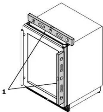
- Use a level to confirm the unit is level. Level should be placed along top edge and side edge as shown.
natural_image
Technical line drawing of a mechanical cabinet or enclosure with mounting brackets and a labeled component (no text or symbols present)- If the unit is not level, adjust the legs on the corners of the unit as necessary.
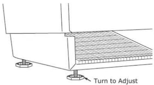
- Confirm the unit is level after each adjustment and repeat the previous steps until the unit is level.
INSTALLATION TIP
If the room floor is higher than the floor in the cutout opening, adjust the rear legs to achieve a total unit rear height of 1/8" (3 mm) less than the opening's rear height. Shorten the unit height in the front by adjusting the front legs. This allows the unit to be gently tipped into the opening. Readjust the front legs to level the unit after it is correctly positioned in the opening.
INSTALLATION
-
Plug in the power/electrical cord.
-
Gently push the unit into position. Be careful not to entangle the cord.
-
Re-check the leveling, from front to back and side to side. Make any necessary adjustments. The unit's top surface should be approximately 1/8" (3 mm) below the countertop.
-
Remove the interior packing material and wipe out the inside of the unit with a clean, water-dampened cloth.
SAFETY • INSTALLATION & INTEGRATION • OPERATING INSTRUCTIONS • MAINTENANCE • SERVICE
Grille - Plinth Installation
REMOVING AND INSTALLING GRILLE

WARNING
Disconnect electric power to the unit before removing the grille.
When using the unit, the grille (plinth strip/base fascia) must be installed.

WARNING
DO NOT touch the condenser fins. The condenser fins are SHARP and can be easily damaged.
Removing the grille
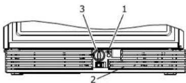
- Disconnect power to the unit.
- Remove control knob (3).
- Loosen the screw (1) in the center.
- Remove grille (2) from unit.
Installing the grille
- Place the hook-hinge located on the rear bottom side of the grille (2) onto the front lip of the unit base. Swing the grille up into position.
- Align cabinet and grille hole and secure, but do not over tighten grille screw (1).
- Install control knob (3).
- Reconnect power to the unit.
SAFETY • INSTALLATION & INTEGRATION • OPERATING INSTRUCTIONS • MAINTENANCE • SERVICE
Door Swing
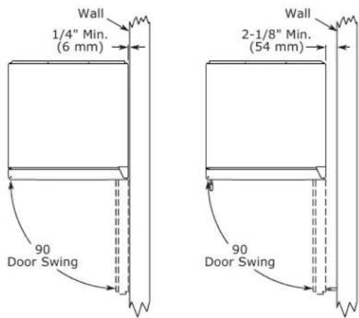
Units have a zero clearance for the door to open 90°, when installed adjacent to cabinets.
Stainless Steel and black and white models require 2-1/8" (54 mm) door clearance to accommodate the handle if installed next to a wall.
Integrated models require 1/4" (6 mm) clearance if installed next to a wall. Allow for additional space for any knobs or pulls installed on the integrated panel/frame.
SAFETY • INSTALLATION & INTEGRATION • OPERATING INSTRUCTIONS • MAINTENANCE • SERVICE
Door Stop
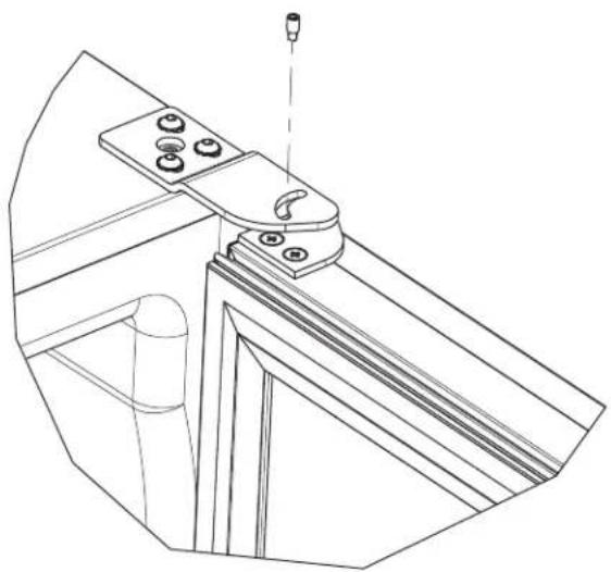
Your U-Line unit was shipped to you with the optional 90° pin(s). (Models that are 15" wide include 1 pin. Models that are 24" wide include 2 pins.) The unit's door will open freely without a fixed opening angle limitation. If you would like the door stop at 90° follow these instructions.
NOTICE
The pin is designed to stop the door at 90^ under normal operating conditions. It is not designed for excessive force. Do not use the door to move the unit in/out of the cutout during installation.
If your unit is already undercounter, it might need to be moved out/forward to access the hinge.
- Locate the threaded pin.
- With the door between 0° (closed) and 90° and using a 3/32" hex driver, install the threaded pin through the hinge.
natural_image
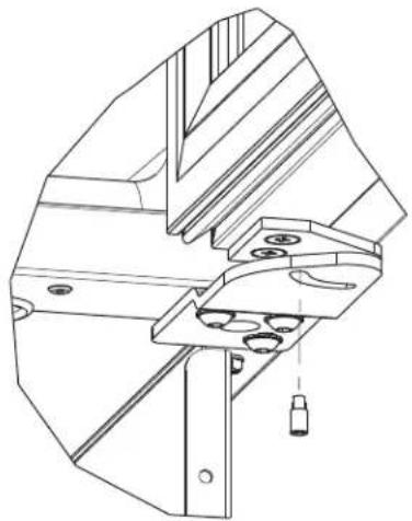
Technical line drawing of a mechanical bracket assembly (no text or symbols)- On 24" models, a second pin is included for the bottom hinge. Repeat steps above for second hinge.
NOTE: Threaded pin will be inserted from the bottom.
natural_image
Technical line drawing of a mechanical assembly with no visible text or symbols- Carefully slide your unit back in place.
NOTICE
The pin can be removed to return the door swing back to its original state by unscrewing the threaded pin.
SAFETY • INSTALLATION & INTEGRATION • OPERATING INSTRUCTIONS • MAINTENANCE • SERVICE
Door Adjustments
DOOR ALIGNMENT AND ADJUSTMENT
Align and adjust the door if it is not level or is not sealing properly. If the door is not sealed, the unit may not cool properly, or excessive frost may form in the interior.
NOTICE
Properly aligned, the door's gasket should be firmly in contact with the cabinet all the way around the door (no gaps). Carefully examine the door's gasket to ensure that it is firmly in contact with the cabinet. Also make sure the door gasket is not pinched on the hinge side of the door.
To align and adjust the door:
- Remove grille (see GRILLE-PLINTH INSTALLATION).
- Loosen (do not remove) top and bottom hinge screws.
- Align door squarely with cabinet.
- Make sure gasket is firmly in contact with cabinet all the way around the door (no gaps).
- Tighten bottom hinge screws.
- Tighten top hinge screws.
REVERSING THE DOOR
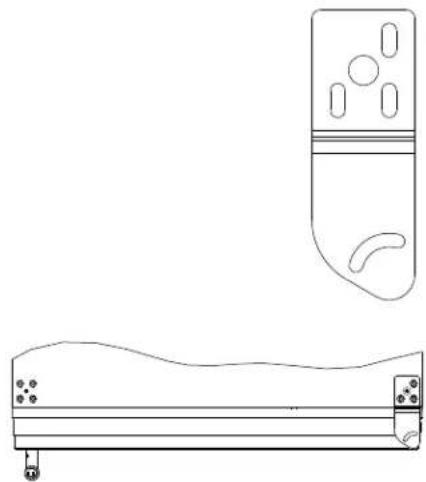
Location of the unit may make it desirable to mount the door on the opposite side of the cabinet.
The hinge hardware will be removed and installed on the opposite side of the cabinet.
natural_image
Line drawing of a medical device with a separate view showing internal components (no text or symbols)TO REVERSE THE DOOR
Remove grille:
Remove the grille (see GRILLE-PLINTH INSTALLATION section of this guide).
Remove door:
- Hold door to keep it from falling.
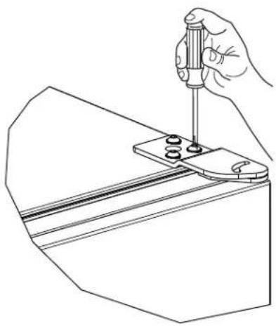
- Remove top hinge from cabinet by removing three screws.
natural_image
Line drawing of a hand using a screwdriver to adjust or install a component on a flat surface (no text or symbols)SAFETY • INSTALLATION & INTEGRATION • OPERATING INSTRUCTIONS • MAINTENANCE • SERVICE
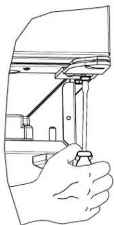
- Remove bottom hinge from cabinet by removing three screws. Support the door and hinge assembly and remove it from the cabinet.
natural_image
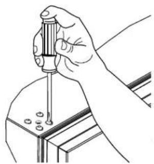
Line drawing of a hand operating a mechanical device with a handle (no text or symbols)- Remove four screws from hinge holes on the opposite side. Reinstall into holes where the hinge was removed. Take care not to scratch cabinet.
natural_image
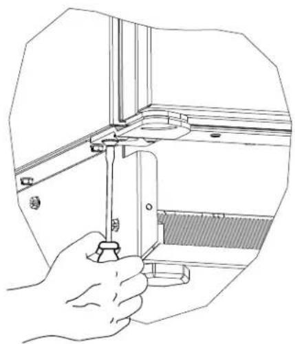
Line drawing of a hand using a pipette to measure a component (no text or symbols present)- Repeat for cabinet base.
Prepare door for reinstallation:
- Rotate door 180^ to reverse.
- Remove gasket. This will reveal mounting holes for the door light activation bracket.
- Remove door light activation bracket from door. Be sure to only remove the two screws holding the bracket to the door. Reinstall the bracket on the opposite end of the door.
- Install gasket, aligning notch with bracket and pressing firmly into the gasket channel.
- Align the flat edge of the hinge with the outer edge of the cabinet.
- Hold door to keep from falling.
- Tighten three screws.
natural_image
Line drawing of a hand using a tool to adjust or install a mechanical component (no text or symbols present)SAFETY • INSTALLATION & INTEGRATION • OPERATING INSTRUCTIONS • MAINTENANCE • SERVICE
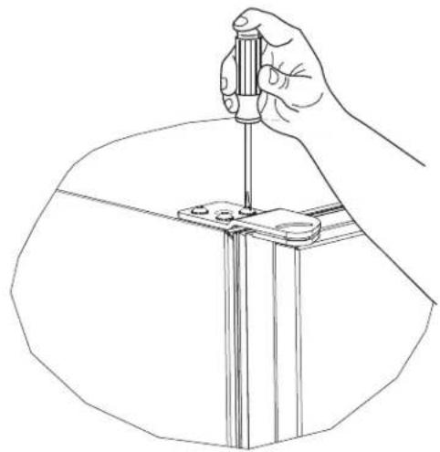
- Align flat edge of the hinge with the outer edge of the unit.
- Tighten three screws.
natural_image
Line drawing of a hand using a tool to adjust or install a mechanical component (no text or symbols present)SHIFTING WINE RACK SPACERS (OPTIONAL)
NOTICE
Only perform these steps if you require wine rack clearance with a 90° door opening. Doors which are allowed to open past 90° do not require this step.
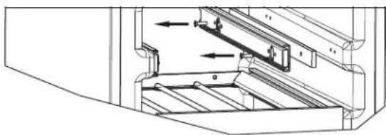
- Remove wine rack (see WINE RACK INSTALLATION in Maintenance).
- Starting from the side that has the spacers (previously unaltered units will be on the right hand side from the factory), remove 2 screws, slide and spacer.
natural_image
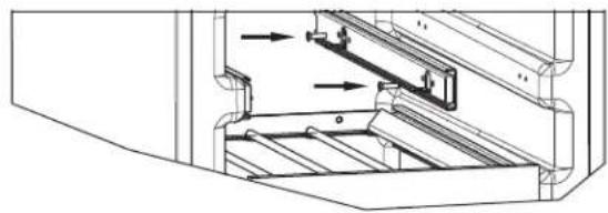
Technical line drawing of a mechanical assembly with internal components and directional arrows (no text or symbols)- Reinstall the slide with the original 2 screws.
natural_image
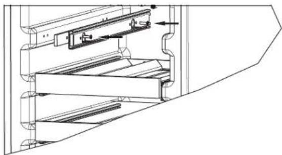
Technical line drawing of a mechanical assembly with internal components and directional arrows (no text or symbols)- Remove 2 screws from the other side.

natural_image
Technical line drawing of a mechanical assembly with layered components and mounting brackets (no text or symbols)- Place the spacer in between the liner and slide.
natural_image
Technical line drawing of a mechanical assembly with no visible text or symbols- Install original hardware.
- Slide wine rack back into position.
Align and adjust the door:
Align and adjust the door (see DOOR ALIGNMENT AND ADJUSTMENT).
Install grille:
Install the grille.
SAFETY • INSTALLATION & INTEGRATION • OPERATING INSTRUCTIONS • MAINTENANCE • SERVICE
Wood Trim Finishing
The wine rack fronts are solid natural beech wood. They are factory coated with a clear vinyl sealer, which will sufficiently protect the wood in normal use.
You may coat the trim with stain and/or a final finish to match surrounding cabinetry.

CAUTION
You MUST remove the wood trim from the unit for staining or finishing to prevent permanent damage to the inner liner of the unit. Allow stain or finish to dry thoroughly (at least 24 hours for each coat) following the product manufacturer's instructions before reinstallation. Not following this warning may cause the inner liner of the unit to have a permanent odor, which the warranty will not cover.
U-Line recommends Minwax ^® Brand Water Based Stains and Minwax Polycrylic ^® Protective Finish.
NOTICE
Never use oil based stains or finishes.
On glass door models, the stain may appear darker when viewed through the glass.
Follow the manufacturers instructions for the stain and/or finish you select.
SAFETY • INSTALLATION & INTEGRATION • OPERATING INSTRUCTIONS • MAINTENANCE • SERVICE
Free Standing Kit
The free standing kit is an optional accessory. It is only used when unit is not installed in surrounding cabinetry.
To install the kit:
- Remove grille (see GRILLE-PLINTH INSTALLATION section).
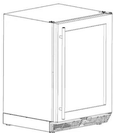
natural_image
Line drawing of a refrigerator with lid and side panel (no text or symbols)- Place shell accessory over front and back of cabinet base, aligning holes of shell accessory with the holes on the base. Insert sheet metal screw in back of base.
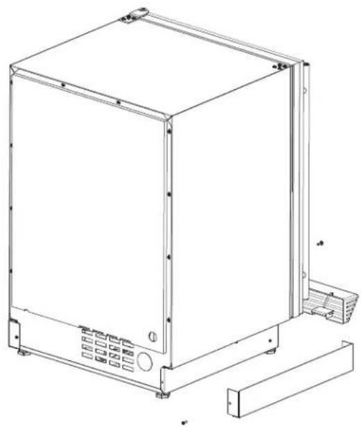
natural_image
Technical line drawing of a rectangular industrial machine or enclosure with mounting brackets and control panel (no text or symbols)- Align front hole with hole in shell accessory, hole in base, and hole in grille. Tighten screw.
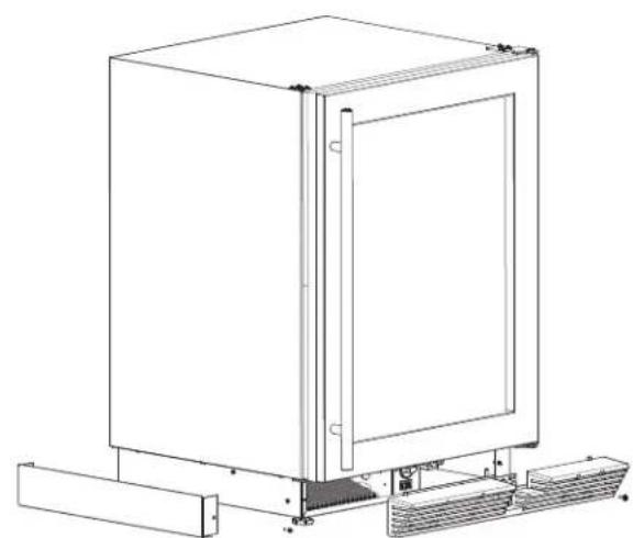
natural_image
Line drawing of a refrigerator with front panel and side-mounted base (no text or symbols)SAFETY • INSTALLATION & INTEGRATION • OPERATING INSTRUCTIONS • MAINTENANCE • SERVICE
First Use
All U-Line controls are preset at the factory. Initial startup requires no adjustments.
NOTICE
U-Line recommends allowing the unit to run overnight before loading with product.
MECHANICAL DIAL CONTROL
The control dial turns unit ON/OFF and sets temperature. This set point temperature is a base setting used by the controller to maintain the temperature zone in the unit. The factory default MID setting, number 4 set point, is approximately 38°F (3°C). The set point temperature is a gauge for further temperature adjustments.
SAFETY • INSTALLATION & INTEGRATION • OPERATING INSTRUCTIONS • MAINTENANCE • SERVICE
Airflow and Product Loading
NOTICE
The unit requires proper airflow to perform at its highest efficiency. Do not block the front grille, or the unit will not perform as expected. Do not install the unit behind a door. When loading your unit, leave space between the evaporator and product loaded. Anything in direct contact with the evaporator is subject to freezing.
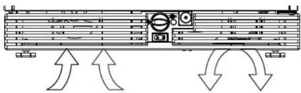
natural_image
Diagram of a computer monitor with ventilation system and directional arrows indicating airflow or movement (no text or symbols)When properly loaded, your U-Line unit will store up to 105 (12 oz. [330 ml]) cans or 85 (12 oz. [330 ml]) bottles and 16 (750 ml) bottles of wine.
SAFETY • INSTALLATION & INTEGRATION • OPERATING INSTRUCTIONS • MAINTENANCE • SERVICE
U-Line Wine Guide
To most, wine is a delicious mystery. We purchase it, uncork it, and savor its taste and beauty. But there is so much more to true wine appreciation. Many secrets are simply too good to keep bottled up.
WINE SELECTIONS SUGGESTIONS
Selecting the right wine for the right occasion can sometimes be a seemingly awkward or difficult task for the beginning wine enthusiast. We would therefore like to present you with a few suggestions which may provide a little more confidence and enjoyment when choosing and serving your wines.
When selecting wines, keep an open mind and do not be afraid to be adventurous. Do not view the subject of wine so seriously it discourages you from learning and discovering for fear of embarrassment if something is incorrect. Wine is best viewed as a hobby and enjoyed.
When assembling your collection, try not to become obsessed with "Vintages." Although a chart can be a useful tool, generalizations about a specific year have led more than one collector to disappointment. Often an "Off Year" will provide a better value and more drinking enjoyment.
The primary guideline to the subject of wine is your own palate. Do not be afraid to make mistakes. Experiment, discover, but most of all, enjoy yourself and your new U-Line product.
Guide To Common Styles Of Wine
| Red Wines | ||
| Full-Bodied Dry | California French Italian | Zinfandel, Cabernet Rhone, Chateauneuf-du-Pape Barbaresco, Barolo |
| Medium-Bodied Dry | California French | Pinot Noir Bordeaux, Burgundy |
| Light-Bodied Dry | French Italian | Beaujolais Chianti, Bardolino |
| White Wines | ||
| Full-Bodied Dry | California French | Chardonnay Montrachet, Meursault Puligny-Montrachet |
| Medium-Bodied Dry | California French | Sauvignon-Blanc Pouilly-Fuisse, Sancerre, Vouvray, Graves |
| Light-Bodied Dry | French | Chablis, Muscadet, Pouilly-Fume |
| Full-Bodied, Very Sweet | Germany French Hungary | Beerenauslese Sauternes Tokay |
| Medium-Bodied, Semi-Sweet | California Germany | Gewurtztraminer Liebfraumilch |
| Light-Bodied Off Dry | Germany | Rhine, Mosel, Riesling |
Matching Food and Wine
Although there are no hard fast rules for matching wine to food, observe some guidelines. Delicate dishes should be accompanied by lighter more delicate wines. Full-flavored foods should be matched with fuller-bodied wines.
As a general rule, one should aim to ascend in flavor and quality of wines served.
| Serve a: | Before a: |
| DRY wine | SWEET wine |
| WHITE wine | RED wine |
| YOUNG wine | OLD wine |
| LIGHT-BODIED wine | FULL-BODIED wine |
Any step back in quality will be noticed. If a fine wine is tasted prior to a lesser wine, many of the fine wine's subtle qualities may be missed.
SAFETY • INSTALLATION & INTEGRATION • OPERATING INSTRUCTIONS • MAINTENANCE • SERVICE
Common Food and Wine Matches
| Foods | Wines |
| Fish, Shell Fish, Crab, Oysters | Dry White Wines, Light Sparkling or Extra Dry Champagne |
| Beef, Venison | Full-Bodied Red Wines |
| Pork, Veal, Lamb and Poultry | Light-Bodied Red Wines |
| Fruit | Sweet White and Sparkling Wines |
A Toast to Wine Truths
Like the grapes themselves, many wine myths have been cultivated over the centuries.
Myth 1: Most wines taste better when aged.
Truth: In fact, less than 5% of wines produced today are meant to be aged. Most wines are crafted to be consumed within the first one to two years.
Myth 2: Wines should be uncorked and decanted allowing them to "breathe."
Truth: To breathe or not breathe? While it is better to allow a young tannic Red to breathe in a glass or decanter to soften the tannins, an old Red reaches a stage in its life where it should be enjoyed soon after opening. Allow an old Red to breathe for a short time to dissipate any off odors. Most white wines can be served, ideally, 10-15 minutes after opening.
Myth 3: When age worthy wines peak, they must be consumed almost immediately.
Truth: Most great wines reach a plateau period rather than a peak. Great Bordeaux's may have as much as a 10-year plateau before fading.
Myth 4: Wine color does not change with aging.
Truth: As red wines age they get lighter in color while whites get darker.
The Cork: A Mystery on Its Own
Cork Presentation. The ritual of the presentation of the cork has a rich and fascinating history dating back to the late 1800's. A phylloxera (root louse) devastation to the vineyards severely limited the supply of great wines.
Restaurateurs would remove labels on inferior wines and replace them with labels from superior wines. This made it necessary for patrons to protect themselves by checking the branding on the cork to ensure that what they ordered was, in fact, what they were served.
When presented with a cork today, feel it to check for its integrity, read and match the branding on the cork to the bottle and set it aside. There is little to be learned from the cork. The proof is in the wine.
"Corked" wines. If you've ever had a wine that smelled or tasted of mold, you've experienced a wine that may have been "corked." Today, between five and eight percent of wines are tainted with Trichloroanisole (TCA). This substance, found naturally in plants and trees, is imparted to the wine through the cork. Corked wines are a major concern for winemakers as it destroys millions of cases per year and puts reputations at stake. Amazing as it may seem twist-off caps may offer a better alternative and many great wineries in California, Australia and New Zealand are pioneering the trend.
SAFETY • INSTALLATION & INTEGRATION • OPERATING INSTRUCTIONS • MAINTENANCE • SERVICE
Common Tasting Terms
| Terminology | Description |
| Acidity | A critical element of wine that is responsible for preserving the wines freshness. Excess acidity results in an overly tart and sour wine. |
| Balance | A desired trait where tannin, fruit and acidity are in total harmony. Wines with good balance tend to age gracefully. |
| Body | The weight and presence of wine in the mouth provided by the alcohol and tannin level. Full-bodied wines tend to have this strong concentration. |
| Bouquet | The blending of a wine's aroma within the bottle over a period of time, caused by volatile acidity. |
| Complex | A subjective term often used in tasting. A wine is said to be complex if it offers a variety of flavors and scents that continue to evolve as it develops. |
| Flabby | A wine that lacks structure, or is heavy to the taste, lacks acidity. |
| Full-Bodied | Wine high in alcohol and extract, generally speaking, fills the mouth, powerful. |
| Lean | Generally describes wines that are slim, lacking of generosity or thin. |
| Oaky | A desirable flavor imparted to wine if done in moderation. Most wines are aged in oak barrels one to three years, thereby receiving this toasty oak characteristic. However, if a weak wine is left in contact too long with an oak barrel it will tend to be overpowered with an oaky taste. |
| Tannin | Tannins are extracted from the grape skins and stems and are necessary for a well-balanced red wine. Tannins are easily identified in wine tasting as the drying sensation over the gums. Tannins generally fade as a wine ages. |
IDEAL WINE STORAGE CONSIDERATIONS
Temperature: The most important element about storage temperature is stability. If wine is kept in a stable environment between 40°F (7°C) and 65°F (21°C), it will remain sound. A small 1-2 degree temperature fluctuation within a stable environment is acceptable. Larger temperature fluctuations can affect the corks ability to seal, allowing the wine to "leak" from the bottle.
Humidity: The traditional view on humidity maintains that wines should be stored on their sides in 50% - 80% relative humidity to ensure cork moisture and proper fit in the bottle. Contemporary wisdom suggests that the cork surface is too small to be impacted by humidity. Further the cork is sealed with a metal or wax capsule making humidity penetration impossible. The concept of a humid storage environment was derived from the necessity of wineries to maintain moisture in their cellars to keep wooden barrel staves swollen, preventing wine evaporation and product loss. In fact, vineyards estimate as much as a 10% product loss per year due to evaporation while wine is aging in the wooden barrels. Humidity, however, was not intended for the modern home cellar where wine is stored in glass bottles with sealed corks.
Light: UV rays are not only harmful to people, they are damaging to wines - especially those in clear bottles. Since oxygen molecules in wine absorb UV rays, wine should never be stored in direct light for long periods of time.
Vibration: Provided that sediment is left undistributed and particles are not suspended, vibration in a storage environment is not an issue. Wines can become flat or tired when voids and vacuums are created inside the wine bottle. In order to create voids and vacuums within a liquid, aggressive motion or shaking of the wine bottle would have to occur.
SAFETY • INSTALLATION & INTEGRATION • OPERATING INSTRUCTIONS • MAINTENANCE • SERVICE
The Right Temperature for Wine
| Temperature | Wines |
| Approximately 60°F (15°C) | Red |
| 50°F - 55°F (10°C -12°C) | White |
| Approximately 45°F (7°C) | Sparkling |
Wine Captain ^® Models - A Touch of Elegance
In 1985 U-Line was the first North American appliance manufacturer to develop a residential wine storage unit, the Wine Captain ^® . Each U-Line Wine Captain ^® model is designed to impress and inspire anyone with an interest in wine by providing cellar conditions in stylish, undercounter units. U-Line Wine Captain ^® models offer stable storage temperatures, a 50% internal relative humidity and protection from UV light rays. U-Line has the largest product offering available, making storing, presenting, and sharing your wine effortless and elegant.
SAFETY • INSTALLATION & INTEGRATION • OPERATING INSTRUCTIONS • MAINTENANCE • SERVICE
Recommended Wine Storage
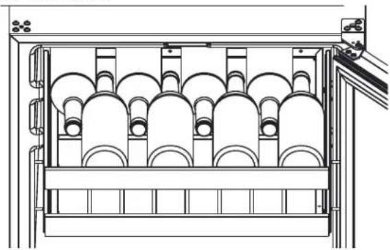
Specially designed horizontal wine racks properly position the bottles so the wine remains in contact with the cork, which ensures the cork does not become dry.
U-Line recommends arranging wine bottles as shown in the illustrations below.
Racks 1 and 2:
natural_image
Technical line drawing of a multi-tiered storage or processing unit with cylindrical tanks and piping (no text or symbols)NOTE: After stocking, allow unit to stabilize product temperatures for 24 hours.
SAFETY • INSTALLATION & INTEGRATION • OPERATING INSTRUCTIONS • MAINTENANCE • SERVICE
Interior Shelves
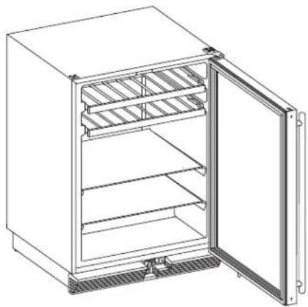
REMOVING AND INSTALLING INTERIOR SHELVES
natural_image
Line drawing of a refrigerator with open door and side shelves (no text or symbols)For models equipped with glass shelves having shelf supports, remove the shelves as follows:
- Open door completely.
- Grasp the shelf edge in the center and slide the shelf from the unit.
Insert the shelves as follows:
- With the door still fully opened, reposition the shelf as required, ensure the raised white edge strip is toward the rear of the unit and slide the shelf back into position.
NOTICE
Make sure the shelves are inserted fully into the unit.
The edge strip toward the rear prevents cans and bottles from freezing against the cold evaporator.
SAFETY • INSTALLATION & INTEGRATION • OPERATING INSTRUCTIONS • MAINTENANCE • SERVICE
Cleaning
EXTERIOR CLEANING
Vinyl Clad (Black or White)
Clean surfaces with a mild detergent and warm water solution. Do not use solvent-based or abrasive cleaners. Use a soft sponge and rinse with clean water. Wipe with a soft, clean towel to prevent water spotting.
Clean any glass surfaces with a non-chlorine glass cleaner.
Stainless Models
Stainless door panels, handles and frames can discolor when exposed to chlorine gas, pool chemicals, saltwater or cleaners with bleach.
Keep your stainless unit looking new by cleaning with a good quality all-in-one stainless steel cleaner and polish monthly. For best results use Claire® Stainless Steel Polish and Cleaner, which can be purchased from U-Line Corporation (Part Number 173348). Comparable products are acceptable. Frequent cleaning will remove surface contamination that could lead to rust. Some installations may require cleaning weekly.
Do not clean with steel wool pads.
Do not use stainless steel cleaners polishes on any glass surfaces.
Clean any glass surfaces with a non-chlorine glass cleaner.
Do not use cleaners not specifically intended for stainless steel on stainless surfaces (this includes glass, tile and counter cleaners).
If any surface discoloring or rusting appears, clean it quickly with Bon-Ami® or Barkeepers Friend Cleanser® and a nonabrasive cloth. Always clean with the grain. Always finish with Claire® Stainless Steel Polish and Cleaner or comparable product to prevent further problems.
Using abrasive pads such as Scotchbrite™ will cause the graining in the stainless steel to become blurred.
Rust not cleaned up promptly can penetrate the surface of the stainless steel and complete removal of the rust may not be possible.
Integrated Models
To clean integrated panels, use household cleaner per the cabinet manufacturer's recommendation.
INTERIOR CLEANING
Disconnect power to the unit.
Clean the interior and all removed components using a mild nonabrasive detergent and warm water solution applied with a soft sponge or non-abrasive cloth.
Rinse the interior using a soft sponge and clean water.
Do not use any solvent-based or abrasive cleaners. These types of cleaners may transfer taste to the interior products and damage or discolor the interior.
DEFROSTING
Under normal conditions this unit does not require manual defrosting. Minor frost on the rear wall or visible through the evaporator plate vents is normal and will melt during each off cycle.
If there is excessive build-up of 1/4" (6 mm) or more, manually defrost the unit.
Ensure the door is closing and sealing properly.
SAFETY • INSTALLATION & INTEGRATION • OPERATING INSTRUCTIONS • MAINTENANCE • SERVICE
High ambient temperature and excessive humidity can also produce frost.

CAUTION
DO NOT use an ice pick or other sharp instrument to help speed up defrosting. These instruments can puncture the inner lining or damage the cooling unit. DO NOT use any type of heater to defrost. Using a heater to speed up defrosting can cause personal injury and damage to the inner lining.
NOTICE
The drain pan was not designed to capture the water created when manually defrosting. To prevent water from overflowing the drain pan, place towels or other absorbent materials over the interior drain trough (under the evaporator) before defrosting.
To defrost:
- Disconnect power to the unit.
- Remove all products from the interior.
- Prop the door in an open position (2 in. [50 mm] minimum).
- Allow the frost to melt naturally.
- After the frost melts completely clean the interior and all removed components. (See INTERIOR CLEANING).
- When the interior is dry, reconnect power and turn unit on.
SAFETY • INSTALLATION & INTEGRATION • OPERATING INSTRUCTIONS • MAINTENANCE • SERVICE
Cleaning Condenser
INTERVAL - EVERY SIX MONTHS
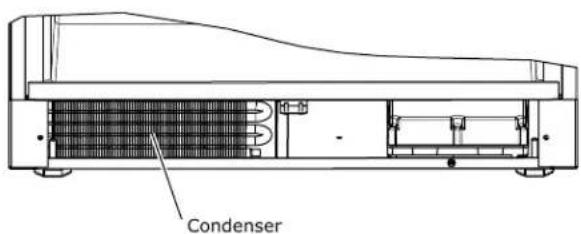
To maintain operational efficiency, keep the front grille free of dust and lint, and clean the condenser when necessary. Depending on environmental conditions, more or less frequent cleaning may be necessary.

WARNING
Disconnect electric power to the unit before cleaning the condenser.

WARNING
DO NOT touch the condenser fins. The condenser fins are SHARP and can be easily damaged.
NOTICE
DO NOT use any type of cleaner on the condenser unit.
- Remove the grille.
- Clean the condenser coil using a using a soft brush with a "combing" action or vacuum cleaner.
- Install the grille.
SAFETY • INSTALLATION & INTEGRATION • OPERATING INSTRUCTIONS • MAINTENANCE • SERVICE
Wine Rack Installation
To remove rack from the cabinet:
-
Remove any bottles stored on the rack.
-
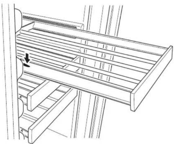
Grasp the end of the rack and gently slide it out until it stops.
natural_image
Technical line drawing of a mechanical assembly with no visible text or symbols- Press the left rack release lever down. At the same time, lift the matching right rack release lever up. Pull the rack out until it is free of the tracks and the cabinet.
NOTICE
Do not remove the track rails from the cabinet.
To insert rack in the cabinet:
-
Align the left and right rack channels with the tracks in the cabinet. Ensure an even track engagement on both sides by gently pushing the rack into the cabinet until it stops.
-
Before reloading the rack, ensure proper movement of the travel stops in the left and right track rails by pulling the rack out gently until it stops.
SAFETY • INSTALLATION & INTEGRATION • OPERATING INSTRUCTIONS • MAINTENANCE • SERVICE
Light Replacement
To replace the light bulb in your U-Line unit:
NOTICE
ALWAYS use a genuine U-Line replacement 120V 10 watt bulb (Part Number 31317) in the light housing. Use of any other bulb within the housing will produce excessive heat, causing damage to the light housing and cabinet interior, and will compromise the precise temperature control of the unit.
-
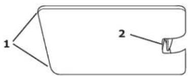
Find the light located at the top of the unit. Grasp the edges of the light housing lens (1) opposite the exposed tab and gently push the lens toward the tab (2).
-
Pull the edge of the lens down (1) and swing it out of the light housing.
natural_image
Simple line drawing of a mechanical component with two labeled parts (1 and 2), no text or symbols present.-
Remove old light bulb and install new light bulb into receptacle.
-
Replace the lens by first inserting the tab side back into the housing at a slight angle.
-
While gently pushing the lens towards the tab end, push the free end into the housing, and release when you hear a snap.
SAFETY • INSTALLATION & INTEGRATION • OPERATING INSTRUCTIONS • MAINTENANCE • SERVICE
Extended Non-Use
VACATION/HOLIDAY, PROLONGED SHUTDOWN
The following steps are recommended for periods of extended non-use:
- Remove all consumable content from the unit.
- Disconnect the power cord from its outlet/socket and leave it disconnected until the unit is returned to service.
- If ice is on the evaporator, allow ice to thaw naturally.
- Clean and dry the interior of the unit. Ensure all water has been removed from the unit.
- The door must remain open to prevent formation of mold and mildew. Open door a minimum of 2" (50 mm) to provide the necessary ventilation.
WINTERIZATION
If the unit will be exposed to temperatures of 40^ F ( 5^ C) or less, the steps above must be followed.
For questions regarding winterization, please call U-Line at +1.800.779.2547.

CAUTION
Damage caused by freezing temperatures is not covered by the warranty.
SAFETY • INSTALLATION & INTEGRATION • OPERATING INSTRUCTIONS • MAINTENANCE • SERVICE
Troubleshooting
BEFORE CALLING FOR SERVICE
If you think your U-Line product is malfunctioning, read the CONTROL OPERATION section to clearly understand the function of the control.
If the problem persists, read the NORMAL OPERATING SOUNDS and TROUBLESHOOTING GUIDE sections below to help you quickly identify common problems and possible causes and remedies. Most often, this will resolve the problem without the need to call for service.
IF SERVICE IS REQUIRED
If you do not understand a troubleshooting remedy, or your product needs service, contact U-Line Corporation directly at +1.800.779.2547.
When you call, you will need your product Model and Serial Numbers. This information appears on the Model and Serial number plate located on the upper right or rear wall of the interior of your product.
All models incorporate rigid foam insulated cabinets to provide high thermal efficiency and maximum sound reduction for its internal working components. Despite this technology, your model may make sounds that are unfamiliar.
Normal operating sounds may be more noticeable because of the unit's environment. Hard surfaces such as cabinets, wood, vinyl or tiled floors and paneled walls have a tendency to reflect normal appliance operating noises.
Listed below are common refrigeration components with a brief description of the normal operating sounds they make. NOTE: Your product may not contain all the components listed.
- Compressor: The compressor makes a hum or pulsing sound that may be heard when it operates.
- Evaporator: Refrigerant flowing through an evaporator may sound like boiling liquid.
- Condenser Fan: Air moving through a condenser may be heard.
- Automatic Defrost Drain Pan: Water may be heard dripping or running into the drain pan when the unit is in the defrost cycle.
TROUBLESHOOTING GUIDE

DANGER
ELECTROCUTION HAZARD. Never attempt to repair or perform maintenance on the unit before disconnecting the main electrical power.
Troubleshooting - What to check when problems occur:
| Problem | Possible Cause and Remedy |
| Interior Light Does Not Illuminate. | The light bulb may be defective.If the unit is cooling, it may be in Sabbath mode. |
| Light Remains on When Door Is Closed. | For glass door models, press the light icon and close the door.Check light actuator under door. |
| Unit Develops Frost on Internal Surfaces. | Frost on the rear wall is normal and will melt during each off cycle.If there is excessive build-up of 1/4" or more, manually defrost the unit.Ensure the door is closing and sealing properly.High ambient temperature and excessive humidity can also produce frost. |
| Unit Develops Condensation on External Surfaces. | The unit is exposed to excessive humidity.Moisture will dissipate as humidity levels decrease. |
| Product Is Freezing. | Because product in contact with the rear wall may freeze, ensure no product is touching the rear wall.Adjust the temperature to a warmer set point. |
SAFETY • INSTALLATION & INTEGRATION • OPERATING INSTRUCTIONS • MAINTENANCE • SERVICE
| Problem | Possible Cause and Remedy |
| Product Is Not Cold Enough. | Air temperature does not indicate product temperature. See CHECKING PRODUCT TEMPERATURE below.Adjust the temperature to a cooler set point.Ensure unit is not located in excessive ambient temperatures or in direct sunlight.Ensure the door is closing and sealing properly.Ensure the interior light has not remained on too long.Ensure nothing is blocking the front grille, found at the bottom of the unit.Ensure the condenser coil is clean and free of any dirt or lint build-up. |
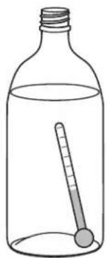
CHECKING PRODUCT TEMPERATURE
natural_image
Simple line drawing of a bottle with a thermometer inside, no text or symbols presentTo check the actual product temperature in the unit:
- Partially fill a plastic (nonbreakable) bottle with water.
- Insert an accurate thermometer.
- Tighten the bottle cap securely.
- Place the bottle in the desired area for 24 hours.
- Avoid opening the unit during the testing period.
- After 24 hours, check the temperature of the water. If required, adjust the temperature control in a small increment (see CONTROL OPERATION).
Causes which affect the internal temperatures of the cabinet include:
• Temperature setting.
- Ambient temperature where installed.
• Installation in direct sunlight or near a heat source.
- The number of door openings and the time the door is open.
- The time the internal light is illuminated. (This mainly affects product on the top rack or shelf.)
• Obstruction of front grille or condenser.
SAFETY • INSTALLATION & INTEGRATION • OPERATING INSTRUCTIONS • MAINTENANCE • SERVICE
Warranty
U-LINE CORPORATION LIMITED WARRANTY
-
U-Line Corporation ("U-Line") warrants each U-Line product to be free from defects in materials and workmanship for a period of one year (two years on Modular 3000 Series) from the date of purchase. U-Line further warrants the sealed system (consisting of the compressor, condenser, evaporator, hot gas bypass valve, dryer, and connecting tube) in each U-Line product to be free from defects in materials and workmanship for a period of five years from the date of purchase.
-
During the initial one year warranty period (two years on Modular 3000 Series) for all U-Line products U-Line shall: (1) repair any product or replace any part of a product; and (2) for all Marine, RV, and Domestic U-Line products sold and serviced in the United States (including Alaska and Hawaii) and Canada, U-Line shall be responsible for the labor costs performed by a U-Line authorized service company, incurred in connection with the replacement of any defective part. During years two through five of the warranty period for the sealed system, U-Line shall: (1) at U-Line's option repair or replace any part of the sealed system; and (2) for all Marine, RV, and Domestic U-Line products sold and serviced in the United States (including Alaska and Hawaii) and Canada, U-Line shall be responsible for the labor costs incurred in connection with the replacement of any defective part of the sealed system. All other charges, including transportation charges for replacements under this warranty and labor costs not specifically covered by this warranty, shall be the responsibility of the purchaser. This warranty extends only to the original purchaser of the U-Line product. The Product Registration Card included with the product should be promptly completed by you and mailed back to U-Line, or you can register on-line at www.u-lineservice.com.
-
The warranty listed above does not apply to floor display models. The warranty for these models shall be 30 days from the date of retail purchase and only if U-Line's Product Registration Card included with the
unit is completed and mailed back or electronically submitted to U-Line. This 30 day warranty does not apply to cosmetic damages. A proof of purchase may be required.
-
The following conditions are excluded from this limited warranty: use of cleaners other than the recommended stainless steel cleaners and U-Line Clear Ice Maker cleaner; installation charges; damages caused by disasters or acts of God, such as fire, floods, wind, and lightning; damages incurred or resulting from shipping, improper installation, unauthorized modification, or misuse/abuse of the product; customer education calls; food loss and spoilage; door and water level adjustments (except during the first 30 days from the date of installation); defrosting the product; adjusting the controls; door reversal; and cleaning the condenser.
-
U-Line products are designed to operate in ambient temperatures between 50^ F and 100^ F unless otherwise noted in the product manual. Exposure to temperatures outside this range may cause degradation of performance and issues, such as lower ice production or spoiled contents, that are not covered under the terms of this warranty as a result of that exposure. U-Line product may not be subjected to temperatures below 40^ F without following the winterization and vacation shutdown procedures in the user guide.
-
U-Line's Outdoor Limited Warranty, set forth in this Paragraph 6 shall apply to U-Line models deemed suitable for outdoor use by Underwriters Laboratory ("UL") as noted in the U-Line Product Catalog, U-Line's website, and/or on the serial tag located inside the product.
A. Outdoor product may come into contact with rain by virtue of outdoor use. Exposure to other sources of water shall also cause this warranty to be void, including flooding of the area in proximity of the unit greater than 1/8" deep in water, hurricanes, splashing
SAFETY • INSTALLATION & INTEGRATION • OPERATING INSTRUCTIONS • MAINTENANCE • SERVICE
of pool water, or directing a spray from a hose or similar device into and around the unit.
-
If a product defect is discovered during the applicable warranty period, you must promptly notify either U-Line at 8900 N. 55th Street, Milwaukee, Wisconsin 53223 USA or at +1.800.779.2547 or the dealer from whom you purchased the product. In no event shall such notification be received later than 30 days after the expiration of the applicable warranty period. U-Line may require that defective parts be returned, at your expense, to U-Line's factory in Milwaukee, Wisconsin, for inspection. Any action by you for breach of warranty must be commenced within one year after the applicable warranty period.
-
THIS LIMITED WARRANTY IS IN LIEU OF ANY AND ALL OTHER WARRANTIES, EXPRESS OR IMPLIED, INCLUDING ANY IMPLIED WARRANTY OF MERCHANTABILITY OR IMPLIED WARRANTY OF FITNESS FOR A PARTICULAR PURPOSE, ALL OF WHICH ARE DISCLAIMED. U-Line's sole liability, and your exclusive remedy, under this warranty is set forth in the paragraphs above. U-Line shall have no liability whatsoever for any incidental, consequential, or special damages arising from the sale, use, or installation of the product or from any other cause whatsoever, whether based on warranty (express or implied) or otherwise based on contract, tort, or any other theory of liability.
Some states do not allow limitations on how long an implied warranty lasts or the exclusion or limitation of incidental or consequential damages, so the above limitations may not apply to you. This warranty gives you specific legal rights, and you may also have other rights which vary from state to state.
Warranty 6/2014 Rev.G
- Contents
- Safety
- Service
- Installation
- Operating Instructions
- Maintenance
- WELCOME TO U-LINE
- PRODUCT INFORMATION
- PROPERTY DAMAGE / INJURY CONCERNS
- SERVICE INFORMATION
- GENERAL INQUIRIES
- SERVICE & PARTS ASSISTANCE
- CONNECT WITH US
- Safety and Warning
- NOTICE
- SAFETY ALERT DEFINITIONS
- DANGER
- WARNING
- CAUTION
- Disposal and Recycling
- Environmental Requirements
- Electrical
- Cutout Dimensions
- PREPARE SITE
- Side-by-Side Installation
- Side-by-Side Installation with Bracket
- Anti-Tip Bracket
- General Installation
- LEVELING INFORMATION
- INSTALLATION TIP
- Removing the grille
- Installing the grille
- Door Swing
- Door Stop
- Door Adjustments
- DOOR ALIGNMENT AND ADJUSTMENT
- To align and adjust the door:
- REVERSING THE DOOR
- TO REVERSE THE DOOR
- Remove grille:
- Remove door:
- Prepare door for reinstallation:
- SHIFTING WINE RACK SPACERS (OPTIONAL)
- Align and adjust the door:
- Install grille:
- Wood Trim Finishing
- Free Standing Kit
- To install the kit:
- First Use
- MECHANICAL DIAL CONTROL
- Airflow and Product Loading
- U-Line Wine Guide
- WINE SELECTIONS SUGGESTIONS
- Matching Food and Wine
- A Toast to Wine Truths
- The Cork: A Mystery on Its Own
- IDEAL WINE STORAGE CONSIDERATIONS
- Wine Captain ® Models - A Touch of Elegance
- Recommended Wine Storage
- Interior Shelves
- REMOVING AND INSTALLING INTERIOR SHELVES
- Insert the shelves as follows:
- Cleaning
- EXTERIOR CLEANING
- Vinyl Clad (Black or White)
- Stainless Models
- Do not clean with steel wool pads.
- Do not use stainless steel cleaners polishes on any glass surfaces.
- Do not use cleaners not specifically intended for stainless steel on stainless surfaces (this includes glass, tile and counter cleaners).
- Using abrasive pads such as Scotchbrite™ will cause the graining in the stainless steel to become blurred.
- Integrated Models
- INTERIOR CLEANING
- DEFROSTING
- To defrost:
- Cleaning Condenser
- INTERVAL - EVERY SIX MONTHS
- Wine Rack Installation
- To remove rack from the cabinet:
- To insert rack in the cabinet:
- Light Replacement
- Extended Non-Use
- VACATION/HOLIDAY, PROLONGED SHUTDOWN
- WINTERIZATION
- Troubleshooting
- BEFORE CALLING FOR SERVICE
- IF SERVICE IS REQUIRED
- TROUBLESHOOTING GUIDE
- ELECTROCUTION HAZARD. Never attempt to repair or perform maintenance on the unit before disconnecting the main electrical power.
- To check the actual product temperature in the unit:
- Warranty
- U-LINE CORPORATION LIMITED WARRANTY
Brand : U-Line
Model : 1024BEVS-00A
Category : Wine cellar