3036BVWCS-13A - Wine cellar U-Line - Free user manual and instructions
Find the device manual for free 3036BVWCS-13A U-Line in PDF.


| Product Type | Wine Cellar |
| Brand | U-Line |
| Model | 3036BVWCS-13A |
| Series | 3000 Series |
| Unit Width | 36" (900 mm) |
| Integrated Panel Width (per door) | 17-1/2" (445 mm) |
| Integrated Panel Depth | 28-13/16" (732 mm) |
| Max Panel Weight | 20 lbs (10 kg) |
| Grille (Plinth Strip) Height Range | 3-5/16" (84 mm) to 4-5/16" (110 mm) |
| Grille Horizontal Extension Max | 1-1/2" (38 mm) |
| Recommended Panel Thickness | 1/4" (6 mm) to 3/8" (9 mm) |
| Minimum Floor Clearance for Ventilation | 1" (25 mm) |
| Door Panel Screw Size | #6 x 1-1/2" (38 mm) |
| Screw Pilot Hole Depth | 1/2" (12 mm) |
| Grille Lock Screw Allen Wrench Size | 7/64" |
| Handleless Insert Material | Wood, 1/8" (3 mm) thick |
| Handleless Insert Dimensions (36" unit) | 17-1/2" x 3-1/2" (445 mm x 89 mm) per door |
| Customer Care Contact | +1.800.779.2547 |
| Service & Parts Email | onlineservice@u-line.com / onlineparts@u-line.com |
| Designed & Assembled | Milwaukee, WI, USA |
Frequently Asked Questions - 3036BVWCS-13A U-Line
User questions about 3036BVWCS-13A U-Line
0 question about this device. Answer the ones you know or ask your own.
Ask a new question about this device
Download the instructions for your Wine cellar in PDF format for free! Find your manual 3036BVWCS-13A - U-Line and take your electronic device back in hand. On this page are published all the documents necessary for the use of your device. 3036BVWCS-13A by U-Line.
USER MANUAL 3036BVWCS-13A U-Line
Tip: Click on any section below to jump directly there
Contents
Intro
Installation
Integrated Panel Dimensions
Integrated Grille / Plinth Dimensions
Integrated Panel Installation
Grille / Plinth Installation
WELCOME TO U-LINE
Congratulations on your U-Line purchase. Your product comes from a company with over five decades and three generations of premium modular ice making, refrigeration, and wine preservation experience. U-Line continues to be the American leader, delivering versatility and flexibility for multiple applications including residential, light commercial, outdoor and marine use. U-Line's complete product collection includes modular Wine Captain® Models, Beverage Centers, Clear Ice Machines, Crescent Ice Makers, Glass & Solid Door Refrigerators, Drawer Models, Freezers, and Combo® Models.
U-Line has captivated those with an appreciation for the finer things with exceptional functionality, style, inspired innovations and attention to even the smallest details. We are known and respected for our unwavering dedication to product design, quality and selection. U-Line is headquartered in Milwaukee, Wisconsin with a west coast office located in Laguna Beach, California and European support in Dublin, Ireland. U-Line has shipped product to five continents for over two decades and is proud to have the opportunity to ship to you.
PRODUCT INFORMATION
Looking for additional information on your product? User Guides, Quick Reference Guides, CAD Drawings, Compliance Documentation, and Product Warranty information are all available for reference and download at u-line.com under Documentation.
PROPERTY DAMAGE / INJURY CONCERNS
In the unlikely event property damage or personal injury is suspected related to a U-Line product, please take the following steps:
- U-Line Customer Care must be contacted immediately at +1.800.779.2547.
- Service or repairs performed on the unit without prior written approval from U-Line is not permitted. If the unit has been altered or repaired in the field without prior written approval from U-Line, claims will not be eligible.
SERVICE INFORMATION
Answers to Customer Frequently Asked Questions are available at u-line.com under Customer Care or you may contact our Customer Care group directly, contact information below.
GENERAL INQUIRIES
U-Line Corporation
8900 N. 55th Street
Milwaukee, Wisconsin 53223 USA
Monday - Friday 8:00 am to 4:30 pm CST
T: +1.414.354.0300
F: +1.414.354.7905
Email: sales@u-line.com
u-line.com
SERVICE & PARTS ASSISTANCE
Monday - Friday 8:00 am to 5:30 pm CST
T: +1.800.779.2547
F: +1.414.354.5696
Service Email: onlineservice@u-line.com
Parts Email: onlineparts@u-line.com
CONNECT WITH US
f Twitter g+ YouTube in blog
Designed, engineered and assembled in WI, USA
SAFETY • INSTALLATION & INTEGRATION • OPERATING INSTRUCTIONS • MAINTENANCE • SERVICE
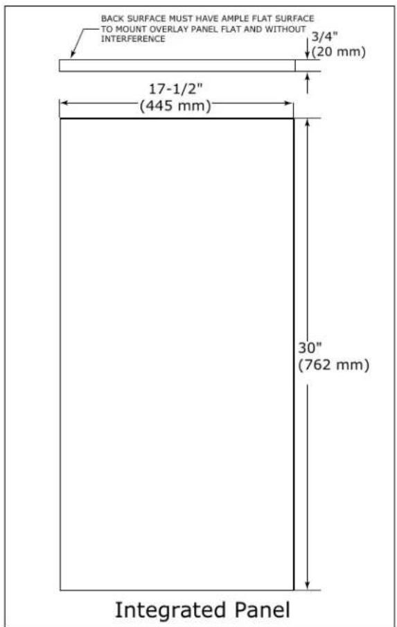
Integrated Panel Dimensions
INTEGRATED PANEL
NOTICE
Due to differences in surrounding cabinetry the panel may not perfectly align with door. The procedure below is designed to provide a finished overlay panel that seamlessly integrates with surrounding cabinetry.
PANEL PREPARATION
A full integrated door panel completely covers the door frame and provides a built-in appearance.
NOTICE
The door panel must not weigh more than 20 lbs (10 kg).
It is important to ensure that all drilled holes are drilled to the correct depth in order to avoid splits in the wood when hardware is installed.
- Cut the panels to the dimensions listed in the diagram below.
- Optional: Stain or Finish panel to desired stain or color. Be sure to closely follow the instructions provided by the manufacturer.
- Optional: Install handles and hardware.
NOTICE
When applying an integrated panel to a unit, ensure that both sides are finished in order to prevent warping. In some panel installations, the panel may be visible through the glass while the door is open.
Integrated Panel Dimensions
SAFETY • INSTALLATION & INTEGRATION • OPERATING INSTRUCTIONS • MAINTENANCE • SERVICE
Handleless Integrated Door Panel
The following procedure is designed to provide a finished, handleless solid panel for an 18" (450 mm) door that seamlessly integrates with its surrounding cabinetry. Prepare two 18" (450 mm) overlays for 36" (900 mm) units.
NOTE: Many cabinet manufacturers provide a ready solution for a handle-less, integrated design that can be easily applied to your U-Line 3000 Series model. Consult your cabinet manufacturer for applicable design and installation details. The cabinet manufacturer's solution to this design and integration detail will often result in an integrated panel solution wherein the size of the panel may result in a height dimension taller than what we specify. This can be achieved provided the additional height is positioned above the appliance door.
NOTICE
The integrated panel aligns with the surrounding cabinetry and, due to differences in cabinetry, may not align perfectly with the door.
The appliance will need up to 34-1/2" (876 mm) to the underside of the counter to leave room for leveling adjustments.
A single prepared panel with insert must not weigh more than 20 lbs (10 kg).
Integrated Panel Preparation
- Cut the main panels to the dimensions below. For details, see the drawings on the next page.
| Unit width | Panel width | Panel depth |
| 36" (900 mm) | 17-1/2" (445 mm) | 28-13/16" (732 mm) |
-
Create the top design for the handleless feature and the 1/8" (3 mm) notch for the insert(s) indicated on the Top Detail drawing, on the next page.
-
Prepare the insert(s) that will back up the handleless design. Wooden Insert - Cut 1/8" (3 mm) thick wooden insert(s) to the appropriate dimensions below.
| Unit width | Insert width | Insert depth |
| 36" (900 mm) | 17-1/2" (445 mm) | 3-1/2" (89 mm) |
*Two 18" (450 mm) inserts are required for 36" (900 mm) units.
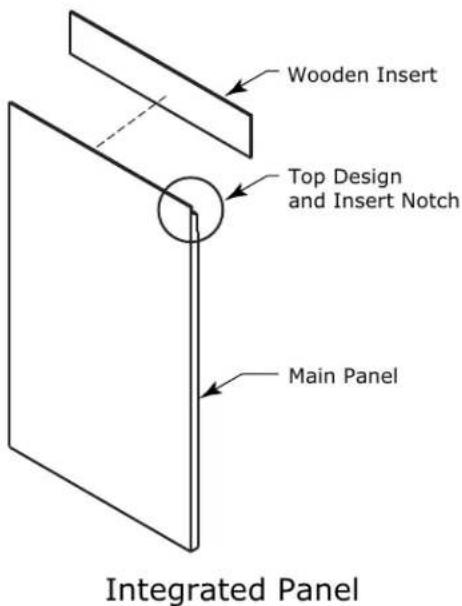
- Optional: Stain or finish panel and wooden insert to desired stain or color. Be sure to closely follow the instructions provided by the manufacturer.
NOTICE
If finishing panel or wooden insert, all sides must be finished to prevent warping.
- Attach the insert to the panel / frame. Wood glue or equivalent adhesive should be used to attach insert to panel.
SAFETY • INSTALLATION & INTEGRATION • OPERATING INSTRUCTIONS • MAINTENANCE • SERVICE
Attach Wooden Insert
SAFETY • INSTALLATION & INTEGRATION • OPERATING INSTRUCTIONS • MAINTENANCE • SERVICE
Handleless Integrated Panel Dimensions
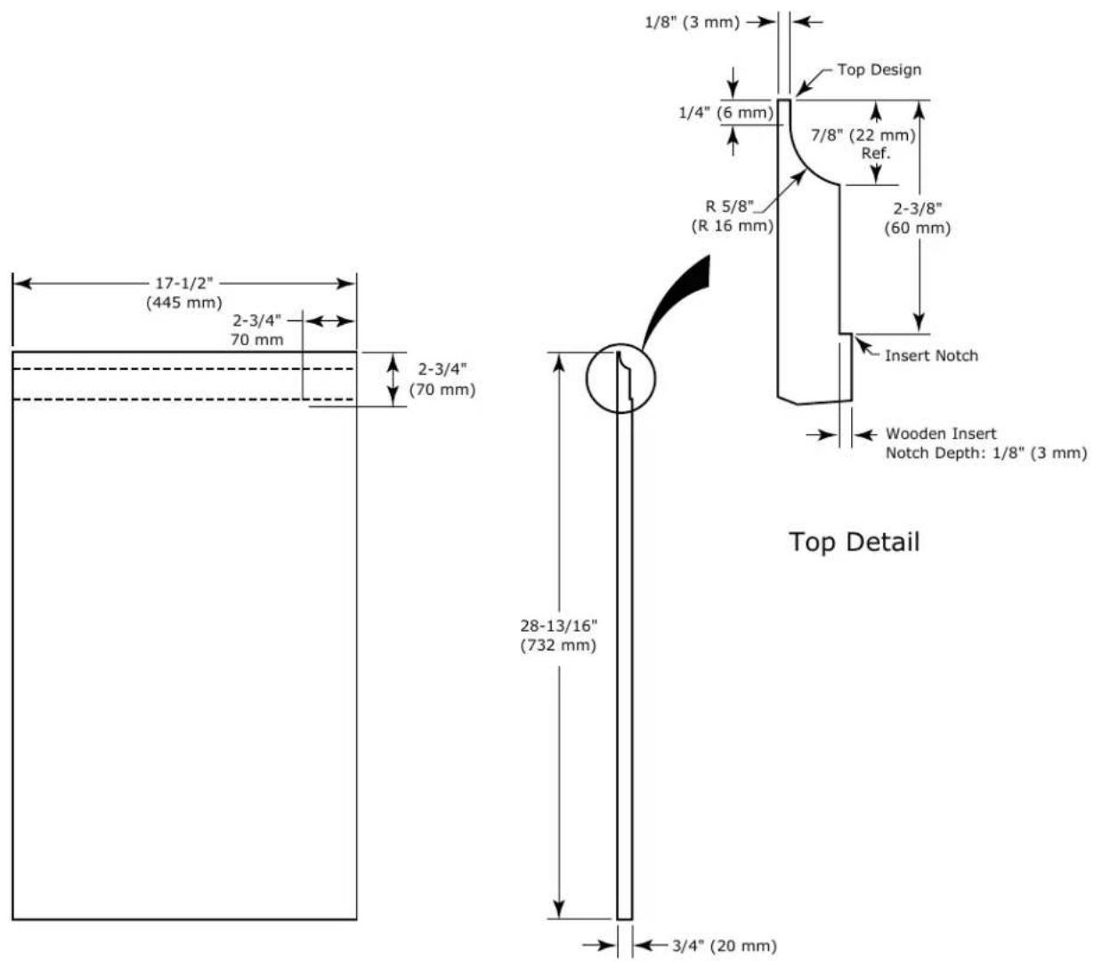
Wooden Insert Dimensions

SAFETY • INSTALLATION & INTEGRATION • OPERATING INSTRUCTIONS • MAINTENANCE • SERVICE
Extended Integrated Panel
NOTICE
Due to differences in surrounding cabinetry the panel may not perfectly align with door. The procedure below is designed to provide a finished panel that seamlessly integrates with surrounding cabinetry.
Panel Preparation
An extended integrated panel can be used to maintain alignment with an adjacent extended cabinet height or a reduced toe-kick/grille application.
- Cut the panels to the dimensions listed in the diagram on the next page.
- Optional: Stain or Finish panel to desired stain or color. Be sure to closely follow the instructions provided by the manufacturer.
- Optional: Install handles and hardware.
NOTICE
The door panel must not weigh more than 20 lbs (10 kg).
It is important to ensure that all drilled holes are drilled to the correct depth in order to avoid splits in the wood when hardware is installed.
Appliance will need up to 34-1/2" (876.3 mm) to the under side of the counter to leave room for leveling adjustments.
When applying an integrated panel to a unit, ensure that both sides are finished in order to prevent warping. In some installations, the panel may be visible through the glass while the door is open.
SAFETY • INSTALLATION & INTEGRATION • OPERATING INSTRUCTIONS • MAINTENANCE • SERVICE
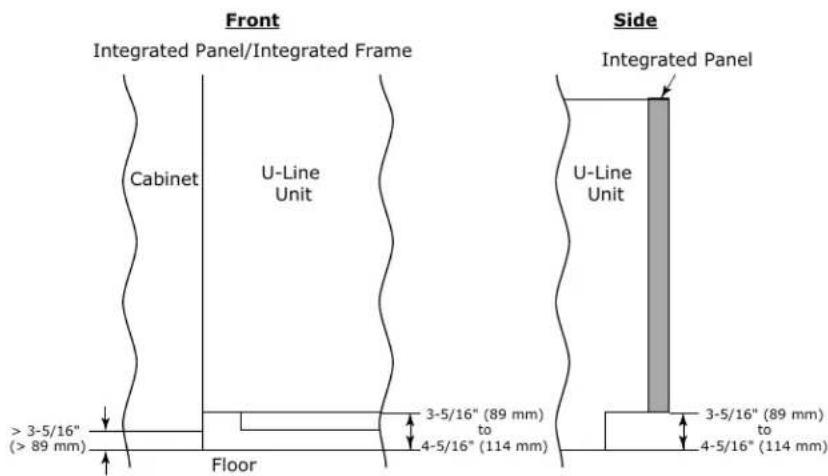
Front
Extended Integrated Panel/Extended Integrated Frame
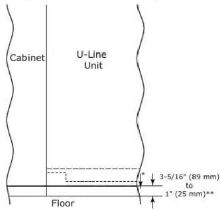
Side Integrated Panel
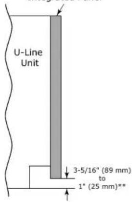
* Panel can extend beyond the door frame.
**A minimum of 1" (25 mm) from the floor is required for proper ventilation.
SAFETY • INSTALLATION & INTEGRATION • OPERATING INSTRUCTIONS • MAINTENANCE • SERVICE
Extended Integrated Panel Dimensions
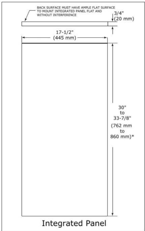
* A minimum of 1" (25 mm) is required from the floor to the bottom of the extended integrated panel/frame for proper ventilation.
SAFETY • INSTALLATION & INTEGRATION • OPERATING INSTRUCTIONS • MAINTENANCE • SERVICE
Integrated Grille - Plinth Dimensions
The 3000 series grille (plinth strip/base fascia) is fully adjustable and can be set to match your surrounding furniture dimensions. In addition to it's adjustability, an integrated grille may also be installed to truly provide a seamless appearance.
PREPARE AND INSTALL INTEGRATED GRILLE (PLINTH STRIP/BASE FASCIA)
- Use the dimensions provided in the diagram to cut and shape your integrated grille (plinth strip/base fascia) panel. Recommended panel thickness is between 1/4" (6 mm) and 3/8" (9 mm). Height will vary from 3-5/16" (84 mm) to 4-5/16" (110 mm) based on your grille (plinth strip/base fascia) height.
- Finish or stain your grille (plinth strip/base fascia) panel to match your surrounding furniture. Finish front, back and edges to prevent warping. Carefully follow the manufacturer's recommendations for finish application and cure times.
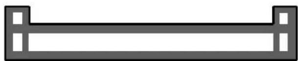
- Apply double sided tape to the backside of the integrated grill (plinth strip/base fascia). Use the diagram below for reference. U-Line recommends 3M ^TM VHB ^TM tape, a high strength bonding tape.
Apply Tape To Shaded Area
natural_image
Simple black rectangular frame with rounded corners and a horizontal bar (no text or symbols)-
Remove backing paper from double sided tape.
-
Carefully align grille (plinth strip/base fascia) over integrated panel and press into position.
INTEGRATED GRILLE (PLINTH STRIP/BASE FASCIA) DIMENSIONS

SAFETY • INSTALLATION & INTEGRATION • OPERATING INSTRUCTIONS • MAINTENANCE • SERVICE
Integrated Panel Installation
-
Fully open door/drawer.
-
Starting at corner, pull gasket away from door/drawer.
-
Continue to pull gasket free from gasket channel.
-
Upon removal, lay gasket down on a flat surface.
NOTICE
If the door/drawer houses the display, make certain the display cable remains securely seated in the inner door channel, see below.
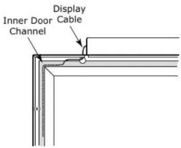
- The panel should be aligned with the outside edge (opposite the hinge, if equipped) and high enough to align with the highest point in the door/drawer.
Align Top Of Panel With Highest Point Of Door/Drawer
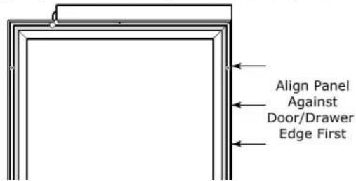
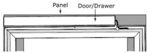
NOTICE
Due to differences in floor construction or surrounding cabinetry, the panel may not sit flush with the top of the door/drawer.
-
Secure integrated panel to door/ drawer using clamps. A robust tape may also be used. U-Line recommends the use of bar clamps to secure the panel to the door/drawer. If using tape, be certain the tape will not damage panel finish upon removal.
-
Using a 7/64"
(3 mm) drill bit, drill 6 pilot holes into the wood panel
1/2" (12 mm) deep using the holes in the door/drawer frame as a guide.
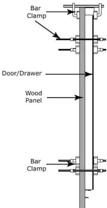
NOTICE
It is important to ensure that all drilled holes are drilled to the correct depth in order to avoid splits in the wood when hardwood is installed.
- Locate 6 of the #6x 1-1/2" (38 mm) screws provided with your unit.
SAFETY • INSTALLATION & INTEGRATION • OPERATING INSTRUCTIONS • MAINTENANCE • SERVICE
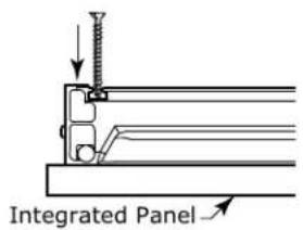
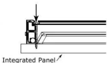
- Using a Phillips screwdriver, place one screw into each of the 6 pilot holes and screw down. Do not overtighten screws.
- Be sure the screws force their way past the opening on the gasket channel and sit flush against the bottom of the channel.
- Remove clamps from door/drawer.
NOTICE
If panel requires additional adjustment after removing clamps, slightly loosen each screw and adjust panel as necessary. Tighten screws upon completion.
Do not overtighten screws, bulges in plastic frame might be visible if tightened too much.
- Starting at the corners, re-install the gasket into the gasket channel in the frame. Make sure the gasket is fully seated. This may take some force.
SAFETY • INSTALLATION & INTEGRATION • OPERATING INSTRUCTIONS • MAINTENANCE • SERVICE
Grille - Plinth Installation
REMOVING AND INSTALLING GRILLE (PLINTH STRIP/BASE FASCIA)
Disconnect electrical current to the unit before removing the grille (plinth strip/base fascia).
When using the unit, the grille (plinth strip/base fascia) must be installed.
Edges of sheet metal may be sharp.
Removing the grille (plinth strip/base fascia)
-
Disconnect electrical current to unit.
-
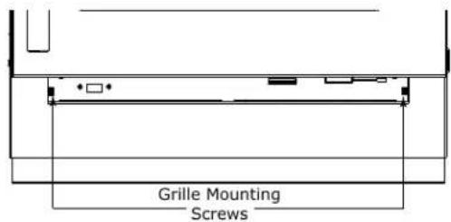
Using the included 7/64" Allen wrench, loosen (but do not remove) both grille (plinth strip/base fascia) lock screws. See below.
-
Gently pull grille (plinth strip/base fascia) away from unit until it stops.
-
Push grille (plinth strip/base fascia) rails towards the center of the unit to lift rails off lock screws.
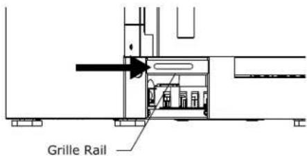
- Pull grille (plinth strip/base fascia) free from unit.
Installing the grille (plinth strip/base fascia)
-
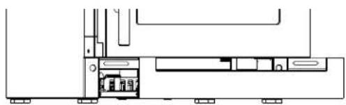
Align slots in grille (plinth strip/base fascia) rail with screw heads in base of unit
-
Push grille (plinth strip/base fascia) rails towards the center of the unit and set rails over screw head.
-
Slide grille (plinth strip/base fascia) into position. Using included 7/64" Allen wrench tighten grille (plinth strip/base fascia) lock screws.
natural_image
Architectural cross-section diagram of a building facade with internal components and structural elements (no text or labels)ADJUSTING GRILLE (PLINTH STRIP/BASE FASCIA)
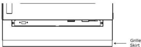
The grille (plinth strip/base fascia) has an automatic vertical plane adjustment and can also be adjusted on its horizontal plane as well. To adjust your grille (plinth strip/base fascia) to match your surrounding furniture, follow the instructions below.
-
Loosen, but do not remove, the lock screws on the inside of the grille (plinth strip/base fascia) rails. Lock screws are located on the inside of each grille (plinth strip/base fascia) rail.
-
The grille (plinth strip/base fascia) can be extended horizontally by pulling out a maximum of 1-1/2" (38 mm). Do not exceed 1-1/2" (38 mm). Secure the lock screws after adjusting.
-
The grille (plinth strip/base fascia) skirt may be manually adjusted to the height of your floor. Simply raise or lower the skirt as needed.
- Contents
- Installation
- WELCOME TO U-LINE
- PRODUCT INFORMATION
- PROPERTY DAMAGE / INJURY CONCERNS
- SERVICE INFORMATION
- GENERAL INQUIRIES
- SERVICE & PARTS ASSISTANCE
- CONNECT WITH US
- Integrated Panel Dimensions
- INTEGRATED PANEL
- NOTICE
- PANEL PREPARATION
- Handleless Integrated Door Panel
- Integrated Panel Preparation
- Extended Integrated Panel
- Integrated Grille - Plinth Dimensions
- PREPARE AND INSTALL INTEGRATED GRILLE (PLINTH STRIP/BASE FASCIA)
- Integrated Panel Installation
- Grille - Plinth Installation
- REMOVING AND INSTALLING GRILLE (PLINTH STRIP/BASE FASCIA)
- Removing the grille (plinth strip/base fascia)
- Installing the grille (plinth strip/base fascia)
- ADJUSTING GRILLE (PLINTH STRIP/BASE FASCIA)
Brand : U-Line
Model : 3036BVWCS-13A
Category : Wine cellar