
AP9520TH - Temperature Controller APC - Free user manual and instructions
Find the device manual for free AP9520TH APC in PDF.


| Product Type | Temperature and Humidity Sensor with Display |
| Brand | APC |
| Model | AP9520TH |
| Dimensions (H x W x D) | 3.9 x 1.7 x 1.1 in (10.0 x 4.35 x 2.75 cm) |
| Weight | 2.7 oz (76 g) |
| Operating Voltage | 24 VDC nominal |
| Operating Current | 10 mA (max) |
| Temperature Accuracy | ±1.8°F (1.0°C) |
| Humidity Accuracy | ±3.0% RH @ 25°C |
| Operating Temperature Range | -4 to 140°F (-20 to 60°C) |
| Storage Temperature Range | -40 to 176°F (-40 to 80°C) |
| Operating Elevation | 0 to 10,000 ft (0 to 3000 m) |
| Storage Elevation | 0 to 50,000 ft (0 to 15000 m) |
| Display | Scrolling digital display (temperature and humidity) |
| Sensor Type | Combined temperature and humidity |
| Installation Method | Screws or hook-and-loop fasteners |
| Communication | A-Link via DIP switches (CAT 5 cable) |
| Approvals / Certifications | AS/NZS CISPR 22 Class A, CE, EN 55022 Class A, EN 55024, FCC Part 15 Class A, ICES-003, VCCI |
| Included Accessories | Terminator (0W04161), 4 screws, 2 hook-and-loop fasteners |
| Spare Parts | Terminator (0W04161) available |
Frequently Asked Questions - AP9520TH APC
User questions about AP9520TH APC
0 question about this device. Answer the ones you know or ask your own.
Ask a new question about this device
Download the instructions for your Temperature Controller in PDF format for free! Find your manual AP9520TH - APC and take your electronic device back in hand. On this page are published all the documents necessary for the use of your device. AP9520TH by APC.
USER MANUAL AP9520TH APC
Temperature and Humidity Sensor Installation Sheet
Inventory
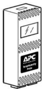
Temperature and Humidity Sensor with Display or Temperature Sensor with Display (1)

6 × 3/4-in Phillips self-tapping screws (4)

Hook-and-loop fasteners (2)
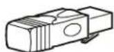
Terminator (1)
Install the sensor
- Find a suitable location to mount the sensor, such as an area that contains mixed, moving air.

Note: Avoid installing the sensor near an area that could cause an inaccurate reading, such as near air ducts, windows, exterior walls, or room entrances.
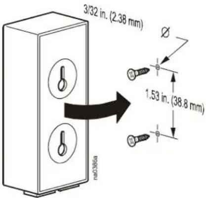
- Mount the sensor using screws or hook-and-loop fasteners:
- Using screws: Mark and drill two holes, 3/32 in (2.38 mm) in diameter and 1.53 in (38.8 mm) apart.

Warning: Before drilling, check for unexposed wiring behind the drilling surface.
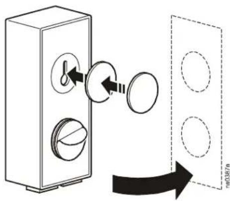
- Using hook-and-loop fasteners:
Clean the mounting surface so that it is free of dust, oils, and moisture. Install the sensor using both hoop-and-loop fasteners. Hold them in place for five seconds to ensure a firm adhesion.
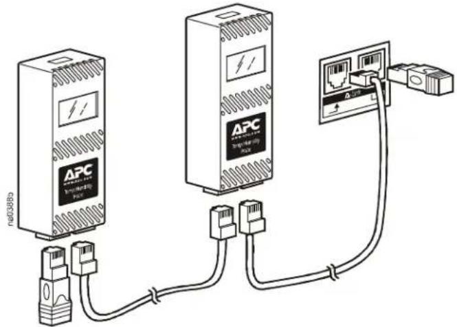
- Route a cable from the sensor to the device that will monitor the sensor. When using more than one sensor: Route a cable from one sensor to the next. Each connection on the sensor should have either a CAT 5 cable or a terminator (0W04161) (provided).
Set the A-Link address
Set the DIP switches on each sensor to a unique A-Link address.
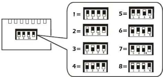

See the documentation provided with the monitoring device for A-Link addresses. Each sensor must be set with a unique A-Link address. Some addresses are reserved for use by the monitoring device. The addresses for sensors will vary depending on the monitoring device to which they are connected.
Screen menus
At three-second intervals, the display scrolls through two screens (for AP9520T) or three screens (for AP9520TH).
Specifications
Electrical
| Operating Voltage | 24 VDC nominal |
| Operating Current 10 mA (max) | |
| Temperature Accuracy* ± 1.8°F (1.0°C) | |
| Temperature Drift* ± 0.36°F (0.2°C)/over life of unit | |
| Humidity Accuracy (AP9520TH) * ± 3.0% RH @ 25°C | |
| Humidity Drift (AP9520TH) * ± 1.0% RH/5 years | |
| * In airflow of >100 ft/min. | |
| Physical | |
| Size (H × W × D) 3.9 × 1.7 × 1.1 in | 10.0 × 4.35 × 2.75 cm |
| Weight 2.7 oz (76 g) | |
| Environmental | |
| Elevation | |
| Operating 0 to 10,000 ft (0 to 3000 m) | |
| Storage 0 to 50,000 ft (0 to 15 000 m) | |
| Temperature | |
| Operating -4 to 140°F (-20 to 60°C) | |
| Storage -40 to 176°F (-40 to 80°C) | |
| Approvals | |
| EMC Verification | AS/NZS CISPR 22 (C-Tick) Class A, CE, EN 55022 Class A, EN 55024, FCC Part 15 Class A, ICES-003, VCCI |
Radio Frequency Interference

Warning: Changes or modifications to this unit not expressly approved by the party responsible for compliance could void the user's authority to operate this equipment.
USA—FCC
This equipment has been tested and found to comply with the limits for a Class A digital device, pursuant to part 15 of the FCC Rules. These limits are designed to provide reasonable protection against harmful interference when the equipment is operated in a commercial environment. This equipment generates, uses, and can radiate radio frequency energy and, if not installed and used in accordance with this user manual, may cause harmful interference to radio communications.
Operation of this equipment in a residential area is likely to cause harmful interference. The user will bear sole responsibility for correcting such interference.
Canada—ICES
This Class A digital apparatus complies with Canadian ICES-003.
This is a Class A product based on the standard of the Voluntary Control Council for Interference by Information Technology Equipment (VCCI). If this equipment is used in a domestic environment, radio disturbance may occur, in which case, the user may be required to take corrective actions.
Entire contents copyright 2006 American Power Conversion Corporation. All rights reserved.
Reproduction in whole or in part without permission is prohibited. APC, the APC logo, and InfraStruXure are trademarks of American Power Conversion Corporation. All other trademarks, product names, and corporate names are the property of their respective owners and are used for informational purposes only.
Brand : APC
Model : AP9520TH
Category : Temperature Controller