IS2 - Pregnant SONANCE - Free user manual and instructions
Find the device manual for free IS2 SONANCE in PDF.


| Product Type | Invisible in-wall/in-ceiling speaker |
| Speaker Configuration | 2-way (tweeter and woofer) |
| Tweeter Driver | 4 sq. in (27 sq. cm) planar diaphragm, 1" (25mm) voice coil |
| Woofer Driver | 50 sq. in (320 sq. cm) planar diaphragm, 1" (25mm) voice coil |
| Frequency Response | 50 Hz - 20 kHz ±3 dB |
| Impedance | 8 ohms (nominal) |
| Power Handling | 80 Watts RMS |
| Sensitivity | 88 dB (1W/1 meter) |
| Dispersion | 170° hemispherical up to 10 kHz |
| Cutout Dimensions (Without Enclosure) | 16-1/8" x 12-1/8" x 2" (409.5mm x 307mm x 51mm) |
| Cutout Dimensions (With Enclosure) | 16-1/8" x 12-1/8" x 3-13/16" (409.5mm x 307mm x 97mm) |
| Shipping Weight | 12 lbs (5.5 kg) per pair |
| Finish | Paper surface ready for texture and paint |
| Overload Protection | Two independent self-resetting gel switches (low and high) |
| Recommended Amplifier Power | Up to 100 watts per channel |
| Installation Type | New or existing construction (wall or ceiling) |
| Minimum Mounting Height (on walls) | 7 ft (2.1 m) from floor |
| Wire Gauge Requirement | Use 14-12 AWG for runs up to 100 ft to minimize resistance |
| Finishing Instructions | Use 5-minute setting joint compound, mesh tape, and multiple coats; total buildup ≤ 1/8" (3mm) |
| Warranty | 15 years limited (transferable only to first end-user) |
| Optional Accessories | Enclosure (part #92969) for IS2; Space Saver (part #92722) for new construction |
Frequently Asked Questions - IS2 SONANCE
User questions about IS2 SONANCE
0 question about this device. Answer the ones you know or ask your own.
Ask a new question about this device
Download the instructions for your Pregnant in PDF format for free! Find your manual IS2 - SONANCE and take your electronic device back in hand. On this page are published all the documents necessary for the use of your device. IS2 by SONANCE.
USER MANUAL IS2 SONANCE
SONANCE INVISIBLE SERIES SPEAKER INSTALLATION
TABLE OF CONTENTS
INTRODUCTION: INVISIBLE SPEAKERS 2-3
SPECIFICATIONS 2-3
IS SPEAKER INSTALLATION DETAIL VIEW 4
WIRE GAUGE CHART 4
NEW CONSTRUCTION 5-8
EXISTING CONSTRUCTION 9-11
FINISHING INSTRUCTIONS 12-16
NOTES 17
WARRANTY 18
INTRODUCTION
SONANCE offers what few have before: the ability to contribute to brilliant architecture and genius design by removing an element. By removing dated protruding fixtures and other traditional wall-mounted necessities, and replacing them with flush fixtures, the products bow out of the spotlight and allow the artistic structure to take center stage. SONANCE INVISIBLE SERIES offers audiophile quality and ease of installation to any design project.
SONANCE INVISIBLE SERIES
natural_image
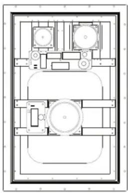
Architectural floor plan showing room layouts and structural elements (no text or labels)IS4
The new benchmark for invisible speakers. The IS4 features state of the art planar diaphragm technology. The rigid metal frame and optional enclosure make this speaker the best sounding fully concealed speaker in the world.
SPECIFICATIONS
Tweeter 4 sq. in (27 sq. cm) planar diaphragm, driven by a 1" (25mm) voice coil
Midrange 17 sq. in (110 sq. cm) planar diaphragm, driven by a 1" (25mm) voice coil
Woofer 113 sq. in (732 sq. cm) planar diaphragm, driven by a 2" (50mm) voice coil
Frequency Response 40Hz - 20kHz ±3dB
Impedance 8 ohms nominal
Power Handling 100 watts RMS
Sensitivity 90dB (1W/1 meter)
Dispersion 170° hemispherical up to 10kHz
Finish Paper surface ready for texture and paint
Overload Protection Three independent self-resetting gel switches (low, mid and high)
Cutout Dims
Without Enclosure (WxHxD) 16-1/8" x 24-1/8" x 2" (409mm x 613mm x 51mm)
Cutout Dims -
With Enclosure (WxHxD) 16-1/8" x 24-1/8" x 3-13/16" (409mm x 613mm x 97mm)
Shipping Weight 25 lbs (11.25 kg) pair
natural_image
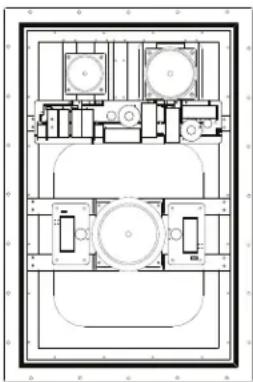
Architectural floor plan showing room layouts and structural elements (no text or labels)IS4 SST
The IS4 SST features single stereo technology, the ability to drive one speaker with two inputs. The IS4 SST is impedance matched to ensure proper amplifier protection. The perfect choice for small areas, such as hallways and corridors where two speakers would be impractical or impossible to install.
SPECIFICATIONS
Tweeter 4 sq. in (27 sq. cm) planar diaphragm, driven by a 1" (25mm) dual voice coil
Midrange 17 sq. in (110 sq. cm) planar diaphragm, driven by a 1" (25mm) dual voice coil
Woofer 113 sq. in (732 sq. cm) planar diaphragm, driven by a 2" (50mm) dual voice coil
Frequency Response 40Hz - 20kHz ±3dB
Impedance 8 ohms nominal
Power Handling 100 watts RMS
Sensitivity 90dB (1W/1 meter)
Dispersion 170° hemispherical up to 10kHz
Finish Paper surface ready for texture and paint
Overload Protection Three independent self-resetting gel switches (low, mid and high)
Cutout Dims
Without Enclosure (WxHxD) 16-1/8" x 24-1/8" x 2" (409mm x 613mm x 51mm)
Cutout Dims -
With Enclosure (WxHxD) 16-1/8" x 24-1/8" x 3-13/16" (409mm x 613mm x 97mm)
Shipping Weight 13 lbs (5.85 kg) each
natural_image
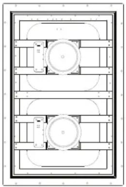
Architectural floor plan showing two circular room layouts with horizontal and curved structural elements (no text or labels)ISW
The ISW is a low frequency reinforcement to the IS line. Two voice coils drive the diaphragm for unsurpassed invisible low end response.
SPECIFICATIONS
Woofer 170 sq. in (1098 sq. cm) planar diaphragm, driven by two 2" (50mm) voice coils
Frequency Response 35Hz - 150Hz ±3dB
Impedance 8 ohms nominal
Power Handling 100 watts RMS
Sensitivity 90dB (1W/1 meter)
Dispersion 170° hemispherical up to 10kHz
Finish Paper surface ready for texture and paint
Overload Protection Self-resetting gel switch
Cutout Dims
Without Enclosure (WxHxD) 16-1/8" x 24-1/8" x 2" (409mm x 613mm x 51mm)
Cutout Dims -
With Enclosure (WxHxD) 16-1/8" x 24-1/8" x 3-13/16" (409mm x 613mm x 97mm)
Shipping Weight 13 lbs (5.85 kg) each
natural_image
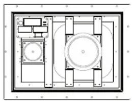
Architectural floor plan showing room layout with central circular space and surrounding furniture (no text or labels)IS2
The IS2 is designed for tight installations or very small spaces yet delivers sound that is only bested by the IS4.
SPECIFICATIONS
Tweeter 4 sq. in (27 sq. cm) planar diaphragm, driven by a 1" (25mm) voice coil
Woofer 50 sq. in (320 sq. cm) planar diaphragm, driven by a 1" (25mm) voice coil
Frequency Response 50Hz - 20kHz ±3dB
Impedance 8 ohms nominal
Power Handling 80 watts RMS
Sensitivity 88dB (1W/1 meter)
Dispersion 170° hemispherical up to 10kHz
Finish Paper surface ready for texture and paint
Overload Protection Two independent self-resetting gel switches (low and high)
Cutout Dims
Without Enclosure (WxHxD) 16-1/8" x 12-1/8" x 2" (409.5mm x 307mm x 51mm)
Cutout Dims -
With Enclosure (WxHxD) 16-1/8" x 12-1/8" x 3-13/16" (409.5mm x 307mm x 97mm)
Shipping Weight 12 lbs (5.5 kg) pair

INVISIBLE SERIES SPEAKER INSTALLATION DETAIL VIEW
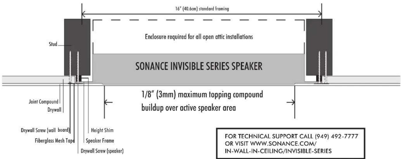
Note: IMPORTANT CONSIDERATION FOR LOCATING THE IS2, IS4, IS4SST AND ISW ON WALLS
For wall installations, locate the bottom of the Invisible Series Speaker at least 7 ft. (2.1m) up from the floor. Placing the speaker lower on the wall will put it at risk for having picture nails or other hanging devices driven through the diaphragm and damaging the speaker. Since the final surface finish enables the speaker to completely disappear, it is critical to locate the speaker high enough on the wall to protect it for the future. Resulting damage of this type is not covered by the warranty.
WIRE GAUGE GUIDE
Extra resistance in the speaker wire can make speakers sound less dynamic and reduce definition of the bass frequencies. In extreme cases, it can even attenuate high frequencies. Also, amplifier power is wasted in wire with extra resistance, reducing your system's maximum output level. To prevent degrading sound quality, the total wire resistance should be less than 10% of the speaker's impedance. This means that for an 8-ohm speaker, the total resistance of the wire should be less than 0.8 ohms. Refer to the following table when selecting the proper wire gauge for your system:
| WIRE RESISTANCE IN OHMS vs. LENGTH OF CABLE RUN | ||||||
| DISTANCE IN FEET | 50' | 100' | 150' | 200' | 250' | 300' |
| 20 Gauge | 1.04 | 2.07 | 3.11 | 4.14 | 5.18 | 6.22 |
| 18 Gauge | .65 | 1.30 | 1.96 | 2.61 | 3.26 | 3.91 |
| 16 Gauge | .41 | .82 | 1.22 | 1.63 | 2.04 | 2.45 |
| 14 Gauge | .26 | .52 | .77 | 1.03 | 1.29 | 1.55 |
| 12 Gauge | .16 | .32 | .49 | .65 | .81 | .97 |
| 10 Gauge | .10 | .20 | .31 | .41 | .51 | .61 |
NEW CONSTRUCTION
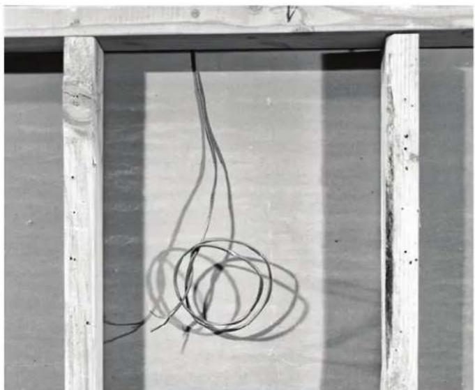
I. Wire stud bay prior to mounting drywall. See page 4 for wire gauge chart.
natural_image
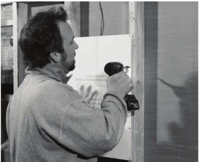
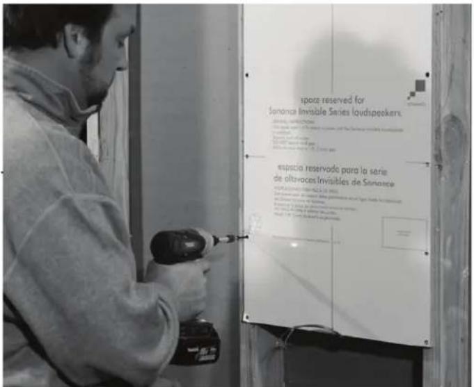
Close-up of a rope tied with a coiled wire against a wooden frame (no text or symbols visible)- With the aid of a level, screw the space saver to the studs. Ensure the speaker cable will have easy access once the space saver is removed.
natural_image
Man in workwear using a power tool on a door panel, no visible text or symbolsSpace Saver Part Numbers:
IS4 & ISW = 92723
IS2 = 92722
- Place space saver in desired final location of speaker.
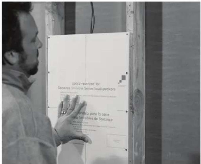
- Secure edges of the space saver.
NEW CONSTRUCTION
- After all drywall is hung, begin speaker installation by removing space saver.
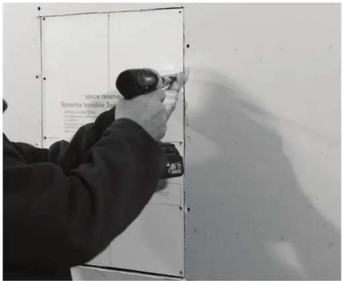
- Be careful not to damage the exposed drywall during space saver removal.

NEW CONSTRUCTION
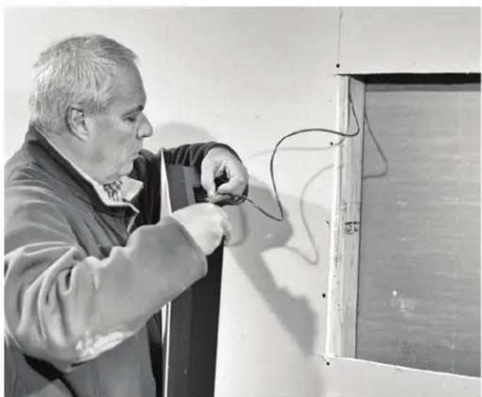
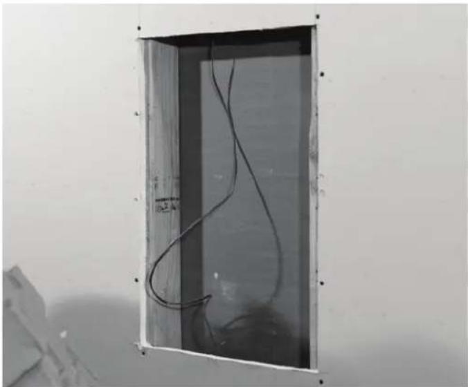
- Pull 2-conductor speaker wire down into the exposed opening.
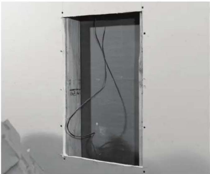
natural_image
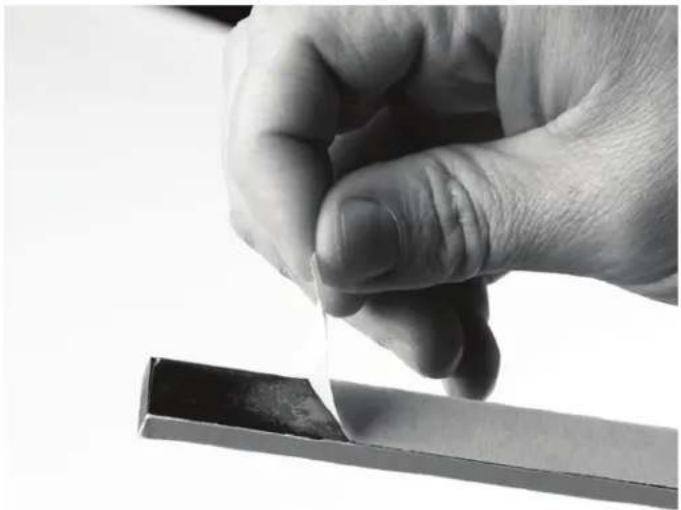
Exterior view of a modern office building (no signage)- Peel off corresponding adhesive backing.
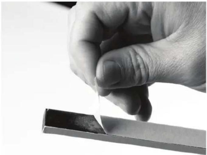
natural_image
Close-up of a hand holding a thin, metallic object with a dark rectangular base (no visible text or symbols)-
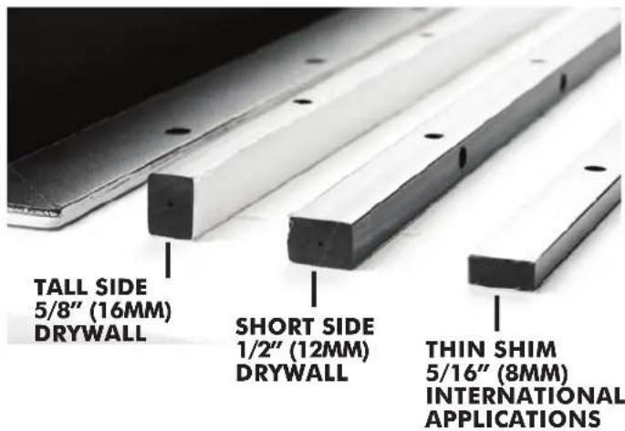
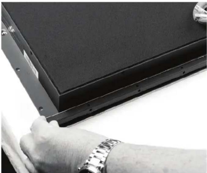
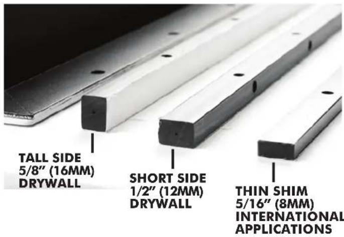
Select the appropriate shim for the application.* Use cardboard shims for fine tuning.
-
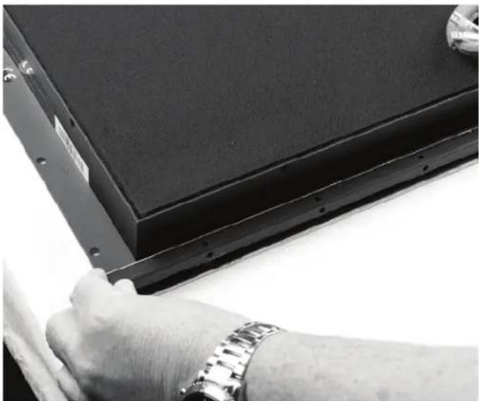
Press shim firmly into position, aligning screw holes.
natural_image
Close-up of a hand adjusting a black electronic component with a wristwatch (no visible text or symbols)*All installations in 1/2" (13mm) and 5/8" (16mm) drywall with wood stud construction require a shim.
NEW CONSTRUCTION
-
Connect speaker wire to the appropriate terminal on the speaker. (Speaker shown with optional enclosure.)
-
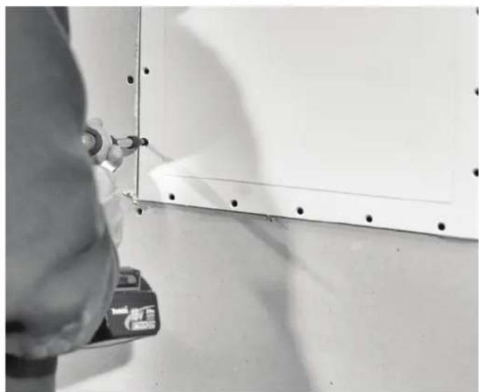
Secure speaker with at least 4 drywall screws on each side. Top and bottom are optional. Do not over tighten.
natural_image
Man working on electrical wiring inside a room with exposed wiring (no visible text or symbols)Enclosure Part Numbers:
$$ \text { IS4 } \& \text { ISW } = 9 2 9 7 0 $$
$$ \mathrm{IS2} = 9 2 9 6 9 $$
- Insert speaker into opening.
natural_image
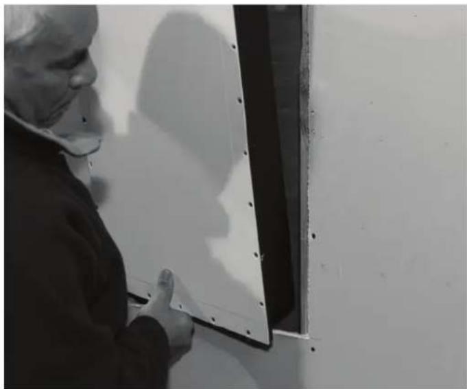
Close-up of a hand using a tool to mark a white panel edge, no visible text or symbolsTEST THE SPEAKER FOR 60 SECONDS WITH AN AUDIO SOURCE BEFORE COVERING WITH DRYWALL COMPOUND!
This is the last point any wiring corrections can be made. After test is complete finish securing with remaining drywall screws.
natural_image
Person wearing safety goggles and mask inspecting a wall panel with holes (no visible text or symbols)- Go to Finishing Instructions starting on page 12.
I. Determine the location for the speaker.
2. Using a stud finder, locate the first studs/joists to the right and left of the speaker position.
3. Mark the centers of the studs/joists. (See Figure 4, below.)
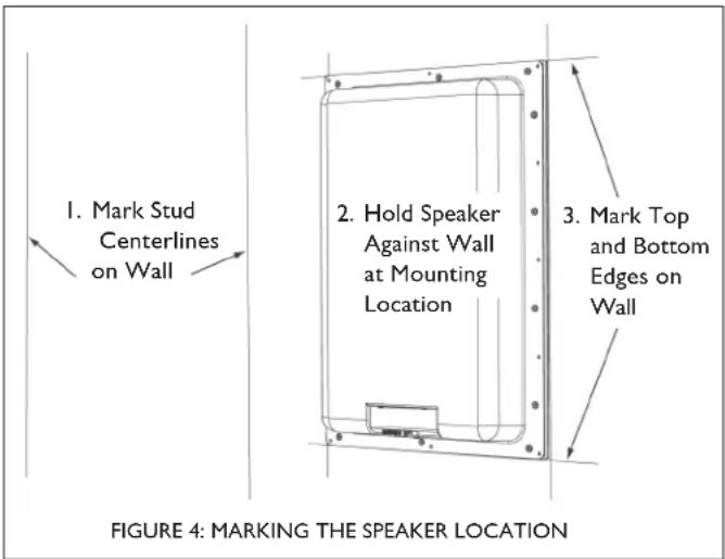
- Using the speaker as a template, determine the desired speaker location on the wall. Mark the speaker's top and bottom edges on the drywall. (See Figure 4, above.)
- Before proceeding, perform an obstruction survey to be certain that there are no studs, conduit, pipes, heating ducts, pocket doors, or air returns in the wall cavity that will interfere with the speaker.
- Using a drywall saw, cut the drywall along the top and bottom horizontal marks UP TO THE INSIDE EDGES OF THE LEFT AND RIGHT STUDS/JOISTS. (See Figure 5 below.)
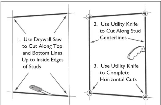
FIGURE 5: CUTTING THE MOUNTING HOLE
- Using a utility knife, cut the drywall along the vertical marks at the centers of the studs/ joists. Use the utility knife to complete the horizontal cuts at each stud/joist. (See Figure 5, below.) Remove the drywall from the opening.
- This should expose only 34'' (19mm) of each stud/joist or half of the stud/joist surface. (See Figure 6.)
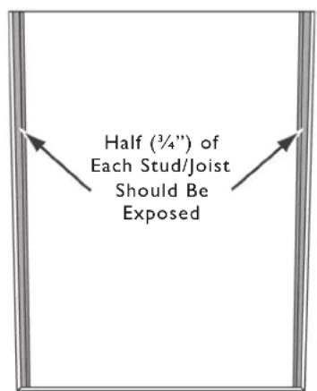
FIGURE 6: EXPOSED STUDS AFTER DRYWALL IS REMOVED
- Test-fit the speaker into the opening, verifying that all of the speaker's edges are even with the drywall edges. If necessary, trim the edges of the drywall to properly accommodate the speaker.
EXISTING CONSTRUCTION
- Pull 2-conductor speaker wire down into the exposed opening.
natural_image
Exterior view of a modern office building (no signage)II. Peel off corresponding adhesive backing.
natural_image
Close-up of a hand holding a thin, metallic object with a dark rectangular base (no visible text or symbols)- Select the appropriate shim for the application.* Use cardboard shims for fine tuning.
- Press shim firmly into position, aligning screw holes.
natural_image
Close-up of a hand adjusting a black electronic component with a wristwatch (no visible text or symbols)*All installations in 1/2" (13mm) and 5/8" (16mm) drywall with wood stud construction require a shim.
EXISTING CONSTRUCTION
-
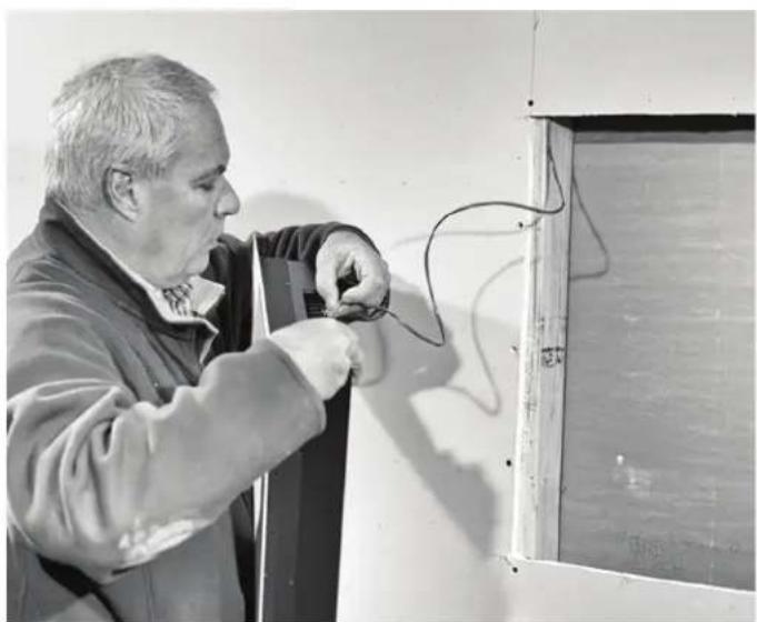
Connect speaker wire to the appropriate terminal on the speaker. (Speaker shown with optional enclosure.)
-
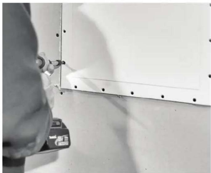
Secure speaker with at least 4 drywall screws on each side. Top and bottom is optional. Do not over tighten.
natural_image
Black-and-white photo of a man working on electrical wiring near a door (no visible text or symbols)Enclosure Part Numbers:
$$ \mathrm{IS4} \& \mathrm{ISW} = 9 2 9 7 0 $$
$$ \mathrm{IS2} = 9 2 9 6 9 $$
- Insert speaker into opening.
natural_image
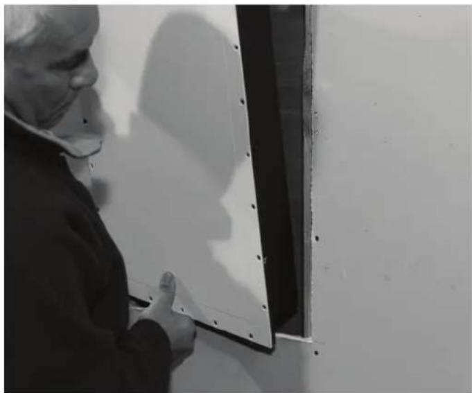
Close-up of a hand using a tool to clean or mark a white panel on a wall, with no visible text or symbols.TEST THE SPEAKER FOR 60 SECONDS WITH AN AUDIO SOURCE BEFORE COVERING WITH DRYWALL COMPOUND!
This is the last point any wiring corrections can be made. After test is complete finish securing with remaining drywall screws.
natural_image
Black-and-white photo of a person wearing a mask and gloves, leaning against a wall with a black panel (no visible text or symbols)FINISHING INSTRUCTIONS
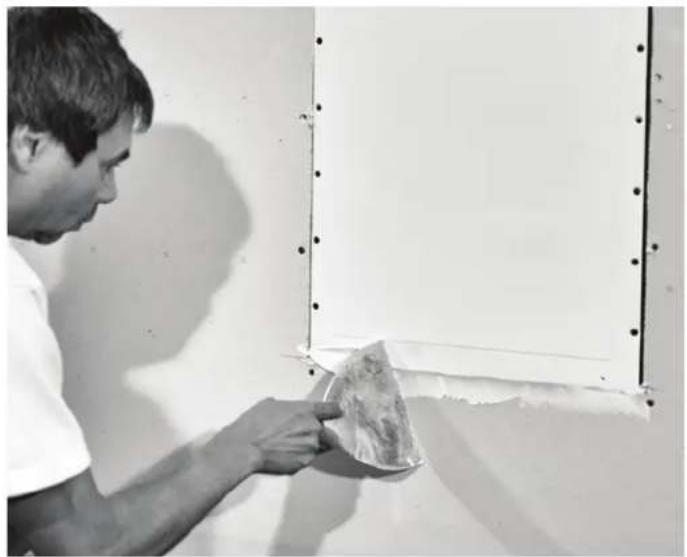
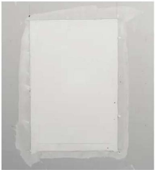
I. Fill the gap between speaker and drywall with 5 minute setting type joint compound (hot mud).
natural_image
Man applying plaster to a wall panel, no visible text or symbols- Allow hot mud to set slightly before applying mesh tape.
natural_image
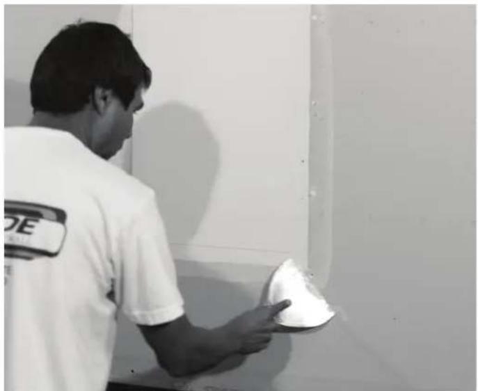
Plain white square frame with a thin black border, no text or symbols visible- Feather all edges.
natural_image
Person in a white T-shirt applying material to a wall-mounted device (no visible text or symbols)FINISHING INSTRUCTIONS
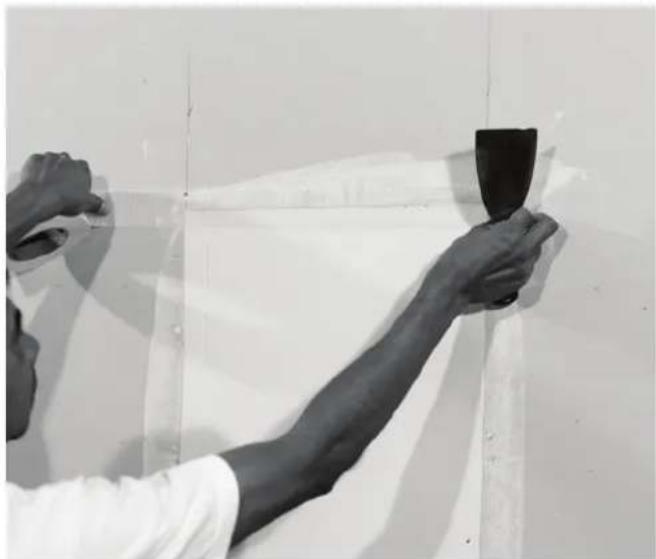
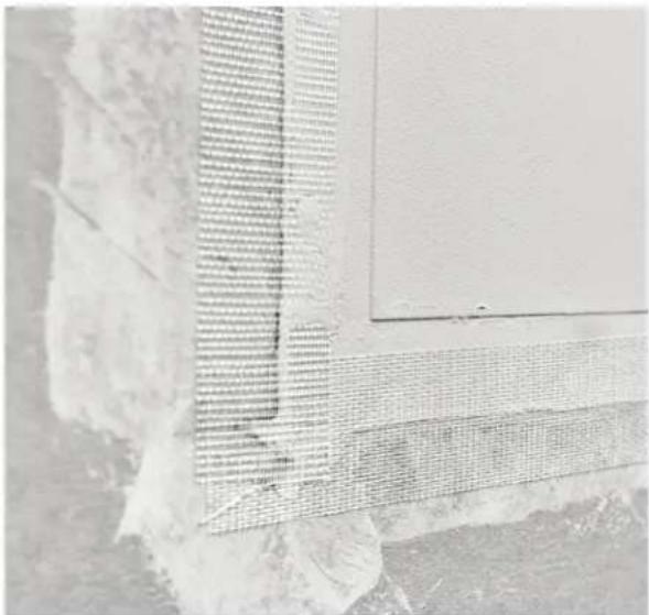
- Place mesh tape over the drywall seams.
natural_image
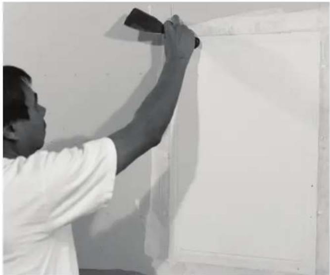
Person holding a black object against a plain wall, no visible text or symbols- Overlap tape slightly.
natural_image
Person painting on a white wall, no visible text or symbols- Do not tape over the raised portion of the speaker (diaphragm).
natural_image
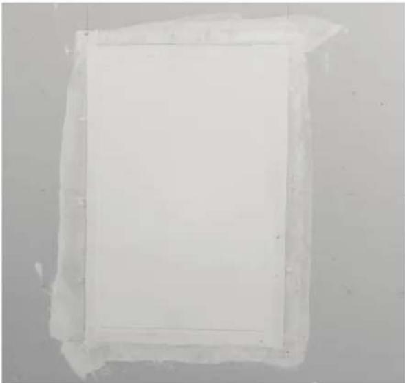
Exterior view of a modern building with grid pattern and adjacent structure (no visible text or symbols)- Allow hot mud to fully cure or harden.
natural_image
Transparent rectangular object with a grid pattern, possibly a panel or container, against a plain background (no text or symbols visible)FINISHING INSTRUCTIONS
-
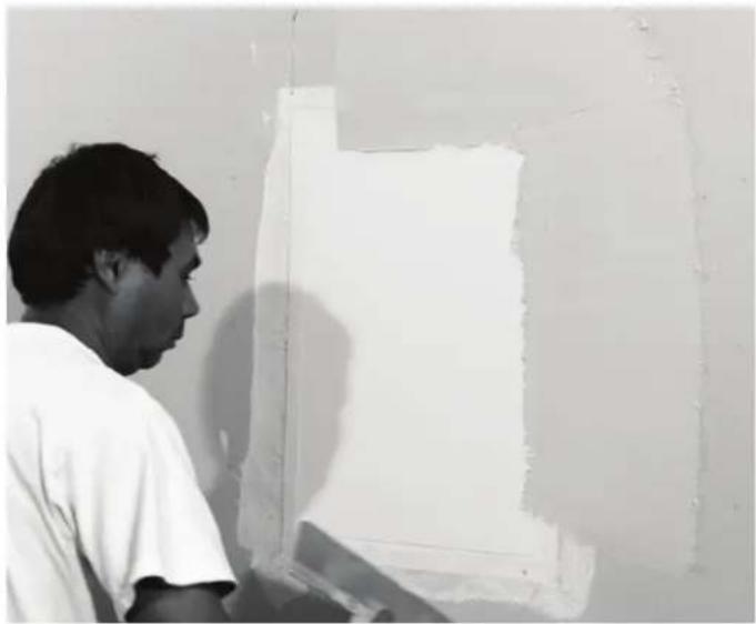
Once hot mud has fully cured or hardened, begin to Build layers of topping compound over speaker.
-
Feather in all surfaces.
natural_image
Black-and-white photo of a person viewing a white panel on a wall, no visible text or symbols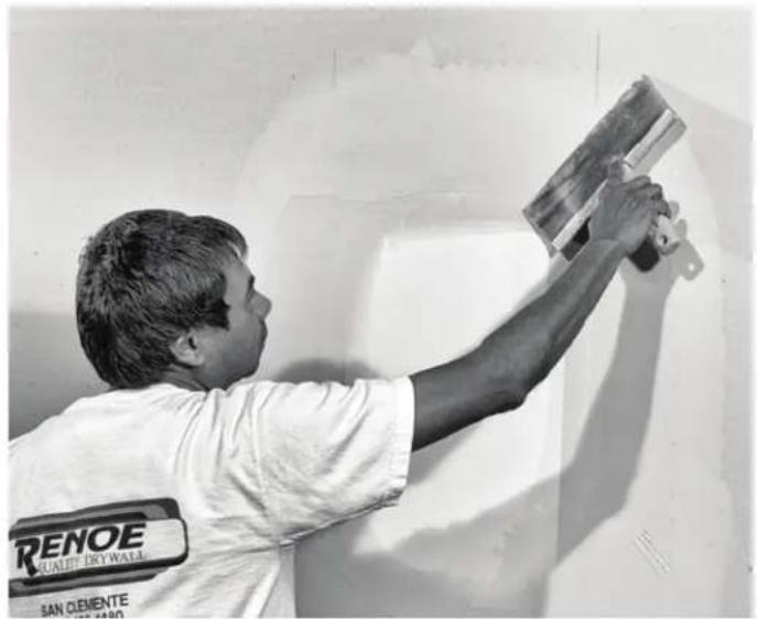
natural_image
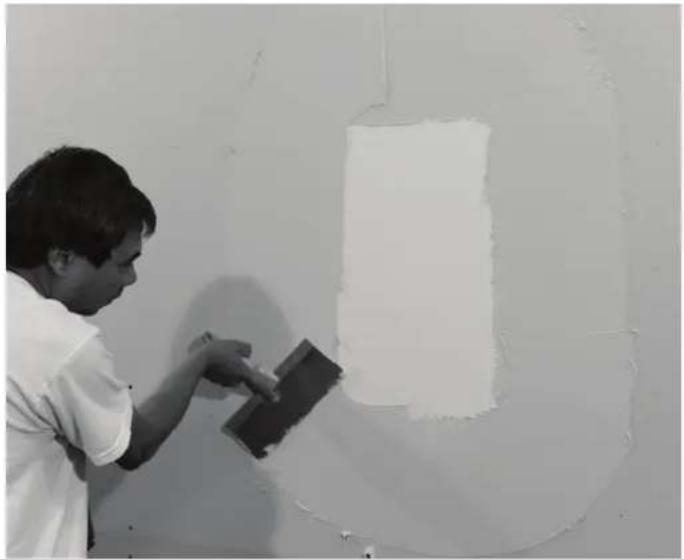
Person applying plaster to a wall, wearing a 'RENOE QUALITY DRY WALL' shirt (no visible text or symbols on the subject)- Build layers of compound as needed to obtain a flat surface.
II. Allow first coat to fully cure or harden.
natural_image
Person applying material to a wall with a large white block (no text or symbols visible)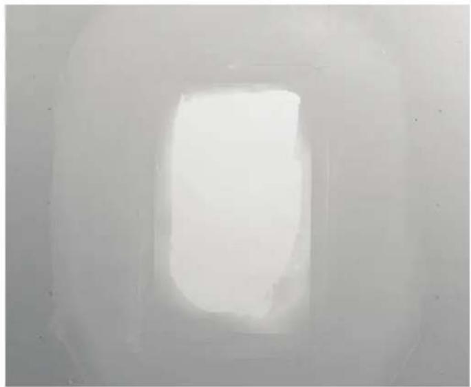
natural_image
Interior view of a dimly lit room with a bright central area, possibly a tunnel or space entrance (no visible text or symbols)FINISHING INSTRUCTIONS
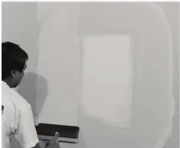
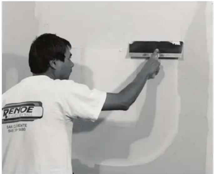
- Start a second coat covering the entire surface of the speaker and all adjoining surfaces.
natural_image
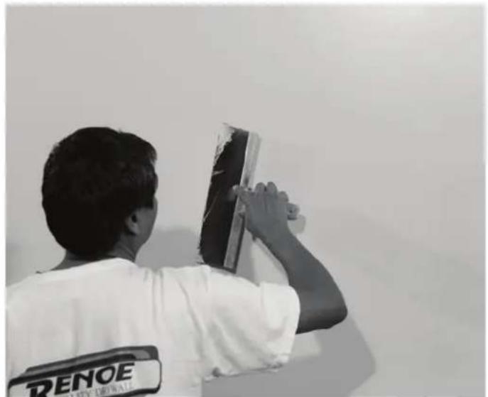
Person standing in front of a large white wall with a faint rectangular cutout (no visible text or symbols)- Detail the compound to minimize tool marks.
natural_image
Person wearing a white shirt with 'RENOE' patch, handling a dark object near a wall (no visible text or symbols)-
Compound buildup on the active surface of the speaker should not exceed 1/8" (3mm).
-
Build more coats as necessary to achieve desired finish.
natural_image
Man installing or adjusting a wall-mounted air conditioner unit (no visible text or symbols)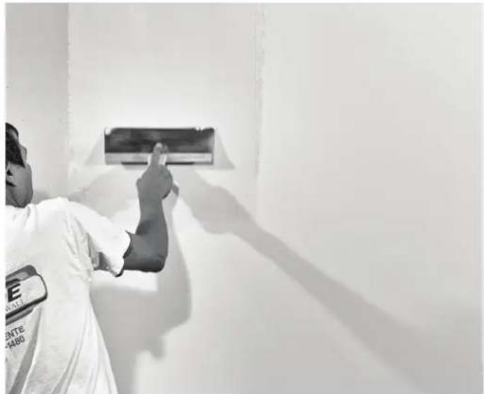
natural_image
Person installing or adjusting a wall-mounted device on a white wall (no visible text or symbols)FINISHING INSTRUCTIONS
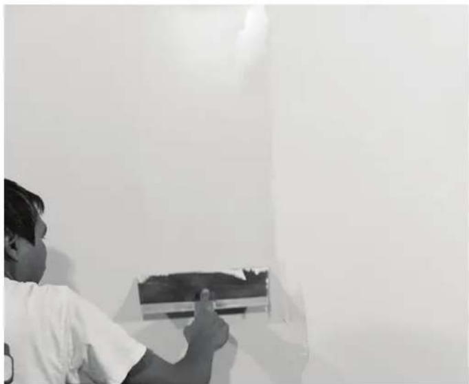
- Each successive coat should be thinner than the last. The final coat should be a very light application (skim coat).
natural_image
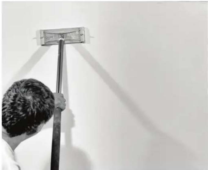
Person installing or adjusting a wall-mounted air conditioner unit (no visible text or symbols)- After final coat is applied and has dried, use a manual pole sander or block sander on entire wall (do not use a power sander). Wall surface should show no signs of a speaker. If any defect is found, skim coat entire area, and sand down again.
natural_image
Person cleaning a wall with a broom and light bulb (no text or symbols visible)IMPORTANT
TOTAL MATERIAL OVER ACTIVE SURFACE OF THE SPEAKER CAN NOT EXCEED 1/8 ^TH OF AN INCH (3mm).
BEST PRACTICE
A 60 MICRON SANDING FILM IS RECOMMENDED FOR FINAL SANDING.

SONANCE®
NOTES:
LIMITED FIFTEEN (15) YEAR WARRANTY
Sonance warrants to the first end-user purchaser that this Sonance-brand product ("Product"), when purchased from an authorized Sonance Dealer/Distributor and installed by a Sonance installer, will be free from defective workmanship and materials in the initial installation for the period stated below. Subject to the additional limitations stated below, Sonance will (a) at its option and expense during the warranty period, either repair the defect or replace the Product with a new or remanufactured Product or a reasonable equivalent, and (b) arrange at its reasonable expense to re-install the Product and prepare the surface of the speaker and/or mounting platform for finishing and nothing more.
EXCLUSIONS
TO THE EXTENT PERMITTED BY LAW, THE WARRANTY SET FORTH ABOVE IS IN LIEU OF, AND EXCLUSIVE OF, ALL OTHER WARRANTIES, EXPRESS OR IMPLIED, AND IS THE SOLE AND EXCLUSIVE WARRANTY PROVIDED BY SONANCE. ALL OTHER EXPRESS AND IMPLIED WARRANTIES, INCLUDING THE IMPLIED WARRANTY OF MERCHANTABILITY, IMPLIED WARRANTY OF FITNESS FOR USE, AND IMPLIED WARRANTY OF FITNESS FOR A PARTICULAR PURPOSE ARE SPECIFICALLY EXCLUDED. No one is authorized to make or modify any warranties on behalf of Sonance.
The warranty stated above is the sole and exclusive remedy and Sonance's performance shall constitute full and final satisfaction of all obligations, liabilities and claims with respect to the Product. IN ANY EVENT, SONANCE SHALL NOT BE LIABLE FOR CONSEQUENTIAL, INCIDENTAL, ECONOMIC, PROPERTY, BODILY INJURY, OR PERSONAL INJURY DAMAGES ARISING FROM THE PRODUCT, ANY BREACH OF THIS WARRANTY OR OTHERWISE.
This warranty statement gives you specific legal rights, and you may have other rights which vary from state to state. Some states do not allow the exclusion of implied warranties or limitations of remedies, so the above exclusions and limitations may not apply. If your state does not allow disclaimer of implied warranties, the duration of such implied warranties is limited to the period of Sonance's express warranty.
Your Product Model and Description: Sonance Invisible Series Speaker IS4, IS4 SST, ISW, IS2
Warranty Period for this Product: Fifteen (15) years from the date on the original sales receipt, invoice or other satisfactory proof of purchase.
Additional Limitations and Exclusions From Warranty Coverage: The warranty described above is non-transferrable, applies only to the initial installation of the Product, does not include re-finishing of the speaker and/or mounting platform or surrounding surface, does not include damage to allied or associated equipment which may result for any reason from use with this Product, and does not include Product failure caused by accident, disaster, negligence, improper installation, misuse (e.g. overdriving the amplifier or speaker, excessive heat or cold or humidity, outdoor installation), or from service or repair which has not been authorized by Sonance.
Obtaining Authorized Service: To qualify for the warranty, you (1) must contact your authorized Sonance Dealer/Installer or call Sonance Customer Service at (949) 492-7777 within the warranty period, (2) must obtain a return merchandise number (RMA), and (3) deliver the Product to Sonance shipping prepaid during the warranty period, together with the original sales receipt, invoice or other satisfactory proof of purchase.

SONANCE®
©2017. All rights reserved. SONANCE and SONANCE INVISIBLE SERIES are registered trademarks of Dana Innovations.
Due to continuous product improvement, all features and specifications are subject to change without notice.
For the latest SONANCE product specification information visit our website: www.sonance.com
991 Calle Amanecer | San Clemente, CA 92673 USA
T. (949) 492-7777 | F. (949) 361-5151
33-5758
Rev05.11.17

Brand : SONANCE
Model : IS2
Category : Pregnant