AA400PHD - Blender Atlas Sound - Free user manual and instructions
Find the device manual for free AA400PHD Atlas Sound in PDF.


| Product Type | Mixer Amplifier |
| Power Output | 400W RMS into 4Ω, 25V, or 70.7V lines |
| Inputs | 4 balanced Mic/Line/Telephone inputs (Phoenix), 3 unbalanced summed line inputs (2 RCA, 1 stereo 3.5mm) |
| Outputs | Main: 4Ω, 25V, or 70.7V (Phoenix) • Zone 2: unbalanced 600Ω/10kΩ (max 1.0V) • Pre Out: RCA, unbalanced 150Ω |
| Frequency Response | 50Hz–15kHz ±3dB |
| THD+N | ≤0.5% at 1kHz, rated output |
| Signal-to-Noise Ratio | >55dB (Mic, Line, Telephone) • Inputs 5&6: >75dB |
| Phantom Power | 24VDC selectable for Inputs 1–4 |
| Dimensions (W×H×D) | 420mm × 93mm × 422mm (16.54" × 3.66" × 14.6") |
| Weight | 15.8 kg (41.6 lbs) |
| Power Requirements | 120V, 60Hz; idle 0.32A / 38W, average 5.4A / 648W, max burst 8.4A / 1008W |
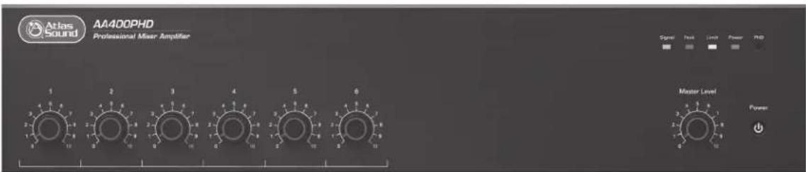
| Front Panel Controls | Power switch, Master level, Input 1–6 level controls, PHD test switch (momentary) |
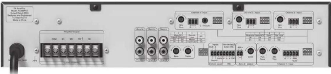
| Rear Panel Controls | Bass/Treble tone controls, Mic trim for Inputs 1–4, VOX mute sensitivity, DIP switches for each input (phantom, mute receive, Zone 2, Mic/Line) |
| PHD Diagnostic System | Push Here Diagnostic for testing 70V distributed speaker systems; detects wiring faults, incorrect load, or speaker tap errors |
| Remote Control | Remote Level Control port (10kΩ potentiometer) and Remote Input Select (RIS) port for selecting inputs 4, 5, 6 (ground-activated) |
| Zone 2 Output | Music-on-hold output; level control, assignable from Inputs 1–4 via DIP switches |
| Pre Out / Amp In | Pre Out (RCA) for effects loop or feeding a second amp; Amp In converts unit to slave amplifier |
| Mute Functions | Contact closure mute (remote) or VOX mute triggered by Input 1; mute receive assignable per input via DIP switches |
| Speaker Outputs | Class 2 rated; terminals for COM, 4Ω, 25V, 70.7V; accepts up to 12 AWG wire |
| Safety & Compliance | ETL listed to UL 60065; grounded power cord; automatic current limiting; thermal protection |
| Warranty | 3 years for Atlas Sound products (electronics & controls: 1 year) |
| Cleaning & Maintenance | Clean with dry cloth only; unplug during storms or long inactivity; internal cleaning by qualified service |
| Spare Parts & Repairability | Contact Atlas Sound for service; optional security knob covers (AAVCC-5) available |
Frequently Asked Questions - AA400PHD Atlas Sound
User questions about AA400PHD Atlas Sound
0 question about this device. Answer the ones you know or ask your own.
Ask a new question about this device
Download the instructions for your Blender in PDF format for free! Find your manual AA400PHD - Atlas Sound and take your electronic device back in hand. On this page are published all the documents necessary for the use of your device. AA400PHD by Atlas Sound.
USER MANUAL AA400PHD Atlas Sound
natural_image
Abstract black-and-white logo design featuring a stylized letter 'A' with a circular arc and a dot, no text or symbols present.Atlas Sound
AA400PHD 400W Mixer Amplifier
Important Safety Instructions....3
Introduction 5
Key Features.... 5
Applications 5
Front Panel Description 6
Rear Panel Description....7
PHD Diagnostic System Test....12
Common Amplifier Failure Conditions....12
Trouble Shooting the Fault LED....13
How to Calculate Load Impedance 13
Remote Level Control....15
Remote Input Select (RIS) 16
Wiring the AA400PHD 17
Level Control Security Cover Option 17
Block Diagram 18
Specifications 19
Warranty 24
Important Safety Instructions

ATTENTION

RISQUE DE CHOC ÉLECTRIQUE
- NE PAS OUVRIR.

CAUTION
WARNING
TO REDUCE THE RISK OF FIRE OR ELECTRIC SHOCK DO NOT EXPOSE THIS APPLIANCE TO RAIN OR MOISTURE.

The lightning flash with arrowhead symbol within an equilateral triangle, is intended to alert the user to the presence of uninsulated "dangerous voltage" within the product's enclosure that may be of sufficient magnitude to constitute a risk of electric shock to persons.

The exclamation point within an equilateral triangle is intended to alert the user to the presence of important operating and maintenance (servicing) instructions in the literature accompanying the product.
- Read these instructions.
- Keep these instructions.
- Heed all warnings.
- Follow all instructions.
- Do not use this device near water.
- Clean only with dry cloth.
- Do not block any ventilation openings. Install in accordance with the manufacturer's instructions.
- Do not install near any heat sources such as radiators, heat registers, stoves, or other device (including amplifiers) that produce heat.
- Do not defeat the safety purpose of the polarized or grounding-type plug. A polarized plug has two blades with one wider than the other. A grounding type plug has two blades and a third grounding prong. The wide blade or the third prong are provided for your safety. If the provided plug does not fit into your outlet, consult an electrician for replacement of the obsolete outlet.
- Protect the power cord from being walked on or pinched particularly at plugs, convenience receptacles, and the point where they exit from the device.
- Only use attachments/accessories specified by the manufacturer.
- Use only with the cart, stand, tripod, bracket, or table specified by the manufacturer, or sold with the device. When a cart is used, use caution when moving the cart/device combination to avoid injury from tip-over.
- Unplug this device during lightning storms or when unused for long periods of time.
- Refer all servicing to qualified service personnel. Servicing is required when the device has been damaged in any way, such as power-supply cord or plug is damaged, liquid has been spilled, or objects have fallen into the device, the device has been exposed to rain or moisture, does not operate normally, or has been dropped.
- WARNING: To reduce the risk of fire or electric shock, do not expose this apparatus to rain or moisture.
Avertissement: pour réduire le risque d'incendie ou de choc électrique, ne pas exposer cet appareil sous la pluie et l'humidité. - The apparatus shall not be exposed to dripping or splashing and no objects filled with liquids, such as vases, shall be placed on apparatus.
L'appareil ne doit pas être exposé aux écoulements ou aux éclaboussures et aucun objet ne contenant de liquide, tel qu'un vase, ne doit être placé sur l'objet. - The mains plug is used as a disconnect device. The mains plug of the apparatus should not be obstructed OR should be easily accessed during intended use. To completely disconnect the power input, the mains plug of apparatus shall be disconnected from the mains.
La prise du secteur est utilisé pour déconnecter le système. La prise du secteur ne doit pas être obstruée ou doit être facilement accessible pendant son utilisation. Pour être complètement déconnecté de l'alimentation d'entrée, la prise doit être débranchée du secteur. - This product shall be connected to a mains socket outlet with a protective earthing connection.
Cet appareil doit être connecté à une prise électrique dotée d'une mise à la terre.

Atlas Sound
1601 Jack McKay Blvd. • Ennis, Texas 75119 U.S.A.
Telephone: 800.876.3333 • Fax: 800.765.3435
- 3 - AtlasSound.com

THAWARNING Use
- To prevent electric shock, do not remove the product cover as there are high voltage components inside. Refer all servicing to Atlas Sound.
- Should any of the following irregularities occur during use, immediately switch off the power, disconnect the power cord from the AC outlet and contact Atlas Sound. Do not to attempt to continue operation with the product as this may cause fire or electric shock:
- Smoke or strange smell coming from the unit.
- If the product falls or the case is damaged.
- If water or any metallic objects falls into the product.
- If the power supply cord is damaged in any way.
- If the unit is malfunctioning.
- Do not insert or drop metallic objects or flammable materials into the ventilation holes of the product's cover, as this may result in electric shock or fire.
- Do not place any containers with liquid or metallic objects on the top of the product. If any liquid spills into the unit, fire or electric shock may result.
- Never operate this product or touch the power supply cord during an electrical storm, electric shock may result.
- Never exceed the power rating on the product when connecting equipment. Fire and/or property damage may result.
- Operate the product only with the voltage specified on the unit. Fire and/or electric shock may result if a higher voltage is used.
- Do not modify, kink, or cut the power cord. Do not place the power cord in close proximity to heaters and do not place heavy objects on the power cord, including the product itself, doing so may result in fire or electrical shock.
- Ensure that the safety ground terminal is connected to a proper ground. Never connect the ground to a gas pipe as a catastrophic disaster may result.
- Be sure the installation of the product is stable, avoid slanted surfaces as the product may fall and cause injury or property damage.

CAUTION When Installing The Product
- Plugging in or unplugging the power cord with wet hands may result in electric shock.
- Never move the unit with the power cord plugged into the wall, as damage to the power cord may result.
- When unplugging the cord from the wall, grasp the plug, NOT the cord.
- Never install this product in humid or dusty locations, nor in direct sunlight, near sources of heat, or in areas where sooty smoke or steam are present. Fire and electric shock may result.
- Keep all sides of the unit at least 3 ^1/2 away from objects that may obstruct air flow to prevent the unit's internal temperature rise.

CAUTION When The Product Is In Use
- Never place heavy objects on the product, causing it to fall and/or break, resulting in personal injury and property damage. In addition, the product itself may fall and cause injury and property damage.
- Contact Atlas Sound for instructions on cleaning the inside of the unit. Large accumulations of dust inside the unit may result in heat buildup and fire.
- Ensure that the power supply plug is securely plugged into the wall outlet. Never allow dust to accumulate on the power plug or inside the wall outlet.
- When cleaning the unit or the unit is not to be operated for an extended period, unplug the power cord from the wall.
Introduction
Congratulations and thank you for purchasing the Atlas Sound AA400PHD mixer amplifier. This new and innovative professional grade product has been designed from the ground up to include the important features that professional installation personnel require to meet or exceed their customer's expectations. Small, compact, and engineered for reliability, the Atlas Sound AA400PHD will provide years of service and flexibility in today's background music and paging applications.
Key Features
• 400W Into 25V/70.7V and 4Ω Loads
- Automated Diagnostic System Test (Push Here Diagnostic) for 70V Distributed Systems
• Four Balanced Mic/Line/Tel Inputs w/ Phantom Power
• Three Unbalanced, Summing Line Level Inputs
- Input Assignable Zone 2 Output
- Remote Level Control
- Remote Input Select (RIS)
- Preamp Out / Amp In for External Processors
• Variable Mute Sensitivity Control for Input 1
- Contact Closure Mute Terminals
- Rear Mounted DIP Switch Allows Mute Recieve for Inputs 2 Through 6
Applications
The Atlas Sound AA400PHD is the perfect choice for distributed business paging and background music (BGM) systems, small to medium speech privacy systems, and in applications where music on hold (MOH) plus paging is required.
Front Panel
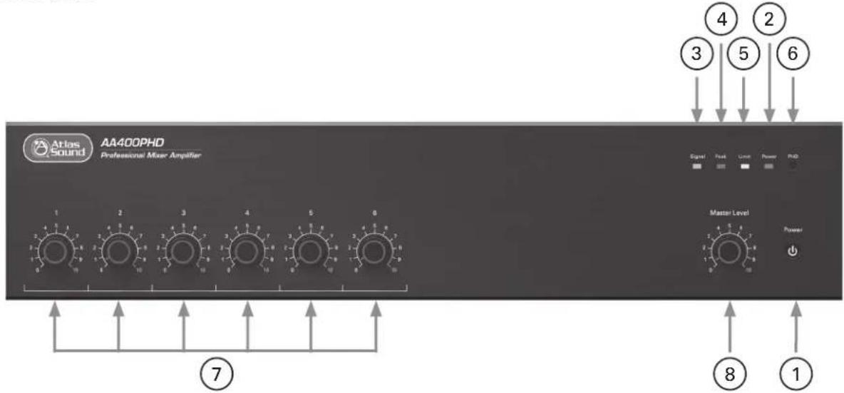
1. Power Switch
This push switch (On/Off) supplies power to the mixer amplifier.
2. Power Indicator
This LED illuminates Blue when the power switch is turned On.
3. Signal Indicator
When the signal LED illuminates Green, input signals are connected to the amplifier. The Signal LED is PRE the input level controls.
4. Peak Indicator
The AAPHD Series amplifier has an input signal peak limiter located between the preamp mixer stage and the power amplifier stage. This input signal peak limiter is designed to prevent the amplifier from being over driven by excess input signals that may cause damage to the amplifier. If the amplifier preamp stage senses excessive input signal, the peak limiter will engage reducing the signal and the Peak LED will illuminate Red. An occasional flash of the LED is OK. If ON steady state; turn the associated level control down until the Peak LED turns OFF. It may be necessary to reduce the signal level at the input of the amplifier.
5. Limit Indicator
This LED serves two functions:
A. PHD Test Circuit Load Fault Indicator - When testing the system using the PHD feature for proper wiring and amplifier loading, this LED will illuminate Yellow if a fault is sensed in the audio speaker system. See "Using the PHD Load Impedance Testing System." Note: For 70V distributed systems only.
B. Excessive Current Draw Limit Indicator - Will illuminate Yellow when the amplifier is consuming excessive current. At that point, a current limiting circuit is activated, reducing the output power to prevent damage to the amplifier. The most likely cause for the fault is an incorrect load impedance connected to the amplifier. The LED should not come on if a proper load is applied. If the Limit LED is illuminating, use the PHD Load Impedance test explained in the manual to help troubleshoot the cause of the problem. Note: An occasional LED flash is okay. When LED is ON audible distortion may be heard at the speakers.
6. PHD Switch
The AAPHD Series features a patent pending Amplifier Diagnostic System. The PHD (Push Here Diagnostic) is simple to use and very effective in testing the speaker wiring and load impedances on 70V speaker systems to assure the proper load is applied to the amplifier. Please read the section on "Using the PHD Feature" before activating the circuit. To activate the PHD circuit a small tool with a point will be required to access the momentary switch through the hole on the front panel. See "Using the PHD Mixer Amplifier Load Impedance Testing System."
Front Panel
7. Input 1-6 Level
The rotary control varies the amplitude of the signal fed to the amplifier input. Turn clockwise to increase and counter-clockwise to decrease the signal level.
8. Master Level
The Master Level control will raise or lower all the input channels together. A good starting point for setting gain structure is to set the Master Level control at the 12:00 position, and then adjust the individual channels one at a time.
Rear Panel
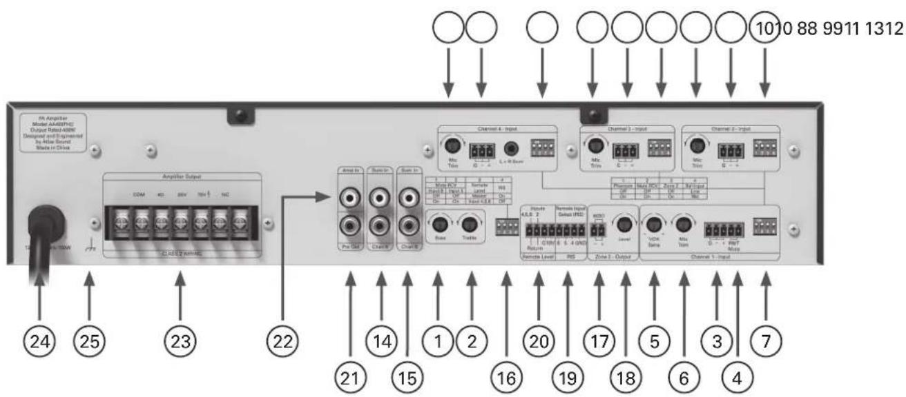
1. Bass Control
Normally set at the 12:00 position, rotating clockwise will increase (boost) bass frequencies to a maximum of +6dB at 100Hz. Rotating counter-clockwise from the 12:00 position will decrease (cut) bass frequencies to a maximum of -6dB at 100Hz.
2. Treble Control
Normally set at the 12:00 position, rotating clockwise will increase (boost) treble frequencies by +6dB at 10kHz. Rotating counter-clockwise from the 12:00 position will decrease (cut) treble frequencies by -6dB at 10kHz.
3. Input 1
Balanced Microphone or Line level signals connect to the (+), (-), and (G) terminals. To select between Mic or Line input levels, refer to the DIP switch chart on the rear of the amplifier for feature assignment. If connecting an unbalanced line level input, tie (short) the (G) and (-) terminals together for negative or ground connection and the positive or (+) signal to the (+) terminal on the amplifier input. If the input is used in Mic mode, Phantom power for condenser type microphones is available in the DIP switch settings on the rear panel. Input 1 level control located on the front panel adjusts the levels to the amplifier mix.
4. Remote Mute Connector
Shorting the Remote Mute terminals will mute the inputs that are assigned to receive the mute command. When an input is set to Mute Receive via the corresponding DIP switch, the input associated to the switch will be muted when terminals (G) and (M) are shorted together. This connection is usually done via remote switch on a microphone.
Rear Panel
5. VOX Mute Sensitivity Control
Input 1 signal can be used to trigger or activate a mute command. When an input is set to Mute Receive via the corresponding DIP switch, the input associated to the switch will be muted when a signal is applied to Input 1. The VOX Mute Sensitivity Control adjusts how sensitive the mute circuitry from Input 1 reacts. Setting the control fully counter-clockwise will lower the sensitivity, where a higher amplitude signal will be required at Input 1 to trigger the mute send circuits. Fully clockwise will raise the sensitivity of the mute circuits, where a lower amplitude signal will trigger a mute send. Calibration of this control in conjunction with the microphone to be used is very important to assure the proper amount of signal from the mic is enough to trigger the mute circuits. If it is not calibrated properly, the mute may not be triggered when a weak voice vs a strong voice uses the mic.
6. Mic Trim
This variable control allows fine tuning of the gain of input. There is 20dB of variable gain available. The trim only applies when the input is set to the "Mic" position on the DIP switch.
7. Multi Function DIP Switch Input 1
Understanding the functionality of the DIP switches is key to maximizing the versatility of the AAPHD Series. When a switch is in the up position, the function is "OFF or assigned to the feature stated"; when a switch is in the down position, the function is "ON or assigned to the feature stated".
| 1 | 2 | 3 | 4 |
| Phantom | Mute RCV | Zone 2 | Bal Input |
| Off | Off | Off | Line |
| On | On | On | Mic |
Switch A
- DP SW #1 - Input 1 Phantom Power 24VDC is active when Input 1 is set to Mic mode and the switch is in the ON position. Note: Only use this feature if you are using condenser microphones, otherwise leave in the "OFF" position.
- DP SW #2 - Mute Receive Input 1 - When "ON", Input 1 signal will be muted if a signal is present on Input 1 or if the Remote Mute Terminals are shorted together.
- DP SW #3 - Zone 2 Assign Input 1 - When "ON", Input 1 signal will be routed to the Zone 2 Output terminals. The signal routed is PRE the front panel level controls.
- DP SW #4 - When in the "MIC" position, Input 1 will accept microphone level signals; when in the "Line" position, Input 1 will accept line level or telephone signals.
8. Inputs 2 & 3
Balanced Microphone or Line level signals connect to the (+), (-), and (G) terminals. To select between Mic or Line input levels, refer to the DIP switch chart on the rear of the amplifier for feature assignment. If connecting an unbalanced line level input, tie (short) the (G) and (-) terminals together for negative or ground connection and the positive or (+) signal to the (+) terminal on the amplifier input. If the input is used in Mic mode, Phantom power for condenser type microphones is available in the DIP switch settings on the rear panel. Input 2 & 3 level controls located on the front panel adjust the levels to the amplifier mix.
9. Mic Trim Inputs 2 & 3
This variable control allows fine tuning of the gain of input. There is 20dB of variable gain available. The trim only applies when the input is set to the "Mic" position on the DIP switch.
Rear Panel
10. Multi Function DIP Switch Inputs 2 & 3
Understanding the functionality of the DIP switches is key to maximizing the versatility of the AAPHD Series. When a switch is in the up position, the function is "OFF or assigned to the feature stated"; when a switch is in the down position, the function is "ON or assigned to the feature stated".
| 1 | 2 | 3 | 4 |
| Phantom | Mute RCV | Zone 2 | Bal Input |
| Off | Off | Off | Line |
| On | On | On | Mic |
Switch A
- DP SW #1 - Input 1 Phantom Power 24VDC is active when Input 2 or 3 is set to Mic mode and the switch is in the ON position. Note: Only use this feature if you are using condenser microphones, otherwise leave in the "OFF" position.
- DP SW #2 - Mute Receive Inputs 2 & 3 - When "ON", Input 2 or 3 signal will be muted if a signal is present on Input 1 or if the Remote Mute Terminals are shorted together.
- DP SW #3 - Zone 2 Assign Inputs 2 & 3 - When "ON", Input 2 or 3 signal will be routed to the Zone 2 Output terminals. The signal routed is PRE the front panel level controls.
- DP SW #4 - When in the "MIC" position, Input 2 or 3 will accept microphone level signals; when in the "Line" position, Input 1 will accept line level or telephone signals.
11. Input 4
Input 4 can accept more than one type of audio signal. This input section has a 3 position Phoenix connector for Mic or Line input signals and a 3.5mm stereo jack that is summed. The level to the amplifier mix is controlled by Input 4 level located on the front panel.
Note: Only one type of input signal can be applied at one time.
A. Balanced Mic / Line - Balanced Microphone or Line level signals connect to the (+), (−), and (G) terminals. To select between Mic or Line input levels, refer to the DIP switch chart on the rear of the amplifier for feature assignment. If connecting an unbalanced line level input, tie (short) the (G) and (−) terminals together for negative or ground connection and the positive or (+) signal to the (+) terminal on the amplifier input. If the input is used in Mic mode, Phantom power for condenser type microphones is available in the DIP switch settings on the rear panel.
B. Input 4 Stereo Summed - Input 4 consists of stereo 3.5mm summing inputs, suitable for connection to the output of iPod ^® , CD/DVD players, etc.
12. Mic Trim
This variable control allows fine tuning of the gain of input. There is 20dB of variable gain available. The trim only applies when the input is set to the "Mic" position on the DIP switch.
Rear Panel
13. Multi Function DIP Switch Input 4
Understanding the functionality of the DIP switches is key to maximizing the versatility of the AAPHD Series. When a switch is in the up position, the function is "OFF or assigned to the feature stated"; when a switch is in the down position, the function is "ON or assigned to the feature stated".
Switch A
| 1 | 2 | 3 | 4 |
| Phantom | Mute RCV | Zone 2 | Bal Input |
| Off | Off | Off | Line |
| On | On | On | Mic |
- DP SW #1 - Input 4 Phantom Power 24VDC is active when Input 4 is set to Mic mode and the switch is in the ON position. Note: Only use this feature if you are using condenser microphones, otherwise leave in the "OFF" position.
- DP SW #2 - Mute Receive Input 4 - When "ON", Input 4 signal will be muted if a signal is present on Input 1 or if the Remote Mute Terminals are shorted together.
- DP SW #3 - Zone 2 Assign Input 4 - When "ON", Input 4 signal will be routed to the Zone 2 Output terminals. The signal routed is PRE the front panel level controls.
- DP SW #4 - When in the "MIC" position, Input 4 will accept microphone level signals; when in the "Line" position, Input 1 will accept line level or telephone signals.
14. Input 5
Input 5 consists of RCA stereo summing inputs, suitable for connection to the output of CD/DVD players, etc.
15. Input 6
Input 6 consists of RCA stereo summing inputs, suitable for connection to the output of CD/DVD players, etc.
16. Multi Function DIP Switch Inputs 5 & 6 and Remote
Understanding the functionality of the DIP switches is key to maximizing the versatility of the AAPHD Series. When a switch is in the up position, the function is "OFF or assigned to the feature stated"; when a switch is in the down position, the function is "ON or assigned to the feature stated".
Switch B
| 1 | 2 | 3 | 4 |
| Mute RCV | Remote Level | RIS | |
| Input 6 | Input 5 | ||
| Off | Off | Master | On |
| On | On | Input 4,5,6 | Off |
- DP SW #1 - Mute Receive Input 6 - When "ON", Input 6 signal will be muted if a signal is present on Input 1 or if the Remote Mute Terminals are shorted together.
- DP SW #2 - Mute Receive Input 5 - When "ON", Input 5 signal will be muted if a signal is present on Input 1 or if the Remote Mute Terminals are shorted together.
- DP SW #3 - Remote Level Port Assignment - Remote Level Port selection switch assigns the port to control Inputs 4, 5, and 6 or the Master Level. See Remote Level.
- DP SW #4 - Remote Input Select (RIS) - When "ON", RIS terminals are active. When active, no input will be present at the amplifier output unless the RIS input port pins are shorted to ground. See RIS ports.
17. Zone 2 Output Port
This terminal provides a 600Ω unbalanced output that is typically connected to a PBX music on hold port, also known as MOH. Inputs are assigned to the Zone 2 bus via switch associated with the input. Note: 10kΩ output impedance is available via the internal shunt selection.
Rear Panel
18. Zone 2 Output Level Control
This control will vary the level at the Zone 2 output terminals. Fully counter-clockwise (0) is Off, fully clockwise (10) is the maximum output level. The Zone 2 level control is PRE Input volume controls.
19. Remote Input Select (RIS) Port
Inputs 4, 5, & 6 can be remotely activated or selected. When any of the RIS input control port pins are shorted to ground, the signal from that input selected will be routed to the amplifier main mix bus. The RIS control port was designed to work with the Atlas Sound WPD-RISRL accessory item. See "Remote Input Selection and Level Control" for operation.
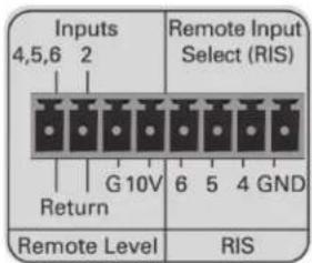
20. Remote Level Control Port
Remote location of a level control can be accomplished via the Remote Level control port. You can control Input 2, Inputs 4, 5, and 6, or the Master Level. Connections to a 10K pot requires three conductors and a minimum of 22 gauge wire. The return ports can be paralleled together if one pot is to control all inputs. The AAPHD series remote level design is based on 10VDC Return VCA type topology. Atlas Sound accessory level controls WPD-RISRL or WPD-VC10K can be used to achieve this.
The remote level control ports are PRE Input Level Controls and PRE the Master Level on the front panel. Set the system's maximum levels using the amplifier input level controls and then use the remote potentiometer as an attenuator from the maximum levels set.
21. Pre Out
The PRE OUT RCA port is POST the preamp mix bus but PRE the Master Level. This feature is used in two applications.
A. Effects loop - Used in conjunction with the AMP IN connector, an effects loop can be created by connecting the PRE OUT jack to a device such as an equalizer or DSP and then back out to the AMP IN connector.
B. Second Amplifier - If the amplifier output power is not enough you can use the mixer amp as a preamp to feed a second amplifier of choice. Note: The Master level will not be functional for the application.
22. Amp In
The AMP IN connector is useful for converting the AAPHD into a slave amp. When a line level signal is connected to this input, the internal connection between the preamp and internal power amp is broken. Audio signals applied to this connector are POST tone control and input level controls. The Master Level will function.
23. Amplifier Outputs
For loudspeaker connections, connect as follows or proceed to the setup section for typical wiring schemes.
• COM - Speaker common or negative connection
• 4Ω - Connect to direct coupled loudspeakers
• 25V - Connect to transformer coupled loudspeakers
• 70V - Connect to transformer coupled loudspeakers
24. Power Cord
Connect this grounded power cord to 120VAC circuits only. Serious damage may result otherwise.
25. Ground Terminal
Connect this terminal to electrical ground as required by local codes.

Atlas Sound
1601 Jack McKay Blvd. • Ennis, Texas 75119 U.S.A. Telephone: 800.876.3333 • Fax: 800.765.3435
Using the PHD Mixer Amplifier Diagnostic System
The AAPHD Series features a patent pending Amplifier Self Diagnostic System. The PHD (Push Here Diagnostic) is simple to use and is very effective running a 70V distributed system diagnostic test to assure the amplifier has the proper load applied. The proper load will assure a long lasting trouble free audio experience with your new AAPHD Series amplifier. Many amplifiers fail because an incorrect load is applied to the amplifier. This is especially true when using the amplifier in a 25V or 70V distributed audio speaker system. There are a few common failure points that can occur during system installation that are listed below.
Common Amplifier Failure Conditions, also see "How to Trouble Shoot Your Speaker System if the Limit LED is Illuminating".
- A short in the speaker wiring.
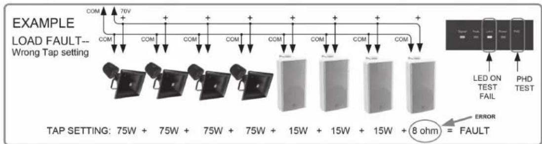
- Improper load selection or power tap setting on 70V speaker systems. It is very common when using many speakers to have one of the speakers tapped accidentally at 8Ω. This error will definitely be very hard on a 70V amp and in most cases cause the amp to fail within a few days. This kind of error is easy to make, time consuming to find and costly to fix.
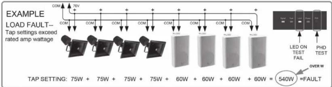
- Too many speakers attached or the wrong power taps are selected. If a 100 watt amp is used in a 70V system and it has ten speakers all tapped at 10W, but three of the speakers are accidentally tapped at 30W, that comes up to 160W of power required to drive the system properly. While it may work at low levels, as soon as the system needs to be louder the amp will be strained and could fail over time.
Most amplifier failures are caused by improper installation on the speaker side. There are two known ways to test the speaker system after everything is installed.
A. Measure the speaker system using a true audio frequency impedance meter. These are the best way to see if your speaker system is wired correctly for the amplifier.
B. Run the PHD Self Diagnostic test.
Running a Self-Diagnostic Test using the PHD Feature
Step 1 - Install the AAPHD Mixer amplifier, connect the input signals. Turn all levels to minimum. Do not attach the speaker system to the amp at this point.
Step 2 - Install the 70V distributed speaker system per the design, double check speaker tap settings. The total power for all the speakers should NOT exceed the maximum power rating of the amplifier installed.
Step 3 - Connect the speaker system to the amplifier. Pay special attention when connecting the speaker leads to the proper terminals on the amplifier. Note: All speaker power taps must be on a 70V setting.
Step 4 - Turn the amplifier On.
Important: Input levels are to be turn down or off. The Master Level is to be around 12 o'clock position or close to half way up. Note: If the Master Level is OFF or down the PHD test will not work.
Step 5 - Before starting the system Diagnostic test. Make sure no people are present or near the speakers during the diagnostic test without taking proper precautions. A 1 watt test tone will be present at each speaker. The audible SPL level will be based on the power tap setting at each speaker and sensitivity specification of the speaker. The audible SPL level may be alarming to some people. Wear proper hearing protection before starting the test.
Step 6 - Activate the PHD circuit by inserting a small, pointed tool through the hole on the front panel labeled PHD. Press and hold the momentary switch for 5 seconds, then release. A test tone will be audible through the speaker system. If the Limit LED does not illuminate Yellow, the system is properly set up and no errors in the system were found. Continue the installation.
Note: During the initial start of the diagnostic test, the Limit indicator may flash Yellow for a few seconds until an accurate diagnostic reading has been completed, continue to hold the PHD switch in for 5 seconds to assure the test is complete. After 5 seconds and the Limit indicator is illuminating Yellow steadily, stop and read the section "How to Trouble Shoot Your Speaker System If the Limit LED is Illuminating.
How To Trouble Shoot Your Speaker System If The Limit LED Is Illuminating
PHD DIAGNOSTIC TEST CONDITION EXAMPLES
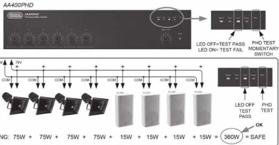
The Limit LED should never be constantly illuminated or damage may occur to the amplifier or sound system. If the Limit LED comes on steadily during use or during the PHD test there are a few common fault conditions to check if using a 70V distributed audio system.
A. Check each speaker setting to make sure it is not set to a 4, 8 or 16 ohm setting. If one speaker is set to one of these settings it will cause a fault condition. A simple and quick way to test this besides visually looking at each speaker is to have a second technician walk the area where the speakers are installed while the PHD test is applied and listen for a speaker that is audibly louder that the other speakers. The louder speaker most likely will be incorrectly tapped and the cause of the fault.
Note: Always take proper hearing precautions.
B. Check each speaker to be sure the load tap is set to the correct power setting. The total power tap selected of all the speakers combined should not exceed the amplifier's maximum power rating or a fault may occur.

Atlas Sound
1601 Jack McKay Blvd. • Ennis, Texas 75119 U.S.A. Telephone: 800.876.3333 • Fax: 800.765.3435
How To Trouble Shoot Your Speaker System If The Limit LED Is Illuminating
C. If the first two check points are OK, there is probably a short in the wiring of the speaker system. Common causes include staples through the wire and the wire cut by metal conduit causing a short to ground.
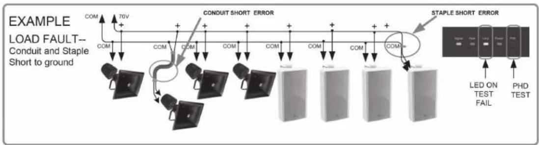
D. Excessive Current Draw - The Limit LED will illuminate Yellow when the amplifier is consuming excessive current. The most likely cause for the fault is an incorrect load impedance connected to the amplifier. The LED should not steadily illuminate if a proper load is applied. Note: An occasional LED flash is okay during standard operation. When LED is ON audible distortion may be heard at the speakers.
E. After finding and correcting the issue, perform the PHD test until the Limit indicator is no longer illuminating.
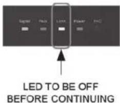
Note: During the initial start of the diagnostic test, the Limit indicator may flash Yellow for a few seconds until an accurate diagnostic reading has been completed, continue to hold the PHD switch in for 5 seconds to assure the test is complete. After 5 seconds and the Limit indicator is illuminating Yellow steadily, stop and read the section "How to Trouble Shoot Your Speaker System If the Limit LED is Illuminating.
Note: For more detailed examples on how to trouble shoot PHD amplifier faults, please visit www.atlassound.com
Connecting a Remote Level Control with Remote Input Select (RIS)
Remote location of a level control can be accomplished via the Remote Level control port. You can control Input 2 or Inputs 4, 5, and 6. The AAPHD series remote level design is based on 10VDC return VCA type topology. Connections to a 10K pot require three conductors, with a minimum of 22 gauge wire, the 10K pot can be placed up to 1000ft away. The return ports can be paralleled together if one pot will control all inputs. Below are Illustrations on different ways to configure a remote level to the AAPHD Series amplifiers.
Example 1 - Using a WPD-VC10K for remote level control.
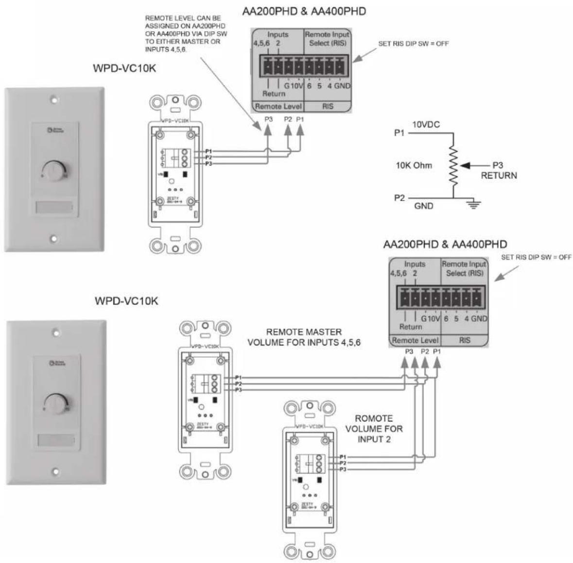
Connecting a Remote Level Control with Remote Input Select (RIS)
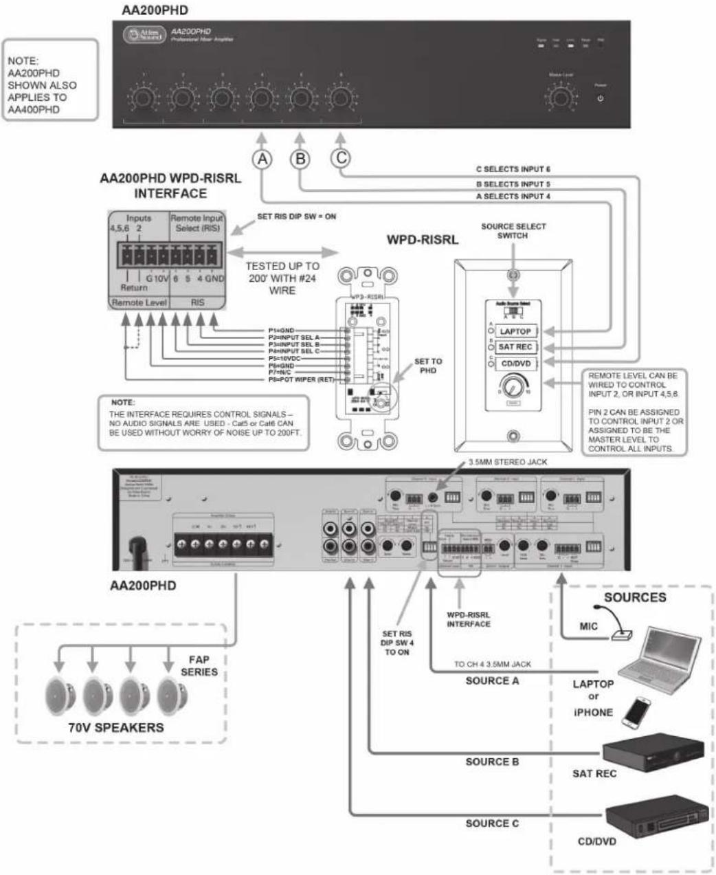
Example 2 - Using a WPD-RISRL (Remote Input Select (RIS) with Remote Level)
The AAPHD Series (Except AA30PHD) features a unique interface for remote selection of 3 inputs without running audio signal from the amplifier. This is ideal because the result is clean audio with no chance of picking up interference. It is intended to be used with the optional wall controller WPD-RISRL from Atlas Sound. The WPD-RISRL allows selection of three inputs (not Input 1) with ability to adjust the level for each input selected. The WPD-RISRL also features an LED that indicates which channel is active. The WPD-RISRL can be placed up to a 1000ft away from the AAPHD amplifier. The WPD-RISRL can be placed up to a 1000ft away from the AAPHD amplifier.
flowchart
graph TD
    A["AA200PHD"] --> B["PROFESSIONAL Power Amplifier"]
    B --> C["AA200PHD WPD-RISRL INTERFACE"]
    C --> D["Remote Input Select (RIS)"]
    D --> E["10V G 10V Return Remote Level RIS"]
    C --> F["TESTED UP TO 200' WITH #24 WIRE"]
    F --> G["P=0ND P2=INPUT SEL A P3=INPUT SEL B P4=INPUT SEL C P5=10VDC P6=GND P7=NC P8=POT WIPER (RET)"]
    C --> H["WPD-RISRL"]
    H --> I["SET TO PHD"]
    I --> J["LAPTOP SAT REC CD/DVD"]
    H --> K["AMOUNT OUT"]
    H --> L["AMOUNT OUT"]
    H --> M["AMOUNT OUT"]
    H --> N["AMOUNT OUT"]
    H --> O["AMOUNT OUT"]
    H --> P["AMOUNT OUT"]
    H --> Q["AMOUNT OUT"]
    H --> R["AMOUNT OUT"]
    H --> S["AMOUNT OUT"]
    H --> T["AMOUNT OUT"]
    H --> U["AMOUNT OUT"]
    H --> V["AMOUNT OUT"]
    H --> W["AMOUNT OUT"]
    H --> X["AMOUNT OUT"]
    H --> Y["AMOUNT OUT"]
    H --> Z["AMOUNT OUT"]
    H --> AA["AMOUNT OUT"]
    H --> AB["AMOUNT OUT"]
    H --> AC["AMOUNT OUT"]
    H --> AD["AMOUNT OUT"]
    H --> AE["AMOUNT OUT"]
    H --> AF["AMOUNT OUT"]
    H --> AG["AMOUNT OUT"]
    H --> AH["AMOUNT OUT"]
    H --> AI["AMOUNT OUT"]
    H --> AJ["AMOUNT OUT"]
    H --> AK["AMOUNT OUT"]
    H --> AL["AMOUNT OUT"]
    H --> AM["AMOUNT OUT"]
    H --> AN["AMOUNT OUT"]
    H --> AO["AMOUNT OUT"]
    H --> AP["AMOUNT OUT"]
    H --> AQ["AMOUNT OUT"]
    H --> AR["AMOUNT OUT"]
    H --> AS["AMOUNT OUT"]
    H --> AT["AMOUNT OUT"]
    H --> AU["AMOUNT OUT"]
    H --> AV["AMOUNT OUT"]
    H --> AW["AMOUNT OUT"]
    H --> AX["AMOUNT OUT"]
    H --> AY["AMOUNT OUT"]
    H --> AZ["AMOUNT OUT"]
    H --> BA["AMOUNT OUT"]
    H --> BB["AMOUNT OUT"]
    H --> BC["AMOUNT OUT"]
    H --> BD["AMOUNT OUT"]
    H --> BE["AMOUNT OUT"]
    H --> BF["AMOUNT OUT"]
    H --> BG["AMOUNT OUT"]
    H --> BH["AMOUNT OUT"]
    H --> BI["AMOUNT OUT"]
    H --> BJ["AMOUNT OUT"]
    H --> BK["AMOUNT OUT"]
    H --> BL["AMOUNT OUT"]
    H --> BM["AMOUNT OUT"]
    H --> BN["AMOUNT OUT"]
    H --> BO["AMOUNT OUT"]
    H --> BP["AMOUNT OUT"]
    H --> BQ["AMOUNT OUT"]
    H --> BR["AMOUNT OUT"]
    H --> BS["AMOUNT OUT"]
    H --> BT["AMOUNT OUT"]
    H --> BU["AMOUNT OUT"]
    H --> BV["AMOUNT OUT"]
    H --> BW["AMOUNT OUT"]
    H --> BX["AMOUNT OUT"]
    H --> BYB["AMOUNT OUT"]
    H --> BZ[BAT/RESET/RESET/RESET/RESET/RESET/RESET/RESET/RESET/RESET/RESET/RESET/RESET/RESET/RESET/RESET/RESET/RESET/RESET/RESET/RESET/RESET/RESET/RESET/RESET/RESET/RESET/RESET/RESET/RESET/RESET/RESET/RESET/RESET/RESET/RESET/RESET/RESET/RESET/RESET/RESET/RESET/RESET/RESET/RESET/RESET/RESET/RESET/RESET/RESET/RESET/REDACT/RESET/RESET/RESET/RESET/RESET/RESET/RESET/RESET/RESET/RESET/RESET/RESET/RESET/RESET/RESET/RESET/RESET/RESET/RESET/RESET/RESET/RESET/RESET/RESET/RESET/RESET/RESET/RESET/RESET/RESET/RESET/RESET/RESET/RESET/RESET/RESET/RESET/RESET/RESET/RESET/RESET/RESET/RESET/RESET/RESET/RESET/RESET/RESET/RESET/ReDACT/SAT/DVD/RIPHONE/SAT REC CD/DVD/RIP Channel / RESET Signal / Switch / TAIR / TAIR
Wiring the AAPHD Series Amplifier
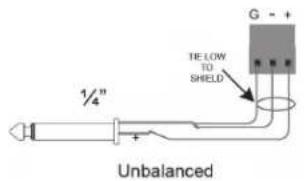
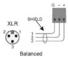
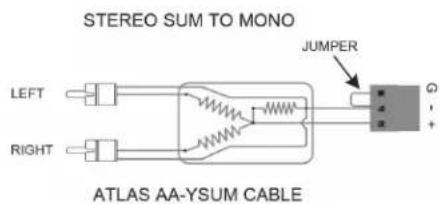
- Mic/Line Input - Use 2 conductor w/ shield for low level signals; 20-22 gauge stranded wire is best. Maintain the proper polarity, + to +, - to -, and shield to ground.
- Unbalanced Inputs and Outputs - Pre-made RCA cables can be purchased from Atlas Sound to simplify interconnection to external devices.
• Zone 2 Out - Use 2 conductor, 20-22 gauge, shielded is best. Terminate the shield at the input to the device if possible. - Speaker Outputs - The AAPHD Series is rated for Class 2 wiring, meaning it is not required to run the wire in conduit. Use Class 2 rated wire, 2 conductor unshielded wire of the appropriate gauge. Contact Atlas SoundTech Support at 1-800-876-3333 for more information on proper wire gauge selection.
Level Control Security Cover Option
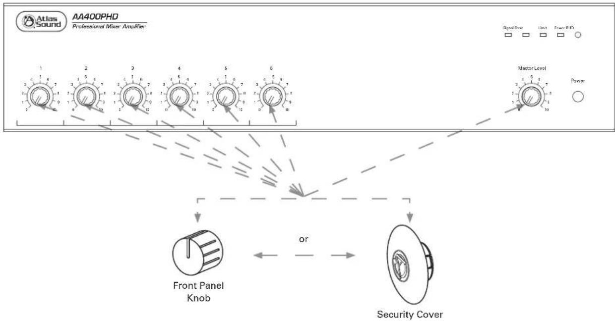
In order to prevent unauthorized operation of the AAPHD Series amplifiers, optional security covers are available which take the place of the front panel knobs. After the amp has been installed and is operating as desired, grasp the front panel knobs and pull straight out from the front panel. Replace the knobs with security covers, Atlas Sound part number AAVCC-5, available in quantities of 5.
flowchart
graph TD
    A["1"] --> B["2"]
    B --> C["3"]
    C --> D["4"]
    D --> E["5"]
    E --> F["6"]
    F --> G["Master Level"]
    G --> H["Power"]
    I["Front Panel Knob"] --> J["Security Cover"]
    K["Power"] --> L["Power"]

Atlas Sound
1601 Jack McKay Blvd. • Ennis, Texas 75119 U.S.A. Telephone: 800.876.3333 • Fax: 800.765.3435
Block Diagram
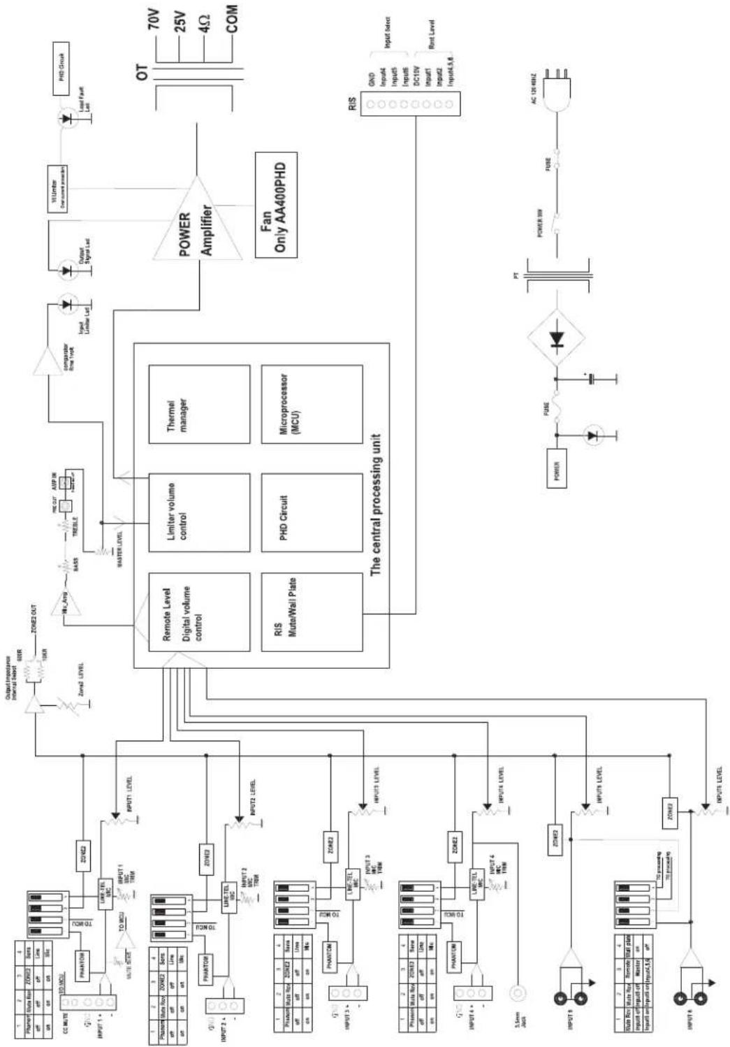
flowchart
graph TD
    A["Power Input"] --> B["Zone 1"]
    B --> C["Zone 2"]
    C --> D["Zone 3"]
    D --> E["Zone 4"]
    E --> F["Zone 5"]
    F --> G["Zone 6"]
    G --> H["Zone 7"]
    H --> I["Zone 8"]
    I --> J["Zone 9"]
    J --> K["Zone 10"]
    K --> L["Zone 11"]
    L --> M["Zone 12"]
    M --> N["Zone 13"]
    N --> O["Zone 14"]
    O --> P["Zone 15"]
    P --> Q["Zone 16"]
    Q --> R["Zone 17"]
    R --> S["Zone 18"]
    S --> T["Zone 19"]
    T --> U["Zone 20"]
    U --> V["Zone 21"]
    V --> W["Zone 22"]
    W --> X["Zone 23"]
    X --> Y["Zone 24"]
    Y --> Z["Zone 25"]
    Z --> AA["Zone 26"]
    AA --> AB["Zone 27"]
    AB --> AC["Zone 28"]
    AC --> AD["Zone 29"]
    AD --> AE["Zone 30"]
    AE --> AF["Zone 31"]
    AF --> AG["Zone 32"]
    AG --> AH["Zone 33"]
    AH --> AI["Zone 34"]
    AI --> AJ["Zone 35"]
    AJ --> AK["Zone 36"]
    AK --> AL["Zone 37"]
    AL --> AM["Zone 38"]
    AM --> AN["Zone 39"]
    AN --> AO["Zone 40"]
    AO --> AP["Zone 41"]
    AP --> AQ["Zone 42"]
    AQ --> AR["Zone 43"]
    AR --> AS["Zone 44"]
    AS --> AT["Zone 45"]
    AT --> AU["Zone 46"]
    AU --> AV["Zone 47"]
    AV --> AW["Zone 48"]
    AW --> AX["Zone 49"]
    AX --> AY["Zone 50"]
    AY --> AZ["Zone 51"]
    AZ --> BA["Zone 52"]
    BA --> BB["Zone 53"]
    BB --> BC["Zone 54"]
    BC --> BD["Zone 55"]
    BD --> BE["Zone 56"]
    BE --> BF["Zone 57"]
    BF --> BG["Zone 58"]
    BG --> BH["Zone 59"]
    BH --> BI["Zone 60"]
    BI --> BJ["Zone 61"]
    BJ --> BK["Zone 62"]
    BK --> BL["Zone 63"]
    BL --> BM["Zone 64"]
    BM --> BN["Zone 65"]
    BN --> BO["Zone 66"]
    BO --> BP["Zone 67"]
    BP --> BQ["Zone 68"]
    BQ --> BR["Zone 69"]
    BR --> BS["Zone 70"]
    BS --> BT["Zone 71"]
    BT --> BU["Zone 72"]
    BU --> BV["Zone 73"]
    BV --> BW["Zone 74"]
    BW --> BX["Zone 75"]
    BX --> BY["Zone 76"]
    BY --> BZ["Zone 77"]
    BZ --> CA["Zone 78"]
    CA --> CB["Zone 79"]
    CB --> CC["Zone 80"]
    CC --> CD["Zone 81"]
    CD --> CE["Zone 82"]
    CE --> CF["Zone 83"]
    CF --> CG["Zone 84"]
    CG --> CH["Zone 85"]
    CH --> CI["Zone 86"]
    CI --> CJ["Zone 87"]
    CJ --> CK["Zone 88"]
    CK --> CL["Zone 89"]
    CL --> CM["Zone 90"]
    CM --> CN["Zone 91"]
    CN --> CO["Zone 92"]
    CO --> CP["Zone 93"]
    CP --> CQ["Zone 94"]
    CQ --> CR["Zone 95"]
    CR --> CS["Zone 96"]
    CS --> CT["Zone 97"]
    CT --> CU["Zone 98"]
    CU --> CV["Zone 99"]
    CV --> CW["Zone 100"]

    subgraph Power Amplifier
        D
        E
        F
        G
        H
        I
        J
        K
        L
        M
        N
        O
        P
        Q
        R
        S
        T
        U
        V
        W
        X
        Y
        Z
        AA
        AB
        AC
        AD
        AE
        AF
        AG
        AH
        AI
        AJ
        AK
        AL
        AM
        AN
        AO
        AP
        AQ
        AR
        AS
        AT
        AU
        AV
        AW
        AX
        AY
        AZ
        BA
        BB
        BC
        BD
        BE
        BF
        BG
        BH
        BI
        BJ
        BK
        BL
        BM
        BN
        BO
        BP
        BPB
        BPB
        BPB
        BPB
        BPB
        BPB
        BPB
        BPB
        BPB
        BPB
        BPB
        BPB
        BPB
        BPB
        BPB
        BPB

    subgraph Fan Only AA400PHD
        D
        E
        F
        G
        H
        I
        J
        K
        L
        M
        N
        O
        P
        Q
        R
        S
        T
        U
        V
        W
        X
        Y
        Z
        AA
        AB
        AC
        AD
        AE
        AF
        AG
        AH
        AI
        AJ, AK, AL, AM, AN, AO, AP, AQ, BB, BC, BD, BE, BF, BG, BH, BI, BJ, BK, BL, BM, BN, PP, PC, PT, PV, PPW, PPWR, PPWR, PPWR, PPWR, PPWR, PPWR, PPWR, PPWR, PPWR, PPWR, PPWR, PPWR, PPWR, PPWR, PPWR, PPWR, PPWR, PPWR, PPWR, PPWR, PPWR, PPWR, PPWR, PPWR, PPWR, PPWR, PPWR, PPWR, PPWR, PPWR, PPWR, PPWR, PPWR, PPWR,
    end

    subgraph Central Processing Unit
        D
        E
        F
        G
        H
        I
        J
        K
        L
        M
        N
        O
        P
        Q
        R
        S
        T
        U
        V
        W
        X
        Y
        Z
        AA
        AB
        AC
        AD
        AE
        AF
        AG
        AH
        AI, AJ, AK, AL, AM, AN, AO, AP, AQ, BB, BC, BD, BE, BF, BG, BH, BP, BPB, BPB, BPB, BPB, BPB, BPB, BPB, BPB, BPB, BPB, BPB, BPB, BPB, BPB, BPB, BPB, BPB, BPB, BPB, BPB, BPB, BPB, BPB, BPB, BPB, BPB, BPB, BPB, BPB, BPB, BPB, BPB, BPB, BPB,
    end

    subgraph Control Unit (Output Impedance Internal Band)
            D1,D2,D3,D4,D5,D6,D7,D8,D9,D10,D11,D12,D13,D14,D15,D16,D17,D18,D19,D20,D21,D22,D23,D24,D25,D26,D27,D28,D29,D30,D31,D32,D33,D34,D35,D36,D37,D38,D39,D40,D41,D42,D43,D44,D45,D46,D47,D48,D49,D50,D51,D52,D53,D54,D55,D56,D57,D58,D59,D60,D61,D62,D63,D64,D65,D66,D67,D68,D69,D70,D71,D72,D73,D74,D75,D76,D77,D78,D79,D80,D81,D82,D83,D84,D85,D86,D87,D88,D89,D90,D91,D92,D93,D94,D95,D96,D97,D98,D99,D100

    %% Note: The chart is a schematic representation of the central processing unit with labels indicating components such as 'Remote Level', 'Thermal manager', 'Microprocessor (MCU)', and 'The central processing unit'.
AA400PHD Specifications
TypeMixerAmplifier
RoHS Compliant Yes
Safety Listings ETL (UL 60065 Standard)
Electrical Specifications
Power Output Max. Average Power @ 50Hz-15kHz with .5% THD, 4Ω 400W RMS
Transformer Outputs 25V 400W RMS
70.7V 400W RMS
4Ω 400W RMS
Front Panel
Power Switch
Push Type
Indicators
Signal, Peak, Limit, Power
PHD Test Circuit
Push Momentary, for 70V Distributed Systems
Level Controls
Master, Inputs 1 - 6
Rear Panel
Inputs
Mic / Line Balanced Qty 4, 3 Position PHX Type. 3.5mm Pitch
Auxiliary Unbalanced Qty 2, RCA
Auxiliary Unbalanced Qty 1, 3.5mm
VOX Sensitivity: Pot Rotary, Range 500uV - 200mV
Remote Mute: Contact Closure, 2 Position Phoenix, 3.5mm Pitch
Remote Level
Type
10V DCV Return
Connector
4 Position Phoenix 3.5mm Pitch
Control Port
Input 2
Control Port
Input 4, 5, 6 or Master
Supply Port
10VDC Send
Ground Port
Ground
Remote Input Select (RIS)
Type
Ground Activated
Connector
4 Position Phoenix 3.5mm Pitch
Inputs Controlled
4,5,6
Control Switch Functions
Zone 2 Assign
Inputs 1, 2, 3, 4
Mute Receive Inputs 1, 2, 3, 4, 5, 6
Phantom Power
Inputs 1, 2, 3, 4
Mic/Line Select
Inputs 1, 2, 3, 4
Remote Level
Assigned Master or Inputs 4, 5, 6
RIS
On/Off

Atlas Sound
1601 Jack McKay Blvd. • Ennis, Texas 75119 U.S.A.
Telephone: 800.876.3333 • Fax: 800.765.3435
AA400PHD Specifications
Outputs
| Main | Transformer Coupled, Balanced, 4Ω, 25V, and 70.7V. Class 2 Rated, Removable 4 Position PHX |
| 5.08mm Pitch, Accepts up to 12 Gauge Wire, 12A Rating | |
| Zone 2 | Unbalanced 600Ω / 10kΩ, Max 1.0V Out, Removable 2 Position PHX 3.5mm Pitch, Accepts Up to 18 Gauge Wire, 8A Rating |
| Pre Out RCA, Unbalanced 150Ω | |
Technical Data
Inputs Total Qty 6
Frequency Response 50Hz-15kHz +/- 3dB
Thd+N 0.5% Or Less, At 1kHz, Rated Output
Input Sensitivity / Impedance Input 1, 2, 3, 4 Mic Mode 5mv, No Trim, 1200Ω
Input 1, 2, 3, 4 Line Mode 316mV (-10dBV) 1200Ω
Input 4 3.5mm Summed, 316mV (-10dBV) 10kΩ
Input 5, 6 RCA Unbalanced Summed 316mV (-10dBV) 10kΩ
| Signal To Noise Ratio | Mic | >55dB |
| Line | >55dB | |
| Telephone | >55dB |
Input 5, 6 >75dB
Phantom Power 24VDC
Power Requirements
| AC Mains | 120V 60Hz |
| AC Cord | 2M, 16 gauge, NEMA 5-20P |
| Idle Power | 0.32A, 38W, 129 BTU |
| Average Power 13 Rated Output | 5.4A, 648W, 2211 BTU |
| Max Power (20mS Burst) | 8.4A, 1008W, 3439 BTI |
Mechanical
| Chassis | Steel |
| Finish | Black Paint on Front and Top |
| Dimensions | 16.54" x 3.66" x 14.6" (420mm x 93mm x 422mm) |
| Weight | 41.6 lbs (15.8kg) |
Notes:
Notes:
Notes:
Limited Warranty
All products manufactured by Atlas Sound are warranted to the original dealer/installer, industrial or commercial purchaser to be free from defects in material and workmanship and to be in compliance with our published specifications, if any. This warranty shall extend from the date of purchase for a period of three years on all Atlas Sound products, including SOUNDOLIER brand, and ATLAS SOUND brand products except as follows: one year on electronics and control systems; one year on replacement parts; and one year on Musician Series stands and related accessories. Additionally, fuses and lamps carry no warranty. Atlas Sound will solely at its discretion, replace at no charge or repair free of charge defective parts or products when the product has been applied and used in accordance with our published operation and installation instructions. We will not be responsible for defects caused by improper storage, misuse (including failure to provide reasonable and necessary maintenance), accident, abnormal atmospheres, water immersion, lightning discharge, or malfunctions when products have been modified or operated in excess of rated power, altered, serviced or installed in other than a workman like manner. The original sales invoice should be retained as evidence of purchase under the terms of this warranty. All warranty returns must comply with our returns policy set forth below. When products returned to Atlas Sound do not qualify for repair or replacement under our warranty, repairs may be performed at prevailing costs for material and labor unless there is included with the returned product(s) a written request for an estimate of repair costs before any nonwarranty work is performed. In the event of replacement or upon completion of repairs, return shipment will be made with the transportation charges collect.
EXCEPT TO THE EXTENT THAT APPLICABLE LAW PREVENTS THE LIMITATION OF CONSEQUENTIAL DAMAGES FOR PERSONAL INJURY, ATLAS SOUND SHALL NOT BE LIABLE IN TORT OR CONTRACT FOR ANY DIRECT, CONSEQUENTIAL OR INCIDENTAL LOSS OR DAMAGE ARISING OUT OF THE INSTALLATION, USE OR INABILITY TO USE THE PRODUCTS. THE ABOVE WARRANTY IS IN LIEU OF ALL OTHER WARRANTIES INCLUDING BUT NOT LIMITED TO WARRANTIES OF MERCHANTABILITY AND FITNESS FOR A PARTICULAR PURPOSE.
Atlas Sound does not assume, or does it authorize any other person to assume or extend on its behalf, any other warranty, obligation, or liability. This warranty gives you specific legal rights and you may have other rights which vary from state to state.
Service
Should your AA400PHD require service, please contact the Atlas Sound warranty department at 1-877-689-8055, ext. 277 or support.atlassound.com to obtain an RA number.
Atlas Sound Tech Support can be reached at 1-800-876-3333 or support.atlassound.com.
Visit our website at www.AtlasSound.com to see other Atlas products.
©2016 Atlas Sound L.P. All rights reserved. Atlas Sound is a trademark of Atlas Sound L.P. All other trademarks are the property of their respective owners. ATS004886 RevD 4/16

- Atlas Sound
- AA400PHD 400W Mixer Amplifier
- Important Safety Instructions
- WARNING
- - 3 - AtlasSound.com
- THAWARNING Use
- CAUTION When Installing The Product
- CAUTION When The Product Is In Use
- Introduction
- Key Features
- Applications
- Power Switch
- Power Indicator
- Signal Indicator
- Peak Indicator
- Limit Indicator
- PHD Switch
- Front Panel
- Input 1-6 Level
- Master Level
- Rear Panel
- Bass Control
- Treble Control
- Input 1
- Remote Mute Connector
- VOX Mute Sensitivity Control
- Mic Trim
- Multi Function DIP Switch Input 1
- Switch A
- Inputs 2 & 3
- Mic Trim Inputs 2 & 3
- Multi Function DIP Switch Inputs 2 & 3
- Input 4
- Mic Trim
- Multi Function DIP Switch Input 4
- Input 5
- Input 6
- Multi Function DIP Switch Inputs 5 & 6 and Remote
- Zone 2 Output Port
- Zone 2 Output Level Control
- Remote Input Select (RIS) Port
- Remote Level Control Port
- Pre Out
- Amp In
- Amplifier Outputs
- Power Cord
- Ground Terminal
- Using the PHD Mixer Amplifier Diagnostic System
- Common Amplifier Failure Conditions, also see "How to Trouble Shoot Your Speaker System if the Limit LED is Illuminating".
- Running a Self-Diagnostic Test using the PHD Feature
- How To Trouble Shoot Your Speaker System If The Limit LED Is Illuminating
- Connecting a Remote Level Control with Remote Input Select (RIS)
- Wiring the AAPHD Series Amplifier
- Level Control Security Cover Option
- AA400PHD Specifications
- Electrical Specifications
- Remote Level
- Remote Input Select (RIS)
- Control Switch Functions
- Outputs
- Technical Data
- Power Requirements
- Mechanical
- Limited Warranty
- Service
Brand : Atlas Sound
Model : AA400PHD
Category : Blender