AA120 - Blender Atlas Sound - Free user manual and instructions
Find the device manual for free AA120 Atlas Sound in PDF.


| Product Type | Blender |
| Brand | Atlas Sound |
| Model | AA120 |
| Dimensions (W x D x H) | 20 cm x 20 cm x 40 cm |
| Weight | 2.5 kg |
| Power Consumption | 600 W |
| Jar Capacity | 1.5 L |
| Jar Material | Plastic |
| Blade Material | Stainless Steel |
| Speed Settings | 2 speeds + pulse |
| Power Cord Length | 1.2 m |
| Safety Features | Auto shut-off, non-slip feet |
| Dishwasher Safe Parts | Jar, lid, blade assembly |
| Cleaning Method | Detachable parts dishwasher safe; wipe base with damp cloth |
| Spare Parts Available | Jar, lid, blade assembly, gasket |
| Warranty | 1 year |
| Repairability | Spare parts available; base unit not user-serviceable |
Frequently Asked Questions - AA120 Atlas Sound
User questions about AA120 Atlas Sound
0 question about this device. Answer the ones you know or ask your own.
Ask a new question about this device
Download the instructions for your Blender in PDF format for free! Find your manual AA120 - Atlas Sound and take your electronic device back in hand. On this page are published all the documents necessary for the use of your device. AA120 by Atlas Sound.
USER MANUAL AA120 Atlas Sound
AA120/AA240 Atlas Sound Mixer Amplifi er
TABLE OF CONTENTS
Safety Instructions....2
Introduction, Features, and Applications....3
Safety Precautions....4
Front Panel Description....6
Rear Panel Description....7
Quick Start Examples....13
Wiring the AA120/AA240....16
Rack Mount Kit....18
Block Diagram....19
Optional Input Transformer Installation....20
Specifications....21
Warranty....24
SAFETY INSTRUCTIONS
Please be sure to read all the instructions carefully before using this product.
- Many safety messages are included in this manual, please be sure to observe these as they are important.
• We recommend that you keep this manual close by for future reference. - Do not install this device in dusty or humid locations, or in direct exposure to sunlight. In addition, locations that have steam or sooty conditions are not to be used, as this may result in fire or electric shock.
- Prevent the power cord from damage, pinching or being walked on, in particular, the plug and where the cord attaches to the amplifier.
- Do not defeat the polarized or grounding feature of the power cord plug. If the plug will not fit in your outlet, consult a licensed electrician.
- Use only the accessories and attachments specified in this manual.
- Disconnect the power cord during electrical storms, or when the product will be unused for long periods.
- Have servicing done only by qualified personnel. Servicing will be required when the product is damaged in any way, when the power cord is damaged, when liquid has been spilled or objects have fallen into the device. Servicing will also be required when this device has been exposed to rain, does not operate normally, or has been dropped.
Specifications are subject to change without notice

Atlas Sound
AtlasSound.com
1601 JACK MCKAY BOULEVARD ENNIS, TEXAS 75119 U.S.A. • TELEPHONE: (800) 876-3333 • FAX: (800) 765-3435
©2006 ATLAS SOUND LP Printed in U.S.A. 000106 ATS002187 RevA 01/06 PP
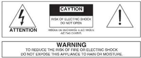
The lighting flash with arrowhead within a triangle is intended to tell the user that parts inside the product are a risk of electric shock to persons.
The exclamation point within a triangle is intended to tell the user that important operating and servicing instructions are in the papers with the appliance.
INTRODUCTION
Congratulations and thank you for purchasing the Atlas Sound Model AA120/AA240 professional grade mixer/amplifi er. An integral part of the AA Series of commercial products, the AA120/AA240 was engineered and integrated with unique features to assist the contractor/installer in today's commercial business audio environment.
FEATURES
• Zone 1 output 120W (AA120), 240W (AA240)
• Zone 2 output 1W@ 8Ω or 1.5V@ 600Ω
- Inputs 1-5 mic/line switchable
- Input 6 line level only
- Input 1 has VOX send
- Inputs 2-6 have switch selectable mute receive
• 2 Tape and 2 Line outputs
- Remote VCA selectable INPUT 6 or MASTER
- Switch selectable bridge in/out bus allows amplifi er combining
• Pre amp out-Power amp in loop
APPLICATIONS
The AA120/AA240 will be right at home in large retail, commercial, and industrial paging and background music applications. Hotels and conference centers will appreciate the room combining and remote volume control features that this product provides.
SAFETY PRECAUTIONS
- Read the instructions very carefully before using this product.
- Observe the instructions in this manual as conventions of safety; symbols and messages regarded as important precautions are included.
- Retain this manual for future reference.
Message Conventions and Safety Symbols
Before installing and operating this product, read this manual so you are fully aware of the potential safety hazards and understand the safety symbols and messages. The safety symbols and messages shown below are used in this manual to prevent bodily injury and property damage from mishandling.

WARNING
Indicates a potentially hazardous situation which, if mishandled, could result in death or serious injury.

CAUTION
Indicates a potentially hazardous situation which, if mishandled, could result in moderate or minor personal injury, and/or property damage.

WARNING
WHEN INSTALLING THE PRODUCT
- Do not expose the product to rain or in an environment where it may be exposed to water or other liquids, which may result in fire or electric shock.
- Operate the product only with the voltage specified on the unit. Fire and/or electric shock may result if a higher voltage is used.
- Do not modify, kink, or cut the power cord. Do not place the power cord on close proximity to heaters and do not place heavy objects on the power cord, including the product itself, doing so may result in fire or electric shock.
- Replace the protective cover over the speaker terminals after installation. Do not touch the 70V speaker terminals as electric shock may result.
- Ensure that the safety ground terminal is connected to a proper ground. Never connect the ground to a gas pipe as a catastrophic disaster may result.
- Be sure the installation of the product is stable, avoid slanted surfaces as the product may fall and cause injury or property damage.

WARNING WHEN THE DEVICE IS IN USE
- To prevent electric shock, do not remove the product cover as there are high voltage components inside. Refer all servicing to Atlas Sound.
- Should any of the following irregularities occur during use, immediately switch off the power, disconnect the power cord from the AC outlet contact Atlas Sound. Do not to attempt to continue operation with the product as this may cause fire or electric shock.
- Smoke or strange smell coming from the unit.
- If the product falls or the case is damaged.

Specifications are subject to change without notice
Atlas Sound
AtlasSound.com
1601 JACK MCKAY BOULEVARD ENNIS, TEXAS 75119 U.S.A. • TELEPHONE: (800) 876-3333 • FAX: (800) 765-3435
©2006 ATLAS SOUND LP Printed in U.S.A. 000106 ATS002187 RevA 01/06 PP
- If water or any metallic objects falls, into the product.
- If the power supply cord is damaged in any way.
- If the unit is malfunctioning.
- Do not insert or drop metallic objects or fl ammable materials into the ventilation holes of the product's cover, as this may result in electric shock or fi re.
- Do not place any containers with liquid or metallic objects on the top of the product. If any liquid spills into the unit, fi re or electric shock may result.
- Never operate this product or touch the power supply cord during an electrical storm, electric shock may result.
- Never exceed the wattage on the product when connecting equipment. Fire and or property damage may result.

CAUTION WHEN INSTALLING THE PRODUCT
- Plugging in or unplugging the power cord with wet hands may result in electric shock.
- Never move the unit with the power cord plugged into the wall, as damage to the power cord may result. When unplugging the cord from the wall, grasp the plug, NOT the cord.
- Never block the panel vents in the product's cover. Heat buildup may result inside the unit and fire may result.
- Never install this product in humid or dusty locations, nor in direct sunlight, near sources of heat, or in areas where sooty smoke or steam in present. Fire and electric shock may result.

CAUTION WHEN THE PRODUCT IS IN USE
- When powering the product up for the first time, ensure that the volume controls are turned down. Unexpected high sound pressure levels may be present at the speakers and result in hearing loss.
- Never place heavy objects on the product, causing it to fall and or break, resulting in personal injury and property damage. In addition, the product itself may fall and cause injury and property damage.
- Never operate the product for extended periods with the sound in a distorted condition. This is an indication of a malfunction, which may result in excessive heat being generated and causing a fire.
- Contact Atlas Sound for instructions on cleaning the inside of the unit. Large accumulations of dust inside the unit may result in heat buildup and fire.
- Ensure that the power supply plug in securely plugged into the wall outlet. Never allow dust to accumulate on the power plug or inside the wall outlet.
- When cleaning the unit or the unit is not to be operated for an extended time period, unplug the power cord from the wall.

Specifications are subject to change without notice
Atlas Sound
AtlasSound.com
1601 JACK MCKAY BOULEVARD ENNIS, TEXAS 75119 U.S.A. • TELEPHONE: (800) 876-3333 • FAX: (800) 765-3435
©2006 ATLAS SOUND LP Printed in U.S.A. 000106 ATS002187 RevA 01/06 PP
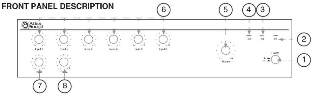
1. Power Switch
This push on/push off switch applies power to the AA120/AA240.
2. Power LED
This LED will illuminate when the AA120/AA240 is turned on.
3. Peak LED
The PEAK LED will illuminate when the AA120/AA240 is in a clipping condition, caused by excessively high input levels or a GAIN control is turned up too high. An occasional flash is OK.
4. Signal LED
This LED will assist you in setting gain structure into the amp. With a source connected to the amp and playing, turn up the channel gain control until this LED just starts to flash. Once all the sources connected are playing, the SIGNAL LED may be on solid. This condition is normal.
5. Master Gain Control
The MASTER GAIN CONTROL will raise or lower all the input channels together. A good starting point for setting gain structure is to set MASTER GAIN CONTROL at the 12:00 position, and then adjust the individual channels one at a time.
6. Input 1-6 Controls
The gain for input channels 1-6 are controlled by these rotary controls. The MASTER GAIN CONTROL must be turned up in addition to the input controls for audio to be present at the speaker terminals.
7. Bass Control
The BASS CONTROL is a shelving type control which will boost or cut bass frequencies at 100Hz at the rate of ±10dB.
8. Treble Control
The TREBLE CONTROL is a shelving type control which will boost or cut treble frequencies at 10kHz at the rate of ±10dB.

Specifications are subject to change without notice
Atlas Sound
AtlasSound.com
1601 JACK MCKAY BOULEVARD ENNIS, TEXAS 75119 U.S.A. • TELEPHONE: (800) 876-3333 • FAX: (800) 765-3435
©2006 ATLAS SOUND LP Printed in U.S.A. 000106 ATS002187 RevA 01/06 PP
REAR PANEL DESCRIPTION
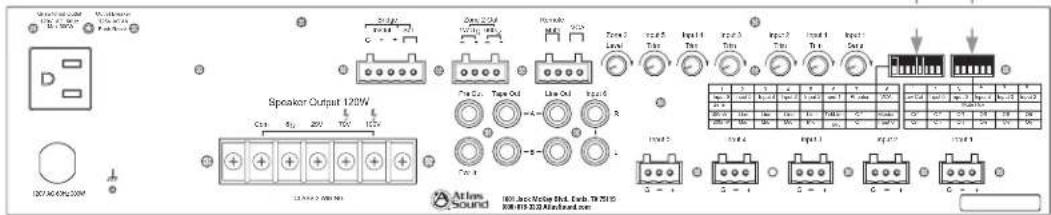
9. Dipswitch "A" Positions 1-6
Understanding the functionality of the dipswitches is key to getting the most out of the AA120/AA240. Whether the switch is in the "Up" or "Down" position is critical to the function of the amplifier. Note: Mispositioning any of these switches may cause harm to the speakers or amplifi er. We recommended all levels be turned down prior to making any switch selections. Pay close attention to the two assignment charts and manual for proper settings.
| 1 | 2 | 3 | 4 | 5 | 6 |
| Low Cut | Input 6 | Input 5 | Input 4 | Input 3 | Input 2 |
| Mule Rcv | |||||
| Off | Off | Off | Off | Off | Off |
| On | On | On | On | On | On |
Dipswitch 1- LOW CUT – When in the "ON" position, frequencies below 400Hz are attenuated at the rate of 6dB per octave. Note: The rotary bass control is bypassed when the LOW CUT fi Iter is on. We suggest that when paging horns are connected to the AA120/AA240, engage the LOW CUT filter to prevent the horns from operating below their cut off frequency. When "OFF", the amplifi er operates full bandwidth.
Dipswitch 2-6 - MUTE RCV (RECEIVE) – When "ON", Input's 2-6 signals will be muted upon a signal present on Input 1 (Refer to Number 11 Input 1 Sens), or a contact closure on the remote mute terminals (Refer to Number 15 Remote Mute).
10. Dipswitch "B" Positions 1-8
| 1 | 2 | 3 | 4 | 5 | 6 | 7 | 8 |
| Input 6 | Input 5 | Input 4 | Input 3 | Input 2 | Input 1 | Phantom | VCA |
| Sens | |||||||
| 100mV | Line | Line | Line | Line | Tel/Line | Off | Master |
| 300mV | Mic | Mic | Mic | Mic | Mic | On | Input 6 |
Dipswitch 1 – When set to the "100mV" position, the sensitivity of Input 6 is suitable for inputting Telephone Paging Signals. When set to the "300mV" position, the sensitivity of Input 6 is suitable for CD/DVD player outputs.
Dipswitch 2-5 - When set to the "Line" position, input sensitivity is suitable for CD/DVD line level outputs. When set to the "Mic" position, sensitivity is suitable for microphone inputs.

Specifications are subject to change without notice
Atlas Sound
AtlasSound.com
1601 JACK MCKAY BOULEVARD ENNIS, TEXAS 75119 U.S.A. • TELEPHONE: (800) 876-3333 • FAX: (800) 765-3435 ©2006 ATLAS SOUND LP Printed in U.S.A. 000106 ATS002187 RevA 01/06 PP
| 1 | 2 | 3 | 4 | 5 | 6 | 7 | 8 |
| Input 6 | Input 5 | Input 4 | Input 2In | Indap8t 1 | Phantom | VCA | |
| Sens | |||||||
| 100mV | Line | Line | Line | Line | Tel/Line | Off | Master |
| 300mV | Mic | Mic | Mic | Mic | Mic | On | Input 6 |
Dipswitch 6 - When set the "Tel/Line" position, Input 1 sensitivity is suitable for telephone paging and line level signals. When set to the "Mic" position, the sensitivity is set for microphone signals.
Dipswitch 7 - When set to the "OFF" position, PHANTOM POWER is turned off on INPUTS 1-5. When set to the "ON" position, PHANTOM POWER (24VDC) is available on INPUTS 1-5 (mic position only).
Dipswitch 8 - When set to the "Master" position, the VCA control port acts as a over all system remote volume control, adjusting all the input channels present on the master section mix bus up or down simultaneously. When set to the "Input 6" position, the VCA remote control port affects only the level of INPUT 6.
11. Input 1 Sens
This control adjusts how sensitive the mute send circuitry on INPUT 1 reacts. Setting the control fully counter-clockwise will lower the sensitivity, and a higher amplitude signal will be required at INPUT 1 to trigger the mute send circuits. Fully clockwise will raise the sensitivity of the mute circuits, where a lower amplitude signal will trigger a mute send. Careful calibration of this control may be required to fully utilize the mute circuits' capabilities. Adjustment of this control should occur after the input trim (12) for channel 1 is set.
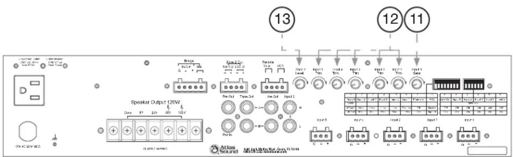
12. Inputs 1-5 Trim
These variable controls allows fi ne tuning of the gain of INPUTS 1 – 5. There is 20dB of variable gain available. The trim only applies when the input is set to the "Mic" position on the dipswitch.
13. Zone 2 Level
This rotary control will vary the signal level at the Zone 2 output terminals. Fully counter-clockwise (0) is off; fully clockwise (10) is the maximum output level. The Zone 2 output gets its signal from INPUT 6, volume control.

Specifications are subject to change without notice
Atlas Sound
AtlasSound.com
1601 JACK MCKAY BOULEVARD ENNIS, TEXAS 75119 U.S.A. • TELEPHONE: (800) 876-3333 • FAX: (800) 765-3435
©2006 ATLAS SOUND LP Printed in U.S.A. 000106 ATS002187 RevA 01/06 PP
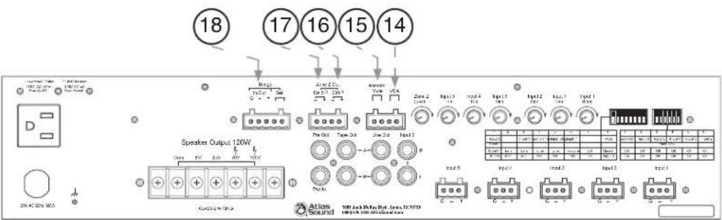
14. VCA
Remote location of the level control can be accomplished via the VCA control port. You can control the overall level (Master) or just Input 6. This selection is made via Dipswitch "B" position #8. Connect the two leads from the optional remote volume control to these terminals. This remote level control is POST Master and Input 5 Level Controls. Set the system's maximum levels using the amplifier level controls and then use the remote VCA potentiometer as an attenuator from the maximum levels set. See the VCA setup section for instructions on wiring the potentiometer.
15. Remote Mute
The Remote Mute feature is useful when the background system needs to be muted from a remote location. When shorting the Remote Mute terminals together, (G) to (M), the assigned channels will be muted. Note: Input 1 cannot be VOX or remote muted at anytime. Dipswitches 2-5 settings determine which inputs are to receive the Mute trigger. To trigger the mute it is common to use an external contact closure or switch on a microphone.
16. Zone 2 Output - 600Ω
The 600Ω 1.5V (Zone 2 Out) output is typically connected to a PBX MUSIC ON HOLD port, also known as MOH. The ZONE 2 output gets its signal from INPUT 6, volume control.
17. Zone 2 Output - 1 Watt 8Ω
The 8Ω 1W Zone 2 output can drive an external 8Ω speaker, and is taken Pre input 6 gain control. Use the 1W 8Ω terminals for connection to an external speaker.
18. Bridge In/Out
Certain installations have the need to combine one or more mixers together. These mixers may be in different rooms of an install but have the need to share a page or music throughout the installation. These terminals provide a way to send and receive balanced line level signals from the internal mix bus of the AA120/AA240. The "BRIDGE IN/OUT" feature is PRE Tone Controls and Low Cut Filter The Bridge In/Out feature allows you to send and receive a balanced signal. This is important for allowing longer distances between the mixers. Note: This function should only be used with other Atlas Sound mixers that have this feature. The Send and Receive signals are combined through the same terminals. To activate this feature, see number 19 Bridge Select.
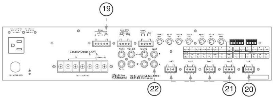
19. Bridge Select
The "Bridge Select (Sel)" terminals are the access point to activate the "Bridge In/Out" feature. To activate the feature connect the two points together via an external contact closure. These two points must be connected to send or receive any signal. By connecting the Bridge In/Out terminals of two AA120/AA240's, a simple room combining system can be accomplished. If using a remote switch and closing it, the "Bridge Select (Sel)" will combine the amps as one, opening the switch will separate the two amps. Note: If combining 3 or 4 mixers together the output level will have to be adjusted before and after Bridge Sel terminals are connected (shorted) together. We suggest utilizing the Remote Level control when using this feature.
| 1 | 2 | 3 | 4 | 5 | 6 | 7 | 8 |
| Input 6 | Input 5 | Input 4 | Input 3 | Input 2 | Input 1 | Phantom | VCA |
| Sens | |||||||
| 100mV | Line | Line | Line | Line | Tel/Line | Off | Master |
| 300mV | Mic | Mic | Mic | Mic | Mic | On | Input 6 |
20. Input 1
Balanced mic or line level signals connect to the (+) (−) and (G) terminals. Refer to the chart above "Multi Function Dipswitch" for the following setting. Dipswitch 6, labeled Input 1 must be set to the proper position for mic or Tel/Line level. If you are connecting an unbalanced line level input, tie (short) the (G) and (−) terminals together. An optional Input Isolation Transformer is available if a ground loop problem exists. See page 20 for transformer installation. Contact Atlas for more details on the Input Isolation Transformer.
Note: Input 1 cannot be muted from other channels. This channel is the VOX mute send to the other inputs that are set to Mute Receive. The sensitivity and threshold for the VOX send works in conjunction with the Input 1 Trim and the Input 1 Sens.
21. Inputs 2-5
Inputs 2-5 are balanced, line or mic level (Refer to Dipswitch Bank 1-8 for setting input sensitivity). For wiring unbalanced inputs, tie (short) the (G) and (−) terminals together.
22. Input 6
INPUT 6 consists of a pair of stereo summing, line level inputs. Connect unbalanced audio outputs here such as CD players or audio from DVD players.

Specifications are subject to change without notice
Atlas Sound
AtlasSound.com
1601 JACK MCKAY BOULEVARD ENNIS, TEXAS 75119 U.S.A. • TELEPHONE: (800) 876-3333 • FAX: (800) 765-3435 ©2006 ATLAS SOUND LP Printed in U.S.A. 000106 ATS002187 RevA 01/06 PP

23. Line Out A/B
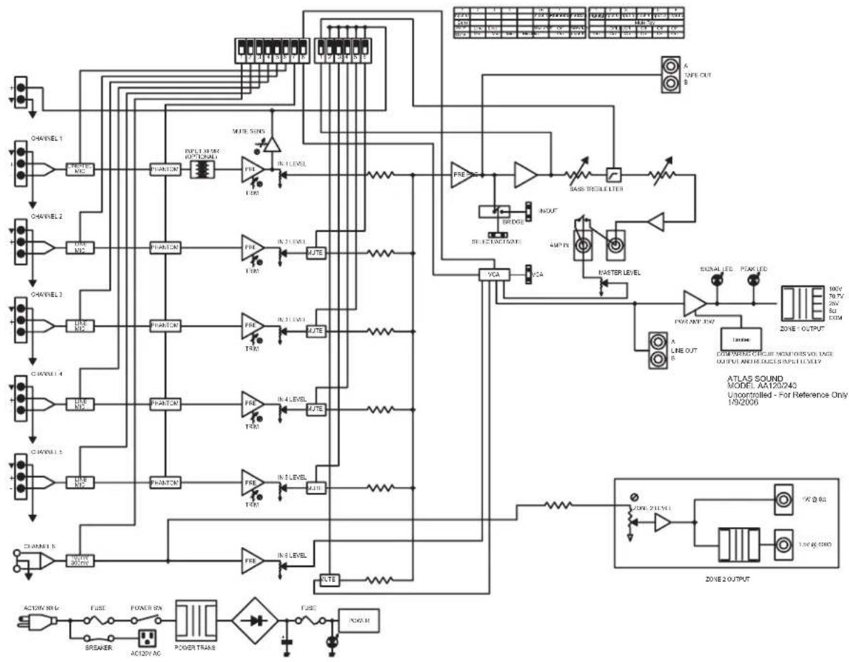
The LINE OUT connector is useful for providing unbalanced line level signal to another amplifier or other external devices. Prior to using this feature one must understand where the internal signal pick up point is so you can decide if it is correct for your application. We suggest you refer to the block diagram of the AA120/AA240 to have a complete understanding of the signal flow.
Note the following conditions for LINE OUT
A. Pre Low Cut Filter
B. Post Tone Controls (meaning the settings for the Bass and Treble controls affect this signals output). Note: Refer to "Low Cut Filter Switch for complete understanding of the LCF feature.
C. Post Amp In (meaning any signal that is inserted into the Pre AMP In jack will be present at the Line Out).
24. Tape Out A/B
Line level mono signals are available at this jack for connection to recording devices. The signal available here is PRE tone control and low cut filter and comes from the internal mix bus.
25. Pre Out
The PRE OUT connector has Post tone control signals available to drive another power amp or external audio devices. Use in conjunction with the AMP IN connector, an effects loop can be created by connecting the PRE OUT jack to a device such as an equalizer then back out to the AMP IN connector. See the connection diagram in the setup section of this manual.
26. Pwr In
The AMP IN connector is useful for converting the AA120/AA240 into a slave amp. When a line level signal is connected to this input, the internal connection between the preamp and internal power amp is broken. The AA120/AA240 is now just a power amplifier, amplifying audio signals applied to this connector.

Specifications are subject to change without notice
Atlas Sound
AtlasSound.com
1601 JACK MCKAY BOULEVARD ENNIS, TEXAS 75119 U.S.A. • TELEPHONE: (800) 876-3333 • FAX: (800) 765-3435 ©2006 ATLAS SOUND LP Printed in U.S.A. 000106 ATS002187 RevA 01/06 PP
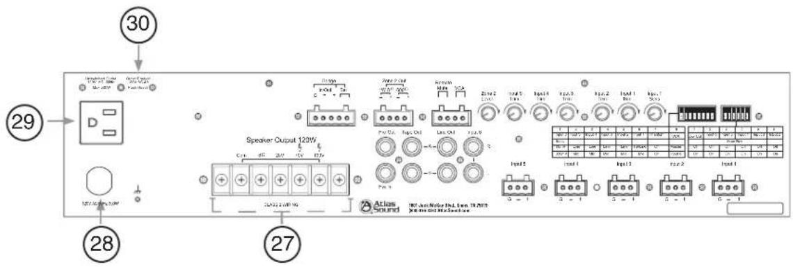
27. Speaker Terminals
For loudspeaker connections, connect using the following information or proceed to the setup section for typical wiring diagrams.
COM - Speaker common or negative connection
8 Ω - Connect to direct coupled loudspeakers
25V - Connect to transformer coupled, 25V loudspeakers with a total load impedance of no less than 5.2Ω for the AA120 or 2.6Ω for the AA240.
70V - Connect to transformer coupled, 70.7V loudspeakers with a total load impedance of no less than 41.6Ω for the AA120 or 21Ω for the AA240.
100V - Connect to transformer coupled, 100V loudspeakers with a total load impedance of no less than 83Ω for the AA120 or 41.6Ω for the AA240.
28. Power Cord
Connect the power cord to 120VAC only. Serious damage may result if accidentally connected to other line voltages.
29. Unswitched Outlet
The 120VAC outlet is energized at all times when the AA120/AA240 power cord is connected to a live duplex outlet. Useful for connecting Atlas work lights, etc. Keep the total power draw below 500W (AA120) or 750W (AA240).
30. Circuit Breaker – Unswitched Outlet
The circuit breaker is designed to trip and shut down the AA120/AA240 "Unswitched Outlet" upon an over current condition. After correcting the cause of the breaker tripping, reset the breaker by pushing in on the tab.
QUICK START EXAMPLES
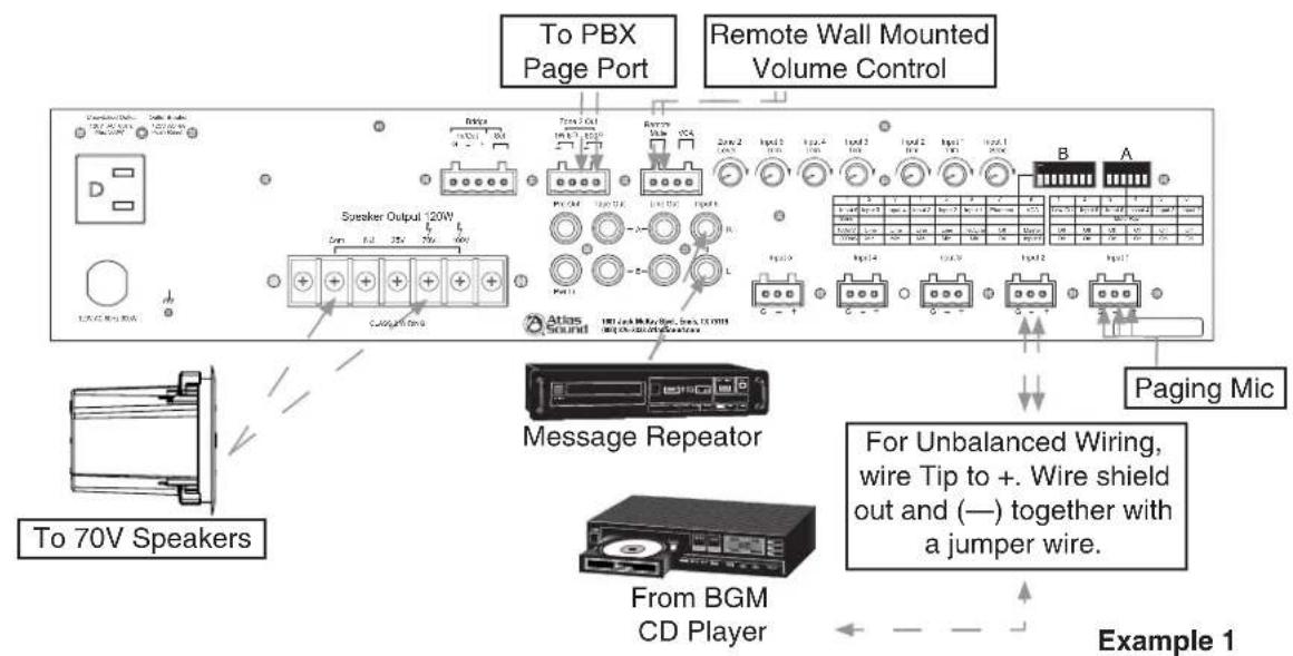
Example 1 — System Paging, BGM, and MOH with Remote Master Level Control
This application has the paging microphone into INPUT 1, BGM (CD player) into Input 2, and a Message Repeater or MOH into Input 6. The Zone 2 Output is sent to the telephone system's MOH input port. A level control is placed in another area such as a front desk to adjust the system's level without having to go the equipment room. When a page comes through Input 1, the BGM is muted allowing only paging to be heard through the main system. The MOH is not affected during the page.
- Connect a paging mic to INPUT 1. Set Dipswitch "B" #6, "Input 1" to the "Mic" position. Note: The INPUT 1 Trim and Sens will need to be adjusted after all the settings and connections have been set.
- Connect a BGM (CD) player to INPUT 2.
- Set Dipswitch "A" #6, "Mute Rcv" to the "ON" position.
- Connect a Message Repeater or MOH device to INPUT 6. Note: The input gain of this channel may need to be change for proper level balance. Dipswitch "B" #1, "Input 6" allows you to select between a 100mV or 300mV input sensitivity. Turn down channel 6 gain control on the front panel.
- Connect Zone 2 output to the MOH input on your telephone. Adjust the Zone 2 Output level as needed.
- Connect a wall mount volume control (Atlas p/n AAVCC-10K) to the terminals marked "VCA". Set Dipswitch "B" #8, "VCA" to "Master".
Dipswitch Settings
Dipswitch 1 - Off (Set To The Required Gain) Dipswitch 2 - Off (Not Affected)
Dipswitch 3 - Off (Not Affected) Dipswitch 4 - Off (Not Affected)
Dipswitch 5 - Off (Line) Dipswitch 6 - On (Mic)
Dipswitch 7 - Depends On Mic Type Dipswitch 8 - Master

Specifications are subject to change without notice
Atlas Sound
AtlasSound.com
1601 JACK MCKAY BOULEVARD ENNIS, TEXAS 75119 U.S.A. • TELEPHONE: (800) 876-3333 • FAX: (800) 765-3435 ©2006 ATLAS SOUND LP Printed in U.S.A. 000106 ATS002187 RevA 01/06 PP
Example 2 - Hotel Room Combining Using Two AA120s/AA240s
This example utilizes the combining feature of the Atlas AA120/AA240 mixer amplifiers. The drawing below shows the equipment connections for two hotel ballrooms, separated by a moveable air wall. The hotel needs to be able to have the audio system operate as one large unit (air wall open) or two discreet systems (air wall closed). As indicated in the example, a BGM CD player is shared between the two AA120s/AA240s, via a "Y" cable, connected to input 6 of each mixer amp. The Bridge terminals of both amplifiers are connected together, through a DPST switch that makes (combines) or breaks (separates) the Bridge connections between the amplifiers. When the switch is closed, any audio signal into either amp will be present at both amplifier's speaker outputs. A volume control and DPST switch (see drawing for clarity) controls the background music level and turns the music on or off in each room. For emergency evacuation purposes, a signal from the hotel's fire alarm system is connected to channel 1 of both amplifiers, with the mute sensitivity adjusted as needed. All other channels are set for mute receive and will mute when the siren tone is present on channel 1.
Dipswitch Settings
Dipswitch "A" 1-6
2-6 - On
Dipswitch "B" 1-8
Dipswitch 1 - (Set To The Required
Gain
Dipswitch 2 - "Mic
Dipswitch 3 - "Mic"
Dipswitch 4 - "Mio
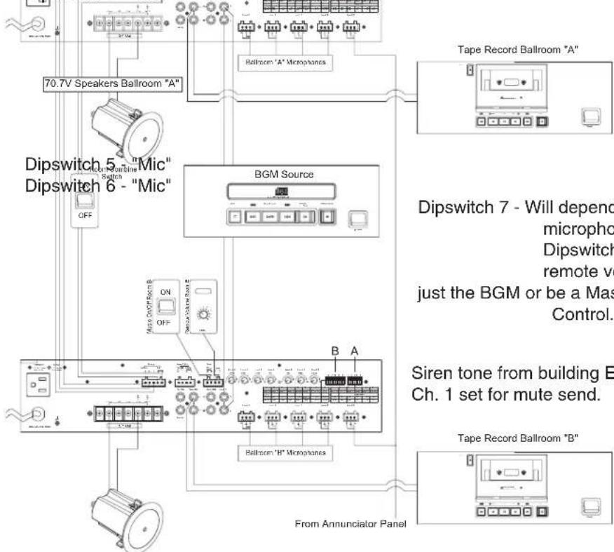
70.7V Speakers Ballroom "B"
Dipswitch 7 - Will depend on type of microphones used Dipswitch 8 - Will depend if the remote volume control will control just the BGM or be a Master Volume Control.
Siren tone from building EVAC system, Ch. 1 set for mute send.
Example 2

Specifications are subject to change without notice
Atlas Sound
AtlasSound.com
1601 JACK MCKAY BOULEVARD ENNIS, TEXAS 75119 U.S.A. • TELEPHONE: (800) 876-3333 • FAX: (800) 765-3435
©2006 ATLAS SOUND LP Printed in U.S.A. 000106 ATS002187 RevA 01/06 PP
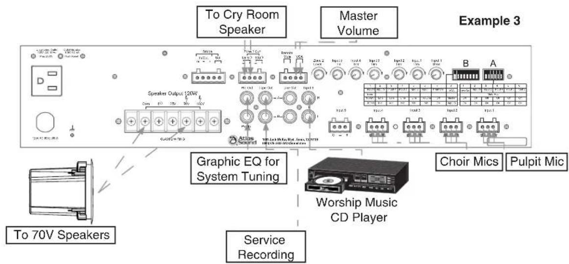
Example 3 - Small House of Worship
The diagram below shows a typical small House of Worship audio system. This system utilizes four microphones, one for the Pulpit and three on the choir. A Master volume control (Atlas AAVC-10K) is connected to the "VCA" terminals for overall level control. For background music, a CD player's audio outputs are connected to Input 6, and a recording device (cassette recorder or computer's audio input) is connected to the Tape Out jacks. For system tuning, a 1/3rd octave graphic EQ is connected to the Pre Out/Pwr In jacks. For the "cry room" an 8Ω speaker is connected to the Zone 2 "1W 8Ω" output.
Dipswitch Settings
Dipswitch "A" 1-6
All Off
Dipswitch "B" 1-8
Switch 1 - 300mV Switch 2 - "Not Used"
Switch 3 - "Mic" Switch 4 - "Mic"
Switch 5 - "Mic" Switch 6 - "Mic"
Switch 7 - Will depend on type of microphones used Switch 8 - Master

Specifications are subject to change without notice
Atlas Sound
AtlasSound.com
1601 JACK MCKAY BOULEVARD ENNIS, TEXAS 75119 U.S.A. • TELEPHONE: (800) 876-3333 • FAX: (800) 765-3435
©2006 ATLAS SOUND LP Printed in U.S.A. 000106 ATS002187 RevA 01/06 PP
WIRING THE AA120/AA240
Speaker Outputs - Use 2 conductor unshielded wire of the appropriate gauge. If you are unsure about this, contact Atlas Sound Tech Support at 1-800-876-3333. Make sure you know how many speakers you need and what tap value you intend to use.
Mic/Line Input - Use 2 conductor w/ shield for low level signals of 20-22 gauge is best. Maintain the proper polarity, + to +, - to -, and shield to ground. For unbalanced signals, connect the (G) to the (—) terminal.
Unbalanced Inputs and Outputs - Pre-made RCA cables can be purchased from vendors to simplify interconnection to external devices.
Zone 2 Out - Use 2 conductor, 20-22 gauge, shielded is best. Terminate the shield at the input to the device if possible.
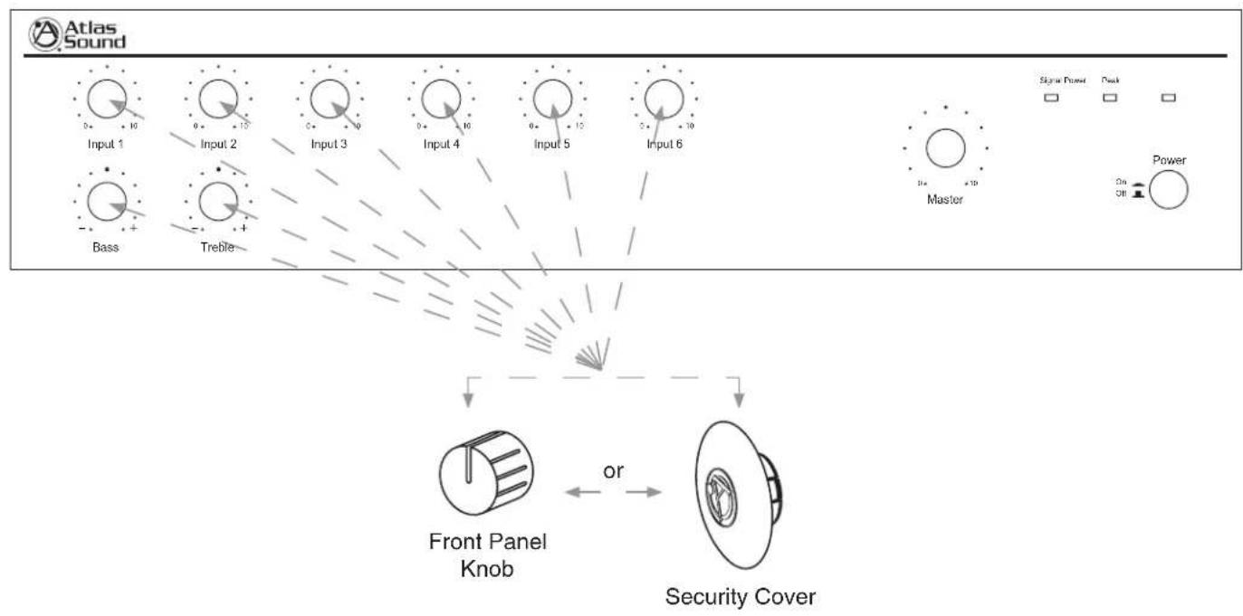
SECURITY COVERS OPTION
In order to prevent unauthorized operation of the AA120/AA240, optional security covers are available which take the place of the front panel knobs. After the AA120/AA240 has been installed and is operating as desired, grasp the front panel knobs and pull straight out from the front panel. Replace the knobs with security covers, Atlas part number AAVCC-5 available in quantities of 5.
flowchart
graph TD
    A["Input 1"] --> B["Bass"]
    C["Input 2"] --> D["Treble"]
    E["Input 3"] --> F["Front Panel Knob"]
    G["Input 4"] --> H["Security Cover"]
    I["Input 5"] --> H
    J["Input 6"] --> H
    K["Master"] --> H
    L["Power"] --> H
    M["Signal Power"] --> N["+/-"]
    O["Peak"] --> P["+/-"]
    Q["On/Off"] --> R["Power"]

Specifications are subject to change without notice
Atlas Sound
AtlasSound.com
1601 JACK MCKAY BOULEVARD ENNIS, TEXAS 75119 U.S.A. • TELEPHONE: (800) 876-3333 • FAX: (800) 765-3435 ©2006 ATLAS SOUND LP Printed in U.S.A. 000106 ATS002187 RevA 01/06 PP
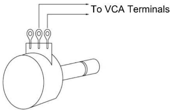
WIRING THE AAVCC-10K VCA POTENTIOMETER -
Atlas part number, AAVCC-10K, consists of a single gang "Decora" style wall plate with a pre-mounted 10K potentiometer and knob.
Use two conductor unshielded wire connecting the pot terminals to the terminals marked "VCA" on the back of the amp.
RACK MOUNT KIT
For permanent mounting of the AA120/AA240 into equipment racks, order part number AARM-2RU. If multiple units are being rack mounted, install Atlas 1RU (SVP19-1-052) vented panels between amplifiers in order to aid cooling.
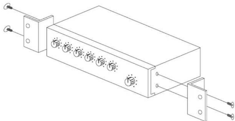
Rack Ear Installation
AA120/AA240 BLOCK DIAGRAM
flowchart
graph TD
    subgraph Channel 1
        A["CHANNEL 1"] --> B["RELIE-MIC"]
        C["CHANNEL 2"] --> D["MIC-MIC"]
        E["CHANNEL 3"] --> F["LIVE-MIC"]
        G["CHANNEL 4"] --> H["LIVE-MIC"]
        I["CHANNEL 5"] --> J["LIVE-MIC"]
        K["CHANNEL 6"] --> L["POWER-AC/OUT"]
    end

    subgraph Channel 2
        B --> M["FUSER"]
        D --> N["FUSER"]
        F --> O["FUSER"]
        H --> P["FUSER"]
        J --> Q["FUSER"]
        L --> R["FUSER"]
    end

    subgraph Channel 3
        M --> S["FUSER"]
        N --> T["FUSER"]
        O --> U["FUSER"]
        P --> V["FUSER"]
        Q --> W["FUSER"]
    end

    subgraph Channel 4
        S --> X["FUSER"]
        T --> Y["FUSER"]
        U --> Z["FUSER"]
        V --> AA["FUSER"]
    end

    subgraph Channel 5
        X --> AB["FUSER"]
        Y --> AC["FUSER"]
        Z --> AD["FUSER"]
    end

    subgraph Channel 6
        AB --> AE["FUSER"]
        AC --> AF["FUSER"]
        AD --> AG["FUSER"]
    end

    subgraph Channel 7
        AE --> AH["FUSER"]
        AF --> AI["FUSER"]
        AG --> AJ["FUSER"]
    end

    subgraph Channel 8
        AH --> AK["FUSER"]
        AI --> AL["FUSER"]
        AJ --> AM["FUSER"]
    end

    subgraph Channel 9
        AK --> AN["FUSER"]
        AL --> AO["FUSER"]
        AM --> AP["FUSER"]
    end

    subgraph Channel 10
        AN --> AQ["FUSER"]
        AO --> AR["FUSER"]
        AP --> AS["FUSER"]
    end

    subgraph Channel 11
        AQ --> AT["POWER-AC/OUT"]
        AR --> AU["POWER-AC/OUT"]
        AS --> AV["POWER-AC/OUT"]
    end

    subgraph Channel 12
        AT --> AW["FUSER"]
        AU --> AX["FUSER"]
        AV --> AY["FUSER"]
    end

    subgraph Channel 13
        AW --> AZ["FUSER"]
        AX --> BA["FUSER"]
        AY --> BB["FUSER"]
    end

    subgraph Channel 14
        AX --> BC["FUSER"]
        AY --> BD["FUSER"]
        AZ --> BE["FUSER"]
        BA --> BF["FUSER"]
    end

    subgraph Channel 15
        AX --> BG["FUSER"]
        AY --> BH["FUSER"]
        AZ --> BI["FUSER"]
        BA --> BJ["FUSER"]
    end

    subgraph Channel 16
        AX --> BK["FUSER"]
        AY --> BL["FUSER"]
        AZ --> BM["FUSER"]
    end

    subgraph Channel 17
        BK --> BN["FUSER"]
        AL --> BO["FUSER"]
        AM --> BP["FUSER"]
    end

    subgraph Channel 18
        B --> B1["INPUT POWER (OPTIONAL)"]
        D --> D1["INPUT POWER (OPTIONAL)"]
        F --> F1["INPUT POWER (OPTIONAL)"]
        H --> H1["INPUT POWER (OPTIONAL)"]
        J --> J1["INPUT POWER (OPTIONAL)"]
        K --> K1["INPUT POWER (OPTIONAL)"]

    subgraph Channel 19
        M --> M1["IN Level"]
        N --> N1["IN Level"]
        O --> O1["IN Level"]
        P --> P1["IN Level"]
        Q --> Q1["IN Level"]

    subgraph Channel 20
        M1 --> M2["PRE-REF."]
        M2 --> M3["BASE TRIGGER"]
        M3 --> M4["SPECTRUCTOR"]
        M4 --> M5["BRIDGE"]
        M5 --> M6["AMOUNTED VOLTAGE"]
        M6 --> M7["KMASTER LEVEL"]

        M7 --> M8["VGA"]
        M8 --> M9["VCA"]

        M9 --> M10["PROCK INPUT EXH"]

        M10 --> M11["LINE OUT B"]

        M11 --> M12["LINE OUT B"]

        M12 --> M13["LINE OUT B"]

        M13 --> M14["LINE OUT B"]

        M14 --> M15["LINE OUT B"]

        M15 --> M16["LINE OUT B"]

        M16 --> M17["LINE OUT B"]

        M17 --> M18["LINE OUT B"]

        M18 --> M19["LINE OUT B"]

        M19 --> M20["LINE OUT B"]

        M20 --> M21["LINE OUT B"]

        M21 --> M22["LINE OUT B"]

        M22 --> M23["LINE OUT B"]

        M23 --> M24["LINE OUT B"]

        M24 --> M25["LINE OUT B"]

        M25 --> M26["LINE OUT B"]

        M26 --> M27["LINE OUT B"]

        M27 --> M28["LINE OUT B"]

        M28 --> M29["LINE OUT B"]

        M29 --> M30["LINE OUT B"]

        M30 --> M31["LINE OUT B"]

        M31 --> M32["LINE OUT B"]

        M32 --> M33["LINE OUT B"]

        M33 --> M34["LINE OUT B"]

        M34 --> M35["LINE OUT B"]

        M35 --> M36["LINE OUT B"]

        M36 --> M37["LINE OUT B"]

        M37 --> M38["LINE OUT B"]

        M38 --> M39["LINE OUT B"]

        M39 --> M40["LINE OUT B"]

        M40 --> M41["LINE OUT B"]

        M41 --> M42["LINE OUT B"]

        M42 --> M43["LINE OUT B"]

        M43 --> M44["LINE OUT B"]

        M44 --> M45["LINE OUT B"]

        M45 --> M46["LINE OUT B"]

        M46 --> M47["LINE OUT B"]

        M47 --> M48["LINE OUT B"]

        M48 --> M49["LINE OUT B"]

        M49 --> M50["LINE OUT B"]

        M50 --> M51["LINE OUT B"]

        M51 --> M52["LINE OUT B"]

        M52 --> M53["LINE OUT B"]

        M53 --> M54["LINE OUT B"]

        M54 --> M55["LINE OUT B"]

        M55 --> M56["LINE OUT B"]

        M56 --> M57["LINE OUT B"]

        M57 --> M58["LINE OUT B"]

        M58 --> M59["LINE OUT B"]

        M59 --> M60["LINE OUT B"]

        M60 --> M61["LINE OUT B"]

        M61 --> M62["LINE OUT B"]

        M62 --> M63["LINE OUT B"]

        M63 --> M64["LINE OUT B"]

        M64 --> M65["LINE OUT B"]

        M65 --> M66["LINE OUT B"]

        M66 --> M67["LINE OUT B"]

        M67 --> M68["LINE OUT B"]

        M68 --> M69["LINE OUT B"]

        M69 --> M70["LINE OUT B"]

        NFE_REF. & NFE_PET. & NFE_OUT.

    subgraph Reference Only
            direction TB
            direction TB
            direction TB
            direction TB
            direction TB
            direction TB
            direction TB
            direction TB
            direction TB
            direction TB
            direction TB
            direction TB
            direction TB
            direction TB
            direction TB
            direction TB
            direction TB
            direction TB
            direction TB
            direction TB
            direction TB
            direction TB
            direction TB
            direction TB
            direction TB
            direction TD
            direction TB
            direction TB
            direction TB
            direction TB
            direction TB
            direction TB
            direction TB
            direction TB
            direction TB
            direction TB
            direction TB
            direction TB
            direction TB
            direction TB
            direction TB
            direction TB
            direction TB
            direction TB
            direction TB
            direction TB
            direction TB
            direction TB
            direction TB
            direction TB
            direction TCN_REF. & NCN_PET.
            direction TCN_REF. & NCN_OUT.
            direction TCN_REF. & NCN_OUT.
            direction TCN_REF. & NCN_OUT.
            direction TCN_REF. & NCN_OUT.
            direction TCN_REF. & NCN_OUT.
            direction TCN_REF. & NCN_OUT.
            direction TCN_REF. & NCN_OUT.
            direction TCN_REF. & NCN_OUT.
            direction TCN_REF. & NCN_OUT.
            direction SCN_REF. & NCN_PET.
            direction SCN_REF. & NCN_PET.
            direction SCN_REF. & NCN_PET.
            direction SCN_REF. & NCN_PET.
            direction SCN_REF. & NCN_PET.
            direction SCN_REF. & NCN_PET.
            direction SCN_REF. & NCN_PET.
            direction SCN_REF. & NCN_PET.
            direction SCN_REF. &
            direction SCN_REF. & NCN_PET.
            direction SCN_REF. & NCN_PET.
            direction SCN_REF. & NCN_PET.
            direction SCN_REF. & NCN_PET.
            direction SCN_REF. & NCN_PET.

    subgraph Reference Only
            direction TCN_REF. & NCN_PET.
            direction TCN_REF. & NCN_PET.
            direction TCN_REF. & NCN_PET.
            direction TCN_REF. & NCN_PET.
            direction TCN_REF. & NCN_PET.
            direction TCN_REF. & NCN_PET.
            direction TCN_REF. & NCN_PET.
            direction TCN_REF. & NCN_PET.

    subgraph Reference Both
            direction TCN_REF. & NCN_PET.
            direction TCN_REF. & NCN_PET.
            direction TCN_REF. & NCN_PET.
            direction TCN_REF. & NCN_PET.
            direction TCN_REF. & NCN_PET.
            direction TCN_REF. & NCN_PET.
            direction TCN_REF. & NCN_PET.

    subgraph Reference Side
            direction TCN_REF. & NCN_PET.
            direction TCN_REF. & NCN_PET.
            direction TCN_REF. & NCN_PET.
            direction TCN_REF. & NCN_PET.
            direction TCN_REF. & NCN_PET.

    subgraph Reference Side Top
            direction TCN_REF. & NCN_PET.
            direction TCN_REF. & NCN_PET.
            direction TCN_REF. & NCN_PET.
            direction TCN_REF. & NCN_PET.

    end

    subgraph Reference Side Bottom
          direction TCN_REF. & NCN_PET.
          direction TCN_REF. & NCN_PET.
          direction TCN_REF. & NCN_PET.

    subgraph Reference Side Top Right Side:
          direction TCN_REF. & NCN_PET.
          direction TCN_REF. & NCN_PET.
          direction TCN_REF. & NCN_PET.

    end

    subgraph Reference Side Bottom Right Side:
          direction TCN_REF. & NCN_PET.
          direction TCN_REF. & NCN_PET.
          direction TCN_REF. & NCN_PET.

    subgraph Reference Side Top Left Side:
          direction TCN_REF. & NCN_PET.
          direction TCN_REF. & NCN_PET.

    end

    subgraph Reference Side Top Right Side:
          direction TCN_REF. & NCN_PET.
          direction TCN_REF. & NCN_PET.

    end

    subgraph Reference Side Bottom Right Side:
          direction TCN_REF. & NCN_PET.
          direction TCN_REF. & NCN_PET.

    end

    subgraph Reference Side Top Right Side:
          direction TCN_REF. & NCN_PET.
          direction TCN_REF. & NCN_PET.

    end

    subgraph Reference Side Bottom Right Side:
          direction TCN_REF. & NCN_PET.
          direction TCN_REF. &NCW_LR

    end
INPUT TRANSFORMER INSTALLATION
Optional Input 1 Transformer Installation
Contact Atlas Sound at 1-800-876-3333 for price and availability.
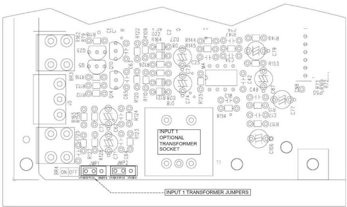
(p/n AAIT-600)
SPECIFICATIONS FOR AA120 and AA240
| POWER OUTPUT | ||||
| Max. Average Power @ 50Hz-20kHz with .5% THD (10-80kHz fi Iter) 8 Ohm, 1kHz, 120W RMS (AA120) 240W RMS (AA240) | ||||
| TRANSFORMER OUTPUTS | ||||
| 25V | AA120 | 120W RMS | AA240 | 240W RMS |
| 70V | AA120 | 120W RMS | AA240 | 240W RMS |
| 100V | AA120 | 120W RMS | AA240 | 240W RMS |
| FREQUENCY RESPONSE | ||||
| 50Hz-20kHz ± 3dB | ||||
| DISTORTION | ||||
| <1% at rated power (1kHz) | ||||
| SENSITIVITY | ||||
| Input 1 | Line/Tel | 316mV (-10dBV) | 10k Ohm (600Ω w optional/transformer) | |
| Mic | .316mV~3.16mV (-50dBV~ -70dBV) | |||
| Inputs 2-5 | Line | 316mV (-10dBV) | 10k Ohm | |
| Mic | .316mV~3.16mV (-50dBV~ -70dBV) | |||
| Input 6 | Line | 300mV/100mV (-10dBV/-20dBV) Selectable | ||
| OUTPUTS | ||||
| Main: | Transformer coupled, balanced, 8Ω, 25V, and 70V | |||
| Zone 2-8Ω | Unbalanced 1W | |||
| Zone 2-600Ω | Balanced 1.5V | |||
| SIGNAL TO NOISE RATIO | ||||
| Mic | >55dB | |||
| Line | >55dB | |||
| Telephone | 75dB | |||
| TONE CONTROLS | ||||
| Bass | ±10dB @ 100Hz | |||
| Treble | ±10dB @ 10kHz | |||
| INDICATORS | ||||
| Power, signal, peak | ||||
| POWER CONSUMPTION | ||||
| AA120 300 Watts | AA240 500 Watts | |||
| DIMENSIONS | ||||
| 16.54"W x 4.219"H x 14.06"D (420mm X 107mm X 357mm) | ||||
| WEIGHT | ||||
| AA120 26.44 lbs (12kg) | AA2400 27.85 lbs (12.63kg) | |||
NOTES:
NOTES:
Limited Warranty
All products manufactured by Atlas Sound are warranted to the original dealer/installer, industrial or commercial purchaser to be free from defects in material and workmanship and to be in compliance with our published specifications, if any. This warranty shall extend from the date of purchase for a period of three years on all Atlas Sound products, including SOUNDOLIER brand, and ATLAS SOUND brand products except as follows: one year on electronics and control systems; one year on replacement parts; and one year on Musician Series stands and related accessories. Additionally, fuses and lamps carry no warranty. Atlas Sound will solely at its discretion, replace at no charge or repair free of charge defective parts or products when the product has been applied and used in accordance with our published operation and installation instructions. We will not be responsible for defects caused by improper storage, misuse (including failure to provide reasonable and necessary maintenance), accident, abnormal atmospheres, water immersion, lightning discharge, or malfunctions when products have been modified or operated in excess of rated power, altered, serviced or installed in other than a workman like manner. The original sales invoice should be retained as evidence of purchase under the terms of this warranty. All warranty returns must comply with our returns policy set forth below. When products returned to Atlas Sound do not qualify for repair or replacement under our warranty, repairs may be performed at prevailing costs for material and labor unless there is included with the returned product(s) a written request for an estimate of repair costs before any nonwarranty work is performed. In the event of replacement or upon completion of repairs, return shipment will be made with the transportation charges collect.
EXCEPT TO THE EXTENT THAT APPLICABLE LAW PREVENTS THE LIMITATION OF CONSEQUENTIAL DAMAGES FOR PERSONAL INJURY, ATLAS SOUND SHALL NOT BE LIABLE IN TORT OR CONTRACT FOR ANY DIRECT, CONSEQUENTIAL OR INCIDENTAL LOSS OR DAMAGE ARISING OUT OF THE INSTALLATION, USE OR INABILITY TO USE THE PRODUCTS. THE ABOVE WARRANTY IS IN LIEU OF ALL OTHER WARRANTIES INCLUDING BUT NOT LIMITED TO WARRANTIES OF MERCHANTABILITY AND FITNESS FOR A PARTICULAR PURPOSE.
Atlas Sound does not assume, or does it authorize any other person to assume or extend on its behalf, any other warranty, obligation, or liability. This warranty gives you specific legal rights and you may have other rights which vary from state to state.
SERVICE
Should your AA Series amplifi er require service, please contact the Atlas Sound warranty department at 1-866-689-8055, ext. 277 to obtain an RA number.
Atlas Sound Tech Support can be reached at 1-800-876-3333.
Visit our website at www.AtlasSound.com to see other Atlas products.

Specifications are subject to change without notice
Atlas Sound
AtlasSound.com
1601 JACK MCKAY BOULEVARD ENNIS, TEXAS 75119 U.S.A. • TELEPHONE: (800) 876-3333 • FAX: (800) 765-3435 ©2006 ATLAS SOUND LP Printed in U.S.A. 000106 ATS002187 RevA 01/06 PP

- TABLE OF CONTENTS
- SAFETY INSTRUCTIONS
- INTRODUCTION
- FEATURES
- APPLICATIONS
- SAFETY PRECAUTIONS
- Message Conventions and Safety Symbols
- WARNING
- CAUTION
- WHEN INSTALLING THE PRODUCT
- WARNING WHEN THE DEVICE IS IN USE
- Atlas Sound
- AtlasSound.com
- CAUTION WHEN INSTALLING THE PRODUCT
- CAUTION WHEN THE PRODUCT IS IN USE
- Power Switch
- Power LED
- Peak LED
- Signal LED
- Master Gain Control
- Input 1-6 Controls
- Bass Control
- Treble Control
- REAR PANEL DESCRIPTION
- Dipswitch "A" Positions 1-6
- Dipswitch "B" Positions 1-8
- Input 1 Sens
- Inputs 1-5 Trim
- Zone 2 Level
- VCA
- Remote Mute
- Zone 2 Output - 600Ω
- Zone 2 Output - 1 Watt 8Ω
- Bridge In/Out
- Bridge Select
- Input 1
- Inputs 2-5
- Input 6
- Line Out A/B
- Note the following conditions for LINE OUT
- Tape Out A/B
- Pre Out
- Pwr In
- Speaker Terminals
- Power Cord
- Unswitched Outlet
- Circuit Breaker – Unswitched Outlet
- QUICK START EXAMPLES
- Example 1 — System Paging, BGM, and MOH with Remote Master Level Control
- Dipswitch Settings
- Example 2 - Hotel Room Combining Using Two AA120s/AA240s
- Dipswitch "B" 1-8
- Example 3 - Small House of Worship
- WIRING THE AA120/AA240
- SECURITY COVERS OPTION
- WIRING THE AAVCC-10K VCA POTENTIOMETER -
- RACK MOUNT KIT
- AA120/AA240 BLOCK DIAGRAM
- INPUT TRANSFORMER INSTALLATION
- Limited Warranty
- SERVICE
Brand : Atlas Sound
Model : AA120
Category : Blender