AP-15T - Loudspeaker Atlas Sound - Free user manual and instructions
Find the device manual for free AP-15T Atlas Sound in PDF.


| Product Type | Commercial Ceiling Speaker |
| Brand | Atlas Sound |
| Model | AP-15T |
| Power Rating | 15W (RMS) at 70V/100V |
| Impedance | 8 ohms (bypass) |
| Transformer Taps | 15W, 7.5W, 3.75W |
| Frequency Response | 70 Hz - 20 kHz |
| Sensitivity | 90 dB (1W/1m) |
| Driver Size | 6.5 inches |
| Mounting Type | Ceiling tile (cut-out) |
| Dimensions (Cut-out) | 9.5 inches diameter |
| Depth | 4.5 inches behind ceiling |
| Weight | 3.0 lbs (1.36 kg) |
| Color | White (paintable) |
| Material | Metal baffle, plastic cone |
| Input Connections | Screw terminals (3-pin) |
| Voltage Rating | 70V/100V line |
| Application | Background music, paging |
| Compliance | UL listed |
| Cleaning | Wipe with dry cloth, no liquids |
| Warranty | Limited lifetime |
Frequently Asked Questions - AP-15T Atlas Sound
User questions about AP-15T Atlas Sound
0 question about this device. Answer the ones you know or ask your own.
Ask a new question about this device
Download the instructions for your Loudspeaker in PDF format for free! Find your manual AP-15T - Atlas Sound and take your electronic device back in hand. On this page are published all the documents necessary for the use of your device. AP-15T by Atlas Sound.
USER MANUAL AP-15T Atlas Sound
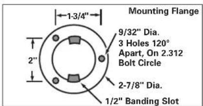
The speaker is provided with a 3-way omni-directional adjustable mounting bracket. The wing nut and the lock pin allow 360^ rotation and 130^ vertical movement. Additional adjustment is provided between the bracket and speaker by means of the 14 " bolt. For ease of installation, the base can be separated from the speaker by removing the 14 " wing nut and locking pin.
CONNECTION
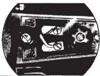
Audio source line-connection is made to the screw terminals. To insure reliability, these special terminals are designed with wire retainers. Phasing is indicated throughout the communications system and attained by maintaining polarity utilizing the numbers "1" & "2" cast into the speaker housing. 1= Common 2= Positive.
IMPEDANCE SWITCH SETTING
The AP-15T, APC-30T, APR-30T and APT-34T (70.7V and 25V line) have a built-in, 7-position switch. The AP-30T (70.7V line) and AP-30T-25 (25V line) have a built-in 6-position switch. Both weather-sealed switches select impedance or wattage taps. The slot in the shaft without the flat indicates the switch setting in use. Desired wattage or impedance can be obtained by referring to the following table.
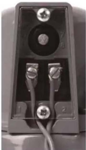
natural_image
Close-up of a black electronic device front panel with two metallic connectors and a circular vent (no visible text or symbols)Speaker Connections and Tap Selector
AP-15T AP-30T AP-30T-25 APC-30T, APR-30T, APT-34T
| Switch Position | 70.7V Watts | 25V Watts | 70.7V Ohms | 25V Watts | 70.7V Ohms | 25V Watts | Ohms | Watts | Watts | Ohms |
| 1 | 0.9 | - | 5000 | 1.2 | 4000 | 1.2 | 500 | 1.8 | - | 2500 |
| 2 | 1.8 | - | 2500 | 2.5 | 2000 | 2.5 | 250 | 3.7 | - | 1300 |
| 3 | 3.8 | 0.48 | 1300 | 5.0 | 1000 | 5.0 | 125 | 7.5 | - | 666 |
| 4 | 7.5 | 0.94 | 666 | 7.5 | 666 | 7.5 | 83 | 15.0 | 1.8 | 333 |
| 5 | 15.0 | 1.8 | 333 | 15.0 | 333 | 15.00 | 42 | 30.0 | 3.7 | 167 |
| 6 | - | 7.5 | 89 | 30.0 | 167 | 30.0 | 21 | - | 7.0 | 89 |
| 7 | - | 15.0 | 45 | - | - | - | - | - | 15.0 | 45 |
ACCESSORIES:
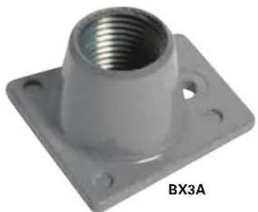
Conduit/cable adapters Model BX-1A for AP-30 Models.
BX-2A for AP-15 Models & BX-3A for APF Models - Specially designed covers for conduit and armored cable connect directly into the speaker. These accessories provide additional protection to the speaker wires, and the cover assures tamper-proof installation and vandalism-protection.
natural_image
Metallic mechanical component with threaded flange and mounting base (no text or symbols visible)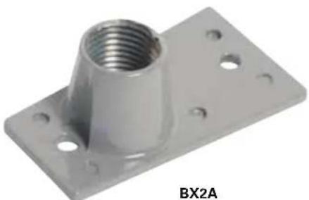
natural_image
Metal mechanical bracket with threaded top and mounting holes (no text or symbols visible)MOUNTING: The speaker is provided with a 3-way omni-directional adjustable mounting bracket. The wing nut and the lock pin allow 360^ rotation and 130^ vertical movement. Additional adjustment is provided between the bracket and speaker by means of the 14 " bolt. For ease of installation, the base can be separated from the speaker by removing the 14 " wing nut and locking pin.
CONNECTION: Audio source line-connection is made to the screw terminals. To insure reliability, these special terminals are designed with wire retainers. Phasing is indicated throughout the communications system and attained by maintaining polarity utilizing the numbers "1" & "2" cast into the speaker housing. (#2 is recommended for positive terminal).
natural_image
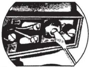
Illustration of a person inserting into a device with a tool (no text or symbols visible)IMPEDANCE SWITCH SETTING: The AP-15T(C), AP-30T(C), APC-30T,
APT-34T, APW-15T and the APW-30Thave a built-in 7-position switch. The AP-30T-25 has a built-in 6-position switch. Both weather-sealed switches select impedance or wattage taps. The slot in the shaft without the flat indicates the switch setting in use. Desired wattage or impedance can be obtained by referring to the following table.
| AP-15T(C), APW-15T | AP-30T(C), APC-30T, APW-30T | |||||||
| Switch Position | 100V Watts | 70V Watts | 25V Watts | Ohms | 100V Watts | 70V Watts | 25V Watts | Ohms |
| 1 | 2.0 | 1.0 | .12 | 5000Ω | 4.0 | 2.0 | .25 | 2500Ω |
| 2 | 4.0 | 2.0 | .25 | 2500Ω | 7.7 | 3.8 | .48 | 1300Ω |
| 3 | 7.7 | 3.8 | .48 | 1300Ω | 15.0 | 7.5 | .9 | 666Ω |
| 4 | 15.0 | 7.5 | .94 | 666Ω | 30.0 | 15.0 | 1.8 | 333Ω |
| 5 | * | 15.0 | 1.8 | 333Ω | * | 30.0 | 3.7 | 167Ω |
| 6 | * | * | 7.5 | 89Ω | * | * | 7.0 | 89Ω |
| 7 | * | * | 15.0 | 45Ω | * | * | 15.0 | 45Ω |
*=Do Not Use This Tap On Respective Volts
| AP-30T-25 | ||
| Switch Position | 25V Watts | Ohms |
| 1 | 1.2 | 500Ω |
| 2 | 2.5 | 250Ω |
| 3 | 5.0 | 125Ω |
| 4 | 7.5 | 83Ω |
| 5 | 15.0 | 42Ω |
| 6 | 30.0 | 21Ω |
CABLE STRAIN RELIEF: A strain relief for SV or zip type cable is obtained by utilizing the recess in the casting and the plastic cover. The wide slot is for SV and the narrow side for zip or 2-conductor cable.
ACCESSORIES:
Conduit/cable adapters Model BX-1A for AP-30 Models. BX-2 for AP-15 Models & BX-3 for APF Models - Specially designed covers for conduit and armored cable connect directly into the speaker. These accessories provide additional protection to the speaker wires, and the cover assures tamper-proof installation and vandalism-protection.
natural_image
Close-up of a vintage mechanical device with visible gears and buttons (no readable text or symbols)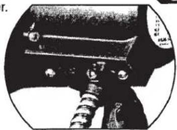
natural_image
Close-up of a mechanical component with threaded shaft and bolts (no visible text or symbols)
Specifications are subject to change without notice
www.AtlasSound.com
1601 JACK MCKAY BOULEVARD ENNIS, TEXAS U.S.A. • TELEPHONE: (800) 876-3332 • FAX: (800) 765-3435 ©2001 ATLAS SOUND LP Printed in U.S.A. JN ATS0000485 PN 373177
AP-15/AP-15T(C)
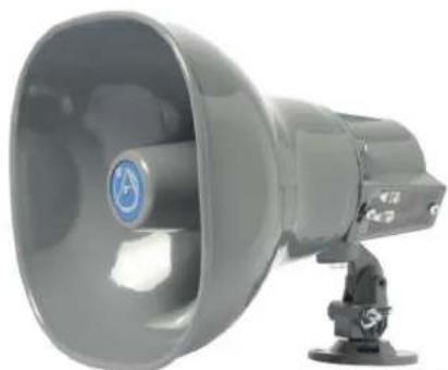
Omni-Purpose® 15 Watt Horn Loudspeakers
natural_image
Gray megaphone with control panel, no visible text or symbolsAP-15 Series
Specifications
Models
AP-15,
AP-15T(C)
Power Rating 15 Watts Continuous
Frequency Response 400 - 14,000 Hz (Nominal) 500 Hz - 6000 Hz (±5dB)
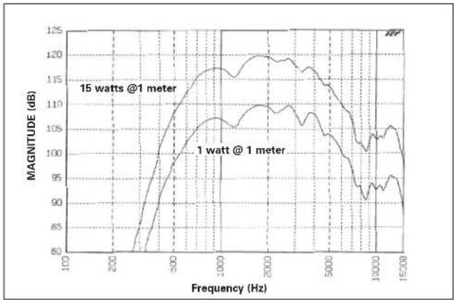
Sensitivity 120dB at 15 Watts (Peak) 116dB at 15 Watts/1 Meter (Avg) 500 - 6000 Hz 106dB at 1 Watt/1 Meter (Avg) 500 - 6000 Hz
Dispersion Angle 70° (-6dB, 2000 Hz Octave Band)
Weight AP-15: 3.5 lbs (1.6kgs) AP-15T: 4 lbs (1.8kgs)
Finish Baked Epoxy
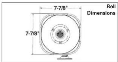
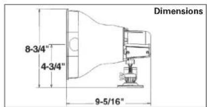
Dimensions H8
314^× W718^× D9516^*
Temperature Range -40°C - 70°C
Architect and Engineer Specifications
Loudspeakers shall be Atlas Sound Model ____ (AP-15, AP-15C, AP-15T, AP-15TC) or approved equal. Each loudspeaker unit shall be supplied with integral compression driver and shall be constructed of structural aluminum and ABS plastic with double re-entrant acoustic path and exponentially-flared square bell. The weather-resistant unit shall have a continuous audio power rating of 15 watts. Frequency response range shall be 400-14,000 Hz (Nominal), 500-6000 Hz (+5dB). Sound pressure level shall be 116dB (15W/1M), 106dB (1W/1M). Sound dispersion shall be 70 degrees (-6dB, 2000 Hz octave band). Mounting bracket shall allow vertical and horizontal adjustment and include provisions for surface mounting, banding or strapping. Loudspeaker shall have impedance selection, via seven-position switch of 5000, 2500, 1300, 666, 333, 89 and 45 ohms. Power taps shall be available at .48, .94, 1.8, 7.5, and 15 watts for 25V line, 1, 2, 3.8, 7.5, and 15 watts for 70.7V line and 2, 4, 8 and 15 watts for 100V line. Wiring terminals shall be enclosed for security and weather protection. Finish shall be grey or beige (C) baked epoxy as indicated. Dimensions shall be H 834 " x W 712 " x D 9116 ".
Features
• Superior Intelligibility for Voice and Tone Signaling
• High-Efficiency Driver with Proven Performance Reliability
- Transformer (T) Equipped Version for Versatile 25, 70.7, or 100V Line Applications
- Omni-Purpose® Bracket for Precise Positioning
• Environment Resistant for Outdoor and Indoor Use
• U.S. Trademark Design is World Recognized for Quality and Dependability
• Available in Grey or Beige (C) Finish
Applications
AP-15 and AP-15T environment-resistant loudspeakers are the world standard for high-intelligibility voice and signal transmission in medium-power indoor and outdoor public address, intercom, security and industrial-signal-system applications. Cost effective, 15-watt units incorporate high-efficiency compression drivers to project sound over long distances or wide areas with fewer loudspeakers. The AP-15 Series is recognized throughout the world as "the performance standard" for commercial sound, intercom and protective-signaling systems. Units are commonly installed in commercial buildings, distribution centers, factories, schools, public access areas, civic centers and recreational facilities.
Description
The 8 Ohm Model AP-15 and the transformer-equipped Model AP-15T are double re-entrant loudspeakers which deliver 15 Watts of continuous power handling, superior intelligibility and unparalleled efficiency. The AP-15 Series operates within a nominal frequency response range of 400-14,000 Hz and offers a sensitivity of 120dB at rated power to provide clear voice and signal communication.
Transformer-equipped Model AP-15T includes a versatile, 3-way, 25, 70.7, 100V line transformer to meet a variety of distributed system needs. The transformer is adjustable using Atlas Sound's exclusive Vari-Tap® Connect Center which features a 7-position, watts/impedance selection switch. The labor-saving Vari-Tap® switch is screwdriver adjustable and includes a protective cover with built-in cable strain relief.
The trademarked squared-bell design signifies Atlas Sound quality and reliability. The Omni-Purpose® mounting bracket (supplied on all models) achieves precise positioning in the vertical and horizontal planes with a single adjustment and includes provisions for loudspeaker installation on conventional surfaces as well as for strap-mounting on I-beams or pillars. AP Series loudspeakers are U.S. made to assure superior service reliability. Weather-resistant construction is metal and matching ABS plastic with metal components finished in grey epoxy (standard) or beige epoxy (Model AP-15TC).
The AP-15 Series also includes a 45-ohm Model AP-15-45 and a 4 ohm Model AP-15-4 which are designed respectively for intercom and CB/auxiliary radio applications. (See SL2-1567).
Accessories
BX-2A
Vandal resistant cover plate for armored cable
and conduit connection. Constructed of cast aluminum.

Atlas Sound
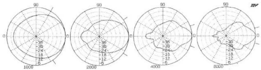
| Frequency (Hz) | QNDi | Beamwidth | (Degrees) |
| 1000 5.15 | 7.12 115 | ||
| 2000 13.90 | 11.43 70 | ||
| 4000 32.20 | 15.08 40 | ||
| 8000 39.90 | 16.01 30 |
Polars Are Normalized To Zero On Axis
line
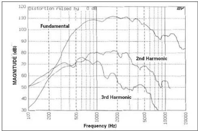
| Frequency (Hz) | Fundamental | 2nd Harmonic | 3rd Harmonic | | -------------- | ----------- | ------------ | ------------ | | 100 | 50 | 50 | 50 | | 200 | 60 | 60 | 60 | | 500 | 100 | 70 | 70 | | 1000 | 110 | 80 | 80 | | 2000 | 110 | 80 | 80 | | 5000 | 100 | 70 | 70 | | 10000 | 90 | 50 | 50 | | 20000 | 80 | 40 | 40 |AP-15(T) (Harmonic Distortion - 1.5 watts @ 1 meter)
DRIVER PROTECTION: The horn loudspeaker should not be operated at frequencies outside the specified range, especially below horn cut-off. It is suggested that any program material be high-passed at 300 Hz with a 6dB per octave filter. This can be done by a low level filter at the amplifier input or by a series capacitor at each loudspeaker. Electrolytic capacitors can be used but they must be non-polarized (See Typical Capacitor Values Chart).
| Typical Capacitor Values | |||
| 8 Ohm Driver 25 Volt Line 70 Volt Line 100 Volt Line | |||
| 70 mfd 15 mfd 2 mfd 1 mfd | |||
| AP-15T Vari-Tap® Control Connect Center Xfmr. Power Taps | ||||
| Switch Position | Impedance (Ohms) | Watts @ 25V | Watts @ 70.7V | Watts @ 100V |
| 1 | 5000 | - | 1 | 2 |
| 2 | 2500 | - | 2 | 4 |
| 3 | 1300 | .48 | 3.8 | 8 |
| 4 | 666 | .94 | 7.5 | 15 |
| 5 | 333 | 1.8 | 15 | X* |
| 6 | 89 | 7.5 | X* | X* |
| 7 | 45 | 15 | X* | X* |
* Do Not Use
line
| Frequency (Hz) | 15 watts @ 1 meter (dB) | 1 watt @ 1 meter (dB) | | -------------- | ------------------------ | ---------------------- | | 100 | 80 | 80 | | 200 | 90 | 90 | | 500 | 110 | 105 | | 1000 | 120 | 110 | | 2000 | 120 | 110 | | 5000 | 115 | 105 | | 10000 | 105 | 95 | | 15000 | 95 | 90 |AP-15(T) Frequency Response
line
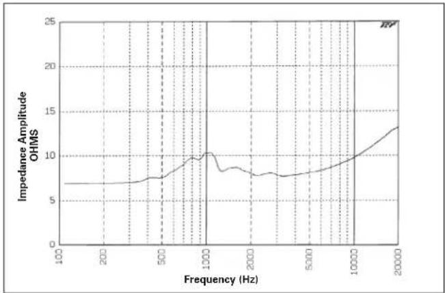
| Frequency (Hz) | Impedance Amplitude OHMS | | -------------- | ------------------------ | | 100 | 7.0 | | 200 | 7.0 | | 500 | 7.5 | | 1000 | 10.0 | | 2000 | 8.0 | | 5000 | 8.5 | | 10000 | 10.0 | | 20000 | 13.0 |AP-15 (Impedance Sweep)
Atlas Sound products are designed and tested in our well-equipped research laboratory which contains a fully anechoic chamber, complete analog Bruel & Kjaer measurement equipment and Techron ^® TEF 20 ^® audio analyzer. Atlas Sound is proud to be a beta site for TEF software.
Brand : Atlas Sound
Model : AP-15T
Category : Loudspeaker