
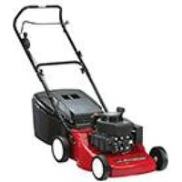
SP534ES - Lawn mower MOUNTFIELD - Free user manual and instructions
Find the device manual for free SP534ES MOUNTFIELD in PDF.


| Product Type | Lawn mower |
| Brand | Mountfield |
| Model | SP534ES |
| Type | ESL 534 TR/E |
| Cutting Width | 51 cm |
| Cutting Height Adjustment | Lever-operated, 4 wheels must be set to same height |
| Engine Type | 4-stroke, single-cylinder, gasoline |
| Engine Displacement | Approx. 140 cc (typical for 51 cm) |
| Fuel | Unleaded gasoline, min. 90 octane |
| Fuel Tank Capacity | 1.2 L |
| Engine Oil Capacity | 0.65 L |
| Oil Viscosity | SAE 30 (5–35 °C), 5W‑30 or 10W‑30 (‑15 to +5 °C) |
| Spark Plug | PN2VC (Champion) or equivalent RN9YC |
| Spark Plug Gap | 0.6–0.8 mm |
| Starting System | Recoil start; electric start (key) on some variants |
| Battery (if electric) | FIAMM FG 20451, 12 V, 4.5 Ah, VRLA |
| Drive System | Rear‑wheel drive, engagement lever |
| Blade Brake | Yes, lever‑operated |
| Grass Catcher | Rigid plastic or cloth, capacity approx. 50 L |
| Handle Height Adjustment | Two positions (loosen knobs) |
| Sound Power Level (measured) | 97 dB(A) |
| Guaranteed Sound Power Level | 98 dB(A) |
| Vibration Level (handle) | 16 m/s² |
| Weight | Approx. 32 kg |
| Safety Features | Blade brake, stone‑guard, grass‑catcher interlock, engine stop on lever release |
| Maintenance Interval – Oil Change | First 5 hours, then every 50 hours or every season |
| Maintenance Interval – Air Filter | Every 25 hours; clean and oil foam |
Frequently Asked Questions - SP534ES MOUNTFIELD
User questions about SP534ES MOUNTFIELD
0 question about this device. Answer the ones you know or ask your own.
Ask a new question about this device
Download the instructions for your Lawn mower in PDF format for free! Find your manual SP534ES - MOUNTFIELD and take your electronic device back in hand. On this page are published all the documents necessary for the use of your device. SP534ES by MOUNTFIELD.
USER MANUAL SP534ES MOUNTFIELD
IMPORTANT: Before starting the motor for the first time, carefully read the instructions as set out in the engine handbook.
CAUTION! Check oil level before starting.
natural_image
Simple line drawing of a fuel pump (no text or symbols)Type ES 414
ES/ESL 464
ES/ESL 464 TR
ES/ESL 464 TR-E
ES/ESL 534
ES/ESL 534 TR
ES/ESL 534 TR-E

FR TONDEUSE - MANUEL D'UTILISATION
Read this manual carefully before using the machine.
For instructions regarding the engine and the battery (if supplied), read the relevant manuals.
1. FINISH ASSEMBLY
NOTE - The machine can be supplied with some of the components already fitted.
1.1a "A" type handle - without height adjustment - Attach the bottom of the handle (1) to the holes on the side of the chassis. Secure it using the nuts and bolts supplied (2). Fit the top of the handle (3) using the nuts and bolts (4) provided, ensuring that the spiral (5) of the starter cable is positioned correctly.
On some models: connect the engine brake cable (6) by attaching the wire terminal (7) to the hole on the control lever (8). Fasten the cable support (6a) to the handle using the nuts and bolts (9) as shown.
Attach the control cables using the clamps (10).
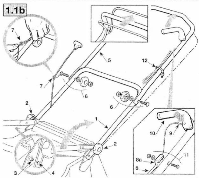
1.1b "B" type handle - with height adjustment -
Return the bottom of the fitted handle (1) to its working position and lock it in place using the bottom knobs (2). Make sure that the two pins (3) stay inside their holes (4).
Fit the top of the handle (5) using the nuts and bolts (6) provided, ensuring that the spiral (7) of the starter cable is positioned correctly.
On some models: connect the engine brake cable (8) by attaching the wire terminal (9) to the hole on the control lever (10). Fasten the cable support (8a) to the handle using the nuts and bolts (11) as shown.
Attach the control cables using the clamps (12).
By loosening the knobs (2) the handle can be set at two different heights.
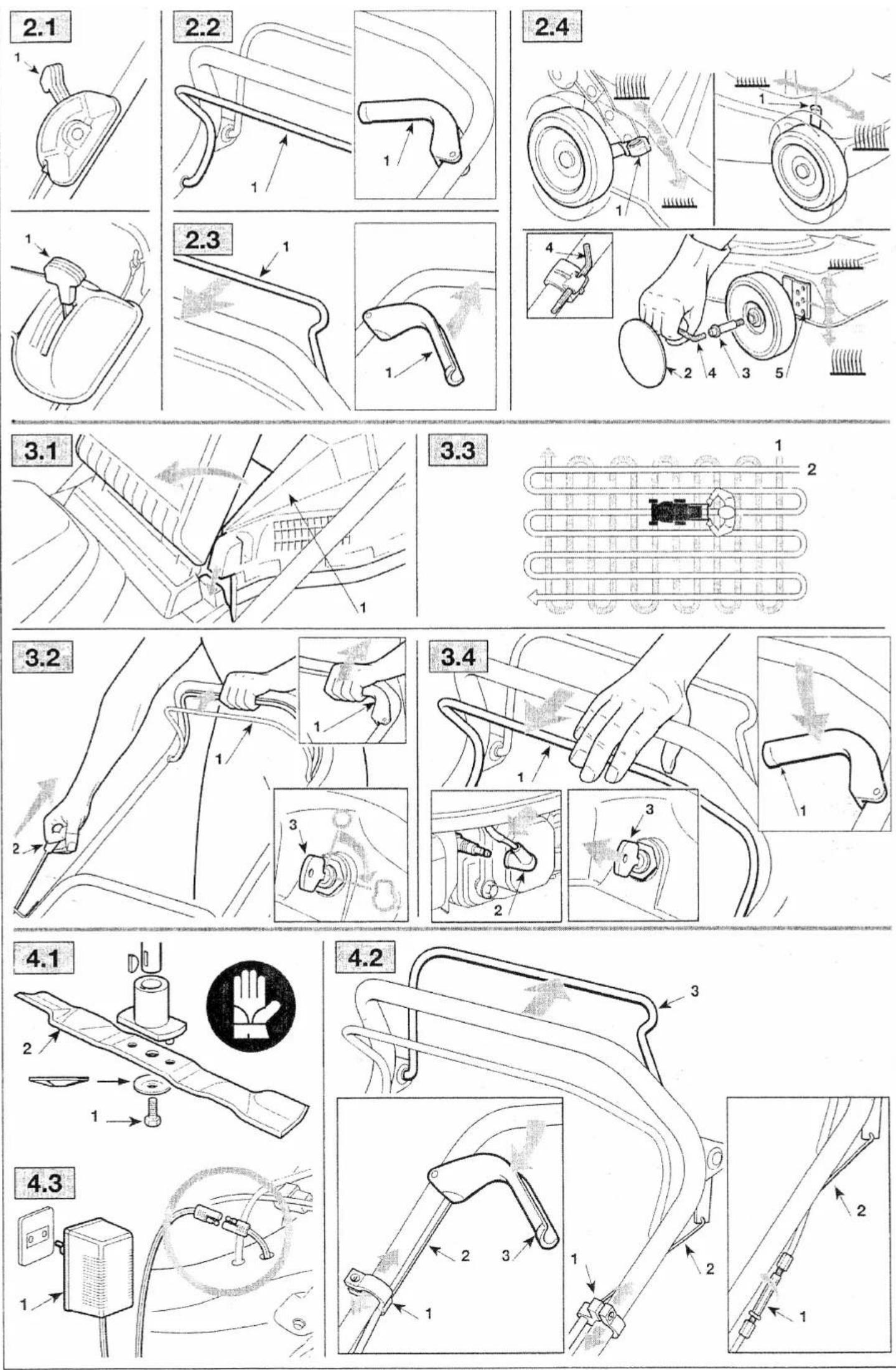
1.2 Assemble the dashboard (1) following the steps shown.
1.3a For a rigid grass-catcher:
Carefully detach the plate (1) and washers (2) from the top of the grass-catcher (3). Eliminate the washers (2) and fit the plate (1) onto the top of the grass-catcher (3) so that it clicks into place. Assemble the two parts of the grass-catcher (3) and (4), making sure that the hooks are fully locked into place and fasten them using the screws supplied (5).
1.3b For a plastic and cloth grass-catcher:
Carefully detach the plate (11) and washers (12) from the top of the grass-catcher (13). Fit the plate (11) onto the top of the grass-catcher (13) so that it clicks into place. With the plastic part (13) upside-down, fasten the frame (15) using the screws (16) and washers (12). Insert the frame (15) in the grass-catcher (17) and attach the plastic bars (18) using a screwdriver, as shown in the drawing. Fit the edge of the cloth (19) right into the groove of the plastic part (13), starting 5-7 mm from the ends.
1.4 On models with an electric starter, connect the battery cable to the lawnmower's general cable connection.
2. DESCRIPTION OF CONTROLS
2.1 The throttle (where fitted) is controlled by the lever (1) and positioned as shown on the relative plate. Some models have a fixed speed, and therefore no need of a throttle.
2.2 The blade brake is controlled by the lever (1), which should be held against the handle when starting and using the lawnmower. The engine stops when the lever is released.
2.3 In the power-driven models, pull the lever (1) towards the handle for forward movement. The lawn-mower stops moving forward when the lever is released.
2.4 The cutting height is adjusted using the levers (1).
On some models, remove the brake cover (2) and unscrew the pin (3) using the wrench (4) provided; fit the wheels into the required hole (5) and fully tighten the pin (3) using the wrench (4). The four wheels must be at the same height. MAKE THIS ADJUSTMENT ONLY WHEN THE BLADE IS STOPPED.
3. GRASS CUTTING
3.1 Lift the stone-guard and attach the grass-catcher (1) correctly as shown in the drawing.
3.2 To start the engine, follow the instructions in the engine booklet and then pull the blade brake lever (1) towards the handle and give a sharp pull on the starter cable knob (2). For models with an electric starter, turn the starter key (3).
3.3 The lawn will look better if it is always cut to the same height and in alternate directions.
3.4 When you have finishing mowing, release the brake lever (1) and disconnect the spark plug cap (2). Remove the starter key (3) (where fitted). WAIT FOR THE BLADE TO STOP before carrying out any type of work on the machine.
4. ROUTINE MAINTENANCE
IMPORTANT - Regular, careful maintenance is essential for keeping the safety level and original performance of the machine unchanged in time.
Store the lawnmower in a dry place.
1) Wear strong working gloves during any cleaning, maintenance or adjustment operation on the machine.
2) Carefully clean the machines with water after each cut; remove the grass debris and mud accumulated inside the chassis to avoid their drying and thus making the next start-up difficult.
3) The paintwork on the inside of the chassis may peel off in time due to the abrasive action of the cut grass; in this case, intervene promptly by touching up the paintwork using a rustproof paint to prevent the formation of rust that would lead to corrosion of the metal.
4) Should it be necessary to access the lower part, only tilt the machine from the side shown in the engine handbook; following the relative instructions.
5) Do not drip petrol onto the plastic parts of the motor or the machine to prevent damaging them and remove all traces of spilt petrol immediately. The warranty does not cover damage to plastic parts caused by petrol.
4.1 All operations on the blade should be carried out at a specialized centre.
Note for specialized centres: Reassemble the blade (2) as shown in the drawing and tighten the central screw (1) using a torque wrench set to 50-60 Nm.
4.2 In the power-driven models, regulate the adjuster (1) so that the wire (2) is slightly loose, with the lever (3) at rest
4.3 To recharge a flat battery, connect to the battery charger (1) following the instructions in the battery maintenance handbook.
Do not connect the battery charger directly to the engine terminal. It is not possible to start the engine using the battery charger as a power source, as it may get damaged.
If the machine is to remain inactive for a long period, disconnect the battery leads after making sure that the battery is fully charged.
Should you have any doubts or problems, do not hesitate to contact your nearest Service Centre or your Dealer.


natural_image
Technical line drawing of a mechanical component with no visible text or symbols

natural_image
Line drawing of a hand holding a car wheel, with no visible text or symbols

EN SAFETY REGULATIONS TO BE FOLLOWED CAREFULLY
A) TRAINING
1) Read the instructions carefully. Get familiar with the controls and proper use of the equipment. Learn how to stop the engine quickly.
2) Only use the lawnmower for the purpose for which it was designed, i.e. for cutting and collecting grass. Any other use can be hazardous, causing damage to the machine.
3) Never allow children or people unfamiliar with these instructions to use the lawnmower. Local regulations may restrict the age of the operator.
4) Never use the lawnmower:
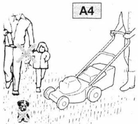
- When people, especially children, or pets are nearby.
- If the operator has taken medicine or substances that can affect his ability to react and concentrate.
5) Remember that the operator or user is responsible for accidents or hazards occurring to other people or their property.
B) PREPARATION
1) While mowing, always wear sturdy footwear and long trousers. Do not operate the equipment when barefoot or wearing open sandals.
2) Thoroughly inspect the area where the equipment is to be used and remove all objects which may be thrown by the machine or damage the cutter assembly and the engine (stones, sticks, metal wire, bones, etc.)
3) WARNING: DANGER! Engine fuel is highly flammable:
- Store fuel in containers specifically designed for this purpose.
- Refuel using a funnel and outdoors only. Do not smoke while refuelling or whenever handling the fuel.
- Add fuel before starting the engine. Never remove the cap of the fuel tank or add fuel while the engine is running or when the engine is hot.
- If fuel is spilled, do not attempt to start the engine but move the machine away from the area of spillage and avoid creating any source of ignition until the fuel has evaporated and the vapour dispersed.
- Replace all fuel tanks and containers caps securely.
4) Substitute faulty silencers.
5) Before use, always inspect the machine, especially the condition of the blades, and check that the screws and cutting assembly are not worn or damaged. Replace worn or damaged blades and screws in sets to preserve balance.
6) Before mowing, attach the discharge opening guards (grass-catcher or stone-guard).
C) OPERATION
1) Do not operate the engine in a confined space where dangerous carbon monoxide fumes can collect.
2) Mow only in daylight or good artificial light.
3) If possible, avoid operating the equipment in wet grass.
4) Always be sure of your footing on slopes.
5) Walk, never run and do not allow yourself to be pulled along by the lawnmower.
6) Mow across the face of slopes, never up and down.
7) Exercise extreme caution when changing direction on slopes.
8) Do not mow on slopes of more than 20°.
9) Exercise extreme caution when pulling the lawnmower towards you.
10) Stop the blade if the lawnmower has to be tilted for transportation when crossing surfaces other than grass, and when transporting the lawnmower to and from the area to be mowed.
11) Never operate the lawnmower with defective guards, or without
safety devices, such as the stone-guard and/or grass-catcher, in place.
12) Do not change the engine governor settings or overspeed the engine.
13) On power-driven models, disengage the drive clutch before starting the engine.
14) Start the engine carefully, following the instructions and keeping feet well away from the blade.
15) Do not tilt the lawnmower when starting the engine. Start the engine on a flat surface that is free of obstacles and tall grass.
16) Do not put hands or feet near or under rotating parts. Keep clear of the discharge opening at all times.
17) Never pick up or carry a lawnmower while the engine is running.
18) Stop the engine and disconnect the spark plug wire:
- Before carrying out any work underneath the cutting deck or before unclogging the chute;
- Before checking, cleaning or working on lawnmower;
- After striking a foreign object. Inspect the lawnmower for damage and make repairs before restarting and operating the lawnmower;
- If the lawnmower starts to vibrate abnormally (find and remove the cause of the vibration immediately).
19) Stop the engine:
- Whenever you leave the lawnmower unattended. Remove the key from models with electric starters.
- Before refuelling.
- Every time you remove or replace the grass-catcher.
- Before adjusting the grass cutting height.
20) Reduce the throttle before turning off the engine and turn the fuel off when you have finished mowing, following the instructions in the engine handbook.
21) When mowing, always keep to a safe distance from the rotating blade. This distance is the length of the handle.
1) Keep all nuts, bolts and screws tight to be sure the equipment is in safe working condition. Regular maintenance is essential for safety and performance.
2) Never store the equipment with fuel in the tank inside a building where vapour may reach a flame or a spark or a source of extreme heat.
3) Allow the engine to cool before storing in an enclosed space.
4) To reduce the fire hazard, keep the engine, exhaust silencer, battery compartment and fuel storage area free of grass, leaves, or excessive grease. Do not leave containers with grass cuttings in rooms.
5) Check the stone-guard and grass-catcher frequently for wear and deterioration.
6) If the fuel tank has to be drained, this should be done outdoors and when the engine is cool.
7) Wear strong work gloves when removing and reassembling the blade.
8) Keep the blade balanced during sharpening. All operations on the blade (dismantling, sharpening, balancing, remounting and/or replacing) require a certain familiarity and special tools. For safety reasons, these jobs are best carried out at a specialized centre.
9) For reasons of safety, do not use the equipment with worn or damaged parts. Parts are to be replaced and not repaired. Use genuine spare parts (blades should always bear the symbol ▲
). Parts that are not of the same quality can damage the equipment and be dangerous for your safety.
E) TRANSPORTATION AND HANDLING
1) Whenever the machine is to be handled, raised, transported or tilted you must:
- wear strong working gloves;
- grasp the machine at the points that offer a safe grip, taking account of the weight and its distribution.
- use an appropriate number of people for the weight of the machine and the characteristics of the vehicle or the place where it has to be placed or collected.

natural_image
Illustration of a lawn mower with a child, adult, and dog nearby (no text or symbols)
natural_image
Illustration of a person using a lawn mower to clean debris near a tree (no text or symbols)


natural_image
Technical illustration of a mechanical device with a labeled section C18, showing internal components and assembly (no text or symbols beyond label)
natural_image
Line drawing of a hand using a tool to cut or inspect the interior of a vehicle (no text or symbols present)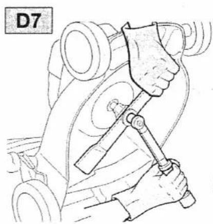
natural_image
Line drawing of a hand using a tool to adjust or install a vehicle component (no text or symbols)

ETIQUETTE D'IDENTIFICATION ET COMPOSANTS DE LA MACHINE IDENTIFICATION LABEL AND MACHINE COMPONENTS KENNUNGSSCHILD UND MASCHINENBAUTEILE ETICHETTA DI IDENTIFICAZIONE E COMPONENTI DELLA MACCHINA IDENTIFICATIELABEL EN ONDERDELEN VAN DE MACHINE

- Niveau de puissance acoustique selon la directive 2000/14/CE
- Marquage de conformité, selon la directive 98/37/CEE
- Année de fabrication
- Type de tondeuse
- Numéro de série
-
Nom et adresse du Constructeur
-
Carter de coupe
- Moteur
- Lame de coupe
- Pare-pierres (déflecteur)
- Sac de ramassage d'herbe
- Guidon
- Levier d'accélérateur
- Levier de frein de lame
-
Levier d'embrayage d'avancement
-
Acoustic power level according to EEC directive 2000/14/CE
-
Mark of conformity according to EEC directive 98/37
- Year of manufacture
- Lawnmower type
- Serial number
-
Name and address of Manufacturer
-
Chassis
- Engine
- Blade
- Stone-guard
- Grass-catcher
- Handle
- Throttle control
- Engine brake lever
-
Drive engagement lever
-
Schalleistungspegel gemäß Richtlinie 2000/14/CE
- Konformitätszeichen gemäß Richtlinie 98/37/EWG
- Herstellungsjahr
- Typ des Rasenmähers
- Kennummer
-
Name und Anschrift des Herstellers
-
Fahrgestell
- Motor
- Schneidwerkzeug (Messer)
- Prallblech
- Grasfangeinrichtung
- Griff
- Gashebel
- Hebel der Motorbremse
-
Kupplungshebel
-
Livello potenza acustica secondo la direttiva 2000/14/CE
- Marchio di conformità secondo la direttiva 98/37/CEE
- Anno di fabbricazione
- Tipo di rasaerba
- Numero di matricola
-
Nome e indirizzo del Costruttore
-
Chassis
- Motore
- Coltello (Lama)
- Parasassi
- Sacco di raccolta
- Manico
- Comando acceleratore
- Leva freno motore
-
Leva innesto trazione
-
Niveau van de geluidssterke volgens de richtlijn 2000/14/CE
- EG-merkteken volgens richtlijn 98/37/EG
- Productiejaar
- Type grasmaaier
- Serienummer
-
Naam en adres van de Fabrikantt
-
Chassis
- Motor
- Mes (maaiblad)
- Deflector
- Opvangzak
- Handgreep
- Versnellingshendel
- Bedieningshendel rem
- Bedieningshendel tractie
DESCRIPTIONS DES SYMBOLES QUI APPARAISSENT SUR LES COMMANDES (là où ils sont prévus) DESCRIPTION OF THE SYMBOLS SHOWN ON THE CONTROLS (where present) BESCHREIBUNG DER SYMBOLE AN DEN STEUERHEBELN (wo vorgesehen) DESCRIZIONE DEI SIMBOLI RIPORTATI SUI COMANDI (dove previsti) BESCHRIJVING VAN DE SYMBOLEN AANGEGEVEN OP DE BEDIENINGEN (indien voorzien)
| 21 | 22 | 23 | 24 | 25 | 26 | 27 | 128 | 229 | 330 |
- Lent
- Rapide
- Starter
- Arrêt du moteur
- Traction insérée
- Arrêt
- Démarrage
-
- vitesse
-
- vitesse
-
- vitesse
-
Slow
- Fast
- Choke
- Engine stop
- Transmission engaged
- Off
- Start
-
- speed
-
- speed
-
- speed
-
Langsam
- Schnell
- Starter
- Motor Stillstand
- Eingeschalteter Antrieb
- Stop
- Starten
-
- Geschwindigkeit
-
- Geschwindigkeit
-
- Geschwindigkeit
-
Lento
- Veloce
- Starter
- Arresto motore
- Trazione inserita
- Arresto
- Avviamento
-
- velocità
-
- velocità
-
- velocità
-
Langzaam
- Snel
- Choke
- Motor stoppen
- Aandrijving ingeschakeld
- Stilstand
- Start
-
- snelheid
-
- snelheid
-
- snelheid
SAFETY REQUIREMENTS - Your lawnmower should be used with due care and attention. Symbols have therefore been placed on various parts of the machine to remind you of the main precautions to be taken. Their full meanings are explained later on. You are also asked to carefully read the safety regulations in the applicable chapter of this handbook.
Should an operation fault occur, have the vehicle's electric system checked and the battery charged if it is flat. Any battery which is defective after being charged shall be covered by the warranty terms and conditions applied by the sale network. In any case, the warranty shall not apply where the defect is caused by improper maintenance or tampering.
SAFETY STANDARDS

It should be borne in mind that the electrolyte is a solution which is diluted in sulphuric acid. In case of contact with your skin, wash thoroughly with water.

If contact is made with your eyes, after washing them thoroughly with water, seek medical advice.

All batteries, while being charged, develop flammable gases that, if triggered, could cause the battery to explode. During charging operations avoid any sparks, live flames and lit cigarettes.

Installed battery: avoid any sparks during installation, removal, checking or start-up operations with jump leads or with auxiliary batteries or equipment; keep away from live flames and cigarettes. Bench charged battery: make sure you correctly connect the battery to the charger (+ with +, - with -). Charge in a ventilated area free from strong draughts avoiding any sparks, live flames or lit cigarettes in the proximity of the battery. Do not place any metal tools on the battery.

Keep out of the reach of children.
USER INSTRUCTIONS AND RECHARGING METHODS
The FIAMM type FG 20451 battery is a sealed battery with a rated 12V voltage controlled by valves.
This is a completely maintenance-free battery and does not require any checking of the electrolyte level or any topping up.
Use:
• Never remove the strip on the top of the cover.
- If there are breakages of the block, cover, or terminals or if the valve housing strip has been tampered with, REPLACE THE BATTERY.
• Always recharge the battery prior to its first use.
• If the vehicle is idle for over a month, remove the battery and store it in a cool and dry place.
• Recharge the battery completely before reinstalling it.
Recharging methods:
- Recharge the battery, with an open circuit voltage lower than 12.60V. If a battery is left discharged for over a month, it may suffer damage.
- To check the charge status, measure the voltage using a voltmeter. The battery (after it has been recharged) must be resting for at least 12 hours.
- Recharge only with a constant voltage battery charger. If a conventional battery charger (for motorcars) is used, the battery may suffer damage.
To recharge the battery, follow the instructions below.
Before the FIRST USE:
| Slow charge | Fast charge | |
| Constant voltage | 14.40÷14.70 V | 14.40÷14.70 V |
| Max. initial current | 1.0 A | 2.0÷4.0 A |
| Charge life | 12÷24 h | 6÷8 h |
Use fast charging only in emergencies.
To PRESERVE charge, regularly use the type CB03 battery charger supplied with.
Charging in conditions of DEEP DISCHARGE:
In the case of batteries that have been kept discharged for prolonged periods of time (more than 15 days) it is recommended that the batteries be charged for at least 48 + 72 hours by means of a type CB03 battery charger at constant current.
Mountfield RM65/ES
SV200 SV200ES R200 R200ES
natural_image
Line drawing of a computer monitor with a keyboard and mouse (no text or symbols)FR MANUEL D'UTILISATION
EN OPERATOR'S MANUAL
DE GEBRAUCHSANWEISUNG
IT MANUALE DI ISTRUZIONI
NL GEBRUIKERSHANDLEIDING
ES MANUAL DE INSTRUCCIONES
PT MANUAL DE INSTRUÇÕES
EL EΓXEIPIΔIO OΔΗΓΙΩΝ
TR KULLANIM KILAVUZU
MK УПАТСТВА ЗА УПОТРЕБА
NO INSTRUKSJONSBOK
SV BRUKSANVISNING
DA BRUGSANVISNING
FI KÄYTTÖOHJEET
CS NÁVOD K POUŽITÍ
PL INSTRUKCJE OBSŁUGI
HU HASZNÁLATI UTASÍTÁS
RU РУКОВОДСТВО ПО ЭКСПЛУАТАЦИИ
HR PRIRUČNIK ZA UPORABO
SL PRIROČNIK ZA UPORABU

| DÉCLARATION DE CONFORMITÉ • EC DECLARATION OF CONFORMITY • EG-KONFORMITÄTSERKLÄRUNG • DICHIARAZIONE DI CONFORMITÄ CEE • EEG VERKLARING VAN OVEREENSTEMMING •DECLARACIÓN “CE” DE CONFORMIDAD • DECLARAÇÃO CE DE CONFORMIDADE • ΔΗΛΩΣΗ ΣΥΜΜΟΡΦΩΣΗΣ EE • AET UYGUNLUK BEYANNAMESI • ДЕКЛАРАЦИJA ЗА УСОГЛАСЕНОСТ CO EY •EU-SAMSVARSERKLÄRING • EG-FÖRKLARING FÖR ÖVERENSSTÄMMELSE • EU – OVERENSSTEMMELSESERKLÄRING • CE-YHENDEMUKAISUUSTODISTUS • ES PROHLÄŠENÍ O SHODE •DEKLARACJA ZGODNOŚCI Z WYMOGAMI UE • EGK SZABVÁNYAZONOSSÁGI NYILATKOZAT • ДЕКЛАРАЦИЯ COOTBETCTВИЯ EC • EC IZJAVA O SUKLADNOSTI • IZJAVA O SKLADNOSTI CEE •IZJAVA O KONFORMITETU CCE • ES VYHLÄSENIE O ZHODE • DECLARAÏTIE DE CONFORMITATE CEE • EK ATBilstīBAS DEKLARĆCIJA • CEE REIKALAVIMU ATITIKIMO DEKLARACIJA | |
| La société • The company • Die firma • La società • Het bedrijf • La sociedade • A sociedade • H croipio • Şirket • Komnanijñara • Firmaat • Företaget • Firmaat • Yritys • Společnost • Spółka • Alülirott Válatat • Предприятие • Tvrítica • Družba •Preduzeče • Spoločnost • Societàe • Uzņēmums • Bendrove. | GGP ITALY SPA, Via del Lavoro, 831033 Castelfranco V.to (TV)-ITALY |
| Atteste que la tondeuse à gazon avec moteur à combustion • Certify that the lawnmower, walk behind with combustion engine • Bestätigt, dass der Rasenmäher mit Verbrennungsmotor • Attesta che il rasaerba con motore a combustione • Verklaart dat degraasmaier met verbrandingsmotor • Certifica que la cortadora de pasto con motor de combustion • Certifica que o corta-rava com motor de combustio • Betonúvá ún ro ykookomtikú je ževývyokumynpů • Yandaki yanmai motor le donatelmis çim bignemakinesliní • Потарудуа дека тревокосацьката со motor на сороруныв • Sertifikat for grassklipper med forbrenningsmotor • Intygar atti gräsklippenstraktom med förbränningsmotor • erktaer herved, at grassklipperen med forbrandingsmotor • Todistaa,etál politnomootorilla varustettu ruhonleikkuri • Prohlásuje, že travni sekačka se spolovacim motorem model • Zašwidacza, že koslarka travy z silnikiem na paliwo • Tantislja, hogy a belsõgelsõ motoral rendelkežó fünýří • Удостоверяет, whotaganoносicsila c dematelnem внутреннего сгоряния • Izajvluje da je kosliska s motorem s unutamljim izgaranjem • Potjluje, da je koslínica z motojem na izgorovanje • Potvljuje da koslítica lima motor sa unutrašnjim sagorevanjem • Výhlasuje, že kosačkana trávu so spolovacim motorem, model • Atestá că mașina de tuns larsba cu motor cu andare Internă • Apilecina, ka zilles plaumašina ar ieklsedzes dzinělu • Liudija, kad žoliaplivé su vidaus decimo varikilu. | SP534ES type ESL 534 TR/E |
| Largeur de coupe • Width of cut • Schnittbreite • Largezza di taglio • Maalbreedite • Anchura de corte • Largura de corte • Plátoc komý• Kesim genišlji • Škirena za osceњu • Skjarebredde • Skåerebredde • Leikkualue • Šítkou záběru •Szerokoś koszenia • Nyfrási szélesség • Šwirima скашивания • Širina rezanja • Širina reza • Širína košnje • Šírkou zabéru • Lújtme de tālers • Pášitanas platums • Pjovimo piots. | 51 cm |
| Moteur • Engine • Motor • Motore • Motor • Motor • Motor • Kivnýtrpoç • Motor • Motore • Motor • Motore • Motor • Motore • Motor • Motore • Motor • Motore • Motor • Motore • Motor • Motore • Motor • Motore | 51 cm |
| Examinée par • Tested by • Gepnît durch • Esaminato da • Getest door • Provado por • Testado por • Pou elkydyńzyz omô • Yandaki kurum taraindan Incelenmi§ • Tectrian od • Testat av • Testad av • Kontrollerat af • Tarkastuksen suorfittanut •Zkoušená • Sprawdzona przez • Bevilzsgálta • Proserpin • Ispitana od strane • Pregledal • Kontrolu obavlo • Skúšaná • Examinat de • Pärbaudlja • Patlikrinima atliko. | SNCH, 11 route de LuxembourgL-5230 SANDWEILER |
| Est conforme aux specifícations des directives • Conforms to the specifications of directives • Entspricht denforderungen der Richtlinien • É conforme alle specifiche delle directive • Voldoet aan de specificaties van de richtiljen • Es conforme con la especificaciones deali directivas • Está conforme com as especificações dos directivas • Συμροφότοι στης προδηροφής των οθηνών • Yandaki direktiferin özeltildarine uygun olduğunu beyan eder • E ycorinaceca co спецификационите спореди дирятниките • Speifikasjon i henhold fltdirektiv • Uppfyller specifikationerna i direktiven • er i overensstemmelse med specifikationeme folge direktivame • On yhdenmukainen EU-direktivlen asettamlen vastimuskan kanssa • Je ve shootô s požadavky směmic • Jest zgodna ze specifikacja zawartą wdyrekywach • Megfelet az atáblí irányelvek eklírasalnak • Соответствует требованиям следующих дирiktiva • suktadna s temeljnim zahijevima direktiva • Skladno s specifikacjami direktiv • U skaldu je sa specifikacijama odbredbi • Je v zhode s požiadavkaminsmemic • Este In conformitate cu specificafie direktve◦ Abistet šádu direktivu specifikacijlam • Altitinka direktkyvose pateliktas specifikacijas. | 98/37/EEC89/336/EEC - 93/68/EEC2000/14/EC |
| Procture appliquée pour l'évaluation de la conformité: ANEXE VI • Conformity assessment procedure: ANEXE VI • Angewandtes Konformitätsbewertungsverfahren: ANHANG VI • Procedura seguita per la valutazione della conformità: ALLEGATO VI • Gevolgde procedure door de beoordeling van deovereenstemming: BULAGE VI • Procedimento efectuado para la evaluación de la conformidad: ANEXO VI • Procedimento observado para a avaliação de conformidade: ANEXO VI • Δοδικαροί του ακολούγήσης για την επίχηση της συμμόρφωσης: ΣΥΝΗΜΜΕΝΟ VI • Uyguntiugun degeriendirlimesiçin izlenmils prosedür: EK VI • Сладена процедура за евуvaluја на усогласноста: ПРИЛОГ VI • Prosedyre for vurdering av sansvar: VEDLEGO VI • Procedur für utvårdering av konformitet: BILAGA VI • Feljende procedure er udfartl fi vurdering af overensstemmelsen:BILAG VI • Suoritetut toimenpiteet yhdenmukalsuus måräftellemisketi: LIITE VI • Posouzeni shody było provedeno podie: PRÓLOHY VI • Šledzona procedura dta oceny zgodności: ZALĄCZNIK VI • A szabványazonsság megátilpitásáho közvetteit eljárás: VI. MELLÉKLET • Процудра,используемая для оценки соответствия: ПРИЛОЖЕНІМЕ VI • Provedeni postupak ocjene suktadnosti: ANEXS VI • Postopek za oceno skladnosti: PRILOGA VI • Šledjeni postupak procjene konformitista: PRILOG VI • Posúdenie zhody boło vykonané podľa: PRILOHY VI • Procedura urmatá pentruevaluarea conformitätii: ANEXA VI • Altistibas novéršlanal izmantotá procedūra: VI PIELIKUMS • Altikimo vérintimno procedūra patelikta: PRIEDAS VI | |
| Niveau de puissance acoustique musere suré : Measured sound power level • Gemessener Schalleistungspegel • Livello di potenza acústica rilevato • Gemeten geludsniveau • Nivel de potencia acústica detectado • Nivel de potência sonora deteaçoado • Merpinučnín ótniðn õorújou •Olčímliniš ses göcici seviyesi • Измерено ниво на аукстина сила • Mált maks. steynivá • Upprnátt bullemivá • Mált stajlnveau • Mittatu melutaso • Žištěná hladina akustického výkonu • Stwidenzony poziom mocy akustycznej + Mért zajtelesitárny szint • Замеренный уровеньакустической мощности • Izmerena razina zvučne snage • Izmerjena raven akustične moči • Izmerjani nivo jačine zvuka • Žištěná hladina akustického výkonu • Nivel de putere acustică detectat • Izmeritais akustiskās jaudas limeris • Nusitaytas akustinės galios lygmuo. | 97 dB(A) |
| Niveau de puissance acoustique garantit • Guaranteed sound power level • Garantierter Schalleistungspegel • Livello di potenza acústica garantião • Gewaarowrgd geludsniveau • Nivel de potencia acústica garantizado • Nivel de potência sonora garantido • Mýromt ótniðn õorújou• Garantit edilen ses göcici seviyesi • Garantirano nimbo na аукстина сила • Garanterats maks. steynivá • Garanterad bullemivá • Garanteret stajlnveau • Taattu melutaso • Zaručená hladina akustického výkonu • Gwarantowany poziom mocy akustycznej•Garantitž jazjeljesitlmény szint • Garantiruyemый уровень аукстической мощности • Zajamčena razina zvučne snage • Zajamčena raven akustične moči • Garantovani nivo jačine zvuka • Zaručená hladina akustického výkonu • Nivel de putere acustică garantat • Garantitaisakustiskās jaudas limeris • Garantitotas akustinės galios lygmuo. | 98 dB(A) |
| Référence aux normes harmonisées • Reference to harmonised standards • Verweis auf harmonisierte Normen • Riferimento alle nome armonizzate • Venwijzing naar de geharmoniserede normen • Referencia a las normas armonizadas • Referências às normasharmonizadas • Avoporó o cyrvupovujbu pótrumo • Harmonize standardara atf • Røpedenciu na uycornasne normatisiu • Med referanse til oversstemmende standard • Referens til harmoniserad standard • Henvisning til harmoniserede standarder • Vittausyhdenmukalsuusstandarelhin • Použité harmonizované nommy • W odniesleniu do norm harmonizujących • Hivatkozás a harmonizáli szabványokra • Čsyykni na collacavahnne нормы • Primijenjene su slijdece harmonizirane nome • Sidic na usklajene predpise •Pozivanje na usklajene nome • Použité harmonizované nommy • Referinjá la normele armonizate • Alsauce uz saskaņotām normām • Nuoroda | sudaritus teisinika aktus. | EN 836 - EN 292-2EN 1033 - EN ISO 3767EN ISO 14982 |
| Niveau de pression sonore à forrelle de l'utilisateur selon direcience 81/051/CEE • Sound pressure level at the ear measured in compliance with 81/051/CEE • Schalldruckpegel am Ohr des Bedianers gemalt 81/051/EWG • Pressione acustica orecchio operatore in conformità alla81/051/CEE • Geludsniveau aan het oor van de gebruiter overvenkomstig de richtijn 81/051/EEG • Presión acústica en el oido del operador conforme a la 81/051/CEE • Pressão acústica em conformidade com a directiva 81/051/CEE • Axourmkti mitezn ótro ori nu yuporiŋ’ópruvuo με 81/051/EOK • 81/051/AET’ye uygun olarak operatör kulağına gelen ses basancı • Axystichniot pritikos apı yušite na korinicianot y ucosiacen co 81/051/CEE • Lydtrykk ved operatorens arer I herhold till 81/051/CEE • Ilmanpaine kltyttaján korvlen kohdalla on yhdenmukainen direktivin 81/051/ETY kanssa • Akustický tlak působilci na ucho obsluhy v souladu s 81/051/EHS • Clénienie acustyczne na ucho operatora zgodniez 81/051/EEE • A kezelő fülénél mért zalnyomás a 81/hendol/EKG-nak megfeleðen • Aquhtnicke covalance 81/051/ETY kanssa • Azvčnú tlak na usima rukovatelja je sukladan Direktivi 81/051/EEG • Akusticni pritisk na ušesa operatjerja je sidaden sprediplom 81/051/CEE • Nivo zvučnog pritiska na uho radnika u skladu sa odredbom 81/051/CEE • Akustický tlak na sluchový orgán obsluhy je v zhode s narladením 81/051/EHS • Presiune acustica în urechea operatorului în conformitate cu 81/051/CEE • Akustiskais splediens uzoperatora ausím, Izmorítals saskaņan ar 81/051/EEG • Akustinis slágis operatorius klausai attinka 81/051/CEE. | EN 836 - EN 292-2EN 1033 - EN ISO 3767EN ISO 14982 |
| Niveau de vibrationis sur le guidon (EN 1033) • Vibration level on the ande (EN 1033) • Vibrationswert am oberen Führungsholm (EN 1033) • Valore delle vibrazioni sul manico (EN 1033) • Vibratiewaarde an de handgreap (EN 1033) • Nivel de las vibraciones en el mango (EN 1033) •Valor das vibrações na pega (EN 1033) • Tutak üzerinde vibrazyon degli (EN 1033) • Brednost na вибрации на речните (EN 1033) • Vibrasjonsverdien på håndtaket (EN 1033) • Vibrationsvárde vid handtaget (EN 1033) • Vaardí lorvibrationeme på håndtaget (EN 1033) • Kahvaan kohdistuva târânávaro (EN 1033) • Hiadina vibrači na rukojell (EN 1033) • Wartošć vibrači na uchwycle (EN 1033) • Rezgési érták a markolaton (EN 1033) • Urosene вибраций рухомти (EN 1033) • Vrijednost vibračija na ručki (EN1033) • Vrednost vibrači na rukovhatu (EN 1033) • Uroveň vibrači na rukováti (EN 1033) • Nivel de vibrači pe mäner (EN 1033) • Roktura vibrácijas limeris (EN 1033) • Rankenos vibračiju varié (EN 1033). | 16 m/s2 |
| Castelfranco Veneto (TV) - ITALY 03-09-2007 P. TOSATO (Managing Director) [SIGNATURE] | |

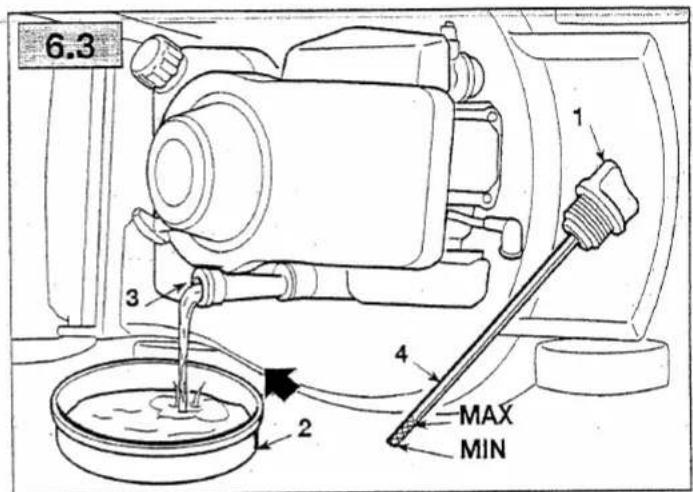
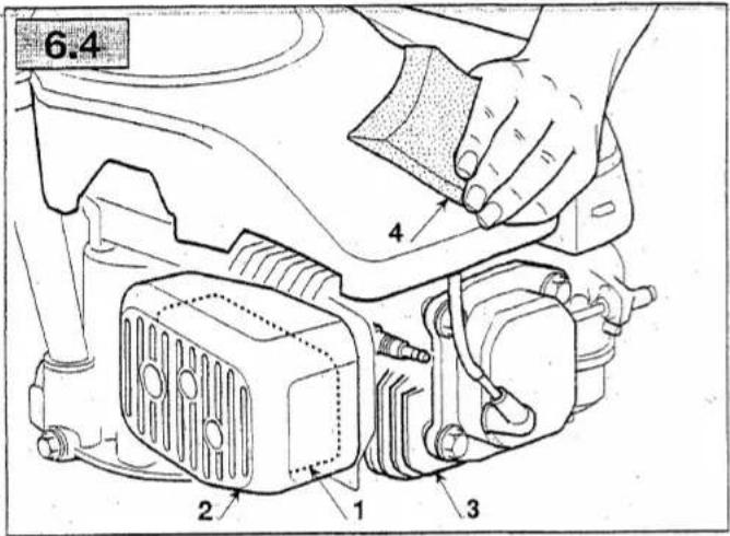
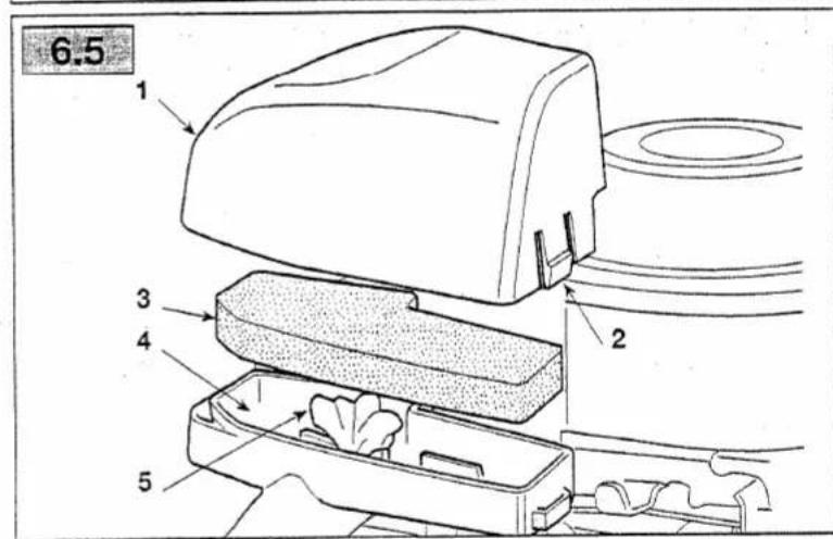


TABLE OF CONTENTS
- General information 1
- Safety regulations 1
- Components and controls 2
- What you need to know 3
- Standards of use 4
- Maintenance 6
- Troubleshooting 8
- Technical data 8
1. GENERAL INFORMATION
1.1 READING AND UNDERSTANDING THE MANUAL
Some paragraphs in the manual containing information of particular importance for safety and operation are highlighted at various levels of emphasis, and signify the following:
NOTE
or
IMPORTANT
These give details or further information on what has already been said, and aim to prevent damage either to the engine or other damages.
WARNING!
Non-observance will re-
sult in the risk of injury to oneself or others.
DANGER!
Non-observance will result in the risk of serious injury or death to oneself or others.
NOTE
Whenever a reference is made to a position on the machine "front", "back", "left" or "right" hand side, this is determined by facing the direction of forward travel.

2. GENERAL SAFETY STANDARDS
(to be strictly applied)
A) TRAINING
1) Read carefully the instructions in this manual as well as those of the lawnmower powered by this engine. Learn how to stop the engine quickly.
2) Never allow people unfamiliar with these instructions to use the engine.
3) Never use the engine while people, especially children, or pets are nearby.
4) Remember that the operator or user is responsible for accidents or hazards occurring to other people or their property.
The number before the paragraph title refers to the text references and their related figures (shown inside front and back covers).
1.2 SAFETY SYMBOLS
Your engine should be used with due care and attention. Symbols have therefore been placed on the engine to remind you of the main precautions to be taken. Their full meaning is explained later on.
You are also asked to carefully read the safety regulations in the applicable chapter of this handbook.

Warning! - Read instructions before using.

Warning! - Keep away from hot surfaces.
B) PREPARATION
1) Do not wear loose-fitting clothing, dangling drawstrings, jewels or items that could become caught; tie up long hair and keep at safe distance (behind the lawnmower handle) while starting the lawnmower.
2) Turn engine OFF and let it cool before removing gas cap.
3) WARNING: DANGER! Fuel is highly flammable:
- store the fuel in special containers;
- refuel only outdoors by using a funnel; never smoke while refueling and/or handling fuel;
- add fuel before starting the engine. Never remove the cap of the fuel tank or add fuel while the engine is running or when the
4. WHAT YOU NEED TO KNOW
The engine performance, reliability and life are influenced by many factors, some external and some strictly associated with the quality of the products used and with the scheduled maintenance.
The following information allow a better understanding and use of your engine.
4.1 ENVIRONMENTAL CONDITIONS
The operation of a four-stroke endothermic engine is affected by:
a) Temperature:
- Working in low temperatures could lead to a difficult cold starting.
- Working in very high temperatures could lead to a difficult hot starting due to the evaporation of the fuel either in the carburetor float chamber or in the pump.
- In any case, the right kind of oil must be used, according to the operating temperatures.
b) Altitude:
- The higher the altitude (above sea level), the lower the max power developed by an endothermic engine.
- Therefore, at the highest altitudes the load on the lawnmower should be reduced avoiding, for example, to cut tall or wet grass.
4.2 FUEL
A good quality fuel is the major issue for the engine reliability of operation.
a) Use unleaded gasoline, with a minimum of 90 octane.
b) Use clean, fresh fuel; purchase fuel in quantity that can be used within 30 days, to prevent gum from forming inside the container or the tank.
c) Do not use fuel which contains Methanol.
d) Do not add neither oil nor any kind of fuel additive.
4.3 OIL
Use always high quality oils, choosing their viscosity grade according to the operating temperature.
a) Use only detergent oil classified SF-SG.
b) Choose the SAE viscosity grade of oil from this chart:
- from 5 to 35 °C = SAE 30
- from -15 to + 5 °C = 5W-30 or 10W-30
(Multi-viscosity)
- from -25 to + 35 °C = Synthetic oils 5W-30
or 10W-30
(Multi-viscosity)
c) The use of multi-viscosity oils in hot temperatures will result in higher than normal oil consumption; therefore, check oil level more frequently.
e) Do not mix oils of different brands and features.
d) SAE 30 oil, if used below 5°C, could result in possible engine damage due to inadequate lubrication.
f) Oil should be at "MAX" mark (see 5.1.1): do not overfill. Overfilling with oil may cause:
- Smoking;
- Spark plug or air filter fouling, which will cause hard starting.
4.4 AIR FILTER
The air filter must always be in perfect working order, to prevent grass cuttings and dust from getting sucked into the engine, reducing the efficiency and life of the machine.
a) Always keep the filtering element free of grass cuttings and in perfect working order (see 6.5).
b) If necessary, replace the filtering element with an original spare part. Incompatible filtering elements can impair the efficiency and life of the engine.
c) Never start the engine without mounting the filtering element properly.
4.5 SPARK PLUG
Not all the spark plugs for endothermic engines are the same!
a) Use only spark plugs of the recommended type, with the right heat range.
b) Check the length of the thread, because - if too long - it will damage the engine beyond repair.
c) Make sure that the electrodes are clean and their gap is correct (see 6.6).
5. STANDARDS OF USE
5.1 BEFORE EVERY USE
Before every use, perform the following checking procedures in order to assure a regular operation.
5.1.1 Check oil level
See the specific chapter (8.1) for the oil to be used.
a) Place engine level.
b) Clean around oil fill.
c) Unscrew the cap (1), clean the end of the dipstick (2) and insert it, as illustrated, without screwing it down.
d) Remove the cap with the dipstick and check the oil level that must be between the "MIN" and "MAX" marks.
e) If oil is required, add oil of the same kind up to the "MAX" mark, being careful not to spill any outside the oil fill.
f) Fully tighten the fillercap (1) and wipe off any spilled oil.
5.1.2 Check air cleaner
The efficacy of the air cleaner is crucial for the good performance of the engine; never start the engine if the filter element is missing, broken or insufficiently saturated with oil.
a) Clean around the filter cover (1).
b) Release the rear clip (2); remove the cover (1) and check the foam element (3) that should be undamaged, clean and well saturated with oil. If not, oil or replace the foam element (3) (see 6.5).
c) Put the cover (1) back.
5.1.3 Adding fuel
IMPORTANT Do not drip petrol onto the plastic parts of the motor or the machine to prevent damaging them and remove all traces of spilt petrol immediately. The warranty does not cover damage to plastic parts caused by petrol.
See "Technical Data" chapter (8.1) for the fuel characteristics.
Add fuel only when the engine is cold.
a) Place the lawnmower level.
b) Clean around the fillercap (1).
c) Remove the fillercap (1).
d) Using a clean funnel (2), fill tank to approximately 10 mm below the inner edge of the filler neck (3), being careful not to spill fuel.
e) Tighten the fillercap (1) back and clean any spilled fuel.
5.1.4 Spark plug cap
Connect the cap (1) of cable to the spark plug (2), making sure that there is no grass or dirt either inside the cap or on the spark plug terminal.
5.2 STARTING THE ENGINE (cold)
Always start the engine with the lawnmower traction drive system (if present) in neutral, or with the gear (if present) in "neutral".
- Move the throttle (1) to "CHOKE".
- On lawnmowers, position the engine brake lever (2) against the handle, as described in the instructions given.
- Manual starting
a) Hold the starter rope grip (3) and pull it slowly until you feel some resistance, then tug the starter rope hard.
b) When the engine starts, let go of the rope.
NOTE If the engine fails to start immediately, repeat the above steps.
• Electric starting (if provided)
a) Turn the starter key (4) as described in the machine's instruction manual.
After a few seconds, slowly move the throttle (1) from "CHOKE" to either "FAST" or "SLOW".
NOTE If the engine starts but does not keep running, repeat the above steps with the throttle on "FAST".
5.3 STARTING THE ENGINE (hot starting)
•) Follow the whole cold-starting procedure with throttle control (1) in "FAST" position.
5.4 USE OF THE ENGINE IN OPERATION
When mowing, use the engine at its max rpm by moving the throttle control to "FAST" position.
WARNING! Keep your hands away from the silencer and surrounding areas that can become extremely hot. With the engine running, do not get loose-fitting clothing (ties, scarves, etc.) or hair closer to the top part of the engine.
IMPORTANT Do not operate on over 20° inclines to prevent malfunctioning of the engine.
5.5 STOPPING THE ENGINE DURING MOWING
a) Move the throttle (1) to "SLOW".
b) Release the brake lever (2) on the lawnmower to stop the engine. In electrically started engines, move the throttle to "STOP", or turn the key (3) (if present) to "OFF".
5.6 STOPPING THE ENGINE AFTER MOWING
a) Move the throttle (1) to "SLOW".
b) Release the brake lever (2) on the lawnmower to stop the engine. In the case of electrically started engines, move the throttle to "STOP", or turn the key (3) (if present) to "OFF"
c) When the engine is cold, disconnect the spark plug and remove the key (3) (if present).
d) Remove any grass cuttings from the engine and especially around the exhaust silencer to reduce the risk of fire.
5.7 CLEANING AND STORAGE
a) Do not spray with water or use hydraulic lances to clean the exterior of the engine.
b) Use an airgun (max 6 bar) making sure that no grass debris and dust fall inside the engine.
c) Store the lawnmower (and the engine) in a dry place, sheltered from severe weather conditions and sufficiently ventilated.
5.8 LONG STORAGE (over 30 days)
In case the engine has to be stored for a long time (for example at the end of the season), a few precautions are needed to help the future start-up.
a) Drain fuel from tank to prevent build-ups inside the tank.
b) Remove the spark plug and pour inside the spark plug hole about 3 cl of clean engine oil. Close the hole with a cloth, then pull, slowly and carefully, the starting rope so that, with a few engine revolutions, the oil will be distributed on the cylinder inner walls. Reinstall the spark plug without connecting the cable cap..
6. MAINTENANCE
6.1 SAFETY RECOMMENDATIONS
WARNING!
WARNING! Remove the spark plug cap and read instructions before carrying out any cleaning, repair or maintenance operation. Wear proper clothing and working gloves whenever your hands are at risk. Do not perform maintenance or repair operations without the necessary tools and technical knowledge.
IMPORTANT
IMPORTANT Never get rid of used oil, fuel or other pollutants in unauthorised places.
IMPORTANT
IMPORTANT If necessary, you can lift the front side of your lawnmower or you can tip it on its right side only, making sure not to spill any fuel or oil.
Follow the hourly or calendar – whichever occur first – maintenance schedule shown in the following table.
| Operation | After First 5 hours | Every 5 hours or daily | Every 25 hours or every season | Every 50 hours or every season | Every 100 hours |
| Check oil level (see 5.1.1) | - | √ | - | - | - |
| Change oil 1)(see 6.3) | √ | - | - | √ | - |
| Clean silencer and engine (see 6.4) | - | - | √ | - | - |
| Check air cleaner 2)(see 6.5) | - | - | √ | - | - |
| Oil air cleaner 2)(see 6.5) | - | - | √ | - | - |
| Check spark plug (see 6.6) | - | - | √ | - | - |
| Replace spark plug (see 6.6) | - | - | - | √ | - |
1) Change oil every 25 hours if the engine is operating under heavy load or in ht weather.
2) Clean air cleaner more frequently if the machine is operating in dusty areas.
6.3 CHANGE OIL
See the specific chapter (8.1) for the oil to be used.
WARNING!
Drain oil while the engine
is warm, being careful not to touch the hot engine nor the drained oil.
a) Place engine level.
b) Make sure that the fuel tank is not full and that the cap is properly closed.
c) Clean around oil fill (1).
d) Remove the fillercap (1).
e) Have a container ready (2) to collect the oil.
f) Tip the lawnmower on its right side so that the oil will drain from the oil fill (3).
g) Place the lawnmower level and top up with new oil (see 5.1.1).
h) Check the oil level on the dipstick (4). Oil should be at "MAX" mark.
j) Close the fillercap and wipe off any spilled oil.
NOTE
The oil capacity is about
0.65 liter.
6.4 CLEAN SILENCER AND ENGINE
Silencer must be cleaned when the engine is cold.
a) Remove from the silencer (1) and its guard (2) any grass debris or dirt that could cause fire, using a brush or compressed air.
b) Clean the cylinder and cylinder head fins (3) to ease engine cooling and prevent overheating.
c) Clean the plastic components with a sponge (4) soaked in water and detergent.
6.5 AIR CLEANER SERVICE
Keep the filter clean and oil saturated. Replace it if broken, cut or with damaged parts.
IMPORTANT
Never use compressed air
to clean the filtering element.
a) Clean around the filter cover (1).
b) Release the rear clip (2); remove the cover (1) and the foam element (3).
c) Block the intake pipe (5) with a cloth to prevent dirt from entering.
d) Wash the foam element in liquid detergent and water. Squeeze dry in a clean cloth.
e) Saturate the foam element with 2 tablespoons of clean engine oil and squeeze it a few times to distribute the oil evenly.
f) Remove excess oil with a clean cloth.
g) Clean the interior of the air cleaner housing (4) from any dust and grass.
h) Install the foam element (3) in its housing and close the cover (1).
If the foam element has been replaced, proceed to oil the new filter as described above in sections e), f), g), h).
6.6 SPARK PLUG SERVICE
a) Remove the spark plug (1) using a spark plug socket wrench (2).
b) Clean the electrodes (3) with a metal brush and remove any carbonaceous build-up.
c) Using a thickness gauge (4), check for the right gap (0.6 - 0.8 mm) between the electrodes.
d) Install the spark plug (1) and tighten with a socket wrench (2).
Replace the spark plug if the electrodes are burnt or if the porcelain is broken or damaged.
WARNING!
Fire hazard! Do not check
the ignition system with spark plug removed.
IMPORTANT
Use only spark plugs of the
recommended type (see 8.1).
6.7 ADJUSTMENT OF THE ACCELERATOR CABLE
If the engine does not reach its maximum rpm with the throttle control in "FAST" position, this is likely due to an out-of-phase connection between the accelerator lever and the governor lever.
To restore the correct phase:
a) Stop the engine, remove the spark plug cap and wait until the engine has cooled.
b) Loosen the screw (1) of the clamp (2) so that the cable casing (3) is free to move.
c) Move the throttle control to "CHOK".
d) Move governor control lever (4) forward as far as possible and, by keeping it in this position, lock the casing (3) full tightening the screw (1) of the clamp (2).
- TROUBLESHOOTING
| PROBLEM | LIKELY CAUSE | SOLUTION |
| a) Hard starting | - No fuel- Stale fuel or build-ups in tank- Spark plug disconnected- Dirty electrodes or incorrect gap- Air filter clogged- Incorrect oil for the season- Fuel evaporation in the carburetor (vapor lock) due to high temperatures- Fault in carburation- Hard starting- Stale fuel or build-ups in tank | - Check and top up (see 5.1.3)- Empty fuel tank and refill with fresh fuel- Check that the spark plug cap fits well over the plug terminals (see 5.1.4)- Check (see 6.6)- Check and clean (see 6.5)- Replace with proper oil (see 6.3)- Wait for a few minutes then start again (see 5.3)- Contact a Licensed Service Centre- Contact a Licensed Service Centre- Empty fuel tank and refill with fresh fuel (see 6.8) |
| b) Inconsistent working | - Dirty electrodes or incorrect gap- Air filter clogged- Fault in carburation- Hard starting | - Check (see 6.6)- Check and clean (see 6.5)- Contact a Licensed Service Centre- Contact a Licensed Service Centre |
| c) Loss of power while mowing | - Air filter clogged- Fault in carburation- Governor out of phase with respect to the accelerator | - Check and clean (see 6.5)- Contact a Licensed Service Centre- Adjust the cable (see 6.7) |
8. TECHNICAL SPECIFICATIONS
8.1 REFILLING AND OPERATION MATERIALS
Fuel Unleaded gasoline, minimum 90 octane
Tank capacity 1.2 liter SAF 30
Engine oil: from 5 to 35 °C....FW 20 or 10W 20
from -15 to +5 °C 5W-30 or 10W-30
from -25 to +35 °C. Synthetic 5W-30 or 10W-30
Oil capacity 0.65 liter PN2VC (Champion) or equivalent
Spark plug ...... RN9YC (Champion) of equivalent 0.6–0.8 mm
Spark plug gap 0.6 - 0.8 mm
GGP ITALY SPA
Via del Lavoro, 6
I-31033 Castelfranco Veneto (TV) ITALY

GLOBAL GARDEN PRODUCTS
CERTIFICATE OF WARRANTY AND OPERATION INSTRUCTIONS FIAMM type FG 20451 12V 4.5Ah VRLA batteries

WARRANTY CONDITIONS
Should an operation fault occur, have the vehicle's electric system checked and the battery charged if it is flat. Any battery which is defective after being charged shall be covered by the warranty terms and conditions applied by the sale network.
In any case, the warranty shall not apply where the defect is caused by improper maintenance or tampering.
SAFETY STANDARDS

It should be borne in mind that the electrolyte is a solution which is diluted in sulphuric acid. In case of contact with your skin, wash thoroughly with water.

If contact is made with your eyes, after washing them thoroughly with water, seek medical advice.

All batteries, while being charged, develop flammable gases that, if triggered, could cause the battery to explode. During charging operations avoid any sparks, live flames and lit cigarettes.

Installed battery: avoid any sparks during installation, removal, checking or start-up operations with jump leads or with auxiliary batteries or equipment; keep away from live flames and cigarettes. Bench charged battery: make sure you correctly connect the battery to the charger (+ with +, - with -). Charge in a ventilated area free from strong draughts avoiding any sparks, live flames or lit cigarettes in the proximity of the battery. Do not place any metal tools on the battery.

Keep out of the reach of children.
USER INSTRUCTIONS AND RECHARGING METHODS
The FIAMM type FG 20451 battery is a sealed battery with a rated 12V voltage controlled by valves. This is a completely maintenance-free battery and does not require any checking of the electrolyte level or any topping up.
Use:
• Never remove the strip on the top of the cover.
- Never remove the strip on the top of the cover.
- If there are breakages of the block, cover, or terminals or if the valve housing strip has been tampered with. REPLACE THE BATTERY.
• Always recharge the battery prior to its first use.
• If the vehicle is idle for over a month, remove the battery and store it in a cool and dry place.
• Recharge the battery completely before reinstalling it.
Recharging methods:
- Recharge the battery, with an open circuit voltage lower than 12.60V. If a battery is left discharged for over a month, it may suffer damage.
- To check the charge status, measure the voltage using a voltmeter. The battery (after it has been recharged) must be resting for at least 12 hours.
- Recharge only with a constant voltage battery charger. If a conventional battery charger (for motorcars) is used, the battery may suffer damage.
To recharge the battery, follow the instructions below.
Before the FIRST USE:
| Slow charge | Fast charge | |
| Constant voltage | 14.40÷14.70 V | 14.40÷14.70 V |
| Max. initial current | 1.0 A | 2.0÷4.0 A |
| Charge life | 12÷24 h | 6÷8 h |
Use fast charging only in emergencies.
To PRESERVE charge, regularly use the type CB03 battery charger supplied with.
Charging in conditions of DEEP DISCHARGE:
Charging in conditions of DEEP DISCHARGE. In the case of batteries that have been kept discharged for prolonged periods of time (more than 15 days) it is recommended that the batteries be charged for at least 48 + 72 hours by means of a type CB03 battery charger at constant current.

- FINISH ASSEMBLY
- DESCRIPTION OF CONTROLS
- GRASS CUTTING
- ROUTINE MAINTENANCE
- IMPORTANT - Regular, careful maintenance is essential for keeping the safety level and original performance of the machine unchanged in time.
- EN SAFETY REGULATIONS TO BE FOLLOWED CAREFULLY
- A) TRAINING
- B) PREPARATION
- C) OPERATION
- E) TRANSPORTATION AND HANDLING
- ETIQUETTE D'IDENTIFICATION ET COMPOSANTS DE LA MACHINE IDENTIFICATION LABEL AND MACHINE COMPONENTS KENNUNGSSCHILD UND MASCHINENBAUTEILE ETICHETTA DI IDENTIFICAZIONE E COMPONENTI DELLA MACCHINA IDENTIFICATIELABEL EN ONDERDELEN VAN DE MACHINE
- DESCRIPTIONS DES SYMBOLES QUI APPARAISSENT SUR LES COMMANDES (là où ils sont prévus) DESCRIPTION OF THE SYMBOLS SHOWN ON THE CONTROLS (where present) BESCHREIBUNG DER SYMBOLE AN DEN STEUERHEBELN (wo vorgesehen) DESCRIZIONE DEI SIMBOLI RIPORTATI SUI COMANDI (dove previsti) BESCHRIJVING VAN DE SYMBOLEN AANGEGEVEN OP DE BEDIENINGEN (indien voorzien)
- SAFETY STANDARDS
- USER INSTRUCTIONS AND RECHARGING METHODS
- Use:
- Recharging methods:
- Charging in conditions of DEEP DISCHARGE:
- Mountfield RM65/ES
- SV200 SV200ES R200 R200ES
- TABLE OF CONTENTS
- GENERAL INFORMATION
- READING AND UNDERSTANDING THE MANUAL
- NOTE
- IMPORTANT
- WARNING!
- DANGER!
- GENERAL SAFETY STANDARDS
- SAFETY SYMBOLS
- WHAT YOU NEED TO KNOW
- ENVIRONMENTAL CONDITIONS
- a) Temperature:
- b) Altitude:
- FUEL
- OIL
- AIR FILTER
- SPARK PLUG
- STANDARDS OF USE
- BEFORE EVERY USE
- Check oil level
- Check air cleaner
- Adding fuel
- Spark plug cap
- STARTING THE ENGINE (cold)
- - Manual starting
- • Electric starting (if provided)
- STARTING THE ENGINE (hot starting)
- USE OF THE ENGINE IN OPERATION
- STOPPING THE ENGINE DURING MOWING
- STOPPING THE ENGINE AFTER MOWING
- CLEANING AND STORAGE
- LONG STORAGE (over 30 days)
- MAINTENANCE
- SAFETY RECOMMENDATIONS
- CHANGE OIL
- CLEAN SILENCER AND ENGINE
- AIR CLEANER SERVICE
- SPARK PLUG SERVICE
- ADJUSTMENT OF THE ACCELERATOR CABLE
- TECHNICAL SPECIFICATIONS
- REFILLING AND OPERATION MATERIALS
- GGP ITALY SPA
- CERTIFICATE OF WARRANTY AND OPERATION INSTRUCTIONS FIAMM type FG 20451 12V 4.5Ah VRLA batteries
- WARRANTY CONDITIONS
Brand : MOUNTFIELD
Model : SP534ES
Category : Lawn mower