
NVR301-04S - Video recorder UniView - Free user manual and instructions
Find the device manual for free NVR301-04S UniView in PDF.


| Product Type | Network Video Recorder |
| Brand | UniView |
| Model | NVR301-04S |
| Channels | 4 Channels |
| Form Factor | 1U Rackmount |
| Dimensions (W x D x H) | 430 mm x 265 mm x 44 mm |
| Weight | Approx. 2.8 kg |
| Power Supply | DC 12V, 2A |
| Power Consumption | ≤ 15W (without HDD) |
| Hard Drive Support | 1 x SATA HDD up to 8TB |
| Video Compression | H.265 / H.264 |
| Recording Resolution | Up to 8MP per channel |
| Network Interface | 1 x RJ45 10/100/1000 Mbps |
| USB Ports | 2 x USB 2.0 |
| Operating System | Embedded Linux |
| Remote Access | Via web browser or mobile app |
| Maintenance & Cleaning | Use a soft, dry cloth; avoid liquids |
| Safety Precautions | Ensure proper ventilation; use only supplied power adapter |
| Spare Parts / Repairability | Hard drive and power adapter are user-replaceable; consult service manual |
| Included Accessories | Power adapter, mouse, mounting ears, user manual |
Frequently Asked Questions - NVR301-04S UniView
User questions about NVR301-04S UniView
0 question about this device. Answer the ones you know or ask your own.
Ask a new question about this device
Download the instructions for your Video recorder in PDF format for free! Find your manual NVR301-04S - UniView and take your electronic device back in hand. On this page are published all the documents necessary for the use of your device. NVR301-04S by UniView.
USER MANUAL NVR301-04S UniView
Network Video Recorders
User Manual
Thank you for purchasing our product. Contact your local dealer if you have any quesons or feedback. No part of this manual may be copied, reproduced, translated, or distributed in any form or by any means without prior consent in wring from our company.
Disclaimer

CAUTION!
The default password is intended only for your rst login. We strongly recommend you set a strong password to ensure account security.
- Strong: contains at least 8 characters from at least three of the four types: upper-case leer, lower-case leer, special character, digit.
- Medium: contains at least 8 characters from two of the four types: upper-case leer, lower-case leer, special character, digit.
-
Weak: contains less than 8 characters from only one of the four types: upper-case leer, lower-case leer, special character, digit.
-
To the maximum extent permied by applicable law, the product described, with its hardware, soware, rmware and documents, is provided on an "as is" basis.
- Best eort has been made to verify the integrity and correctness of the contents in this manual, but no statement, informaon, or recommendaon in this manual shall constute formal guarantee of any kind, expressed or implied. We shall not be held responsible for any technical or typographical errors in this manual. The contents of this manual are subject to change without prior noce. Update will be added to the new version of this manual.
- Use of this manual and the product and the subsequent result shall be enrely on the user's own responsibility. In no event shall we be liable for any special, consequential, incidental, or indirect damages, including, among others, damages for loss of business prots, business interrupon, or loss of data or documentaon, or
product malfuncon or informaon leakage caused by cyber aack, hacking or virus in conneccon with the use of this product.
- Video and audio surveillance can be regulated by laws that vary from country to country. Check the law in your local region before using this product for surveillance purposes. We shall not be held responsible for any consequences resulting from illegal operaons of the device.
- The illustraons in this manual are for reference only and may vary depending on the version or model. The screenshots in this manual may have been customized to meet specific requirements and user preferences. As a result, some of the examples and funcons featured may dier from those displayed on your monitor.
- This manual is a guide for mulple product models and so it is not intended for any specific product.
- Due to uncertaines such as physical environment, discrepancy may exist between the actual values and reference values provided in this manual. The ulmate right to interpretaon resides in our company.
Safety Symbols
The symbols in the following table may be found in this manual. Carefully follow the instrucons indicated by the symbols to avoid hazardous situaons and use the product properly.
| Symbol | Descripon |
 WARNING! WARNING! | Indicates a hazardous situaon which, if not avoided, could result in bodily injury or death. |
 CAUTION! CAUTION! | Indicates a situaon which, if not avoided, could result in damage, data loss or malfuncon to product. |
 NOTE! NOTE! | Indicates useful or supplemental informaon about the use of product. |
Contents
Preface ....1
Part I Local Operaons ....1
1 Before You Begin....1
Login....2
Local Operaons 2
2 Inial Conguration....7
Preparaon 7
Wizard 7
3 Live View....11
Live View Status ....11
Window Toolbar 12
Screen Toolbar 13
Shortcut Menu 14
Sequence Operaon ....15
Zoom 16
Image Conguraon ....17
Preview Conguraon ....18
4 Channel Configuraon 20
Channel Management....20
OSD Conguraon 31
Image Conguraon ....31
Privacy Mask Conguraon 35
5 PTZ Control....36
PTZ Control Window and PTZ Management Window 36
Seng and Calling a Preset 38
Seng a Preset Patrol ....39
Seng a Recorded Patrol 40
Seng Auto Guard 41
6 Recording and Snapshot ....41
Encoding Sengs....42
Draw or Edit a Schedule....45
Scheduled Recording and Snapshot....46
Moon Detecon Recording and Snapshot....46
Alarm Triggered Recording and Snapshot 49
Manual Recording and Snapshot ....50
Holiday Recording and Snapshot ....51
Other Recording and Snapshot Types....52
7 Playback....53
Instant Playback ....53
Playback Toolbar 53
Playback by Camera and Date....55
Playback in Corridor Mode....56
Playback by Tag....56
Playback by Event 57
Playback by Smart Search ....57
Playback by External File....58
Playback by Image....58
Playback by POS....58
File Management ....59
8 Backup....60
Recording Backup 60
Image Backup....62
9 Alarm....62
Alarm Input and Output....62
Moon Detecon....65
Tampering Detecon 66
Video Loss 67
VCA....67
Defocus Detecon....72
Scene Change Detecon ....73
Auto Tracking....73
Alert 75
Buzzer....76
Alarm-Triggered Acons 76
Manual Alarm 77
10 VCA Search....77
Behavior Search ....77
Face Search 78
People Counng....79
11 Network Conguraon ....80
TCP/IP....80
PPPoE 82
EZCloud 82
DDNS....83
3G/4G....84
Port 85
Port Mapping 86
Email....88
FTP....89
SNMP....91
Mulcast 92
12 Disk Configuraon 92
Disk Management 92
Array Conguraon....94
Disk Group....96
Space Allocaon....97
Advanced Conguraon 98
Hard Disk Detecon 98
13 System Conguration.... 101
Basic Conguraon ....101
Time Conguraon ....102
Transacon Conguraon....103
Serial Port Conguraon....104
User Conguraon....105
Security Conguraon ....106
Hot Spare Conguraon 109
14 System Maintenance .... 110
System Informaon....110
Network Informaon 112
Log Query....115
Import/Export 116
System Restoraon 117
Automac Maintenance ....118
System Upgrade....118
15 Shutdown.... 119
Part II Web-Based Operaons....119
1 Before You Begin....119
2 Login....120
3 Live View....121
4 Playback....123
5 Conguraon 124
Appendix A Typical Applicaons 126
Typical Applicaon 1....126
Typical Applicaon 2....126
Typical Applicaon 3....127
Appendix B Acronyms....127
Appendix C FAQs....128
Preface
This manual describes how to use your NVR locally or on the Web interface.
In this manual, the terms IP camera and IPC refer to the same thing: network camera, which requires a conncon to the network. And the IP device menoned in this manual refers to an IP camera (also known as network camera) or a Digital Video Server (DVS).
Part I Local Operaons
An NVR supports two types of operaons: local operaons and web-based remote operaons. With local operaons you connect a monitor and a mouse to the NVR and use the mouse to operate. If your NVR has buons on the front panel or is delivered with a remote control, you may also control your NVR by pressing the front panel buons or using the remote control.
The NVR has an embedded web server and allows web-based operaons. To do this, you need a PC that has a network conncon to the NVR and is installed with a web browser. You just need to navigate to the NVR's IP address and log in to the Web interface like you log in to the system locally.
This secon describes local operaons.
1 Before You Begin
Please be aware that the parameters that are grayed out on the system user interface (UI) cannot be modified. The parameters and values displayed may vary with device model, and the gures in this manual are for illustraon purpose only.
Login
Use the default username admin and password 123456 for your rst login.
CAUTION!
The default password is intended only for the rst login and should be changed to a strong one containing at least eight characters includir uppercase and lowercase leers, digits and symbols aer your rst login to ensure security.
- Right-click anywhere in the window and then choose Menu. The login dialog box is displayed.
- Select the username from the drop-down list, enter your password, and then click Login.
Local Operaons
You can refer to Inial Conguraon and complete a quick conguraon.
NOTE!
Unless otherwise specified, all operaons described in this manual are performed with a mouse by the right hand. See Mouse Operaons for details.
Mouse Operaons
Table 1-1 Mouse Operaons
| Name | Acon | Descripon |
| Le buon | Click | Select or conrm an item.Select to edit digits, symbols, upper-case or lower-case leers in a eld. |
| Double-click | Enter or exit full screen mode in live view. | |
| Drag | Draw or move a rectangle on the screen, forexample, a moon detecon area. | |
| Right buon | Click | Show the shortcut menu.Exit zoom.Exit the current window when Cancel or Exit is displayed. |
| Wheel | Scroll up or down | Scroll up or down a list or a window; or zoom in or out on a playback progress bar. |
Front Panel Buons
The front panel buons may vary with NVR model.
Table 1-2 Front Panel Buons 1
| Buon | Descripon | |
 | Display the main menu. | |
 | Switch to the next tab on the screen or switch the input method. | |
 | Auxiliary funcon buon. | |
 | Exit the current window. | |
 | △, ▽, ▷, ◀: Switch windows or menu items; or control rotaon direcons of a PTZ camera when the PTZ toolbar is closed. PTZ stands for pan, lt, and zoom. ◀, ◀: Rewind or forward 30 seconds in full screen. ◀, ◀: Variable-speed forward or rewind in full screen. | |
 | Conrm an operaon, or start/pause the playback. | |
 | Press this buon to start up or shut down the NVR.To shut down, press this buon and hold for at least 3 seconds ll a message appears on your monitor. Click Yes.Note:This shutdown operaon can be performed only when you have logged in to the system. | |
Table 1-3 Front Panel Buons 2
| Buon | Descripon |
 | Press this buon to start up or shut down the NVR.To shut down, press this buon and hold for at least 3 seconds ll a message appears on your monitor. Click Yes.Note:This shutdown operaon can be performed only when you have logged in to the system. |
 | Enter 1; or display the main menu. |
 | Enter 2, A, B, or C; or start instant playback. |
 | Enter 3, D, E, or F; or start manual recording. |
 | Enter 4, G, H, or I; or enter the PTZ control interface. |
 | Enter 5, J, K, or L; or switch the screen layout in live view or playback mode. |
 | Enter 6, M, N, or O; or enable or disable arming. |
 | Enter 7, P, Q, R, or S; or take a snapshot. |
 | Enter 8, T, U, or V. |
 | Enter 9, W, X, Y, or Z. |
 | Enter 0 or a space. |
 | Delete |
 | Switch the input method. |
 | Auxiliary funcon buon. |
 | Exit the current window. |
 | Switch to the next tab. |
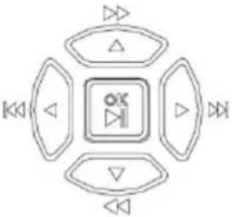 | △, ▽, ▷, ◀: Switch windows or menu items; or control rotaon direcons of a PTZ camera when the PTZ toolbar is closed■□□, ▽□: Rewind or forward 30 seconds in full screen.■◇◇, ◀◇: Variable-speed forward or rewind in full screen.OK◇◇: Conrm an operaon; or start or pause |
| playback. |
Remote Control
Table 1-4 Funcons of the Buons on the Remote Control
| Buon | Funcon |
| Power | Press this buon to start up or shut down the NVR.To shut down, press this buon and hold for at least 3 seconds ll a message appears on your monitor. Click Yes.Note:This shutdown operaon can be performed only when you have logged in to the system. |
| DEV | This buon is for reserved funcons. |
| Toolbar | In live view mode, press this buon to show the toolbar for the currently selected window.In playback mode, press this buon to display windows according to the congured screen layout. |
| Menu | Press this buon to display the main menu. |
| Iris+/Iris- | Adjust the iris, focus and zoom of the PTZ camera in PTZ control mode. |
| Focus+/Focus- | |
| Zoom+/Zoom- | |
| UP, DOWN, LEFT, RIGHT, ENTER | Press UP, DOWN, LEFT and RIGHT to navigate between menu items or shi focus.In PTZ control mode, press UP, DOWN, LEFT, and RIGHT buons to select the corresponding buons on the screen, and then press ENTER to acvate the selecon.In live view mode, press UP to start sequence in full screen. Pressing UP again starts sequence with three windows on the screen. Press DOWN to open the playback window.Press ENTER to conrm an operaon or to display a selected drop-down list. In playback mode, press ENTER to play or pause in full screen mode.• UP and DOWN: Variable speed forward or rewind in full screen.• LEFT and RIGHT: Rewind or forward 30 seconds in full screen. |
| Fn | Press to navigate to the next window when mulple windows are displayed. |
| Esc | Exit. |
| Alphanumeric buons | • Switch to the corresponding channel in live view mode.• Input numbers and characters in edit mode. |
| Shi | Switch menu items. |
| Del | Remove characters or spaces on the le of the cursor. |
2 Inial Conguraon
Preparaon
- Make sure that at least one monitor is correctly connected to the VGA or HDMI interface on the rear panel of the NVR.
- Verify that the hard disk(s) are correctly installed. For detailed steps to install a hard disk, please refer to the quick guide shipped with your NVR.
Wizard
The wizard can guide you to complete the most basic setup. The wizard may vary with device model and other factors. The following shows an example.
- Enable or disable the wizard as needed and then click Next.

NOTE!
• You may change the seng under System > Basic.
- If a QR code is displayed, you may scan the code to download an app and use the app to control your NVR.
2. Enter the default admin password 123456 and then click Next.

CAUTION!
The default password is intended only for the rst login and should be changed to a strong one containing at least eight characters including uppercase and lowercase leers, digits and symbols aer your rst login to ensure account security.


NOTE!
For RAID models, a window appears following this step for RAID conguraon.
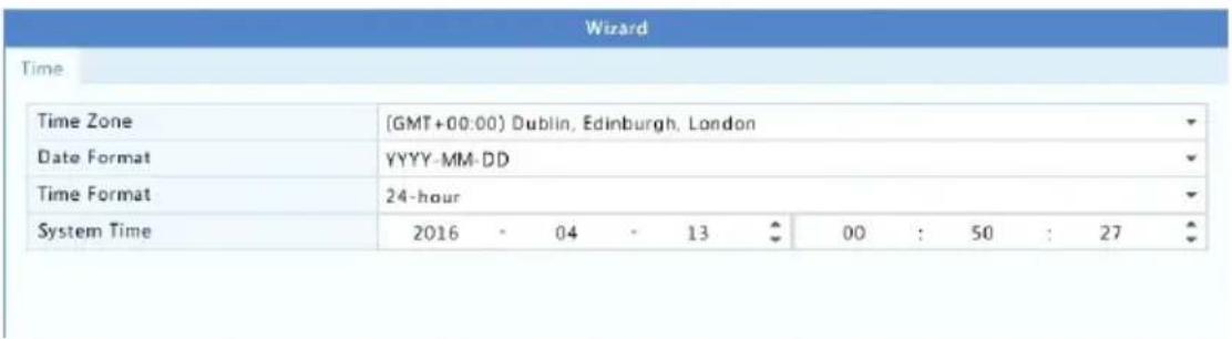
3. Complete me informaon and then click Next.
- Set the IP address, subnet mask, and default gateway. Use the default sengs for other parameters unless modicaon is necessary. Review the sengs and then click Next.
| Wizard | |
| Basic | |
| Select NIC | NIC1 |
| Enable DHCP | ☐ |
| IPv4 Address | 204 - 4 - 1 - 90 |
| IPv4 Subnet Mask | 255 - 255 - 255 - 0 |
| IPv4 Default Gateway | 204 - 4 - 1 - 1 |
| MAC Address | 48:ea:63:0e:14:06 |
| MTU (Bytes) | 1500 |
| Preferred DNS Server | 8 - 8 - 8 - 8 |
| Alternate DNS Server | 8 - 8 - 4 - 4 |
| Internal NIC IPv4 Addr. | 172 - 16 - 0 - 1 |

NOTE!
- DHCP is enabled by default.
- If your NVR has more than one Network Interface Card (NIC), you may congregate the NICs and choose one for default route.
-
An internal IPv4 address can be congured if your NVR has PoE ports or switching ports.
-
Click Search. The detected IP devices are listed. Select the device(s) to add and then click Add.
- Click Next.

7. Set a recording/snapshot schedule and then click OK.

bar
| Day | Time | |-------|------| | Mon | 0 | | Tue | 2 | | Wed | 4 | | Thu | 6 | | Fri | 8 | | Sat | 10 | | Sun | 12 | | Holiday | 14 | | Mon | 16 | | Tue | 18 | | Wed | 20 | | Thu | 22 | | Fri | 24 | (Note: Click a color on the right and then draw the schedule.) Copy Previous OK ExitYou may also edit wizard sengs by clicking Wizard under System > Basic.
3 Live View
Live View Status
The following icons are used to indicate alarms, recording status, and audio status in a live view window.
Table 3-1 Live View Window Icons
| Icon | Descripon | |
 | Tampering alarm | |
 | Moon detecon alarm | |
 | Recording | |
 | Two-way audio | |
 | Turn on audio | |
Normally, live video is displayed, but other situaons are also possible.

| No. | Descripon |
| 1 | The IP device is online, and live video is displayed. |
| 2 | The IP device is online, but the NVR has insucient capacity to decode streams from the IP device. |
| 3 | No permission to view live video from the IP device. |
| 4 | The IP device is oine. |
| 5 | No IP device is linked to the window. |
Window Toolbar
| Icon | Descripon |
 | Available for PTZ cameras only. Click to display the PTZ control window. |
 | Set mount mode and display mode for sheye camera.This icon appears only for sheye cameras. |
 | Record live video in the window to the hard disk.Clicking stops recording. |
 | Click to play video recorded during the past 5 minutes and 30 seconds. |
 | Zoom in on an area of interest. |
 | Click to edit image sengs. |
 | Click to take a snapshot. The window borders will ash white.You may view and back up snapshots under Backup > Image. |
 | Rest your mouse pointer on the icon to view live video informaon. Or click it to view the channel number, camera name, IP address, conncon status and recording status. |
  | Start two-way audio with the camera. Click to stop. The sound volume is adjustable.Note: Correct audio input and output conncons are required. |
 [IMAGE] [IMAGE] | Click to turn on audio. Clicking turns o audio. The sound volume is adjustable.Note: When you turn on audio in the current window, audio of the previous window is turned o. |
| Icon | Descripon | |
 | Click to link the window to another IP device. | |
 | Exit | |
Screen Toolbar
| Icon | Descripon |
 | Click to access the main menu. |
 //A4W7 //A4W7 | Select the screen layout. |
 / / | Previous or next screen. |
 / / | Start or stop sequence. |
 | Playback. |
 | Click to open the USB Device window and perform USB related operaons. The window oers quick access to mulple windows, and it pops up automacally if a USB storage device is plugged in when the NVR is restarng or when the preview window is displayed.This buon is eecve only when a USB storage device is plugged in. |
 | Rest the mouse pointer on this icon to view encoding informaon including frame rate, bit rate, and resoluon; or click to view camera status. |
 | Click to view device alarm status and camera status. |
 | Rest the mouse pointer on it to view NIC card informaon. Or click this icon to edit basic network sengs. |
 | Rest the mouse pointer on it to view the date. Or click this icon to edit me sengs. |
 | Available to certain NVR models.Click to display the cloud service window. You may scan the QR code and download an app to manage your NVR. |
 | Click to automatically hide the toolbar, or click lock.  |
Shortcut Menu
A shortcut menu as shown below appears when you right-click in a window. Some menu items are described in Shortcut Menu Descripon.
Table 3-2 Shortcut Menu

Table 3-3 Shortcut Menu Descripon
| Menu | Descripon |
| Menu | Access the main menu.Most of operaons described in this manual are performed start from the main menu; for example, click Camera > Camera (with Menu > omied). |
| Corridor | Choose a corridor mode. Corridor mode can also be set in the Default Layout drop-down list under System > Preview.To display images in corridor mode, the camera must be installed correctly (rotated 90° clockwise or counterclockwise), and then use the Image Rotaon parameter under Camera > Image to rotate images accordingly. |
| Main/Aux Monitor | Switch live video from dierent video output. |
| Fisheye Mode | Set mount mode and display mode for sheye camera. |
| PTZ Control | Display the PTZ control window for the rst PTZ camera in live view. |
| Playback | Play the current day's recording for the camera linked to the current window. |
| Output Mode | Choose a video output mode, including standard, so, bright, and vivid. |
Sequence Operaon
The sequence operaon requires you to congregate the screen layout, windows, linked cameras, and the sequence interval.
This example describes how to congregate sequence for ve cameras based on a 4-window screen layout.
- Click 4 Windows on the screen toolbar.

NOTE!
The number of windows that can be displayed may vary with NVR model.
- Click Start Sequence on the screen toolbar. Sequence starts by displaying four windows on the rst screen and then the h on the second screen at the set interval.
NOTE!
- The default sequence interval is eight seconds and can be set under System >Preview.
- You may drag video to the desired window on the screen.
Zoom
Zoom in on an area of images in a window for details.
- Click the window and then click on the window toolbar.
- In the small window in the lower right corner, click and drag your mouse to specify the area to zoom in on. The image in the main window zooms in. The following shows an example.

natural_image
Yellow heavy-duty truck driving on a multi-lane highway, with traffic and a highlighted section showing a yellow cab (no visible text or symbols)
NOTE!
The system adjusts the area automacally according to the window size and its aspect rao. Also, the system has specied a minimum size to ensure zoom eects.
Image Conguraon
Adjust image sengs to get opmal images from a camera.
-
Click the window and then click on the window toolbar.
-
Select a mode from the drop-down list according to the surveillance scenario, and then adjust contrast, hue, saturon and brightness as needed. The sengs available may vary with device model.
-
Click OK to save the sengs and exit.
Preview Conguraon
Normally, live view (video) is available aer you complete the basic setup by following the wizard. You can click System >Preview and edit preview seng as needed, including video output, image resolution, default layout, and sequence interval. The video output and the number of windows supported may vary with NVR model.

NOTE!
Pressing and holding the scroll wheel for at least 3 seconds will restore the default resoluon.
Preview Conguraon
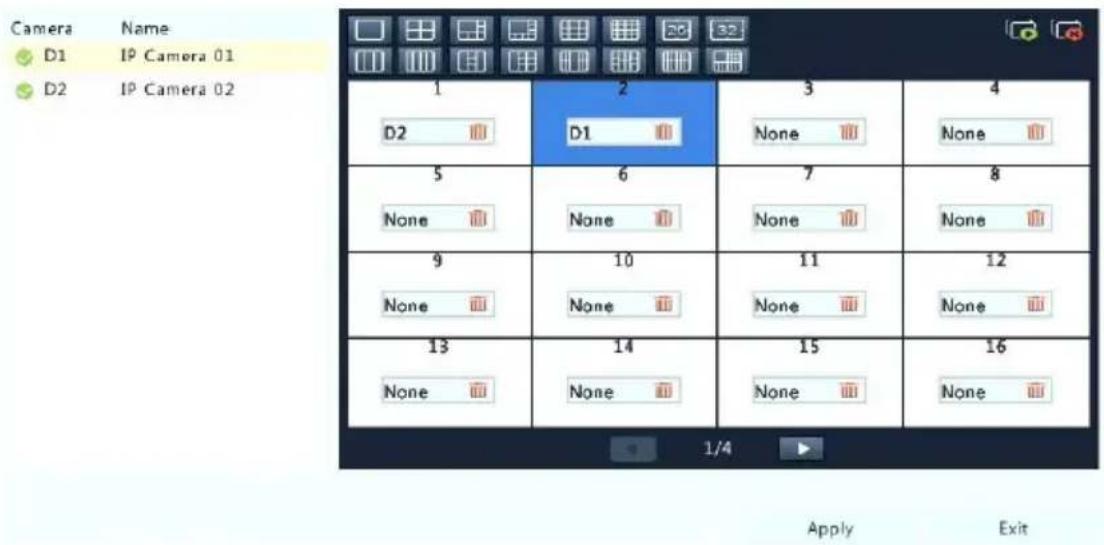
Each preview window (window for short) links to a camera. By default, window 1 links to camera D1, window 2 links to camera D2, and so on. You may want to change the link to display live video from a camera in another specied window. The following example describes how to link window 1 to camera D2 and link window 2 to camera D1.
Step 1: Click window 1 on the right, and then click D2 under Camera on the le. Now D2 appears in window 1, and None appears in window 2. Meanwhile, is cleared for camera D1, meaning D1 is not linked to any window.

Step 2: Click window 2 on the right, and then click D1 under Camera on the le. Now D1 appears in window 2. Click Apply to save the sengs.
Advanced Conguraon
Click the Advanced tab and then select Sub Stream First so the NVR uses the sub stream to establish live video from mulple cameras simultaneously. This funcon is disabled by default.
4 Channel Conguraon
Channel Management
This chapter describes how to add and manage IP devices in your NVR. The IP devices menoned in this manual mainly refer to IP camera (or network camera); somemes they can also be Digital Video Server (DVS). Before you start, make sure the IP devices are connected to your NVR via network.

CAUTION!
An IP device should be connected to one NVR only. An IP device managed by mulple NVRs may cause unwanted issues.
Adding an IP Device
This secon provides mulple opons to add an IP device. Some opons are only applicable to certain NVR models. Choose one as appropriate.
Opon 1
- Click Camera > Camera > Camera. The system automacally searches for IP devices and lists the discovered.
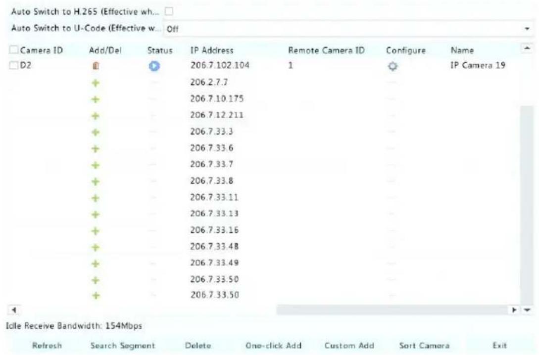

NOTE!
- under Status means an IP device is added successfully, and you may click to view live video from the IP device. - means the IP device is oine, and you may view the cause by resng the mouse pointer on the
-
The idle bandwidth is displayed to indicate current bandwidth available for receiving streams. For more details, see Network Stascs.
-
(Oponal) To search a specied network segment, click Search and then set the address range.
-
Click for the IP device to add. Or, you may also
-
Click One-click Add to add all the discovered IP devices allowed (depending on channels supported by the NVR).
- Click Custom Add. In the window displayed, enter the IP address and complete other sengs, and then click Add. You may also click Search and add discovered cameras in the list.
For a Digital Video Server (DVS), a window appears when you click Add, and you need to select channels to add the connected cameras.
Opon 2
This opon is not applicable to NVRs with PoE ports or switching ports.
- Click in a window.

natural_image
Pure black background with a small white plus sign in the center (no text or symbols)- Select the desired IP device and then click Add.
Opon 3
This opon is only applicable to NVRs with PoE ports or switching ports. Connect an IP camera to a PoE port or a switching port with a network cable. The connected camera will be added to the NVR automacally. Check status under Camera > Camera > Camera. 🚙 means live video from the camera is available. Click 🔒 to view live video.
If the camera is connected via a network switch, click 📄 under Edit. In the window displayed, set Add Mode to Manual and then complete the sengs correctly.

NOTE!
appears under Status if the power output from a PoE port is below or above the rated power of the connected camera.
Opon 4
Use this opon to add an IP device that is connected to a dierent router, for example, when the NVR and the IP device are connected across the Internet.

NOTE!
First you need to enable port mapping at Setup > Port > Port Mapping on the IP device's Web interface.
-
Click Camera > Camera, click Custom Add.
-
Choose an opon:
- By IP
a. On the IP device's Web interface, go to Setup > Port > Port Mapping, nd the external IP (public IP) and external port number.
b. On the NVR: Select a protocol, enter the above-menoned IP address and port number, enter the username and password.
c. Click OK.
- By EZDDNS
a. On the IP device's Web interface, go to Setup > Network > DDNS, enable DDNS, select EZDDNS, set a domain name and get the server address.

NOTE!
- Aer seng the domain name, check that you can use the device address to access the IP device's Web interface.
- Make sure the EZDDNS server and the NVR are connected (ping the EZDDNS server from the NVR).
b. On the NVR: Select a protocol, enter the above-menoned server address, domain name, username and password.
c. Click OK.
- By a domain name
a. On the IP device's Web interface, go to Setup > Network > DDNS, enable DDNS, select DynDNS or NO-IP, enter the domain name that you have signed up on the DNS website, enter the username and password, and then click Save.
b. On the NVR: Select a protocol, enter the domain name menoned above, enter the username and password. The port is the external port of the IP device.
c. Click OK.

NOTE!
- If Custom is selected for Protocol, the port is the mapped external RTSP port of the IP device.
- Do not add an IP device to an NVR using dierent methods (e.g., IP and EZDDNS) at the same me.
- When an IP device is added by EZDDNS, domain name (NO-IP or DynDNS), or IP (public IP+public port) and it is not connected to the same router as the NVR, alarm is congorable, but alarm push is not available.
Opon 5
Use this opon only when the IP device to add supports the standard RTSP, and all you need from the IP device are just view live and playback. IP devices added in this way cannot be congured from the NVR.
- Click Camera > Camera.
- Click Custom Add.
- Click to select a camera in the list, select Custom from the Protocol drop-down list, and then click the Protocol buon.
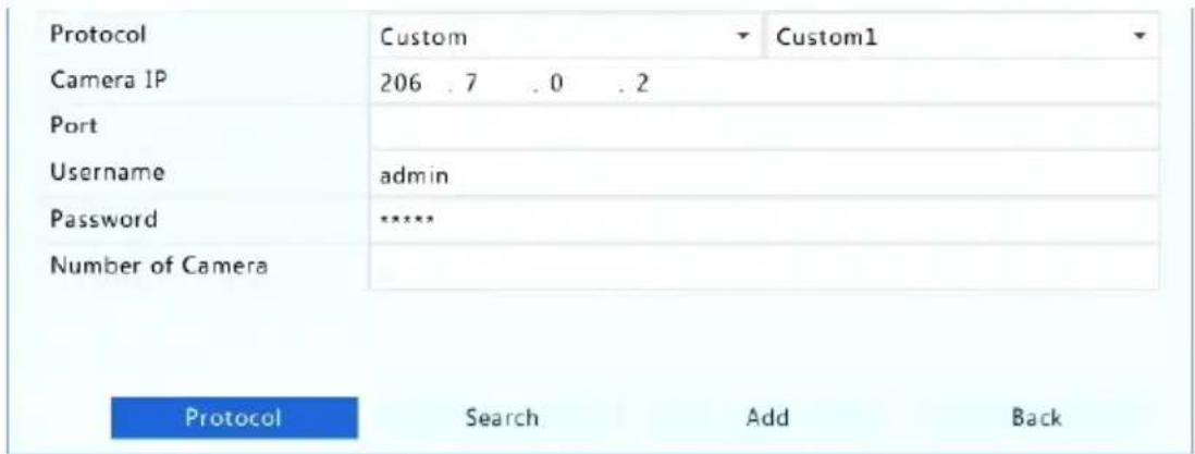
- In the Protocol window, name the protocol, enter the RTSP port number, select a transmission protocol, input the resource paths, and then click Apply.

NOTE!
Contact the camera manufacturer for resource paths.
| Custom | Custom1 |
| Protocol Name | Custom1 |
| Port | 554 |
| Transmission Protocol | UDP |
| Enable Main Stream | |
| Resource Path | rtsp://:/ |
| Enable Sub Stream | |
| Resource Path | rtsp://:/ |
- Edit sengs in the Add/Modify window as needed, including the IP address, username and password, and then click Add. Check status in the camera list.
Managing an IP Device
Manage IP devices under Camera > Camera > Camera.
- Click to edit sengs including the protocol, IP address, port number, username and password. The Camera IP eld displays the IP address that the current channel links to, and you may change the address so the channel links to another device. The username and password must be consistent with that of the IP camera.
- Click 📋 to delete an IP device, or select mulple IP devices and then click Delete. Channels corresponding to PoE ports or switching ports cannot be deleted.
- Click ⚙ to change the IP address of an IP camera and the default gateway. A DVS' IP address cannot be edied from the NVR. — means this funcon is not available.
Sort Cameras
Sort cameras to display in the desired order.

NOTE!
- This funcon is unavailable to NVRs with PoE ports or switching ports.
- This chapter describes how to sort cameras on an NVR with more than 32 channels. For NVRs with 32 channels or less, you can so cameras by dragging the mouse.
For example, to switch channel 1 with channel 4, click Sort Camera, and then follow the steps below:
- In the le list, select the check box for channel 1, and then click

Channel 1 now appears in the right list. Perform the same
operaons to channel 4.
-
In the right list, select channel 4 and then click ←. Now channel 4 appears at the previous line of channel 1 in the list. Perform the same operaons to channel 1, so channel 1 appears at the previous line of channel 4 in the list.
-
Click Apply to save the seng, and then click Yes.
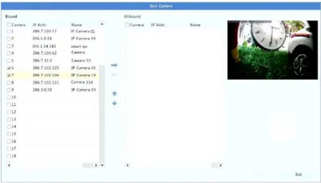

NOTE!
- To move a channel le or right, select the check box rst; otherwise, the buons are grayed.
- To move a channel up or down, click the channel rst; otherwise, the buons are grayed.
- A channel will be inserted to the rst blank line in the le list unless you have specied another line in the list by selecng the corresponding check box.
- Save cannot be clicked when the right list is not empty. You need to clear the list rst.
Fisheye Conguraon
Only certain NVR models can dewarp images from sheye cameras.
Conguraon
- Click Camera > Camera > Fisheye.
| IP Addr. | Mount | Angle of View(°) | Fisheye Mode | Edit | Mod |
| 206.7.102.104 | Ceiling | IPC8 |
- Click ⚙ under Edit. The Fisheye window appears.
- Select a correct moung mode and complete other sengs accordingly.
- Click OK.
Dewarping

NOTE!
Dewarping is available in live view and playback (in normal and corridor playback modes). The operaons are similar. The following describes dewarping in live view.
Right-click a sheye camera and then select Fisheye Mode from the shortcut menu. The gure below appears. Set moung mode and display mode.
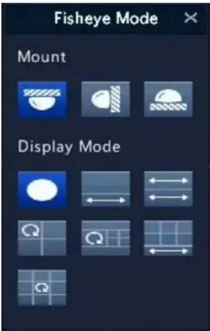
Three mounng modes are available: ceiling, wall, desktop. Ceiling and desktop mounng modes use the same dewarping method.
| Mounng Mode | Display Mode | Descripon |
| Ceiling mount |  | Original Image |
 | 360° Panoramic+1PTZ | |
| Desktop mount |  | 180° Panoramic |
 | Fisheye+3PTZ | |
 | Fisheye+4PTZ | |
 | 360° Panoramic+6PTZ | |
 | Fisheye+8PTZ | |
| Wall mount |  | Original Image |
 | Panoramic | |
 | Panoramic+3PTZ | |
 | Panoramic+4PTZ | |
 | Panoramic+8PTZ |
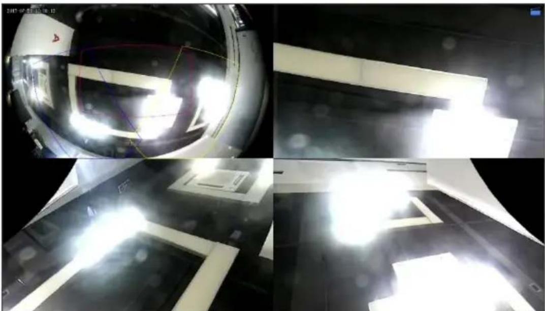
Operations: Take Ceiling Mount and Fisheye+3PTZ as an example:
natural_image
Interior view of a spacecraft with bright light beams reflecting the sky, showing no visible text or symbols.On a PTZ image, drag the mouse to rotate the image or use the scroll wheel to zoom in or out. A box appears on the sheye image as the image rotates, and as you drag the box or move the scroll wheel on the sheye image, the corresponding PTZ image rotates or zooms in or out as well.
Advanced Funcons
Upgrade connected IP cameras or restore factory default sengs for cameras under Camera > Camera > Advanced.
Click Check to see if the version of the connected IP camera is up to date. You may upgrade cameras by cloud ( ) or by disk ( ) one by one, or select mulple cameras and then click Upgrade by Cloud or By Disk to upgrade cameras in batches.
OSD Conguraon
On Screen Display (OSD) are characters displayed with video images on the screen, for example, camera name, date and me.
- Click Camera > OSD.
- Select the desired camera and then enter a camera name you want to display on the screen.
- Select date and me formats. Choose to display me, camera name and people counting result as needed.
- Set font size and color as needed.
- Drag the OSD to the desired posion in the preview window on the le.
- (Oponal) Click Copy to apply the same sengs to other cameras.
- Click Apply to save the sengs.
Image Conguraon
- Click Camera > Image.
- Select the desired camera and scene.
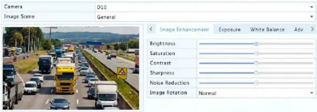
- Adjust sengs on the tabs as needed to achieve opmal images. See the following seconds for detailed informaon.

NOTE!
- A scene can be selected only when supported by the IP camera.
- To restore default image sengs, click Default in the lower right corner. This funcon is available only when the camera is connected to the NVR via the private protocol.
- Image sengs apply to both live and recorded videos.
Image enhancement
- Click the Image Enhancement tab.
- Adjust the sengs as needed. Some important parameters are described in the table below.
| Parameter | Descripon |
| Brightness | The greater the value, the brighter the images appear. |
| Saturaon | The amount of color in a specied hue. |
| Contrast | The degree of dience between the lightest (white) and darkest (black) parts of an image. Seng a greater value increases contrast. |
| Hue | Purity of colors in an image. |
| Sharpness | Contrast of boundaries of objects in an image. |
| Noise Reducon | Reduce noises in images to improve image quality. |
| Image Rotaon | Normal: Displays images without rotaon.Flip Vercal: Displays images ipped vercally.Flip Horizontal: Displays images ipped horizontally.180°: Displays images ipped vercally and horizontally.90° CW and 90° CCW: Display images in corridor format. The camera must be installed correctly (rotated 90° clockwise or counterclockwise). |
Exposure
1. Click the Exposure tab.

2. Adjust the sengs as needed. Some important parameters are described in the table below.
| Parameter | Descripon |
| Exposure Mode | Select the correct exposure mode to achieve the desired exposure eect. |
| Shuer(s) | Shuer is used to control the light that comes into the lens. A fast shuer speed is ideal for scenes in quick moon. A slow shuer speed is ideal for scenes that change slowly. |
| Gain(dB) | Control image signals so that the camera can output standard video signals in dierent light condions. |
| Iris | Adjust iris opening of the lens to control the amount of incoming light. |
| Slow Shuer | Improves image brightness in low light condions. |
| Slowest Shuer | Set the slowest shuer speed for the camera during exposure. |
| Compensaon | Adjust the compensaon value as required to achieve the desired image eects. |
| Day/Night Mode | • Automac: In this mode, the camera can automacally switch between night mode and day mode according to the ambient lighng condion to output opmum images.Night: The camera outputs high-quality black and white images according to the ambient lighng condion.Day: The camera outputs high-quality color images according to the ambient lighng condion. |
| Day/Night Sensitivity | Light threshold for switching between day mode and night mode. A higher sensitivity value means that the camera is more sensitive to the change of light and is therefore more easily to switch between day mode and night mode. |
| Day/Night Switching(s) | Set the length of me before the camera switches between day mode and night mode aer the switching conditions are met. |
| WDR | Enable WDR to ensure clear images in high contrast conditions. |
| WDR Level | Aer enabling WDR, you can improve image quality by adjusting the WDR level. |
White balance
- Click the White Balance tab.

- Adjust the sengs on this tab. Some important parameters are described in the table below.
| Parameter | Descripon |
| White Balance | Adjust the red or blue oset of the image:• Auto: The camera adjusts the red or blue oset automacally according to the lighng condion (the color tends to be blue).• Finetune: Allow you to adjust the red or blue oset manually. |
| Red Oset | Adjust the red oset manually. |
| Blue Oset | Adjust the blue oset manually. |
Advanced sengs
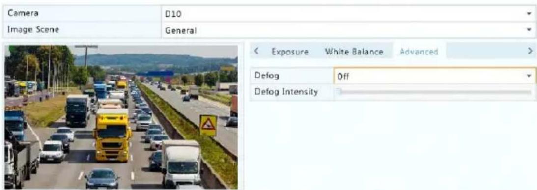
- Click the Advanced tab.
- Use defog to improve image quality in foggy days.
Privacy Mask Conguraon
A privacy mask is an area of solid color covering certain parts of the monitored area. Privacy mask protects specied areas of images from being viewed and recorded. Mulple mask areas are allowed.
- Click Camera > Privacy Mask.
- Select the desired camera, select Enable Privacy Mask, and then use the mouse to specify areas to mask. Up to four areas are allowed. The areas are dierenated by dierent colors.
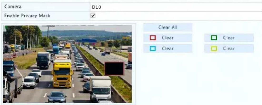
- (Oponal) To clear a mask area, click the corresponding Clear buon.
- Click Apply to save the sengs.
5 PTZ Control
PTZ (pan, It and zoom) control is applicable to PTZ cameras only and may vary depending on the funcons and protocols supported by the PTZ cameras. Refer to PTZ camera specicaons for more details.
PTZ Control Window and PTZ Management Window
- Click 🎨 on the window toolbar. The PTZ Control window appears. See PTZ Control Window Buons for detailed descripons.
- Click the Set buon. The PTZ Management window appears (can also be opened by clicking Camera > PTZ).
Table 5-1 PTZ Control Window Buons
| Buon | Descripon | |
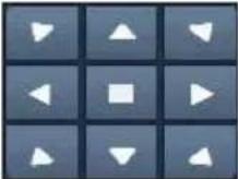 | Control the rotaon direcon of the PTZ camera or stop rotaon. | |
| Buon | Descripon |
 | Adjust the zoom, focus, and iris of the PTZ camera.Note: You can also zoom in or out using the scroll wheel on your mouse. |
 | Control the rotaon speed of the camera. 1 means the slowest, and 9 means the fastest. |
 | Click to display the PTZ Management window. |
 | Turn on/o the light.Turn on/o the wiper.Use 3D posioning.Turn on/o the heater.Turn on/o the funcon to remove snow.Turn on/o PTZ shortcut operaons.Note:Check that the 3D posioning, heater and snow removal funcons are supported by the camera before using.Use 3D posioning to zoom in or out.Dragging from top down zooms in. Dragging the other way zooms out. |
| [XYZT] | Preset buon. |
 | Save the current posion and status of the camera as a preset.Call a preset so the PTZ camera goes to the preset posion.Delete a presetNote: and are displayed for saved presets only. |
 | Preset patrol, recorded patrol and auto guard. For detailed informaon, see Seng a Preset Patrol,Seng a Recorded Patrol, and Seng Auto Guard. |
 | Start or stop. |
Seng and Calling a Preset
A preset posion (preset for short), is a saved view used to quickly steer the PTZ camera to a specific posion. A preset consists of the following sengs: pan and lt posions, zoom, focus, and iris.
- Access the PTZ Management window. For the detailed steps, see PTZ Control Window and PTZ Management Window.
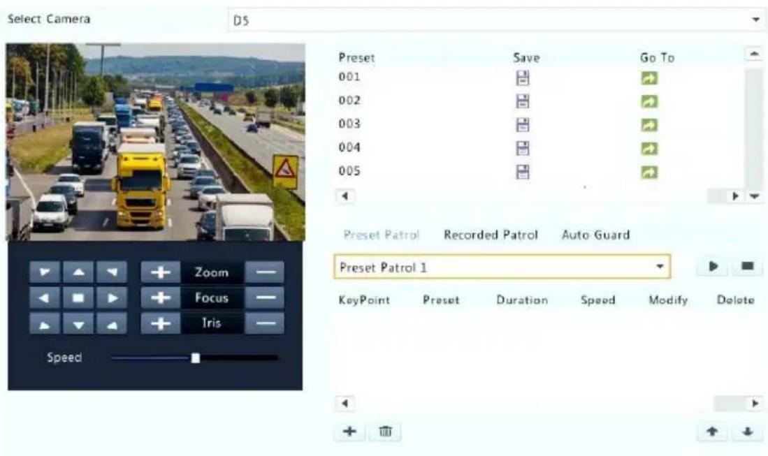
- Add presets.
a. Click the direconal buons to steer the PTZ camera to the desired posion.
b. Adjust the zoom, focus, and iris as needed.
c. Select a preset number not in use, and then click under Save.
d. Repeat the above steps to add all the presets.
- To call a preset, click → for the corresponding number. The camera rotates to the preset posion.
Presets can also be triggered by alarms. See Alarm-Triggered Acons for details.
Seng a Preset Patrol
Set the PTZ camera to patrol by presets (go from one preset to the next in specied order). You need to set presets rst and then select some as keypoints. Up to four patrol routes (Preset Patrol 1, 2, 3 and 4) are allowed for each PTZ camera, and each patrol route can have up to eight presets (keypoints). Aer seng presets, follow the steps to set a preset patrol. The following takes preset patrol 1 as an example.
- In the PTZ Management window, click + . A window is displayed as follows.
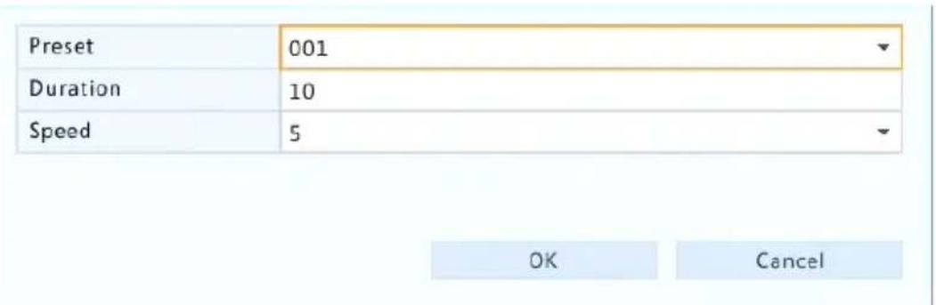
- Select a preset from the drop-down list, set the duraon (me the camera stays at the preset, unit: second), and then set the rotaon speed (1: slowest, 9: fastest). Click OK to save the sengs. The preset is added as a keypoint, as shown in the gure below.
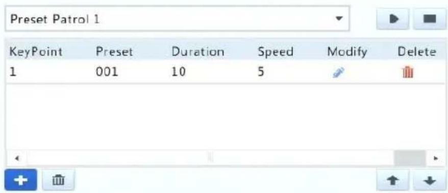
-
Repeat the above steps to add all presets (keypoints), and adjust the sequence of these presets by clicking or . Modify or delete a preset by clicking or . Clicking will delete all the added keypoints.
-
Aer completing the conguraon, click Apply to save the sengs. Now keypoints for preset patrol 1 is complete.
-
Click right to the drop-down list to start preset patrol 1. To stop, click

NOTE!
The duraon ranges from 0 to 1800 seconds (default: 10). The rotaon speed ranges from 1 to 9 levels (default: 5).
Seng a Recorded Patrol
This funcon requires the camera's support. The drop-down list and the buons on the right are hidden if this funcon is not supported by the camera. Currently only one recorded patrol route is allowed.
Record a patrol, including the patrol route, the me that the camera stays at a certain direcon, rotaon speed, zoom, focus and focus.
- Click ● to start recording. Steer the camera to the desired direcons, adjust the zoom, focus, iris as needed during the process.

-
Click ■ to stop recording. All the patrol acons have been recorded.
-
To start the recorded patrol, click . Click to stop.
Seng Auto Guard
Use auto guard so the PTZ camera automacally operates as congured if no operaon is performed by any user during a certain me period. Auto guard avoids situaons where the camera is le to monitor incorrect scenes by user's negligence.
This funcon requires the camera's support. The Auto Guard tab is hidden if it is not supported.
-
Click Auto Guard and then select Enable.
-
Select the desired mode from the drop-down list and then complete other sengs accordingly. Click Apply to save the sengs.
| Enable | ✓ |
| Idle State(s) | 60 |
| Mode | Preset Patrol |
| Route | Preset Patrol 1 |
6 Recording and Snapshot
Video recording has dierent levels of priority, which from high to low is: event recording, manual recording, and scheduled recording.
Encoding Sengs
Recording
The parameters and opons displayed may vary with camera model and version. Some funcons may be unavailable if the camera version is too low. In this case, you need to upgrade the camera rst.
1. Click Camera > Encoding.
| Select Camera | D1(IP Camera 19) | ||
| Storage Mode | Main Stream | ||
| Capture Mode | 2560*1440@25 | ||
| Stream Type | Normal | Sub Stream | |
| Video Compression | H265 | H264 | |
| Resolution | 2560^1440 | 1280*720(720P) | |
| Bitrate Type | CBR | CBR | |
| Bit Rate(Kbps) | 1536 | 1024 | |
| Range | 128~16384(Kbps) | 128~16384(Kbps) | |
| Frame Rate(fps) | 10 | 12 | |
| Image Quality | Highest | Highest | |
| I Frame Interval | 50 | 24 | |
| I Frame Range | 10~250 | 10~250 | |
| Smoothing | |||
| Audio Stream | |||
| U-Code | Off | Off | |
- Select the camera and then edit sengs as needed. Some parameters are described in the table below.
Table 6-1 Encoding Sengs
| Parameter | Descripon |
| Storage Mode | Main StreamSub StreamBy default, the main stream is used for storage. |
| Capture Mode | Combinaons of resoluons and frame rates.Note:This parameter is eecve only when the camerais connected to the NVR via the private protocol. |
| Stream Type | Normal: main stream that is intended for scheduled recording.Event: main stream that is intended for recording triggered by events such as alarm inputs or moon detecon alarms.Sub Stream: low resoluon video that is intended for local or remote real-me monitoring. |
| Video Compression | Video compression standard, for example, H.264, H.265.The listed opons depend on the standards supported by the camera. |
| Resoluon | Image resoluon. |
| Bitrate Type | CBR: Constant Bit Rate (CBR) is used to maintain a specific bit rate by varying the quality of video streams. CBR is preferred when limited bandwidth is available. The disadvantage is that video quality will vary and may decrease significantly with increased moon in the scene.VBR: When using Variable Bit Rate(VBR), video quality is kept as constant as possible, at the cost of a varying bit rate, and regardless of whether or not there is moon in the image. VBR is ideal when high quality is a requirement, especially when there is moon in the picture. |
| Bit Rate(Kbps) | Number of bits transferred per second. Select a value or selectCustomand then set a value as needed. |
| Range | Bit rate range. Currently the range is xed. |
| Frame Rate(fps) | Number of frames per second. |
| Image Quality | This parameter is eecve only whenBitrate Typeis set toVBR. 9 levels are provided. |
| I Frame Interval | Number of frames between two adjacent I frames. |
| I Frame Range | Range of I frames. Currently the range is xed. |
| Smoothing | Use the slider to control the sudden increase of bit rate. |
| Audio Stream | Enable or disable audio stream. |
| U-Code | The advanced mode achieves higher compression raos. |
-
(Oponal) Click Copy to apply some current sengs such as bit rate and frame rate to other cameras.
-
Click Apply to save the sengs.
Snapshot
Set resoluon, image quality and snapshot interval for snapshots taken according to schedule or triggered by an event.
- Click Camera > Snapshot.
- Set the parameters as needed.
| Select Camera | D1(IP Camera 19) | |
| Snapshot Type | Schedule | Event |
| Resolution | 704*576(4CIF) | 704*576(4CIF) |
| Image Quality | Medium | High |
| Snapshot Interval | 5s | 2s |

NOTE!
- Scheduled snapshot uses the Normal type of schedule. Event-triggered snapshot is triggered by an event such as an alarm input and a moon detecon alarm. Sengs eecve to event-triggered snapshot also apply to manual snapshot.
-
Snapshot interval is the length of me between two snapshots.
-
Click Apply to save the sengs.
Draw or Edit a Schedule
Make a recording or snapshot schedule by drawing (pressing and dragging) or by eding (using the Edit buon). The operaons for recording and snapshot are similar, so this secon only describes how to make a recording schedule.
- Click Storage > Recording.
- Select the camera from the list. Schedule is enabled by default. If it is disabled, select to enable it.
- Set Pre-Record and Post-Record as needed.
- (Applicable to some NVR models) To save a redundant copy of recordings, select Enable Redundant Recording and congregate a redundant hard disk (see Disk Management for details).
| Camera | D1 |
| Enable Schedule | ✓ |
| Pre-Record(sec) | 10 |
| Post-Record(sec) | 60 |
| Enable Redundant Recording | ☐ |

(Note: Click a color on the right and then draw the schedule.)
Copy
Exit
- Click a color icon on the right under the Edit buon and then draw a schedule on the le. You may also click Edit and set schedule details in the Edit Schedule window.

NOTE!
When eding a schedule, you may clear the All Day check box and set up to eight dierent periods for each day. To apply the sengs to other day(s), select the day(s) right to Copy To.
- Click Apply.
- (Oponal) Click Copy to apply the same sengs to other cameras.
Scheduled Recording and Snapshot
Scheduled Recording
Scheduled recording records video according to the set schedule and it is dierent from manual recording and alarm-triggered recording. A 24×7 recording schedule is enabled by default and may be edited as needed to record video in specied periods only.
See Draw or Edit a Schedule for the detailed steps. Make sure the schedule type is Normal. The set schedule appears in blue, which stands for scheduled recording.
Scheduled Snapshot
Congure scheduled snapshot under Storage > Snapshot. Scheduled snapshot is similar to scheduled recording (see Scheduled Recording for details). Make sure the schedule type is Normal.
Moon Detecon Recording and Snapshot
When enabled, a moon detecon alarm occurs if an object inside the detecon area moves to a certain extent (see Moon Detecon for more details). Moon detecon alarms can trigger acons including recording and snapshot.
Moon Detecon Recording
-
Click Alarm > Moon.
-
Select the camera from the list, and then select the check box to enable moon detecon.

NOTE!
- Moon detecon is enabled on the NVR by default. Unless modified, the detecon area covers the full screen, and recording is triggered only for the current camera. The sengs remain if you disable moon detecon and then enable it.
-
An alarm icon appears in the upper right corner when moon is detected.
-
In the preview window on the le side, click and drag your mouse to specify a moon detecon area (red grid). Use the sliders to adjust detecon sensitivity, target object size, and duraon.

-
Congure moon detecon recording: click right to Trigger Acons, click the Recording tab, select the desired camera, and then click OK.
-
(Oponal) Congure an arming schedule (me when acons will be triggered): click right to Arming Schedule and then set me periods as needed.
-
Set a recording schedule under Storage > Recording. For the detailed steps, see Draw or Edit a Schedule. Make sure the schedule type is Moon. The set schedule appears in green, which stands for moon detecon recording. The following gure shows an example.

bar
| Day | Value | |---|---| | Mon | 0 | | Tue | 3 | | Wed | 6 | | Thu | 9 | | Fri | 12 | | Sat | 15 | | Sun | 18 | | Holiday | 21 | | Mon | 24 |Moon Detecon Snapshot
Moon detecon snapshot is similar to moon detecon recording. You need to enable and conjure moon detecon alarm rst (see steps 1 to 3 in Moon Detecon Recording for details), and then proceed with the following steps.
- Set moon detecon snapshot under Alarm > Moon: click right to Trigger Acons. In the window displayed, click the Snapshot tab, select the desired camera, and then click OK.

- Set a snapshot schedule under Storage > Snapshot. For the detailed steps, see Draw or Edit a Schedule. Make sure the schedule type is Moon.
Alarm Triggered Recording and Snapshot
Set input alarms to trigger recording and snapshot. See Alarm Input and Output for more details.
Alarm Triggered Recording
- Click Alarm > Input/Output > Alarm Input.
- Set alarm input: click ✅ for the desired camera. In the window displayed, select Enable, select N.O. (normally open) or N.C. (normally closed) trigger mode, and then click OK.
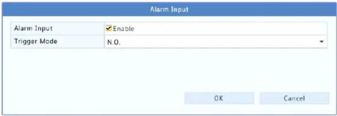

NOTE!
To apply the same sengs to other camera(s), click Copy and then select the desired camera(s).
- Set alarm triggered recording: click 🙏 under Trigger Acons. In the window displayed, click the Recording tab, select the desired camera, and then click OK.
- Set a schedule under Storage > Recording. For the detailed steps, see Draw or Edit a Schedule. Make sure the schedule type is Alarm. The set schedule appears in red, which stands for alarm-triggered recording. The following shows an example.

bar
| Day | Value | |---|---| | Mon | 0 | | Tue | 3 | | Wed | 6 | | Thu | 9 | | Fri | 12 | | Sat | 15 | | Sun | 18 | | Holiday | 21 | | Mon | 24 |Alarm Triggered Snapshot
Alarm triggered snapshot is similar to alarm triggered recording. You need to enable and congregate alarm input rst (see steps 1 to 2 in Alarm Triggered Recording for details) and then proceed with the following steps.
-
Set alarm triggered snapshot: Click ⚙ under Trigger Acons. In the window displayed, click the Snapshot tab, select the desired camera, and then click OK.
-
Set a snapshot schedule under Storage > Snapshot. For the detailed steps, see Draw or Edit a Schedule. Make sure the schedule type is Alarm.
Manual Recording and Snapshot
Manual Recording
Record video manually by clicking on the window toolbar. Alternatively, click Manual > Recording, select the desired camera and then click Start. To stop manual recording, click the window toolbar, or select the camera and then click Stop under Manual > Recording.

Manual Snapshot
Manual snapshot is similar to manual recording. Click Manual > Snapshot, select the desired camera, and then click Start. Click Stop to stop.
Holiday Recording and Snapshot
Holiday recording and snapshot allows you to specify certain me periods as holidays for scheduled recording and snapshot. First you specify certain date(s) as holidays, and then congure recording or snapshot schedules on these days.
Holiday Recording
- Click System > Holiday.
- Click the Add buon in the lower right corner. The Holiday window is displayed. Complete the sengs including the holiday name, start and end dates. By default a holiday is enabled when added and does not repeat.
| Holiday Name | NEW YEARS DAY | ||
| Status | ✓ Enable | □ Disable | |
| Repeat | No | ✓ Yes | |
| Mode | ✓ By Day | □ By Week | |
| Start Date | 01 | 01 | |
| End Date | 01 | 01 | |
- Click OK. The holiday appears in the list.
- Click Storage > Recording and then set a recording schedule as described in Draw or Edit a Schedule. Make sure Holiday is selected
in the Select Day drop-down list. In the following example, moon detecon recording is enabled on the set holiday.
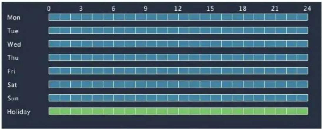
heatmap
| Day | 0 | 3 | 6 | 9 | 12 | 15 | 18 | 21 | 24 | |---|---|---|---|---|---|---|---|---|---| | Mon | Low | High | High | High | High | High | High | High | High | | Tue | Low | High | High | High | High | High | High | High | High | | Wed | Low | High | High | High | High | High | High | High | High | | Thu | Low | High | High | High | High | High | High | High | High | | Fri | Low | High | High | High | High | High | High | High | High | | Sat | Low | High | High | High | High | High | High | High | High | | Sun | Low | High | High | High | High | High | High | High | High | | Holiday | Low | Low | Low | Low | Low | Low | Low | Low | Low |Holiday Snapshot
Holiday snapshot is similar to holiday recording. First you set holidays under System > Holiday, and then congregate a snapshot schedule under Storage > Snapshot. Set a snapshot schedule as described in Scheduled Recording. Make sure Holiday is selected from the Select Day dropdown list.
Other Recording and Snapshot Types
Other recording and snapshot types:
- Event: Including the types below and VCA. Any of these types will trigger event recording/snapshot.
- Moon detecon AND alarm triggered (M and A for short): recording or snapshot is triggered only when a moon detecon alarm AND an input alarm occur simultaneously.
- Moon detecon OR alarm triggered (M or A for short): recording or snapshot is triggered when a moon detecon alarm OR an input alarm occurs.
When you choose an Event type of recording or snapshot, make sure you have enabled the corresponding alarm funcon and congured
alarm-triggered recording/snapshot. The conguraon steps are similar.
See Moon Detecon Recording and Snapshot for more details.
7 Playback
Instant Playback
Instant playback plays the video recorded during the last 5 minutes and 30 seconds. If no recording is found, it means there is no recording during this period.
- Click the desired window, and then click 📋 on the toolbar to start instant playback.
- You may drag the slider to control the progress. Pause and resume as needed.

natural_image
Highway traffic scene with multiple yellow trucks driving, no visible text or signagePlayback Toolbar
Table 7-1 Playback Toolbar Buons
| Buon | Descripon | |
 | Show playback progress.Note:A small window displaying video of the selected window is displayed as you drag the | |
| slider, helping locate the part of the video you want to view.The rst progress bar indicates playback progress of the video playing in the highlighted window. The second indicates the overall playback progress for all the selected cameras. | ||
 | Timeline. | |
 | Zoom in or out on the meline.Note: Alternatively, scroll your mouse wheel. | |
 | Play, pause, stop, and reverse. | |
 | Rewind or forward 30 seconds. | |
 | Slow down or speed up.Note: Clickto restore the normal playback speed aer clicking ,andvice versa. | |
 | Forward by frame. | |
 | Start or stop clipping video. | |
 | Take a snapshot. The window borders will ash white. | |
 | Lock. | |
 | Add a default or custom tag. | |
 | Manage les (clips, snapshots, locked les, tags). | |
 | Zoom in on images. For more details, seeZoom. | |
 | Enable/disable POS (available to certain NVR models).When enabled, POS OSD appears on the screen, and some toolbar buons are deactivated.These buons only appear in two playback modes: playback by camera and data and playback by POS.POS OSD duraon (how long POS OSD appears on screen) varies with playback mode. For playback by camera and date, the duraon is xed to 5 seconds.For playback by POS, the duraon is congorable.SeePlayback by Camera and Date and Playback by | |
| POS for more details. | ||
 | Turn o/on audio. | |
 | Adjust sound volume for the current window. | |
Playback by Camera and Date
Use this method to play recordings found by camera and date.
- Right-click the mouse and then choose Playback.
- Select the desired camera. By clicking Max. Cameras in the upper right corner you will select the maximum number of cameras allowed.

NOTE!
You can select mulple cameras for synchronous playback. Clicking Max. Camera selects the maximum number of cameras allowed, and clicking Close All stops playback for all cameras. The performance varies with NVR model.
- Select the desired date on the calendar and then click ▶ to start playback. Double-clicking the date will start playback directly.

NOTE!
- The calendar uses different ags to indicate dierent recording types. No ag means no recording. The blue ag means normal recording. The red ag means event-triggered recording.
- In the drop-down list right to playback mode: High Denion means video recorded with the main or sub stream; Standard Denion means video recorded with the third stream.
Playback in Corridor Mode
Play recordings in corridor mode in mulple windows.
- In the playback window, select Corridor from the drop-down list in the upper le corner.
- Select cameras and then double-click the desired date to start playback.
Playback by Tag
Add tags named with keywords such as event name and locaon to a recording and use tags to quickly locate the part of the video you need during playback.
Adding a Tag
- Right-click and then click choose Playback.
- Click to add a default tag named TAG. To add a custom tag, click and then set the tag name, for example, tag1.
- To manage the added tags, click 📄, and then rename or delete tags as needed.
| Camera | Name | Time | Edit | Delete |
| D14 | TAG | 2016-04-15 00:01:16 | ||
| D14 | TAG | 2016-04-15 04:57:29 | ||
| D14 | Tag1 | 2016-04-15 05:49:38 |
Playback by Tag
-
In the playback window, select Tag from the drop-down list in the upper le corner.
-
Select cameras, set the me period, enter keywords, and then click Search. Search results, if there are any, are displayed with names of cameras and tags.
-
Click ▶ for the desired tag to start playback. You may use the Start Before and Stop Aer drop-down lists to set when the tagged video starts and ends.
Playback by Event
Specify an event type and search for and play videos recorded for one or more cameras during a specied me period.
- In the playback window, select Event from the drop-down list in the upper le corner.
- Select the desired event type, for example, motion.
- Select the desired camera, set the me period, and then click Search.
- Click for the desired recording to start playback.
Playback by Smart Search
This funcon provides an ecient way to review recordings containing smart search results such as detected moons. In smart playback mode, the system analyzes recordings for smart search results. If such results are detected, the progress bar is highlighted in green, and the video plays at the normal speed, allowing you enough me to catch details; otherwise, the video plays at 16x speed to save me.
- In the playback window, select Smart from the drop-down list in the upper le corner.
- Click for the desired camera to start smart playback.
- Click 📋. The smart search window is displayed. By default, the full screen is the smart search area. To clear all, click ; to restore the full-screen search area, click 📋
-
Set smart search rules, including detecon area and sensitivity.
-
Click to start search. To quit, click .
Playback by External File
Use this funcon to play recordings stored in an external storage device, for example, a USB drive or a portable USB hard drive.
- In the playback window, select External File from the drop-down list in the upper le corner.
- Click Refresh and then wait for the NVR to read the external storage device.
- Select the desired recording le and then click to start playback.
Playback by Image
Specify an image type (for example, Normal or Moon) to search for and play images from one or more cameras during a specied me period.
- In the playback window, select Image from the drop-down list in the upper le corner.
- Select a type from the Type drop-down list in the upper right corner.
- Select the desired camera(s), set the desired me period, and then click Search.
- Click the desired le to start playback.
Playback by POS
Use this funcon to play recordings of a POS machine.
- In the playback window, select POS from the drop-down list in the upper le corner.
- Select the desired camera, set the me period, enter keywords and then click Search.

NOTE!
Keywords allow special characters & (means AND) and | (means OR).
-
Click to display overlay content.
-
Click to start playback.
File Management
File management allows you to manage video clips, tags, snapshots taken during playback, and lock or unlock les.
- Take snapshot during playback.
a. Click in the playback window to take a snapshot of the desired image.
b. Click 📋 and then click the Playback Image tab to view the snapshot.
c. Select the desired image le(s) and then click Backup to save them to the storage device.

NOTE!
The image resoluon depends on the resoluon from the output interface and the number of windows displayed when the snapshot taken.
- Lock les.
Use this funcon to lock a recording le so it will not be overwrien.
a. Click 🔒 for the recording you want to lock in the playback window.
b. Click 📄 and then click the Locked File tab to view the locked le. To unlock a le, click 🔍, and the icon changes to .To back up a le, select the le and then click Backup.
Recording Backup
Backup, also known as recording backup, is the process of querying video stored on a hard disk of the NVR and then saving to a USB storage device or a DVD-R disc as a le.
Recording backup has the following conditions:
- Back up using a USB storage device: format the paron in FAT32 or NTFS format; connect the storage device correctly to the NVR.
- Back up using a disc: use a GP65NB60 DVD burner. Make sure the DVD-R disc is empty, and the burner is correctly connected to the NVR.
- Permission is required.
- The recording to back up is stored on a hard disk of the NVR.

NOTE!
- The default le format is .mp4 when you back up recordings to a USB storage device.
- When backing up using a disc, recordings are saved as .TS les only.
Normal Backup
- Click Backup > Recording. All cameras are selected by default.
- Set search conditions and then click Search. Search results are displayed.

NOTE!
You can lock/unlock and play recording les in this window.
-
Select the desired recording(s) and then click Backup.
-
Select a paron.
- Back up to USB storage device
Set the desnaon in the USB storage device and then click Backup. The recording(s) will be saved to the specied directory.

NOTE!
- You may want to create a new folder for the recording(s) by clicking New Folder.
- If the connected storage device has a capacity that is greater than 2T, clicking Format will format the device to NTFS le system; if the capacity is 2T or less, the device will be formed to FAT32 or NTFS. Only certain devices can format a storage device that has a greater capacity than 2T.
- A progress bar (e.g., Exporng X/Y) is displayed to indicate the progress, where X indicates the current number being backed up, and Y indicates the total number of recordings. To cancel the operaon, click Cancel.
- A backup le is named in this format: camera name-recording start me.le extension. For example, Ch9-20150630183546.mp4.
- Back up to a DVD-R disc
Set the desnaon and then click Backup. The recording(s) will be saved to the specied directory.

NOTE!
- Before you start burning, check that the video to back up was not compressed using U-Code.
- Clicking Cancel before burning is nished will cause the disc unusable.
- When burning is nished, wait for the drive to eject itself. Do not eject the drive manually.
- The NVR does not support playback of recordings saved on a disc.
Video Clip Backup
A recording can be clipped and saved to a USB storage device.
- Open the playback window. For the detailed steps, see Playback.
- Aer playback starts, click and on the playback toolbar to clip videos.
- Click 📋 and then click the Video Clip tab to view video clips.
- Select the desired video clip(s) and then click Backup.
- Select a desnaon in the USB storage device and then click Backup. The selected video clips are saved to the specied directory.
Image Backup
The default format of image backup is JPG.
- Click Backup > Image.
- Set search conditions and then click Search. Search results are displayed.

NOTE!
The image resoluon depends on the resoluon from the output interface and the number of windows displayed when the snapshot taken.
- Select the desired le(s) and then click Backup.
- Select a desnaon in the USB storage device and then click Backup. The selected les are saved to the specied directory.
9 Alarm
Alarm Input and Output
Alarm Input
-
Click Alarm > Input/Output > Alarm Input.
-
Click for the desired camera. In the Alarm Input window, select Enable to enable alarm input.
- Select the normally open (N.O.) or normally closed (N.C.) trigger mode, and then click OK.
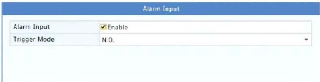
- Click ✿ under Trigger Acons and then set acon(s) to trigger. For more details, see Alarm-Triggered Acons.
| Buzzer | ||||||||
| Send Email | ||||||||
| Pop-up Window | ||||||||
| Recording | Preset | Preview | Alarm Output | Snapshot | ||||
| All | D1 | D2 | D3 | D4 | D5 | D6 | D7 | D8 |
| D9 | D10 | D11 | D12 | D13 | ✓D14 | D15 | D16 | |

NOTE!
- The number of cameras that can be connected may vary with NVR model.
-
Acons that can be triggered may vary with alarm type.
-
Click ⚙️ under Arming Schedule and then set the me when acons will be triggered.
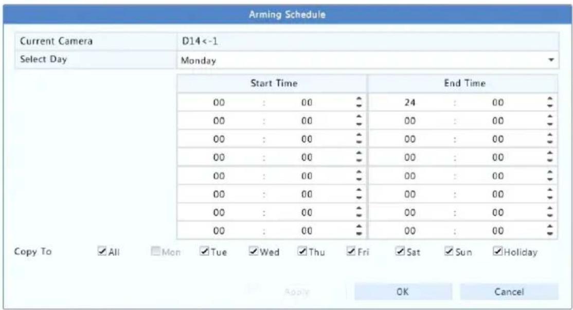

NOTE!
- The default schedule is 24×7. You may change it as needed and set up to eight dierent periods for each day. Time periods cannot overlap.
- To apply the same arming schedule to other days, select the intended days right to Copy To.
- To apply the same sengs to other cameras, click Copy, select cameras, and then click OK.
Alarm Output
- Click Alarm > Input/Output > Alarm Output.
- Click ✪ under Edit for the desired camera, and then set the default status and duraon. Aer you have completed the sengs, click OK.
- Click ⚙ under Arming Schedule and then set the me when acons will be triggered.
To apply the same sengs to other cameras, click Copy, select cameras, and then click OK.
Moon Detecon
When enabled, a moon detecon alarm occurs if an object inside the detecon area moves to certain extent, and an alarm icon appears in the upper right corner.
Moon detecon is enabled on the NVR by default. Unless modified, the detecon area covers the full screen, and recording is triggered only for the current camera. The sengs remain if you disable moon detecon and then enable it.
- Click Alarm > Moon.
- Select the desired camera and then select Enable to enable moon detecon.
- Use the mouse to draw a detecon area, and drag the slider to set detecon sensitivity, target object size, and duraon. The higher the sensitivity, the more likely a moving object will be detected.

- Click right to Trigger Acons and set acon(s) to trigger. For more details, see Alarm-Triggered Acons.

NOTE!
- The number of cameras that can be connected may vary with NVR model.
-
Acons that can be triggered may vary with alarm type.
-
(Oponal) Click right to Arming Schedule and then set the me when acons will be triggered.

NOTE!
- The default schedule is 24×7. You may change it as needed and set up to eight dierent periods for each day. Time periods cannot overlap.
-
To apply the same arming schedule to other days, select the intended days right to Copy To.
-
Click Apply to save the sengs.
- (Oponal) Click Copy to apply the same sengs to other cameras.
Tampering Detecon
A tampering detecon alarm occurs when the camera lens is covered.
- Click Alarm >Tampering.
- Select the desired camera and then select Enable to enable tampering detecon.

(Note: By default, tampering detection is effective to the full screen.)
- Click right to Trigger Acons and set acon(s) to trigger. For more details, see Alarm-Triggered Acons.
- (Oponal) Click right to Arming Schedule and then set the me when acons will be triggered.
- (Oponal) Click Copy to apply the same sengs to other cameras.
- Click Apply to save the sengs.
Video Loss
A video loss alarm occurs when the NVR loses video signals from a camera. Video loss alarm is enabled by default.
-
Click Alarm > Video Loss. To disable video loss alarm for a channel, click , which then changes to .
-
Click 🙏 under Trigger Acons and set acon(s) to trigger. For more details, see Alarm-Triggered Acons.

NOTE!
Video loss alarm cannot trigger recording, preset, preview (live view) and snapshot acons for the current camera.
-
Click 🙏 under Arming Schedule and then set the me when acons will be triggered.
-
(Oponal) Click Copy to apply the same sengs to other cameras.
VCA
VCA refers to Video Content Analysis.
Basic Conguraon
Click Alarm > VCA. The Basic page is displayed. Select the camera and then select Save VCA Images if you want to use the VCA search funcon.
Face Detecon
Face detecon is used to detect human faces in specied a surveillance area.
- Click Alarm > VCA > Face Detecon.
Camera
Enable
Detect All Faces
D1
√
√

natural_image
Two people standing in front of a modern office space with large wall-mounted screens and green plants (no visible text or symbols)(Note: Faces smaller than the red rectangle cannot be detected. You can drag to move the rectangle.)
Trigger Actions
Arming Schedule
Sensitivity

Draw
- Click Alarm > VCA > Face Detecon.
- Select the camera and then select Enable. To detect all faces in the detecon area, select Detect All Faces.
- Click Draw and then draw a detecon area using the mouse. Adjust detecon sensitivity as needed to achieve opmal eects.
Intrusion Detecon
Intrusion detecon is used to detect objects entering specied area(s) and trigger acons as needed.
- Click Alarm > VCA > Intrusion Detecon.

- Select the camera and then select Enable to enable intrusion detecon.
- Draw detecon areas on the screen and set detecon rules including sensitivity, threshold and percentage. Up to four areas are allowed. The threshold means the minimum length of me an object stays in the detecon area(s). The percentage means the proportion of target object size to the size of the detecon area. An alarm occurs when the threshold or the percentage is exceeded.
- Click right to Trigger Acons and set acon(s) to trigger. For more details, see Alarm-Triggered Acons.
- (Oponal) Click right to Arming Schedule and then set the me when acons will be triggered.
- Click Apply to save the sengs.
Cross Line Detecon
Cross line detecon is used to detect whether any object crosses a virtual line on the screen and trigger alarms as needed.
- Click Alarm > VCA > Intrusion Detecon.

- Select the camera and then select Enable to enable cross line detecon.
- Draw detecon line(s). Up to four are allowed. Set detecon rules, including entrance direcon, sensitivity.
- Click right to Trigger Acons and set acon(s) to trigger. For more details, see Alarm-Triggered Acons.
- (Oponal) Click right to Arming Schedule and then set the me when acons will be triggered.
- Click Apply to save the sengs.
Audio Detecon
An audio detecon alarm occurs when a camera detects a sudden change in sound volume.
- Click Alarm > Audio Detecon.
- Select the camera and then select Enable to enable audio detecon.

- Click right to Trigger Acons and set acon(s) to trigger. For more details, see Alarm-Triggered Acons.
- (Oponal) Click right to Arming Schedule and then set the me when acons will be triggered.
- Select a detecon type and adjust the sengs as needed.
| Detecon Type | Descripon |
| Sudden Rise | An alarm occurs when the rise of volume exceeds the set value. |
| Sudden Fall | An alarm occurs when the fall of volume exceeds the set value. |
| Sudden Change | An alarm occurs when the rise or fall of volume exceeds the set value. |
| Threshold | An alarm occurs when the volume exceeds the set value. |
- Click Apply to save the sengs.
People Counng
People counng is used to count people entering or leaving an area. Only certain NVR models support this funcon. This funcon cannot be used at the same me with other VCA funcons (face detecon, intrusion detecon, cross line detecon, defocus detecon and scene change detecon).
- Click Alarm > People Counng.

- Select the camera and then select Enable Shoulder Demarcaon. Draw a virtual line on the screen to set the minimum width of detecon. People narrower than the set width will be ignored.
- Click the Draw buon and then draw rules on the le. Set entrance direcon and sensitivity as needed.
- By selecng Enable Clear by Schedule, you can have people counng OSD reset at a specied me every day. You may also click Clear Counng Result to clear the OSD immediately. Reseng people counng OSD only changes the OSD. It does not change report stascs.
- Click Apply to save the sengs.
Defocus Detecon
Use defocus detecon to check whether the camera focuses properly.
- Click Alarm > Defocus Detecon.
- Select the desired camera and then select Enable to enable defocus detecon.

- Click right to Trigger Acons and set acon(s) to trigger. For more details, see Alarm-Triggered Acons.
- (Oponal) Click right to Arming Schedule and then set the me when acons will be triggered.
- Set detecon sensitivity and then click Apply to save the sengs.
Scene Change Detecon
Use scene change detecon to detect the change of surveillance environment caused by external factors such as intenonal rotaon of the camera.
- Click Alarm > VCA > Scene Change Detecon.
- Select the desired camera and then select Enable to enable scene change detecon.

-
Click right to Trigger Acons and set acon(s) to trigger. For more details, see Alarm-Triggered Acons.
-
(Oponal) Click right to Arming Schedule and then set the me when acons will be triggered.
-
Set detecon sensitivity and then click Apply to save the sengs.
Auto Tracking
Auto tracking detects moving objects in the scene and automacally tracks the rst object detected.
- Click Alarm > VCA > Auto Tracking.
- Select the desired camera and then select Enable to enable auto tracking.

- Click right to Trigger Acons and set acon(s) to trigger. For more details, see Alarm-Triggered Acons.
- (Oponal) Click right to Arming Schedule and then set the me when acons will be triggered.
- Set tracking mode (currently only Panoramic). Set tracking meout and zoom rao.

NOTE!
- Tracking Timeout(s) means the maximum length of me the camera tracks an object automacally. The range is 1-300 seconds and the default is 30 seconds. When the tracking meout is over, the camera stops tracking and restores the original scene and status.
-
Zoom means zoom rao and includes Auto (default) and Current Zoom. Auto means the camera automacally adjusts the zoom rao according to the tracking distance and thus captures more details on the tracking object; Current Zoom means the camera maintains the original zoom rao during tracking and thus aends to the whole scene.
-
Click Apply to save the sengs.
Alert
The NVR reports an alert when an event occurs in the system. The following are some alerts and their denions in the system.
- Running Out of Space: Less than 10% of disk space remains.
• Space Used Up: No disk space. - Disk Oine: A disk is not properly connected or is damaged.
- Disk Abnormal: A disk can be detected but cannot be accessed.
- Illegal Access: A failed login aempt for a username that does not exist or a password that is incorrect.
• Network Disconnected: Network conneccon is lost.
• IP Conict: Devices on the network use the same IP address. - Recording/Snapshot Abnormal: Storage resource cannot be found, for example, when all hard disks are removed, or when there is no disk in disk group 1 (see Disk Group for more informaon).
Perform the following steps to congregate an alert:
- Click Alarm > Alert.
- Select an alert type, select the desired acons, and then select the camera(s) for which you want to enable alarm output.
| Alert Type | IP Conflict |
| Buzzer | ☐ |
| Send Email | ☐ |
| Pop-up Window | ☐ |
| Trigger Alarm Output | ☐All |
| Select | Alarm Output No. |
| ☐ | A->1 |
| ☐ | A->2 |
| ☐ | A->3 |
| ☐ | A->4 |
- Click Apply to save the sengs.
Buzzer
The buzzer can be triggered by alarms to alert the user. Follow the steps to set how long the buzzer will buzz aer it is triggered.
- Click Alarm > Buzzer.
| Alarm Duration | Maximum | Custom |
| Custom Duration(sec) | 1 | |
-
Set the duraon as needed. The range is from 1 to 600 seconds.
-
Click Apply to save the sengs.
Alarm-Triggered Acons
An alarm can trigger acons, for example, buzzer, recording, and preview. The supported acons may vary with NVR model.
Alarm-Triggered Buzzer
The NVR makes a buzzing sound when an alarm occurs.
Alarm-Triggered E-mail
The NVR e-mails an alarm message to a specied email address when an alarm occurs.
Alarm-Triggered Pop-up Window
A window pops up when an alarm occurs.
Alarm-Triggered Recording
The NVR records video from a specied camera when an alarm occurs.
Alarm-Triggered Snapshot
The NVR takes a snapshot when an alarm occurs.
Alarm-Triggered Preset
A PTZ camera rotates to a preset posion when an alarm occurs.
Alarm-Triggered Preview
The NVR plays live video in full screen when an alarm occurs.
Alarm-Triggered Alarm Output
The NVR outputs an alarm to trigger acons by a third-party device when an alarm occurs.
Manual Alarm
Manual Alarm Output
Follow the steps to trigger or clear an alarm output manually.
- Click Manual > Alarm > Manual Alarm.
- To trigger an alarm output manually, select the desired channel and then click Trigger. To clear an alarm output manually, select the desired channel and then click Clear.
Manual Buzzer
Follow the steps to stop the buzzer manually.
- Click Manual > Alarm > Buzzer.
- Select the buzzer (in Started status) and then click Stop.
10 VCA Search
VCA means Video Content Analysis. VCA search searches VCA data including behavior, human face, and people counng. Only certain NVR models support this funcon. You need to select Save VCA Images under Alarm > VCA before using behavior search and face search funcons.
Behavior Search
Use behavior search to search for recordings triggered by detected behaviors including cross line and intrusion.
-
Click VCA Search > Behavior.
-
Select camera(s), set a search period, select a search type, and then click Search. Search results are displayed.
- View search results in a chart or table. Back up search results (including images and recordings) as needed. To view videos recorded when the behavior was detected (around 10 seconds before and aer), click the play buon. The following gure shows an example.

Face Search
Use face search to search for recordings triggered by detected faces.
- Click VCA Search >Face.
- Select cameras, set a search period, and then click Search. Search results are displayed.
- View search results in a chart or table. Back up search results (including images and recordings) as needed. To view videos recorded when the face was detected (around 10 seconds before and aer), click the play buon. The following shows an example.
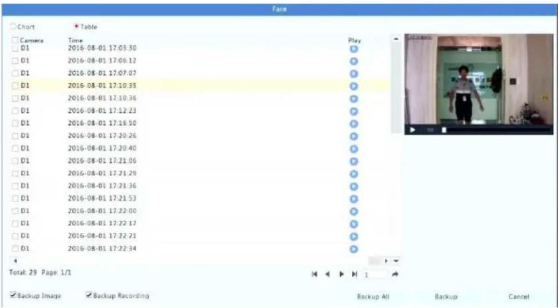
People Counng
Use people counting to count people entering and/or leaving an area during a specified period (day, week or year).
- Click VCA Search > Counng.
- Select the camera, counting type (people entered or le), report type (daily, weekly, monthly or yearly), set a me period, and then click Count. Search results are displayed. You may choose to display search results using a chart or table. When you click a bar, stascs of the selected camera(s) are displayed. The gure below shows an example.
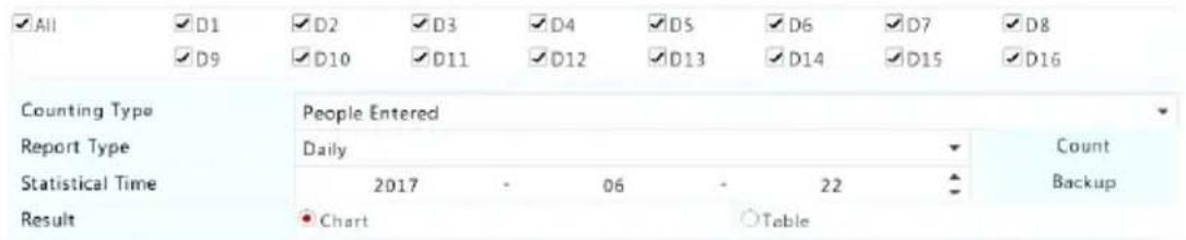

bar
| Hour | Entered (People(100)) | Left (People(100)) | |---|---|---| | 1 | 0.0 | 0.0 | | 2 | 0.0 | 0.0 | | 3 | 0.0 | 0.0 | | 4 | 0.0 | 0.0 | | 5 | 0.0 | 0.0 | | 6 | 0.0 | 0.0 | | 7 | 0.0 | 0.0 | | 8 | 0.0 | 0.0 | | 9 | 0.0 | 0.0 | | 10 | 0.2 | 0.0 | | 11 | 0.3 | 0.0 | | 12 | 0.7 | 0.0 | | 13 | 3.5 | 0.0 | | 14 | 1.1 | 0.0 | | 15 | 0.2 | 0.0 | | 16 | 0.5 | 0.0 | | 17 | 0.6 | 0.0 | | 18 | 0.8 | 0.0 | | 19 | 0.8 | 0.0 | | 20 | 0.2 | 0.0 | | 21 | 0.0 | 0.0 | | 22 | 0.0 | 0.0 | | 23 | 0.0 | 0.0 | | 24 | 0.0 | 0.0 | Hour- (Oponal) To save the counting stascs to a connected USB storage device, click Backup.
11 Network Conguraon
Network conguraon is required if your NVR operates in a network.

NOTE!
The default IP address is 192.168.1.30 for NIC 1 and 192.168.2.30 for NIC 2, and likewise.
TCP/IP
- Click System > Network > Basic.
- Set the network parameters as needed. DHCP is enabled by default. You can choose a working mode if your NVR has two NICs:
- Mul-address mode: The two NICs work independently and can be congured separately. Either NIC can be chosen as the default route, and data will be forwarded through this NIC when the NVR connects to the extranet.
- Load balance mode: The two NICs are bound to the same IP address and work together to share network trac.
- Net fault-tolerance mode: The two NICs are bound to the same IP address. In cases where one NIC fails, the other takes over service seamlessly from the faulty one to ensure network connectivity.
| Working Mode | Multi-address |
| Select NIC | NIC1 |
| Enable DHCP | |
| IPv4 Address | 206 .7 .102 .232 |
| IPv4 Subnet Mask | 255 .255 .0 .0 |
| IPv4 Default Gateway | 206 .7 .0 .1 |
| IPv6 Mode | Router Advertisement |
| IPv6 Address | |
| IPv6 Prefix Length | |
| IPv6 Default Gateway | |
| MAC Address | 48:ea:63:01:17:67 |
| MTU(Bytes) | 1500 |
| Preferred DNS Server | 8 .8 .8 .8 |
| Alternate DNS Server | 8 .8 .4 .4 |
| Default Route | NIC1 |
3. Click Apply to save the sengs.

NOTE!
- For an NVR with mulple NICs, you can congregate the NICs and choose a default route (currently NIC1).
- If your NVR has a PoE port or a switching port, you can congregate an internal NIC IPv4 address.

CAUTION!
- If you switch the working mode, the enabled 802.1x and ARP protecon will be disabled automacally.
- The valid MTU ranges from 576 to 1500 (1280-1500 for IPv6). To use IPv6, make sure the NVR and PC can connect to each other using IPv6 addresses. To view live or recorded videos, make sure the IPv4 addresses are also connectable.
PPPoE
The NVR allows access through Point-to-Point over Ethernet (PPPoE). If you are using 3G/4G (see 3G/4G for details), you need to disable it rst.
- Click System > Network > PPPoE.
- Enable PPPoE by selecng the check box.
- Enter the username and password provided by your Internet Service Provider (ISP). Network informaon including IP address appears when dial-up succeeds.

NOTE!
If your NVR has mulple NICs, PPPoE dial-up will be implemented through the NIC specied as the default route.
- Click Apply to save the sengs.
EZCloud
The NVR allows access from the cloud website (en.ezcloud.uniview.com) or from the mobile surveillance app (EZView). You need to sign up for a cloud account at en.ezcloud.uniview.com rst. Make sure the NVR is connected to the Internet.
- Click System > Network > EZCloud.
- EZCloud is enabled by default.
- To add the NVR to cloud at the cloud website: log in to your account at en.ezcloud.uniview.com and then add the NVR by entering the register code and device name.
- To add the NVR to cloud using the EZView: scan the QR code using your mobile phone to download the app. Install the app and then log in with your cloud account. Scan the QR code to add the NVR to cloud.
| Enable EZCloud | √ |
| Domain Name | en.ezcloud.uniview.com |
| Register Code | QWERTYUIOP0123456789ASDFG |
| Device Status | Online |
| Username | tw2357 |
| Device Name | ez |
| Service Agreement | http://ezcloud.uniview.com/doc/termsofservice.html |
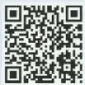
Delete
Apply
Exit

NOTE!
- You may access the NVR through cloud if the device status is Online. The username is your cloud account name, and the device name is the name you entered at the cloud website.
- If the device is oine, the possible causes will be displayed for your reference.
• To delete the NVR from cloud, click Delete.
5. Click Apply to save the sengs.
DDNS
If your NVR is connected to the Internet through PPPoE, the IP address of the network changes every me it connects to the ISP server without your awareness. This is inconvenient when you remotely access your NVR with an IP address. To avoid this issue, you can register with an DDNS server to obtain a domain name for your NVR and then access your NVR by vising the domain name instead of an IP address (hp://DDNS server address/NVR's domain name) using a web browser.
1. Click System > Network > DDNS.
- Enable DDNS, select a DDNS type, and then complete other sengs.
- If the DDNS type is DynDNS or No-IP, enter the domain name, username and password. The domain name is the one that you have successfully registered at a domain name registraon website (e.g., DynDNS). The username and password are those of the account you have registered at the domain name registraon website (e.g., DynDNS).
| Enable DDNS | √ |
| DDNS Type | DynDNS |
| Server Address | members.dyndns.org |
| Port | 80 |
| Domain Name | NVR.dyndns.com |
| Username | admin |
| Password | ***** |
| Confirm | ***** |
- If the DDNS type is EZDDNS, enter a valid domain name for your NVR and then click Test to see if the domain name is available.
| Enable DDNS | |
| DDNS Type | EZDDNS |
| Server Address | en.ezcloud.uniview.com |
| Port | 80 |
| Domain Name | 08 |
| Device Status | Online |
| Device Address | en.ezcloud.uniview.com/08 |
- Click Apply to save the sengs.
3G/4G
Connect the NVR to the Internet through 3G/4G wireless network conncon. Only certain NVR models support this funcon. PPPoE and 3G/4G cannot be used at the same me.
-
Click System > Network > 3G/4G.
-
Select Enable 3G/4G and then complete the sengs including network type, dial-up number, username and password.

- Click Apply to save the sengs.
Port
Normally the default port numbers need no modicaon. This funcon is mainly used together with the port mapping funcon. See Port Mapping for more details.
- Click System > Network > Port.
- Congure ports as planned. Each port number must be unique.
| HTTP Port | 80 |
| RTSP Port | 554 |
| HTTPS Port | 443 |
| rtsp://:/unicast/c/s/live | |
| RTSP URL Format | : 1-n |
| : 0(main stream) or 1(sub stream) |

NOTE!
- A valid port number ranges from 1 to 65535, among which 21, 23, 2000, 3702 and 60000 are reserved.
-
An RTSP URL can be used to view live video of a channel of the current NVR from another NVR. See Opon 5 in Adding an IP Device for more informaon.
-
Click Apply to save the sengs.
Port Mapping
Two port mapping methods are available:
• Universal Plug and Play (UPnP)
- Internal and external mapping
UPnP
UPnP enables the NVR to discover other devices on the network and establish network services such as data sharing and communicaon.
To use UPnP in your NVR, you must enable UPnP in the connected router. With UPnP enabled for Network Address Translaon (NAT), the ports on the NVR can be mapped automatically to the router, and computers can access your NVR from outside the LAN.
-
Click System > Network > Port Mapping.
-
UPnP is enabled by default. Select the desired mapping type from the drop-down list. To map ports manually, select Manual and then set external ports for the router.

NOTE!
- Automac mapping (Auto) is recommended. Ports will conict if not congured properly.
- For an NVR with mulple NICs, port mapping should be congured based on the NIC specied as the default route.
| Enable Port Mapping | ||||
| Mapping Mode | UPnP | Manual | ||
| UPnP Mapping | Auto | |||
| HTTP Port | 50554 | |||
| RTSP Port | 50818 | |||
| HTTPS Port | 57703 | |||
| Port Type | External IP Address | External Port | Internal Port | UPnP Status |
| HTTP Port | 0.0.0.0 | 50554 | 80 | Active |
| RTSP Port | N/A | 50818 | 554 | Inactive |
| HTTPS Port | N/A | 57703 | 443 | Inactive |
-
Click Refresh and check that Acve is displayed for these ports under UPnP Status.
-
Click Apply to save the sengs.
Manual Port Mapping
If your router does not support UPnP, then you need to congregate internal and external ports manually.

NOTE!
- The principle of port mapping is that the internal and external ports of the NVR are consistent with that of the router.
-
Some routers may require the same internal and external ports for the NVR and the router.
-
Click System > Network > Port Mapping.
- Select Manual for Mapping Mode, and then set external ports manually.
| Enable Port Mapping | √ | |
| Mapping Mode | ○UPnP | ●Manual |
| HTTP Port | 80 | |
| RTSP Port | 554 | |
| HTTPS Port | 443 |
- Click Apply to save the sengs.
NOTE!
Aer port mapping is completed, you may access the Web client of your NVR by entering the following informaon in the address bar of your web browser: router's WAN port IP address:external HTTP port. For example, if 10.2.2.10 is the IP address and 82 is the HTTP port, then you enter hp://10.2.2.10:82.
Aer Email is enabled as a triggered acon (in Trigger Acons windows) and congured properly, the NVR sends an email nocaon to specied email address(es) if an alarm occurs within the me period(s) set in the arming schedule. The email contains basic alarm informaon such as alarm type, alarm me, camera ID, and camera name, etc.
Before using this funcon, make sure the NVR has a functional conncon to an SMTP server with which you have a valid email account. Depending on the intended recipients, a conncon to the Internet may be required.
Only certain NVR models support this funcon.
- Click System > Network > Email.
- Congure the related parameters. If server authencaon is required, you need to enter the correct username and password. Click Test to send a test email.
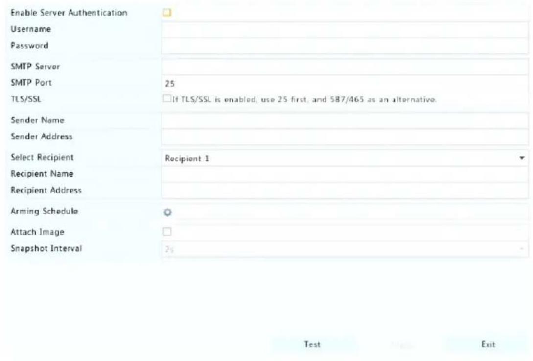

NOTE!
- Enter a valid SMTP server address and port number, and then select Enable TLS/SSL if required.
- Select Aach Image if you want snapshots to be sent via email. Make sure Email and snapshot have been enabled in the Trigger Acons window.
-
Only certain NVR models support image aachment. You may click Test to check whether the email can be sent successfully.
-
Click Apply to save the sengs.
FTP
Use this funcon to automacally upload images to a precongured FTP server. Only certain NVR models support this funcon.
- Click System > Network > FTP.
- Select the check box to enable FTP.
- Enter the IP address of the FTP server, username and password, remote directory, and upload interval.

NOTE!
- Click Test to verify whether an FTP conncon can be established.
-
If the remote directory is not specified, the system will create different folders directly by IP, me and camera. You may also specify a remote directly, for example, FTPtest/xxx/xxx, then the system will create the directory rst and then create folders by IP, me and camera.
-
Select the desired camera and then click right to Upload Schedule. In the Upload Schedule window, select the desired image type and set me periods.


NOTE!
- If you select Event, Moon, Alarm or Video Loss, you also need to congregate the corresponding alarm-triggered snapshot. For example, if you select Moon, you need to congregate alarm-triggered snapshot (select Moon in the Edit Schedule window).
-
To apply the same sengs to other days in a week, select the desired days right to Copy To.
-
(Oponal) Apply the same sengs to other cameras by clicking right to Copy and then selecng desired cameras.
- Click Apply to save the sengs.

SNMP
Use SNMP to connect to a plaorm and obtain system me.
1. Click System > Network. Select Enable SNMP.
| Enable SNMP | √ |
| SNMP Type | SNMPv2 |
| Read Community Name | public |
| Write Community Name | private |
| Trap Community Name | private |
| Trap Address | |
| Trap Port | 162 |
| SNMP Port | 161 |
Apply Exit
2. Select an SNMP type.
- Snmp V2
Set Read Community Name and Write Community Name, which are used by the plaorm to read data on NVR.
- Snmp V3
Set authencaon password (for the plaorm to access the NVR) and encrypon password (for encrypng data sent from the NVR to the plaorm).
3. Click Apply.
Mulcast
Mulcast can be used to realize live view when the number of connecng Web clients exceeds the limit the NVR can accommodate.
- Click System > Network > Mulcast.
- Select the check box to enable mulcast, and then enter the mulcast IP and port number.
| Enable Multicast | ✓ | ||
| Multicast IP | 206 . 7 . 102 . 232 | ||
| Port | 880 | ||
| Apply | Exit |
-
Click Apply to save the sengs.
-
Log in to the Web client and set Live View Protocol to Mulcast under Setup > Client.
12 Disk Conguraon
Disk Management
View disk informaon, including total and free disk space, disk status, disk type, disk usage, and disk property. Admin users can format disks and edit disk property.
- Click Storage > Hard Disk.
| No. | Total(GB) | Free(GB) | Status | Type | Usage | Prope... Edit | Delete |
| 1 | 0.00 | 0.00 | Abnormal | Local | Recording/Snaps... | Read/...✓ | |
| 2 | 2794.52 | 2300.75 | Normal | Local | Recording/Snaps... | Read/...✓ | |
| 3 | 2794.52 | 2281.25 | Normal | Local | Recording/Snaps... | Read/...✓ | |
| 4 | 2794.52 | 2288.75 | Normal | Local | Recording/Snaps... | Read/...✓ | |
| 5 | 2794.52 | 2319.75 | Normal | Local | Recording/Snaps... | Read/...✓ | |
| 6 | 2794.52 | 2331.75 | Normal | Local | Recording/Snaps... | Read/...✓ | |
| 7 | 2794.52 | 2278.00 | Normal | Local | Recording/Snaps... | Read/...✓ | |
| 8 | 2794.52 | 2281.25 | Normal | Local | Recording/Snaps... | Read/...✓ | |
| Refresh | Add | Format | Exit |
- To add a disk, click Add. In the dialog box displayed, select disk usage (recording/snapshot or backup) and disk type (currently NAS only), enter the server address and directory, and then click Add. Up to eight NAS disks are allowed.

- To edit disk property, click 🔒, and then modify disk usage (recording/snapshot or backup) and disk property (Read/Write, Read Only or Redundant) as needed.

NOTE!
- Disk property can be edited if the disk is used for recording/snapshot.
• The Redundant property is available to certain NVR models. -
You may use external eSATA disks for recording/snapshot or backup purpose and unmount them if necessary. eSATA disks and NAS disks cannot be used to create arrays.
-
To format a disk, select the disk and then click Format. A conrmaon message appears. Click Yes.

NOTE!
- Local disks will be formed automatically when installed. Extended disks will not.
- Format a disk with cauon. All data will be removed.
Array Conguraon
Only certain NVR models support RAID. The table below lists the supported RAID types and hard disks required.
| RAID | HDD Qty |
| RAID 0 | 2-8 |
| RAID 1 | 2 |
| RAID 5 | 3-8 |
| RAID 6 | 4-8 |
| RAID 10 | 4-16 (Must be an integral mulple of 2, e.g., 4, 8, 10, etc). |
| RAID 50 | 6-16 |
| RAID 60 | 8-16 |
Enabling RAID
You need to enable RAID rst.
- Click Storage > Array.
- Select the check box to enable RAID. A confirmaon message appears. Click Yes.
Creang an Array
It is recommended to congregate a hot spare disk to ensure reliable system operation and successful rebuilding in case an array fails.
- Click Storage > Array.
- To create an array automacally, click One-click Create.

NOTE!
- There is no need to select disks when creang an array with One-click Create. The system idenes all usable disks. RAID 1 is created when two disks are available. When three or more disks are available, RAID 5 is created. If more than four disks are available, a global hot spare disk will be created.
-
Arrays created in this way are named ARRAYX, for example, ARRAY1, ARRAY2.
-
To create an array manually, select the desired disks and then click Create. In the window displayed, enter the array name, select the array type, and select local disks. Click OK to complete the setup. Note that no hot spare disk will be created automacally. Make sure all disks are selected to create array(s); otherwise, disk space will be wasted (because disks that are not selected will not be used for storage).
Rebuilding an Array
By checking array status you can determine whether maintenance is necessary.

NOTE!
To be alerted when an array is degraded or damaged, you can congregate alarm-triggered acon at Alarm > Alert.
An array is in one of four statuses: normal, degraded, damaged, rebuild. The status is normal if no physical disk is lost. When the number of physical disks lost reaches the specied value, the array is considered damaged. The status between normal and damaged is degraded. A degraded array can be recovered to normal status through rebuilding.

NOTE!
Take RAID 5 that consists of 4 disks as an example. The array is degraded when one disk is lost. When two disks are lost, the array is damaged.
A degraded array can be automacally rebuilt in ten minutes if these conditions are met: a hot spare disk is available; the capacity of the hot spare disk is not less than that of any disk in the array. A degraded array without a hot spare disk can only be rebuilt manually under Storage > Array > Array. By default the rst local disk that sases requirements is selected.
Deleng an Array

CAUTION!
Deleng an array will erase all data on it.
- Click Storage > Array > Array.
- Click 📄 for the array to delete. A conrmaon message appears. Click Yes.
Disk Group
Assign hard disks to a disk group and use the disk group to store recordings and snapshots of specied cameras. Dierent arrays can be assigned to dierent disk groups.
Redundant disks cannot be assigned to any disk group. Disk group informaon will be initialized if any disk in the group is formaed.
1. Click Storage > Disk Group.
| Enable Disk Group | ||||||
| Disk List | ||||||
| No. | Total(GB) | Free(GB) | Status | Type | Property | Disk Group |
| 1 | 0.00 | 0.00 | No Disk | Local | - | - |
| 2 | 1863.02 | 0.00 | Normal | Local | Read/Write | Disk Group 1 |
- Select Enable Disk Group. By default all disks belong to Disk Group 1. Click for the disk to edit, and then select a group to which the disk will be assigned.

- Click Apply to save the sengs.
Space Allocaon
Allocate space to store videos and snapshots of a specied camera.
1. Click Storage > Allocate Space.
| Camera | D1 |
| Used Recording Space(GB) | 1 |
| Used Image Space(GB) | 0 |
| Select Group | Disk Group 1 |
| Disk Capacity | 1863 GB free of 1863 GB |
| Group Capacity | 1863 GB free of 1863 GB |
| Max Recording Space(GB) | 0 |
| Max Image Space(GB) | 0 |
- Select the desired camera and then set the maximum recording space and maximum image space. You can select a disk group only
when disk group is enabled under Storage > Disk Group. For more informaon, see Advanced Conguraon.
- Click Apply to save the sengs.
- (Oponal) Click Copy to apply the same sengs to other camera(s).
Advanced Conguraon
Set whether to overwrite recordings or snapshots when storage is full.
- Click Storage > Advanced.

- Choose an opon.
| Opon | Allocated Space | Descripon |
| Overwrite | 0 | The camera shares unallocated space, and its oldest recordings/snapshots will be overwrien when the space is used up. |
| Other values | The camera's oldest recordings/snapshots will be overwrien when its allocated space is used up. | |
| Stop | 0 | The camera shares unallocated space, and its oldest recordings/snapshots will sll be overwrien when the space is used up. |
| Other values | The camera's new recordings/snapshots will not be saved when its allocated space is used up. |
- Click Apply to save the sengs.
Hard Disk Detecon
S.M.A.R.T. Test
Click Maintain > HDD > S.M.A.R.T. Test to do S.M.A.R.T. test.
S.M.A.R.T. (enabled by default) checks the head, plaer, motor, and circuit of hard disks to evaluate their health status. The overall evaluaon results include Healthy, Failure, and Bad Sectors. It is recommended to replace the disk immediately if the status is Failure.
| Select Disk | Slot2 | ||||||
| Test Type | Short | ||||||
| Test Status | Not tested | ||||||
| Vendor | SEAGATE | ||||||
| Model | ST2000VX000-9YW1CV12 | ||||||
| Disk Temperature(°C) | 39 | ||||||
| Operation Time(day) | 804 | ||||||
| Self-Evaluation | Pass | ||||||
| Overall Evaluation | Healthy | ||||||
| ID | Attribute Name | Status | Flag | Threshold | Value | Worst | Raw Value |
| 1 | Raw_Read_Error_Rate | Healthy | 0x000f | 6 | 115 | 99 | 85936664 |
| 3 | Spin_Up_Time | Healthy | 0x0003 | 0 | 96 | 94 | 0 |
| 4 | Start_Stop_Count | Healthy | 0x0032 | 20 | 100 | 100 | 354 |
| 5 | Reallocated_Sector_Count | Healthy | 0x0033 | 36 | 100 | 100 | 0 |
| 7 | Seek_Error_Rate | Healthy | 0x000f | 30 | 85 | 60 | 36859343. |
| 9 | Power_On_Hours | Healthy | 0x0032 | 0 | 78 | 78 | 19310 |
| 10 | Spin_Retry_Count | Healthy | 0x0013 | 97 | 100 | 100 | 0 |
| 12 | Power_Cycle_Count | Healthy | 0x0032 | 20 | 100 | 100 | 343 |

NOTE!
- Some hard disks only support some of the test items.
- The system provides three test types: Short, Extended, and Conveyance. Extended tests detect more thoroughly and thus take longer me than Short tests. Conveyance tests mainly detect data transmission problems.

CAUTION!
Using a faulty disk is risky. Faulty disks should be replaced immediately. Contact your local dealer for informaon about hard disks.
Bad Sector Detecon
Bad sector detecon checks for bad sectors in hard disks.
- Click Maintain > HDD > Bad Sector Detect.

- Select the desired disk and detecon type, and then click Detect to start detecon. Click Stop if you want to stop.
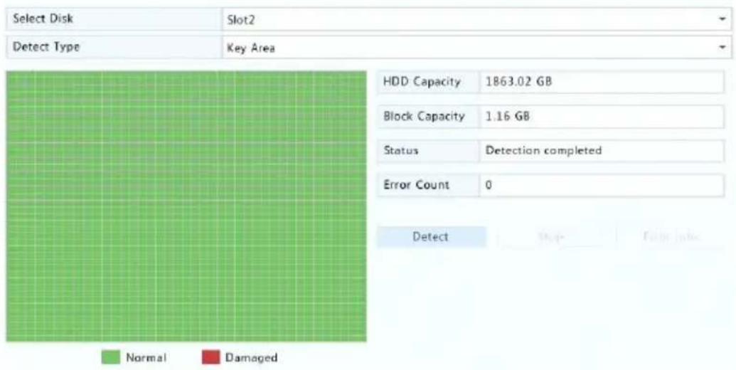

CAUTION!
The detecon stops automacally when the error count reaches 100.
Basic Conguraon
- Click System > Basic.
- Congure the parameters.

NOTE!
- Only admin can set Enable Password.
- If Enable Password is not selected, no password is required for local login at system startup. However, a username and password are sll required when you log in aer a logout.
- Some NVR models support Intelligent Mark. When the NVR and IP camera are both enabled, the latest areas/lines or VCA data congured for face detecon, intrusion detecon, and cross line detecon will be displayed on the Preview, Behavior and Alarm windows in real me.
- Intelligent mark is displayed on the screen as areas/lines in dierent colors. Yellow means areas/lines congured for face detecon, intrusion detecon, and cross line detecon; green means VCA data has changed but not triggered rules; red means rules are triggered in the congured area (rules are congured for VCA alarms), and VCA alarm has occurred.
• You may also set startup Wizard here by clicking Wizard.
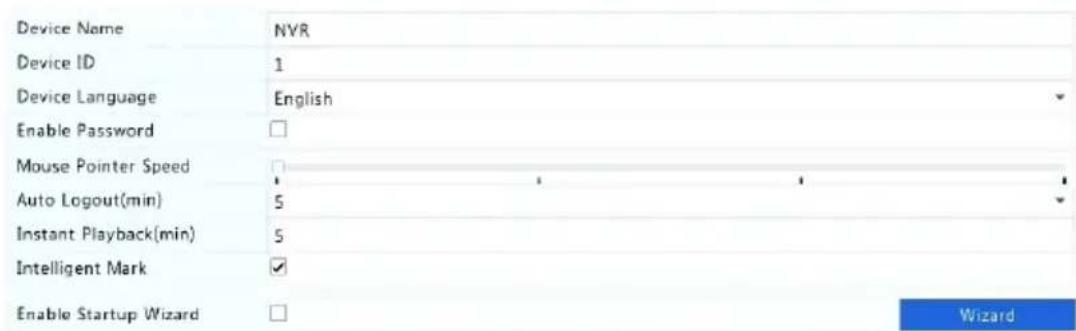
- Click Apply to save the sengs.
Time Conguraon
Time
- Click System > Time > Time.
- Select the correct me zone, and then set date and me formats and the system me. The following shows an example.
| Time Zone | (GMT+08:00) Beijing, Hong Kong, Urumqi, Singapore, Taipei | |||||||||
| Date Format | YYYY-MM-DD | |||||||||
| Time Format | 24-hour | |||||||||
| System Time | 2017 | - | 06 | - | 20 | ← | 14 | ; | 27 | ; 35 |
| Enable Auto Update | ||||||||||
| NTP Server Address | 0.0.0.0 | |||||||||
| NTP Port | 123 | |||||||||
| Update Interval | 10m | |||||||||
- To use Network Time Protocol (NTP), enable auto update, set the address and port number of the NTP server, and the update interval.
- Click Apply to save the sengs.
DST
- Click System > Time > DST.
- Enable DST by selecng the check box, and then set the start me, end me, and DST bias correctly. The following shows an example.
| Enable DST | |||||
| From | Mar | 2nd | Sun | 2 | |
| To | Nov | 1st | Sun | 2 | |
| DST Bias | 60 Minutes | ||||
- Click Apply to save the sengs.
Time Synchronizaon
Use this funcon to synchronize camera me with the NVR. Time sync is enabled by default, and cameras will synchronize me with the NVR aer geng online, and then synchronize once every 30 minutes.
- Click System > Time > Time Sync.
2. Select Sync Camera Time and then click Apply.

CAUTION!
Use this funcon with cauon if you have more than one NVR on the network. An IP camera synchronizing me with mulple NVRs at the same me will cause chaotic recordings.
Transacon Conguraon
This funcon is intended for the scenario such as in a café or a supermarket where the NVR is connected to a POS machine. When congured properly, the NVR obtains data from the POS machine and displays informaon in form of text with video images on the monitor.
Only certain NVR models support this funcon.
- Click System > Transacon.
- Click Add and then complete sengs in the window displayed.

NOTE!
- The name entered should be unique.
- The start idener, end idener, and line delimiter should be hexadecimal characters. The ignore characters are character strings that cannot be displayed.
- The source address is the IP address of the POS machine, and the desnaon address is that of a selement center that receives POS data. An empty desnaon address means it is necessary for the NVR to forward POS data.

- Set POS OSD under System > Transacon, including the posion, font and color of POS informaon displayed on the screen.
Serial Port Conguraon
Only certain NVR models support this funcon.
Serial port sengs in the NVR should be consistent with those in the connected serial device. Serial port conguraon is required for PTZ control.
- Click System > Serial.
- Congure the parameters for the serial port.
3. Click Apply to save the sengs.
User Conguraon
Add, delete users or edit user permissions. Only admin can perform these operaons.
A user type is a set of permissions in the system. When a user type is assigned to a user, this user has all the permissions specified for the user type.
There are four user types in the system:
- Admin: Default super administrator in the system, has full system access. Its initial password is 123456.
- Default: Default user reserved in the system, cannot be created or deleted, and only has access to live view and two-way audio. If the default user is denied access, the corresponding channel is locked when no user is logged in, and appears in the window.
- Operator: Has basic permissions and access to cameras.
- Guest: Only has access to cameras by default.
1. Click System > User.
| Username | User Type | Edit | Delete |
| admin | Administrator | ||
| default | Reserved User | ||
| user1 | Operator | ||
| user2 | Operator |
-
To add a user, click Add, and then set the username, user type, password and permissions as needed. Click OK to save the sengs.
-
To edit or delete a user, click 📄 or 📋 as needed. If you change the password for a user, the new password takes eect at the user's next login.
Security Conguraon
IP Control
Use this funcon to enhance security by allowing or forbidding access to the NVR from specied IP addresses.
- Click System > Security > IP Control.
- Select Enable IP Control, select Blacklist or Whitelist from the drop-down list, set the start and end IP addresses, and then click Add.

NOTE!
- If Blacklist is selected, the NVR denies remote access from the IP address(es) on the list.
- If Whitelist is selected, the NVR only allows remote access from the IP address(es) on the list. However, if Whitelist is selected with no IP address specied, remote access to the NVR will be denied.
| Enable IP Control | ||||
| Control Type | Blacklist | |||
| Start IP | - | - | ||
| End IP | - | - | Add | |
| No. | Start IP | End IP | Edit | Delete |
| 1 | 204.4.1.15 | 204.4.1.15 | ||
- Click Apply to save the sengs.
ONVIF Authencaon
Enable ONVIF authencaon under System > Security > ONVIF Auth so a username and password will be required for ONVIF-based device access.
Select the check box and then click Apply.
| Enable Authentication | ✓ |
| Note: If enabled, a username and password will be required for access by ONVIF. | |
ARP Protecon
ARP protocol is used to associate an IP address to a hardware MAC address. ARP aacks mainly occur on LAN, in which aackers use forged IP and MAC addresses. APR protecon prevents this kind of aacks by verifying the gateway's MAC address in all access requests.
Note that changing the NIC working mode will disable ARP protecon automacally.
- Click System > Security > ARP Protecon.
| Select NIC | NIC1 |
| Enable ARP Protection | ✓ |
| Gateway | 204 - 4 - 1 - 1 |
| Gateway MAC Address | Auto |
- Select the desired NIC and then select Enable ARP Protecon.
- Obtain the gateway's MAC address automacally, or select Custom and input the MAC address.
- Click Apply to save the sengs.
802.1x
802.1x is a port-based network access control protocol mainly used to solve authencaon and security issues on LAN.
Only certain NVR models support this funcon. Note that changing the NIC working mode will disable 802.1x automacally.
- Click System > Security > 802.1x.
- Select the desired NIC and select the check box to enable 802.1x.
- Select the EAPOL version, and then enter the username and password of the authencaon server.
- Click Apply to save the sengs.
Video Watermark
Encrypt custom informaon in videos to prevent unauthorized alteraon.
- Click System > Security.
| Camera | D11(smart ipc) |
| Enable Watermark | √ |
| Watermark Content | 1212 |
- Select the desired camera and then select Enable Watermark.
- Enter watermark content.
- Click Apply to save the sengs.
Secure Password
Secure password species the permission of strong or weak password in dierent modes: friendly password and enhanced password.
- Click System > Security.
Password Mode
Friendly Password
Enhanced Password
Friendly Password: You must log in with a strong password except in the same network segment or three private network segments (10.0.0.0/8, 172.16.0.0/12, 192.168.0.0/24). Enhanced Password: You must log in with a strong password.
- Friendly password is enabled by default. You may enable Enhanced Password as needed.
- Friendly Password
If this opon is selected, a strong password must be used except when login from the same network segment or one of the three private network segments (10.0.0.0/8, 172.16.0.0/12, 192.168.0.0/24).
• Enhanced Password
If this opon is selected, a prompt for a strong password will appear when a weak password is detected. Also, only strong passwords are allowed for new users.

NOTE!
Only admin can congure secure password.
- Click Apply to save the sengs.
Hot Spare Conguraon
Only certain NVR models support this funcon.
With hot spare congured, when the working device fails, the hot spare takes over service of the working data. When the working device restores normal status, it takes over service from the hot spare, and data saved to the hot spare during the period of failure is transferred back to the working device to ensure reliable and consistent data storage.
- Click System > Hot Spare.
- Select a working mode, Normal (default mode) for working device, or Hot Spare for hot spare device.

Normal
You must add a hot spare device aer choosing this mode; otherwise, hot spare does not take eect. Click Custom Add and then enter device informaon, including IP address, port number and password. The username is xed to admin. Click Add.
Hot Spare
Select Hot Spare, and the current device will be a hot spare for other working devices. All the working devices that the current hot spare serves are listed.

NOTE!
- Aer the working mode is changed, the NVR will restart with some parameters and sengs changed.
- For a working device that switches to a hot spare, some of its funcons will be unavailable, and some sengs will be reset to defaults.
- If mulple working device fail at the same me with only one hot spare device available, one working device gets backup at a me.
14 System Maintenance
System Informaon
Click Maintain > System Info to view the basic NVR informaon for maintenance purpose.
System Info
View the basic informaon such as the device model, serial number, rmware version, build date and operaon me.
| Basic Info | |
| Product Model | NVR |
| Serial Number | 210235T0E51234567890 |
| Firmware Version | B3119P15 |
| Build Date | 2016-11-09 |
| Operation Time | 0 Day(s) 0 Hour(s) 48 Minute(s) |
Camera status
Click the Camera tab to view camera status (online or oine with possible oine cause) and status of alarm funcons such as moon detection, tampering, video loss and audio detecon. O means disabled, and on means enabled.
| Camera | Name | Status | Motion | Tampering |
| D1 | IP Camera 01 | Offline(Network Disconnected) | Off | Off |
| D2 | IP Camera 02 | Offline(Network Disconnected) | Off | Off |
| D3 | IP Camera 03 | Offline(Network Disconnected) | Off | Off |
| D4 | IP Camera 04 | Offline(Network Disconnected) | Off | Off |
| D5 | IP Camera 05 | Offline(Network Disconnected) | Off | Off |
| D6 | IP Camera 06 | Offline(Network Disconnected) | Off | Off |
Recording status
Click the Recording tab to view recording status and stream sengs.
| Camera | Name | Type | Status | Diagnosis | Stream Type | fps |
| D1 | IP Camera 01 | None | No Recording | Camera Offline | None | 0 |
| D2 | IP Camera 02 | None | No Recording | Camera Offline | None | 0 |
| D3 | IP Camera 03 | None | No Recording | Camera Offline | None | 0 |
| D4 | IP Camera 04 | None | No Recording | Camera Offline | None | 0 |
| D5 | IP Camera 05 | None | No Recording | Camera Offline | None | 0 |
| D6 | IP Camera 06 | None | No Recording | Camera Offline | None | 0 |
| D7 | IP Camera 07 | None | No Recording | Camera Offline | None | 0 |
| D8 | IP Camera 08 | None | No Recording | Camera Offline | None | 0 |
| D9 | IP Camera 09 | None | No Recording | Camera Offline | None | 0 |
| D10 | IP Camera 10 | Normal | Ongoing | Normal | Main Stream | 25 |
Online user
Click the Online User tab for informaon about users who are currently logged in.
| No. | Username | IP Address | Login Time |
| 1 | admin | 127.0.0.1 | 2016-04-13 23:03:55 |
Disk status
Click the Disk tab to view the hard disk status and disk properes.
| Disk No. | Total(GB) | Free(GB) | Status | Vendor | Property |
| 1 | 0.00 | 0.00 | No Disk | ||
| 2 | 1863.02 | 0.00 | Normal | SEAGATE | Read/Write |
| Total Capacity(GB) | 1863.02 | ||||
| Free Space(GB) | 0.00 | ||||
Decoding card status
Click the Slot Status tab to view the decoding card status. This funcon is available to certain NVR models only.
Network Informaon
Trac
Click Maintain > Network Info > Trac to view network trac informaon.

line
| NIC1 | Status | MAC Address | MTU | NIC Type | |------|--------|-------------|-----|----------| | NIC1 | Connected | 48.0e-63.0e-14.06 | 1500 | Self-Adaptive |Network Detecon
Click Maintain > Network Info > Net Detect.
To test network delay and packet loss rate, enter the test address and then click Test.

NOTE!
The test packet size is 3000 bytes by default and can be changed as needed.
Network Delay and Packet Loss Test
| Test Address | 204.4.1.17 | Test |
| Test Result | Delay: 1.137ms, Packet Loss: 0.000% |
To capture and save packets, select the USB storage device, specify the port number and IP address, and then click right to the desired NIC.
The captured packets are saved as a backup le in the root directory of the USB storage device. You may click Open to view the le.

NOTE!
- The packet size is 1520 bytes by default and can be changed as needed.
- The backup le of the captured packets is named in NIC name_me.pcap format.
- Packets cannot be captured if it is already started on the Web interface.
- If you use PPPoE or 3G/4G, a virtual NIC will appear in the list aer the dial-up succeeds, and you may capture packets sent to and from this NIC.
Network Sengs
Click Maintain > Network Info > Network to view network sengs.
3G/4G Connecvity
Click Maintain > Network Info > 3G/4G Connecvity to view 3G/4G parameters.
| 3G/4G | Off |
| IPv4 Address | 0.0.0.0 |
| IPv4 Subnet Mask | 0.0.0.0 |
| IPv4 Default Gateway | 0.0.0.0 |
| Preferred DNS Server | 0.0.0.0 |
| Alternate DNS Server | 0.0.0.0 |
PoE/Network Port Status
Only certain NVR models support this funcon.
Click System > Network Info to view port status. In the gure below, the blue port is in use. For PoE models, power informaon will be displayed.
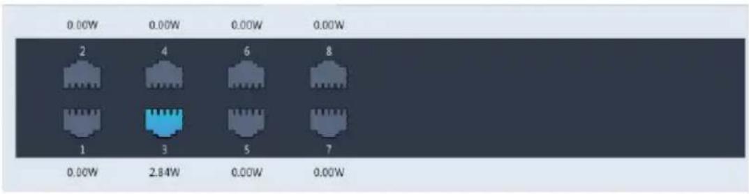
Network Stascs
Click Maintain > Network Info > Network Stascs. Bandwidth usage stascs are displayed.
| Type | Bandwidth |
| IP Camera | 15Mbps |
| Remote Live View | 0bps |
| Remote Playback | 0bps |
| Idle Receive Bandwidth | 145Mbps |
| Idle Send Bandwidth | 96Mbps |

NOTE!
- Insucient receiving bandwidth (Idle Receive Bandwidth) may cause the connected cameras to be oine.
- When the sending bandwidth (Idle Send Bandwidth) is insucient, remote live view, playback or download may fail on the NVR.
Log Query
Logs contain informaon about user-performed operaons and device status. By analyzing logs, you can keep track of device operaon status and view detailed alarm informaon.
- Click Maintain > Log.
- Set query conditions, including the start and end mes, main type and sub type.
- Click Query.
| Start Time | 2017 | - | 06 | - | 20 | 00 | : | 00 | : | 00 | |||
| End Time | 2017 | - | 06 | - | 20 | 23 | : | 59 | : | 59 | |||
| Main Type | All | ||||||||||||
| Sub Type | All Types | ||||||||||||
| Username | Operation Time | Camera | Play | Main Type | Sub Type | De | |||||||
| 2017-06-20 14:56:38 | D7 | Alarm | Motion Detection Ended | ||||||||||
| 2017-06-20 14:56:33 | D7 | Alarm | Motion Detection Started | ||||||||||
| admin | 2017-06-20 14:56:28 | Operation | Quick Search IP Camera | ||||||||||
| admin | 2017-06-20 14:56:23 | Operation | Login | ||||||||||
| 2017-06-20 14:55:57 | D13 | Alarm | Motion Detection Started | ||||||||||
| 2017-06-20 14:55:36 | D13 | Alarm | Motion Detection Ended | ||||||||||
| 2017-06-20 14:55:31 | D13 | Alarm | Motion Detection Started | ||||||||||
| 2017-06-20 14:55:15 | D13 | Alarm | Motion Detection Ended | ||||||||||
| 2017-06-20 14:54:55 | D13 | Alarm | Motion Detection Started | ||||||||||
| 2017-06-20 14:54:21 | D7 | Alarm | Motion Detection Ended | ||||||||||
-
If is displayed under Play, you may click to view the recording that started one minute before the alarm me and ended ten minutes aer the alarm me. means this funcons is not available.
-
To export logs to an external storage device, click Export, set the export desnaon and format, and then click Backup.
Import/Export
System Import/Export
Conguraons and diagnosis informaon can be exported to a storage device and saved as les for backup. A conguraon le can also be imported to the NVR to restore conguraons. The conguraon le of an NVR can be imported to mulple NVRs of the same model if you want them to have the same sengs. If the imported conguraon le contains camera informaon, the related camera will be added to all the NVRs.
Only admin can perform these operaons.
- Click Maintain > Import/Export.
- To export device conguraons, specify the desnaon directory and then click Export. A .xml le will be created in the specied directory when export is completed.
- To import device conguraons, double-click the target folder containing the .xml le, select the le, and then click Import.

CAUTION!
Delete les with cauon. Deleted les cannot be recovered.
Diagnosis Info
The device can save diagnosis info for 14 days and will overwrite the oldest when space is full.
- Click Maintain > History Diagnosis Info.
| Device Type NVR | ○IPC | ||
| Current Diagnosis Info Export | |||
| No. | History Diagnosis Info | File Size | Modify Time |
| 1 | NVR_Log_20180306000000.tgz | 115KB | 2018-03-06 00:00:00 |
| 2 | NVR_Log_20180305000000.tgz | 108KB | 2018-03-05 00:00:00 |
| 3 | NVR_Log_20180304000000.tgz | 108KB | 2018-03-04 00:00:00 |
| 4 | NVR_Log_20180303000000.tgz | 107KB | 2018-03-03 00:00:00 |
| 5 | NVR_Log_20180302000000.tgz | 179KB | 2018-03-02 00:00:00 |
| 6 | NVR_Log_20180301000000.tgz | 157KB | 2018-03-01 00:00:00 |
| 7 | NVR_Log_20180228000000.tgz | 156KB | 2018-02-28 00:00:00 |
| 8 | NVR_Log_20180227000000.tgz | 151KB | 2018-02-27 00:00:00 |
| 9 | NVR_Log_20180212000000.tgz | 167KB | 2018-02-12 00:00:00 |
| 10 | NVR_Log_2018O211OOOOO.Otgz | 166KB | 2018-02-11 0O:O:O:O |
| 11 | NVR_Log_2018O21OOOOOO.Otgz | 163KB | 2018-02-1O 0O:O:O:O |
| 12 | NVR_Log_2018O2O9OOOOO.Otgz | 168KB | 2018-02-09 0O:O:O:O |
| 13 | NVR_Log_2O8OOOOO.Otgz | 17OKB | 2018-02-OB 0O:O:O:O |
| 14 | NVR_Log_2O7OOOOO.Otgz | 169KB | 2018-02-OT OO:O:O:O |
-
Select a device type:
-
NVR: For NVR, history diagnosis info is generated at 00:00 every day. To export history diagnosis info, click Export at the boom. To export current diagnosis info, click Export right to Current Diagnosis Info.
- IPC: For IPC, history diagnosis info is generated at 00:05 every day. Select channels and then click Export at the boom. To export current diagnosis info, click Export right to Current Diagnosis Info.

NOTE!
For IPC, diagnosis info is recorded based on channel, which means, if an IPC is added to mulple channels, all the channels will record diagnosis info for the IPC.
System Restoraon
Use this funcon to restore some or all factory default sengs. The NVR will restart automacally to complete this operaon. Recordings and operaon logs will not be deleted.
-
Click Maintain >Restore.
-
Click Default to restore factory default sengs except network and user sengs, or click Factory Default to restore all factory default sengs.
Automac Maintenance
Set the NVR to restart as scheduled and delete les (including recordings and snapshots) as needed. Only admin can perform this operaon.
- Click Maintain > Auto-Funcon.
- Set an auto-restart me, and choose a way to delete les automacally.
| Auto-Restart | Tuesday | 02:00 | |
| Auto-Delete File | Never | day(s) ago |

CAUTION!
Files deleted automacally cannot be recovered.
System Upgrade
Upgrade the NVR under Maintain > Upgrade locally (using an upgrade le saved in a USB storage device) or by cloud (through a cloud server).
To upgrade by cloud, ensure that the NVR is connected to a fully functional DNS server (congured under System > Network > Basic), and click Check to see whether a newer version is available. The me that a cloud upgrade takes is acted by network conneccon status.

CAUTION!
- Make sure power is not interrupted during upgrade. A power failure during system upgrade may cause startup failure. Use an Uninterrupted Power Supply (UPS) if necessary.
- Ensure network connectivity for a cloud upgrade.
15 Shutdown
Click Shutdown to log out, restart or shut down as needed. To shut down the NVR, you may also long-press the power buon on the front panel (if available) for around three seconds ll an on-screen message appears, and then click Yes.

Logout

Restart

Shutdown

CAUTION!
Unsaved sengs will be lost if the NVR is shut down unexpectedly, for example, due to a power failure. An incorrect shutdown during a system upgrade may cause startup failures.
Part II Web-Based Operaons
1 Before You Begin
You may access and manage your NVR remotely using a web browser on a PC (through the Web interface). Check the following before you begin:
- Access will be authenticated during login, and operaon permissions will be required.
- The PC is operang properly and has a network conncon to the NVR.
- The PC uses the Windows XP, Windows 7 or Windows 8 operang system.
- A Web browser has been installed on the PC. Microso Internet Explorer 8.0 or higher is recommended. Firefox, Chrome and Opera browsers are also supported.
- A 32-bit Web browser is sll required even if you are using a 64-bit operang system.

NOTE!
- The parameters that are grayed out on the Web GUI cannot be modified. The parameters and values displayed may vary with NVR model.
- The gures are for illustraon purpose only and may vary with NVR model.
2 Login
- Open a Web browser on your PC and browse to the login page by entering the IP address (192.168.1.30 by default) of your NVR.
You may need to install a plug-in as prompted at your rst login. Close the Web browser when the installaon starts. - In the login dialog box, enter the correct username and password (123456 for admin) and then click Login.

CAUTION!
The default password is intended only for your rst login. We strongly recommend you set a strong password to ensure account security.
- Strong: contains at least 8 characters from at least three of the four types: upper-case leer, lower-case leer, special character, digit.
- Medium: contains at least 8 characters from two of the four types: upper-case leer, lower-case leer, special character, digit.
- Weak: contains less than 8 characters from only one of the four types: upper-case leer, lower-case leer, special character, digit.
3 Live View
The Live View page is displayed when you are logged in. The following gure shows an example.

Table 3-1 Live View Window Control Buons
| Buon | Descripon | Buon | Descripon |
 | Two-way audio |  / / | Main/Sub stream |
 | Start or stop live view in all windows |  | Previous and next screen |
 | Switch screen layout |  | Full screen |
 | Select stream type |  | Shows the current frame rate, bit rate, resoluon, and packet loss rate |
 | Take a snapshot |  | Start zoom |
 | Local recording |  | Turn on or o audio; adjust sound volume. |
| [738S] | Adjust MIC volume |  | 3D posioning |
 | Open or close the control panel | ### | - |
 |

NOTE!
- The 📄 icon means two-way audio is available. Click to start two-way audio with the NVR or a camera (depending on where the icon is displayed).
- Only the main stream 📄 is displayed when the camera is oine or it supports only one stream.
- A snapshot le is named in this format: IP_camera ID_snapshot me. The snapshot me is in YYYYMMDDHHMMSSMS format.
- By default, snapshots are saved in this directory: C:\Users\username\Surveillance\Snap\system date. The system date is in yvyy-mm-dd format.
- A local recording is named in this format: IP_camera ID_S recording start me E recording end me. The recording start and end mes are in hh-mm-ss format.
- By default, local recordings are saved in this directory: C:\Users\username\Surveillance\Record\system date. The system date is in yyyy-mm-dd format.
4 Playback
Click Playback on the top to show the Playback page. The following gure shows an example.

Table 4-1 Playback Control Buons
| Buon | Descripon | Buon | Descripon |
 | Play/Pause |  | Stop |
 | Reverse |  | Slow down or speed up |
 | Rewind or forward 30 seconds |  | Rewind or forward by frame |
 | Previous or next period |  | Clip video/pause |
 | Save video clip |  | Take a snapshot |
 | Zoom |  | Adjust sound volume; turn on or o sound |
5 Conguraon
Click Setup on the top, and then click the menus on the le to congure parameters.
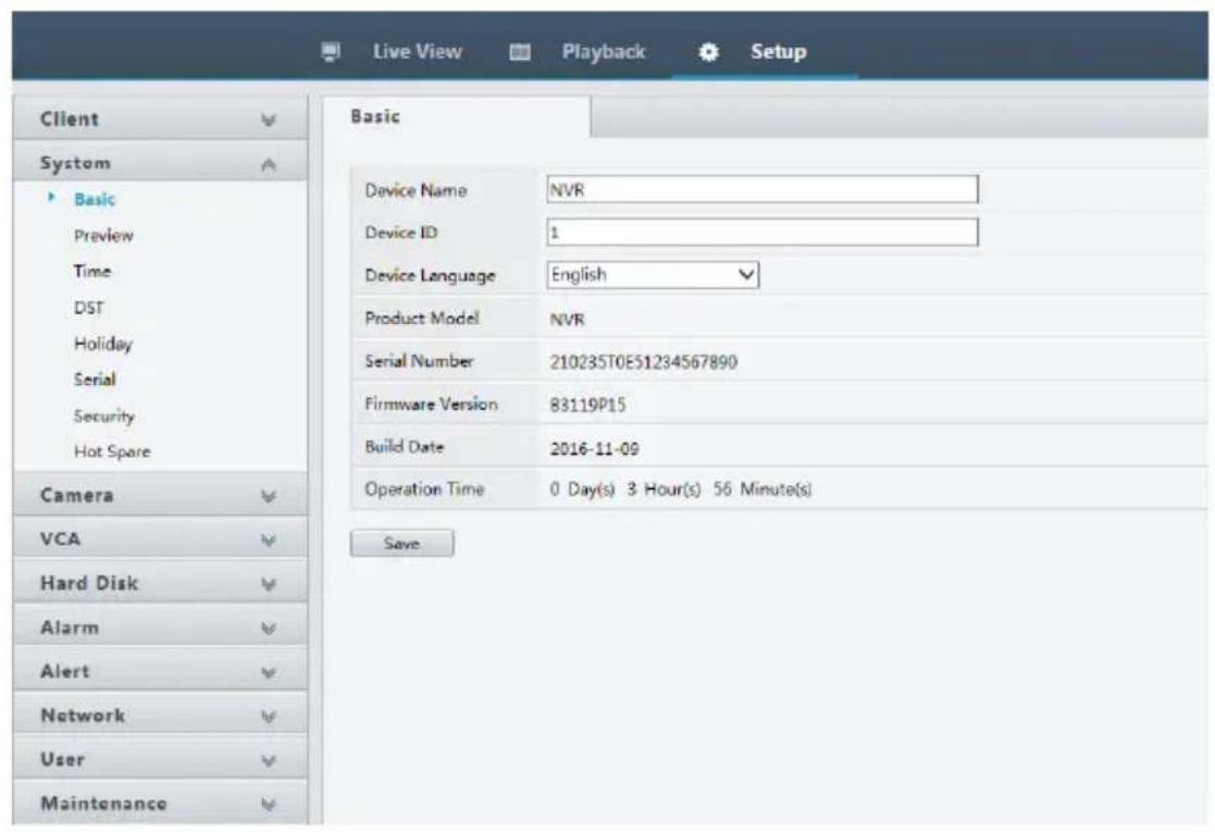
Typical Applicaon 1

flowchart
graph TD
    A["IPC1"] --> B["Switch"]
    C["IPCn"] --> B
    B --> D["NVR"]
    E["PC"] --> F["Monitor"]
    G["IPC1"] --> H["Switch"]
    I["IPCn"] --> H
    H --> D
    H --> E
The NVR, IP cameras, and PC are connected on a private network (or LAN). The IP cameras can be connected to the NVR directly or via a switch. And you manage the NVR and the connected IP cameras through the monitor or using a web browser on the PC.
Typical Applicaon 2

flowchart
graph TD
    IPC --> Switch
    Switch --> NVR
    NVR --> Monitor
    Monitor --> IPC1
    NVR --> IPCn
    Switch --> SurveillanceManagementSoftware
    style Switch fill:#99ccff,stroke:#333
    style NVR fill:#99ccff,stroke:#333
    style Monitor fill:#99ccff,stroke:#333
    style IPC1 fill:#99ccff,stroke:#333
    style IPCn fill:#99ccff,stroke:#333
    note right of Switch: Surveillance management software
The NVR, IP cameras, and PC are connected on a private network (or LAN). The IP cameras can be connected to the NVR directly or via a switch. The PC is installed with surveillance management soware. You can manage the NVR and the connected IP cameras using the surveillance soware or through the monitor.
Typical Applicaon 3

flowchart
graph LR
    A["NVR"] --> B["Router"]
    C["Cloud server"] --> D["Internet"]
    E["IPC"] --> A
    F["IPC"] --> A
    G["Mobile phone"] --> D
    H["Mobile phone"] --> D
    I["Web"] --> J["Mobile phone"]
The NVR and the connected IP cameras are located on a private network (or LAN), and you manage these devices through the cloud server, a cloud soluon for device management over Internet. Aer registering a cloud account and properly conguring your network devices (including router), you can manage your NVR and the connected IP cameras from a PC or a mobile phone.
Appendix B Acronyms
| Acronym | Descripon |
| CBR | Constant Bit Rate |
| DDNS | Dynamic Domain Name Service |
| DHCP | Dynamic Host Conguraon Protocol |
| DST | Daylight Saving Time |
| DVS | Digital Video Server |
| FTP | File Transfer Protocol |
| HDMI | High Denion Mulmedia Interface |
| HTTPS | Hypertext Transfer Protocol Over Secure Sockets Layer |
| IPC | IP Camera |
| JPEG | Joint Photographic Experts Group |
| MTU | Maximum Transfer Unit |
| NAT | Network Address Translaon |
| NIC | Network Interface Card |
| NTP | Network Time Protocol |
| NVR | Network Video Recorder |
| ONVIF | Open Network Video Interface Forum |
| PoE | Power over Ethernet |
| PPPoE | Point-to-Point Protocol over Ethernet |
| PTZ | Pan, Tilt, Zoom |
| P2P | Peer-to-Peer |
| RAID | Redundant Arrays of Independent Disks |
| RTSP | Real-Time Streaming Protocol |
| SDK | Soware Development Kit |
| S.M.A.R.T. | Self-Monitoring, Analysis and Reporng Technology |
| UPnP | Universal Plug-and-Play |
| USB | Universal Serial Bus |
| VGA | Video Graphics Array |
| VBR | Variable Bit Rate |
Appendix C FAQs
| Problem | Possible Cause and Soluon |
| Forgot the login password | Double-click the lower le corner of the login dialog box as admin. A dialog box appears.Note down the serial number and then contact your dealer for a temporary password. Log in with the temporarypassword and then reset your password.Use your mobile surveillance app to scan the QR code (Sengs > Forgot Device Password). |
| Cannot open the login page with the default IP address (192.168.1.30) | Please try 192.168.0.30. |
| The Web plugin (AcveX) cannot be loaded. | Close your web browser when the installaon starts.Disable the rewall and close the an-virus program on your computer.Enable your Internet Explorer(IE) to check for newer versions of the stored pages every me you visit the webpage (Tools > Internet Opons > General > Sengs).Add your NVR's IP address to the trusted sites in your IE (Tools > Internet Opons > Security).Add your NVR's IP address to the Compatibility View list in your IE (Tools > Compatibility View Sengs).Clear your IE's cache. |
| No images are displayed in live view on the Web interface. | Check if the bit rate is 0Mbps in the live view window.If yes, check if the rewall has been disabled, and the an-virus program has been stopped on your computer.If not, maybe it is because the graphics card driver on your computer is not working properly. Try installing the driver again. |
| A camera is oine, and No Link is displayed. | Click Maintain > System Info > Camera. The cause is displayed under Status. Common causes include disconnected network, incorrect username or password, weak password,insucient bandwidth.Check network conncon and network conguraons.If it indicates incorrect username or password, check that the camera password set in the NVR is the one used to access the camera's Web interface.If it indicates denied access for weak password, log in to the camera's Web interface and set a strong password.If it indicates insucient bandwidth, delete other online IP devices in the NVR. |
| The NVR displays live video for some cameras and No Resource for others. | Set the camera to encode the sub stream, and decrease its resoluon to D1.Set the NVR to use the sub stream rst for live view. |
| A camera goes online and oine repeatedly. | Check if network conncon is stable.Upgrade the rmware for the camera and the NVR. Contact your dealer for the latest versions. |
| Live view is normal, but the recording cannot be found. | Check that a recording schedule has been properly congured.Check if the me and me zone congured in the NVR are correct.Check if the hard disk storing the recording has been damaged.Check if the desired recording has been overwrien. |
| Moon detecon is not eecve. | Check that moon detecon is enabled, and the moon detecon area is properly congured.Check that detecon sensitivity is properly set.Check that the arming schedule is properly congured. |
| A hard disk cannot be idened by the NVR. | Use the power adapter delivered with your NVR.Power down the NVR and then mount the hard disk again.Try another disk slot.The disk is not compatible with your NVR.Contact your dealer for a list of compatible disk models. |
| The mouse does not work. | Use the mouse delivered with your NVR.Make sure no cable is extended. |


- Network Video Recorders
- User Manual
- Disclaimer
- CAUTION!
- Safety Symbols
- Contents
- Preface ....1
- Part I Local Operaons ....1
- Before You Begin....1
- Inial Conguration....7
- Live View....11
- Channel Configuraon 20
- PTZ Control....36
- Recording and Snapshot ....41
- Playback....53
- Backup....60
- Alarm....62
- VCA Search....77
- Network Conguraon ....80
- Disk Configuraon 92
- System Conguration.... 101
- System Maintenance .... 110
- Preface
- Part I Local Operaons
- Before You Begin
- Login
- Local Operaons
- NOTE!
- Mouse Operaons
- Front Panel Buons
- Remote Control
- Inial Conguraon
- Preparaon
- Wizard
- Enter the default admin password 123456 and then click Next.
- Complete me informaon and then click Next.
- Set a recording/snapshot schedule and then click OK.
- Live View
- Live View Status
- Shortcut Menu
- Sequence Operaon
- Zoom
- Image Conguraon
- Preview Conguraon
- Advanced Conguraon
- Channel Conguraon
- Channel Management
- Adding an IP Device
- Opon 1
- Opon 2
- Opon 3
- Opon 4
- Opon 5
- Managing an IP Device
- Sort Cameras
- Fisheye Conguraon
- Conguraon
- Dewarping
- Advanced Funcons
- OSD Conguraon
- Image enhancement
- Exposure
- Click the Exposure tab.
- Adjust the sengs as needed. Some important parameters are described in the table below.
- White balance
- Advanced sengs
- Privacy Mask Conguraon
- PTZ Control
- PTZ Control Window and PTZ Management Window
- Seng and Calling a Preset
- Seng a Preset Patrol
- Seng a Recorded Patrol
- Seng Auto Guard
- Recording and Snapshot
- Encoding Sengs
- Recording
- Click Camera > Encoding.
- Snapshot
- Draw or Edit a Schedule
- Scheduled Recording and Snapshot
- Scheduled Recording
- Scheduled Snapshot
- Moon Detecon Recording and Snapshot
- Moon Detecon Recording
- Moon Detecon Snapshot
- Alarm Triggered Recording and Snapshot
- Alarm Triggered Recording
- Alarm Triggered Snapshot
- Manual Recording and Snapshot
- Manual Recording
- Manual Snapshot
- Holiday Recording and Snapshot
- Holiday Recording
- Holiday Snapshot
- Other Recording and Snapshot Types
- Playback
- Instant Playback
- Playback Toolbar
- Playback by Camera and Date
- Playback in Corridor Mode
- Playback by Tag
- Adding a Tag
- Playback by Event
- Playback by Smart Search
- Playback by External File
- Playback by Image
- Playback by POS
- File Management
- Recording Backup
- Normal Backup
- Video Clip Backup
- Image Backup
- Alarm
- Alarm Input and Output
- Alarm Input
- Alarm Output
- Moon Detecon
- Tampering Detecon
- Video Loss
- VCA
- Basic Conguraon
- Face Detecon
- Intrusion Detecon
- Cross Line Detecon
- Audio Detecon
- People Counng
- Defocus Detecon
- Scene Change Detecon
- Auto Tracking
- Alert
- Buzzer
- Alarm-Triggered Acons
- Alarm-Triggered Buzzer
- Alarm-Triggered E-mail
- Alarm-Triggered Pop-up Window
- Alarm-Triggered Recording
- Alarm-Triggered Snapshot
- Alarm-Triggered Preset
- Alarm-Triggered Preview
- Alarm-Triggered Alarm Output
- Manual Alarm
- Manual Alarm Output
- Manual Buzzer
- VCA Search
- Behavior Search
- Face Search
- Network Conguraon
- TCP/IP
- Click Apply to save the sengs.
- PPPoE
- EZCloud
- Click Apply to save the sengs.
- DDNS
- Click System > Network > DDNS.
- 3G/4G
- Port
- Port Mapping
- UPnP
- Manual Port Mapping
- FTP
- SNMP
- Click System > Network. Select Enable SNMP.
- Select an SNMP type.
- - Snmp V2
- - Snmp V3
- Click Apply.
- Mulcast
- Disk Conguraon
- Disk Management
- Array Conguraon
- Enabling RAID
- Creang an Array
- Rebuilding an Array
- Deleng an Array
- Disk Group
- Click Storage > Disk Group.
- Space Allocaon
- Click Storage > Allocate Space.
- Hard Disk Detecon
- S.M.A.R.T. Test
- Bad Sector Detecon
- Time Conguraon
- Time
- DST
- Time Synchronizaon
- Select Sync Camera Time and then click Apply.
- Transacon Conguraon
- Serial Port Conguraon
- User Conguraon
- Click System > User.
- Security Conguraon
- IP Control
- ONVIF Authencaon
- ARP Protecon
- 802.1x
- Video Watermark
- Secure Password
- Hot Spare Conguraon
- Normal
- Hot Spare
- System Maintenance
- System Informaon
- System Info
- Camera status
- Recording status
- Online user
- Disk status
- Decoding card status
- Network Informaon
- Trac
- Network Detecon
- Network Sengs
- 3G/4G Connecvity
- PoE/Network Port Status
- Network Stascs
- Log Query
- Import/Export
- System Import/Export
- Diagnosis Info
- System Restoraon
- Automac Maintenance
- System Upgrade
- Shutdown
- Part II Web-Based Operaons
- Login
- Playback
- Conguraon
- Typical Applicaon 1
- Typical Applicaon 2
- Typical Applicaon 3
- Appendix B Acronyms
Brand : UniView
Model : NVR301-04S
Category : Video recorder