TC25 - Air conditioner ElectriQ - Free user manual and instructions
Find the device manual for free TC25 ElectriQ in PDF.


| Product Type | Portable Air Conditioner |
| Brand | ElectriQ |
| Model | TC25 |
| Cooling Capacity (BTU) | 9000 |
| Energy Efficiency Ratio (EER) | 2.6 |
| Refrigerant Type | R410A |
| Power Supply | 115V / 60Hz |
| Power Consumption (Cooling) | 1050W |
| Air Flow (CFM) | 180 |
| Noise Level (dB) | 52 |
| Dimensions (WxHxD) | 16.5" x 27.2" x 13.2" |
| Weight | 52 lbs |
| Coverage Area | Up to 250 sq ft |
| Control Type | Remote Control + Digital Display |
| Modes | Cool, Fan, Dehumidify |
| Fan Speeds | 3 (Low, Medium, High) |
| Timer | 24-hour programmable |
| Air Filter | Washable mesh filter |
| Maintenance | Clean filter every 2 weeks; drain condensate when full |
| Safety Features | Overheat protection, auto restart, child lock |
| Spare Parts / Repairability | Filter, remote, drain hose available; user-serviceable filter |
| Warranty | 1 year limited warranty |
Frequently Asked Questions - TC25 ElectriQ
User questions about TC25 ElectriQ
0 question about this device. Answer the ones you know or ask your own.
Ask a new question about this device
Download the instructions for your Air conditioner in PDF format for free! Find your manual TC25 - ElectriQ and take your electronic device back in hand. On this page are published all the documents necessary for the use of your device. TC25 by ElectriQ.
USER MANUAL TC25 ElectriQ
Commercial Air Conditioners
TC25 25,000 BTU
TC35 32,000 BTU
natural_image
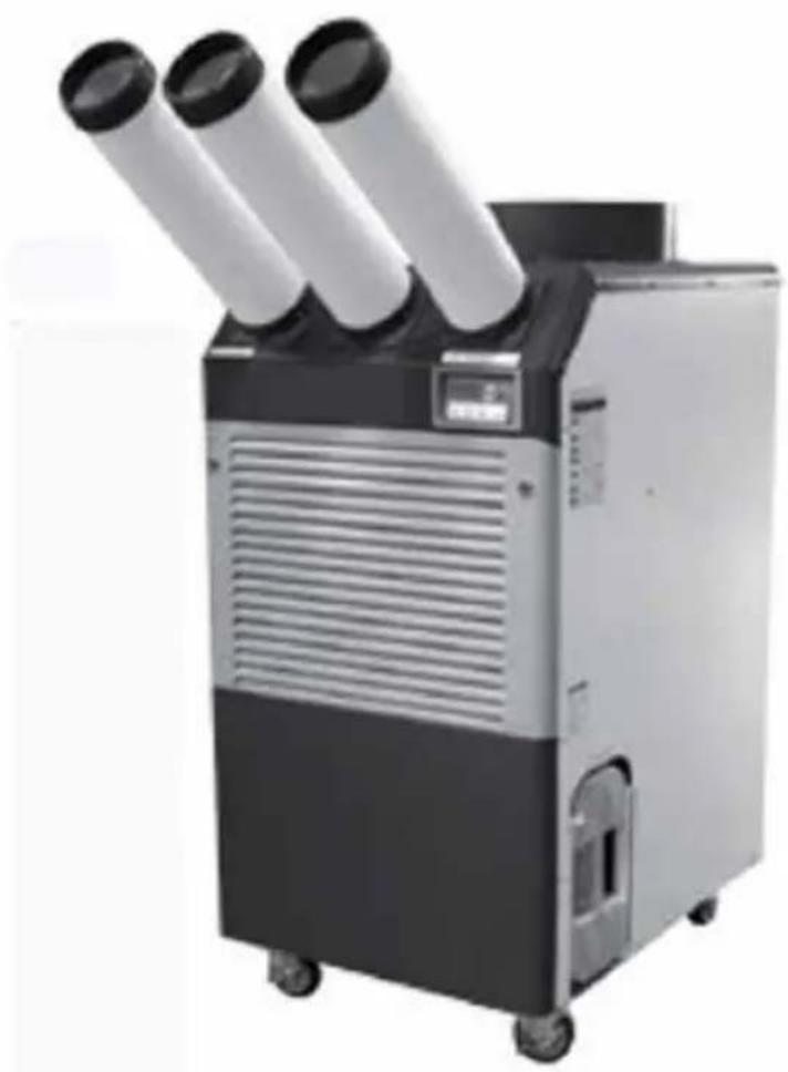
Exterior view of a three-wheeled air conditioning unit with three cylindrical pipes (no text or symbols visible)Thank you for choosing ElectrIQ
Please read this user manual before using this innovative
Commercial Air Conditioner
and keep it safe for future reference.
Visit our page www.electrlQ.co.uk for our entire range of Air Treatment products
Contents
Safety Instructions 2
Installation 5
Parts and Assembly 6
Control Panel&Operation 9
Care and Maintenance 10
Self Diagnostic Codes 13
Wiring Diagram 14
Troubleshooting 17
Technical Data 18
SAFETY INSTRUCTIONS
- Carefully read the instructions before operating the unit. If used on commercial premises the site manager should ensure that the operator has access to the user manual and understands the operation of the unit.
- This appliance is for indoor or dry environment applications and intended for use in a commercial or industrial environment. Any other use is not recommended by the manufacturer and may cause fire, electrical shocks or other injury to operator or property. While it can be used in domestic environment this air conditioner was not built with domestic safety standards.
- Rating: This unit must be only connected to a 220-240 V / 50 Hz earthed outlet or hardwiring. Always operate the unit with the grounding plug supplied. A grounding plug is a safety feature that helps reduce the risk of shock or fire. For TC35 please hardwire or use correct special 16 amp industrial wall socket and plug.
- If you are in any doubt about the suitability of your electrical supply have it checked and, if necessary, modified by a qualified electrician.
- This air conditioner has been tested and is safe to use. However, as with any electrical appliance - use it with care. This unit is a commercial / industrial unit and was not designed with children in mind. Do not allow children to play with or around this commercial unit, this could result in injury. Make sure the unit is not accessible to children either in use or not.
• Installation must be in accordance with regulations of the country where the unit is used.
- Disconnect the power plug from socket before dismantling, assembling or cleaning.
- Never connect the unit to an electrical outlet using an extension cord. If a power outlet is not available, one should be installed by a qualified electrician. Using extensions will lead to reduction of voltage supplied to the unit and overheating of the electrical cable at can only be done to customer risk
- Never operate this appliance if the cord, power adapter or plug is damaged. Ensure the power cord is not stretched or exposed to sharp object/edges.
- A damaged power supply cord should be replaced by the manufacturer or a qualified electrician in order to avoid a hazard.
- Avoid mishandling the air conditioner. Dropping, throwing the unit can cause damage to its internals and increases the risks of operating it.
- This air conditioner must not be used in spaces where there is a high concentration of gases, solvent or other volatile organic compounds; in very dusty environment; in any commercial or industrial environment where air composition is flammable.
- Avoid touching any moving parts of the appliance. Never insert fingers, pencils or any other objects though the guard
- This appliance is not intended for use by operators (including children) with reduced physical, sensory or mental capabilities. It is also not intended for use by those with a lack of experience and knowledge, unless they have been given supervision or instruction concerning the use of the appliance by a person responsible for their safety.
- Do not operate the air conditioner in pooled or standing water, as this may create a
risk of injury from electrical shock. If the case or the inside of the unit become wet dry the unit before restarting it. If fails to operate discontinue use and call the service centre.
- Do not clean the unit by spraying it or immersing it in water.
- Any service other than regular cleaning or filter replacement should be performed by an authorized service representative. Failure to comply could result in a voided warranty.
- Do not use the appliance for any other purposes than its intended use.
- Do not tilt the unit while in use. The unit is design to work only in vertical position. Always operate the unit on a stable, level surface e.g. solid floor, so that the unit cannot fall and cause accident.
- This air conditioner must always be stored upright, otherwise irreparable damage may be caused to its compressor.
- Rest for minimum 8 hours after been transported in horizontal position. Avoid restarting the air conditioner unit unless 5 minutes have passed since being turned off.
- Never use the mains plug as a switch to start and turn off the air conditioner. Use the provided ON/OFF switch located on the control panel.
• Always place the unit on a dry and stable surface.
- The unit should not be installed in laundry or wet rooms where the humidity is higher than 85% RH. Operate this unit in an ambient temperature between 5°C and 40°C.
- Avoid any water ingress into the air conditioner. Make sure no dust or wet building materials are entering the unit.
- Do not place the unit next to heat sources e.g. electric or gas fires, radiators, boilers etc.
Energy Saving and Unit Safety Protection Tips
- Do not cover or restrict the airflow from the outlet or inlet grills.
- For maximum performance the minimum distance from a wall or objects should be 60 cm in any directions
- Keep the filters or grills of the unit clean. Under normal conditions, filters or grills should only need cleaning once every two weeks (approximately). Do not use the unit without the air filter as this will allow dirt to gather inside the unit and could invalidate the warranty. A dirty filter will restrict the air flow into the machine which will increase the resistance on the fan and could result in damage and might invalidate the warranty.
Since the filters remove airborne particles, more frequent cleaning maybe necessary, depending on the air quality. Vacuum and wash the mesh filters with hot soapy water and dry them before placing them back in the unit. Do not allow grease, oil or any contaminants to be absorbed into the unit.
Features
Your ElectrlQ air conditioner is a top of the range commercial air conditioner
with features not found in other units
- Large 25,000 and respective 32,000 BTU ideal for commercial and industrial applications
- Metal body, ideal for hire or commercial operation
- Portable on large castors, efficient, easy to use
- LCD screen with Temperature display in Celsius or Fahrenheit
- Intelligent CPU controlled thermostat with exact settings and power saving logic
- Two speed fan for balance between better airflow and quieter operation
- Touch control panel with led indicator
- Timer off settings
- Self-diagnostic
- Optional permanent drainage with uplift pump
Electriq portable Air Conditioners also feature spot cooling for large areas where cooling of the entire area is not practical. A dedicated spot cooling thermostat controls the unit in this application.
These air conditioners can also be used in smaller areas for room cooling. A control panel provides ease of use and contains a self-diagnostic function and display, showing operating modes, room and set temperatures, and if the case faults. If an abnormal operation occurs, a visual display of the fault is shown.
Great for commercial and industrial applications including factories, open plan offices, commercial kitchens, computer rooms, boiler rooms, emergency cooling, outdoor event, etc.
Installation
Place the unit on a hard / flat surface. On first use run the unit continuously for 24 hrs. While used indoor, in order to save energy, do not open windows or doors while the unit is running.
To reduce noise levels:
Place a rubber mat under the entire unit to reduce any vibrations while the unit is running.
ElectrIQ commercial air conditioners use compressor technology to cool down and enclose space or act as spot coolers. The ElectrIQ range of commercial air conditioners are cooling on ambient temperatures ranging between 18°(64°F) - 45°C (113°F). We recommend not using the units if ambient temperature is out of prescribed range as this could damage the units.
ElectrIQ commercial air conditioners are easy to move around on large wheels. They are also intelligent air conditioners which will cool down to desired settings while saving money due to their thermostat and advanced power saving logic.
They also feature a spot cooling mode ideal for commercial or industrial applications.
Assembly and Parts TC25
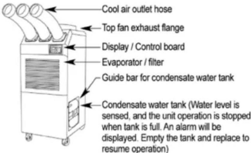
COMPONENT PARTS
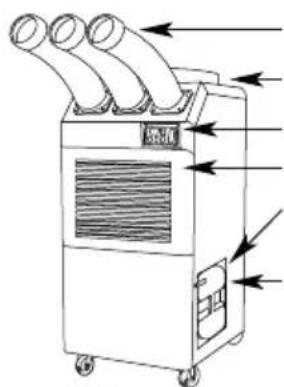
Figure 2 Front and Right Side View
Cool air outlet hose
Display / Control board
Evaporator / filter
Guide bar for condensate water tank
Condensate water tank (Water level is sensed, and the unit operation is stopped when tank is full. An alarm will be displayed. Empty the tank and replace to resume operation)
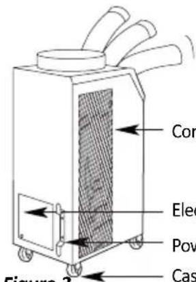
Figure 3 Back and Left Side View
Condenser / filter
Electrical access panel
Power cord holder
Caster
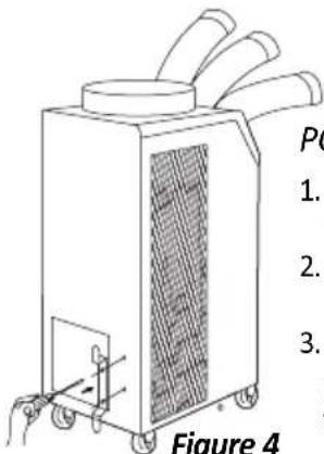
Figure 4
POWER CORD HOLDER
- Take out the cord holder from the accessory box.
- Place the cord holder on the back side of air conditioner.
- Use screws (enclosed inside of accessory box with cord holder) to install the cord holder on the air conditioner as shown in Figure 10.
natural_image
Line drawing of a three-wheeled air conditioner unit with cooling fan and control panel (no text or symbols)Figure 5
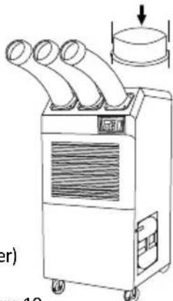
TOP FAN EXHAUST FLANGE
- Remove the top fan exhaust flange from carton.
- Place the top fan exhaust flange on the top of air conditioner.
- Use screws (enclosed inside of box with the top fan exhaust flange) to install the top fan exhaust flange on air condition as shown in Figure 5.
natural_image
Line drawing of a portable air conditioner unit with three tubes and a handle (no text or symbols)Figure 6
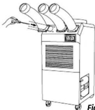
DISCHARGE DUCTS/SUPPLY AIR DUCT
- Remove cool air outlet hose(s) from carton.
- Place the cool air outlet hose(s) on the front top of air conditioner.
- Use screws (enclosed inside of box with cool air outlet hose(s) to install the cool air outlet hose(s) on the air conditioner as shown in Figure 6.
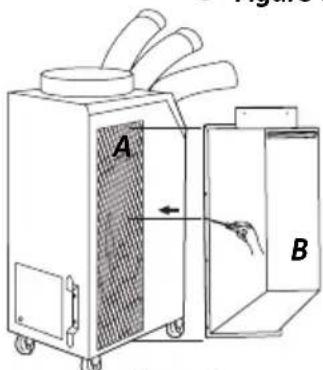
Figure 7
AMBIENT AIR ADAPTER (Optional)
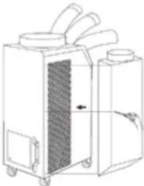
An ambient air adapter can be purchased separately. Air adapter fits over the condenser to duct condenser air to the unit to improve cooling efficiency.
- Remove the Filter("A")
- Check the Filter("C") is inserted properly in Intake Warm Air Duct("B")
- Install "B" which contains "C" by using driver with enclosed bolts(6EA) as Figure 7.
TC35
COMPONENT PARTS
Front and Right Side View
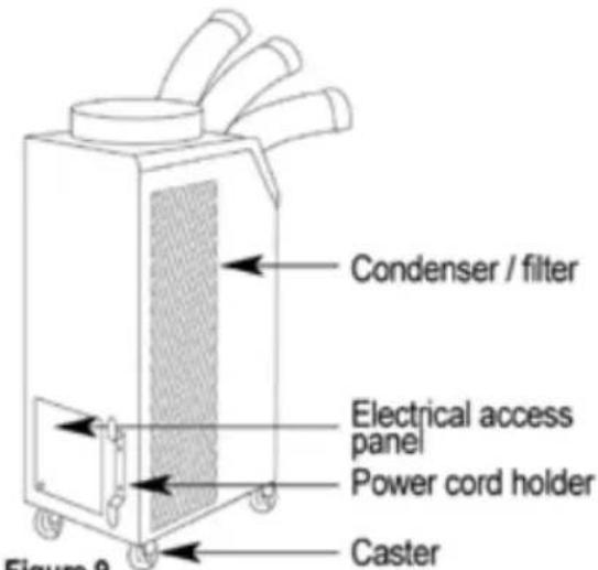
Back and Left Side View
POWER CORD HOLDER
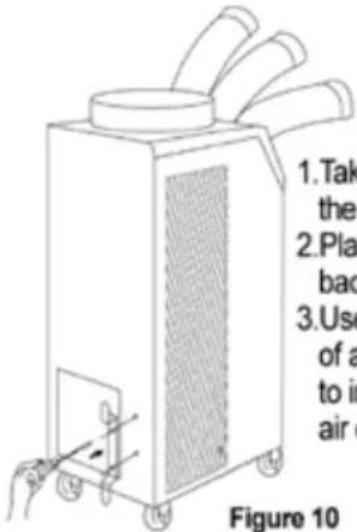
- Take out the cord holder from the accessory box.
- Place the cord holder on the back side of air conditioner.
- Use screws (enclosed inside of accessory box with cord holder) to install the cord holder on the air conditioner as shown in Figure 10.
TOP FAN EXHAUST FLANGE
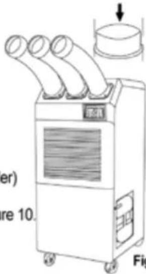
Figure 11
- Remove the top fan exhaust flange from carton.
- Place the top fan exhaust flange on the top of air conditioner.
- Use screws (enclosed inside of box with the top fan exhaust flange) to install the top fan exhaust flange on air conditioner as shown in Figure 11.
DISCHARGE DUCTS/SUPPLY AIR DUCT
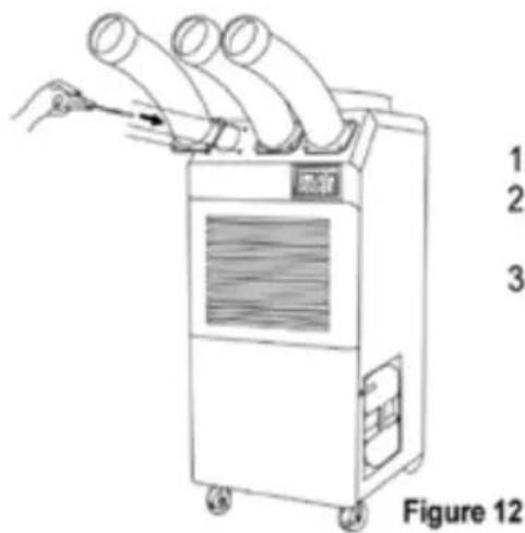
- Remove cool air outlet hose(s) from carton.
- Place the cool air outlet hose(s) on the front top of air conditioner.
- Use screws (enclosed inside of box with cool air outlet hose(s) to install the cool air outlet hose(s) on the air conditioner as shown in Figure 12.
natural_image
Line drawing of a portable industrial machine with wheels and a vent, showing internal structure and no text or symbols.Figure 13
An optional condenser plenum can be purchased. Condenser plenum fits over the condenser to duct condenser air to the unit to improve cooling efficiency.
- Remove condenser plenum from carton.
- Place condenser plenum on the rear of air conditioner.
- Use screws (enclosed inside of box with condenser plenum) to install the condenser plenum on the air conditioner as shown in
Figure 1
Unlock the casters and push the unit using the side handles to a flat, level surface. Once in position please secure the castors by engaging the lock position.
Do not install the unit on uneven surface. The unit may roll or topple over even if the castors are set to the locked position.
PLUGGING IN THE UNIT
Check the surface of the power cord and plug for dust/dirt. If dust and/or dirt are present, wipe off with a clean, dry cloth. Check the power cord for damage or excess use.
If any damage or excess use is found, contact a qualified repair technician or a qualified electrician to perform replacement or repair.
Ensure TC35 is hard wired or fitted with special industrial 16Amp plug and you
Operation CONTROL PANEL
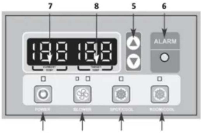
Figure 14 1 2 3 4
- POWER BUTTON (ON/OFF): Activates unit when POWER BUTTON is pressed. (Fan starts on low speed). If power button is pressed during operation, unit stops.
- BLOWER BUTTON: Changes fan speed from (Low) to (High) when pressed.
- SPOT/COOL BUTTON: Activates compressor and begins producing cool air 5 seconds after button is pressed. Regulates temperature based on outlet cool air temperature.
- ROOM/COOL BUTTON: Activates compressor and produces cool air 5 seconds after button is pressed. Regulates temperature based on inlet ambient air temperature.
- SET TEMP BUTTONS: Change target temperature/data value by +/- 1 increments. You can increase by +/- 10 by holding the button. Arrow up button is to increase temperature and arrow down button is to lower temperature.
- ALARM: Alarm indicator lights (blinks) and indicates abnormal system operation. If Alarm occurs, compressor stops. System operation stops when ALARM light is activated (blinks) for longer than 3 minutes.
- CURRENT TEMP: Displays current room temperature in display in Celsius. (In Room Cool Mode only). SPOT/COOL Mode – Displays outlet (cool air) temperature during normal operations. In order to change °C to °F, press SPOT/COOL and ROOM/COOL buttons together for 2 seconds. F will blink 2 times and Figure will change to °F. ALARM codes blink and are displayed when abnormal operation occurs.
- TARGET TEMP: displays the unit set temperature for ROOM/COOL mode only.
OFF-TIMER: Enter to Timer Setting Mode if you press BLOWER Button and SPOT/COOL Button together for 1 seconds. Press UP / DOWN Button to set the timer until it shows the figure you want to set. After 5 seconds, the figure will be memorized and the compressor will stop after the time set.
AUTO RESTART: If there is a power cut the unit will automatically restart when the power resumes.
Care and Maintenance
Always switch off the unit and unplug from the mains before cleaning or performing any maintenance. When it is not in use for long periods it is advisable to remove the plug from the plug socket. Do not use chemical solvents (such as benzene, alcohol or gasoline) as they may cause irreversible damage to the unit.
Air-inlet and air-outlet may gather dust easily, please clean it often with a soft, damp cloth. If the filters are covered by dust, the airflow and the performance of the unit will be affected, it may even cause machine damage. We recommend that you regularly clean the filter. Let the unit dry before reuse.
FILTER CLEANING
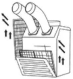
- To clean the evaporator filter, pull the front filter guard forward from the top until the guard is open (in an angled position) and resting on the supporting cables.
- Slide the filter up and use a vacuum cleaner to remove the dust from the filter.
- If the filter is heavily covered with dust and dirt, warm water and mild soap or neutral detergent may be used to wash the filter. Do not use any other chemicals to clean the filter, as they will likely damage the filter.
- Dry the filter in a shaded area before replacing it. Do not operate the unit without the filter installed and the filter guard in the closed position.
Replace the clean filter and close the filter guard. - To clean the condenser filter, lift up on the rear or side filter from the middle bar slightly and then angle the filter outwards from the bottom and remove.
- Use the same cleaning procedure as in steps 3-5 above.
- To replace the condenser filter, place the top of the filter in the guide and slide the filter up until the bottom of the filter clears the frame. Then push the bottom of the filter into the guide and let the filter gently fall inside the guide.
NOTE: For effective cooling, clean the filter at least every 2 weeks.
Grille and Case Cleaning
Use water and a mild detergent. Do not use bleach or abrasives. Do not splash water directly onto the main unit. Doing so may cause an electrical shock and can lead to the insulation to deteriorate, or cause the unit to rust. The air intake and outlet grilles get soiled easily, so use a vacuum attachment or soft brush to clean.
natural_image
Diagram of a heat exchanger or cooling unit with two pipes and airflow arrows indicating airflow direction (no text or labels)TC25
- Loosen up 2 bolts on the front filter guard.
- Slide filter up and use a vacuum cleaner to remove the dust from the filter.
- Lift up on the side filter from the middle bar slightly and then angle the filter outwards from the bottom and remove.
Figure 15 - Removing Filters
TC35
natural_image
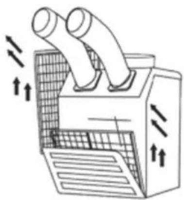
Diagram of a turbocharger with airflow arrows indicating heat transfer (no text or labels)- Loosen up 2 bolts on the front filter guard.
- Slide filter up and use a vacuum cleaner to remove the dust from the filter.
- Lift up on the side filter from the middle bar slightly and then angle the filter outwards from the bottom and remove.
natural_image
Illustration of a solar panel installation with sun and roof structure (no text or symbols)Figure 17 – Removal of Dust
Figure 16 - Removing Filters
Remove dust from the filter using a vacuum cleaner hose attachment.
if required wash the filter in lukewarm water with a mild detergent. Leave to dry in a shaded area before reinstalling.
Do not operate without the filter fitted.
Do not operate the unit with a damaged cord or plug, after the unit malfunctions, or if the unit has been dropped or damaged.
natural_image
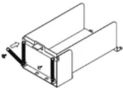
Technical line drawing of a mechanical housing or enclosure with mounting feet and internal components (no text or symbols)Figure 18 – The process of spring replacement
SPRING REPLACEMENT (See Figure 18)
There are two springs on the rear of condensate water tank guide.
- Release the screw on the spring hook.
- Take off the spring hook, and then pull out the opposite spring hook from hole in the condensate water tank guide.
- Replace with a new spring in reverse order.
- Repeat this cycle for the other spring.
Out of season storage
- Turn off the unit and wait for the drying cycle to finish before unplugging the power cord.
- Clean and dry the water-tank.
- Clean the filter, air-inlet, air-outlet and unit body.
- Coil the power cord in the holder
- Cover the unit to prevent it from gathering dust.
- Store the air conditioner in a cool and dry place in vertical position
Power Cord Maintenance and Replacement
If the power cord is damaged, it could cause a short circuit or become a fire risk. Please avoid pulling the cord, twisting or pressing it and keep it away from pets. If the power cord is damaged, power the unit off and unplug if immediately. Contact an electrician for repairs; do not attempt to repair the unit yourself.
SELF-DIAGNOSTIC CODES (See Table 1)
The alarm light is activated if abnormal operation occurs, and a code is displayed on the control panel. The compressor and condenser fan motor will stop operating. The evaporator fan will continue to run for 3 minutes. If the fault is rectified within 3 minutes, the unit will resume operation. If the fault persists for more than 3 minutes, the evaporator fan also stops. The fault must be rectified before the unit can resume normal operation.
| SELF-DIAGNOSTIC ALARM CODES | |||
| Alarm Display | Problem | Cause | Corrective Action |
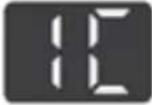 | Frost prevention sensor and abnormal temperature sensor value | · Indoor heat exchanger temperature too low· TH3 temperature sensor has a loose or broken connection | · Do not use the air conditioner if ambient temperature is lower than 18°C (64°F)· Contact a qualified service agent |
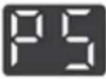 | Refrigerant high pressure switch | · Blocked air filter· Blocked / kinked exhaust duct· Ambient temperature is too high | · Clean air filter· Ensure exhaust duct is not blocked / kinked· Do not use the air conditioner if ambient temperature is higher than 45°C (113°F) |
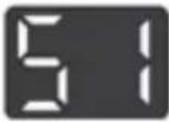 | Abnormal temperature sensor value | TH1 (Outlet) temperature sensor has a loose or broken connection | Contact a qualified service agent |
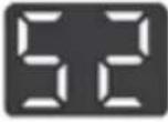 | Abnormal temperature sensor value | TH2 (Inlet) temperature sensor has a loose or broken connection | Contact a qualified service agent |
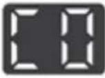 | Compressor overloaded | · Ambient temperature is too high· Unstable voltage supply· Defective compressor | · Do not use the air conditioner if ambient temperature is higher than 45°C (113°F)· Contact a qualified service agent· Replace compressor |
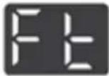 | Condensate water level alarm | Condensate tank is full | Empty the water tankAfter installation of the water tank, press the SPOT/COOL or ROOM/ COOL button to resume operation |
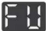 | Drain pump alarm | Drain pump defective or improper hose connection (including kink or blockage) | Check the connection and hoseReplace drain pump |
Table 1- Alarm Codes
Wiring Diagram
flowchart
graph TD
    subgraph CONTROL BOARD
        A["T POWER 1P AC 208/230V (AC115)"] --> B["L-1 N-1"]
        C["CP COMP"] --> D["C P"]
        E["CO Comp Over Load"] --> F["C O"]
        G["H L COM"] --> H["H L COM"]
        I["TH1 (SEN1)"] --> J["OUT_TEMP SENSOR"]
        K["TH2 (SEN2)"] --> L["IN_TEMP SENSOR"]
        M["TH3 (SEN3)"] --> N["ICE_TEMP SENSOR"]
        O["PS COM"] --> P["PRESSURE SWITCH"]
        Q["FU"] --> R["FLOAT SWITCH"]
        S["FT COM"] --> T["FLOAT SWITCH"]
        U["DATA CABLE"] --> V["FT"]
    end

    subgraph CONTROL BOARD
        W["MC 1"] --> X["OCR 1"]
        Y["MR"] --> Z["AMP"]
        AA["SPARK Arrestor"] --> AB["L-2 N-2"]
        AC["L-1"] --> AD["RELAY"]
        AE["N-1"] --> AF["L RELAY"]
        AG["H"] --> AH["FAN Motor"]
        AI["L"] --> AJ["FAN Motor"]
        AK["ALARM"] --> AL["POWER 1P AC 208/230V (AC115)"]
    end

    subgraph CONTROL BOARD
        AM["OUT_TEMP SENSOR"] --> AN["TH 1"]
        AO["OUT_TEMP SENSOR"] --> AP["TH 2"]
        AQ["IN_TEMP SENSOR"] --> AR["TH 3"]
        AS["ICE_TEMP SENSOR"] --> AT["TH 3"]
        AU["DRAIN PUMP (option)"] --> AV["FU"]
        AW["DRAIN PUMP (option)"] --> AX["FU"]
    end

    style CONTROL BOARD fill:#f9f,stroke:#333
    style A fill:#ccf,stroke:#333
    style C fill:#ccf,stroke:#333
    style E fill:#ccf,stroke:#333
    style G fill:#ccf,stroke:#333
    style I fill:#ccf,stroke:#333
    style Q fill:#ccf,stroke:#333
    style S fill:#ccf,stroke:#333
    style U fill:#ccf,stroke:#333
    style W fill:#ccf,stroke:#333
    style AB fill:#ccf,stroke:#333
    style AC fill:#ccf,stroke:#333
    style AK fill:#ccf,stroke:#333
    style AL fill:#ccf,stroke:#333
    style AF fill:#ccf,stroke:#333
    style AH fill:#ccf,stroke:#333
    style AJ fill:#ccf,stroke:#333
    style AK fill:#ccf,stroke:#333
    style BB fill:#ccf,stroke:#333
    style BC fill:#ccf,stroke:#333
    style BD fill:#ccf,stroke:#333
    style BE fill:#ccf,stroke:#333
    style BF fill:#ccf,stroke:#333
    style BG fill:#ccf,stroke:#333
    style BH fill:#ccf,stroke:#333
    style BI fill:#ccf,stroke:#333
    style BJ fill:#ccf,stroke:#333
    style BK fill:#ccf,stroke:#333
    style BL fill:#ccf,stroke:#333
    style BM fill:#ccf,stroke:#333
    style BN fill:#ccf,stroke:#333
    style BO fill:#ccf,stroke:#333
    style BP fill:#ccf,stroke:#333
    style BQ fill:#ccf,stroke:#333
    style CA fill:#ccf,stroke:#333
    style CB fill:#ccf,stroke:#333
    style CC fill:#ccf,stroke:#333
    style CD fill:#ccf,stroke:#333
    style DE fill:#ccf,stroke:#333
    style EF fill:#ccf,stroke:#333
    style GF fill:#ccf,stroke:#333
    style GH fill:#ccf,stroke:#333
    style BIH fill:#ccf,stroke:#333
    style BJH fill:#ccf,stroke:#333
    style BKH fill:#ccf,stroke:#333
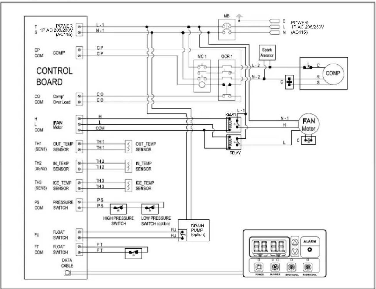
Figure 19 - Circuit Wiring Diagram (Models TC25)
Wiring Diagram
flowchart
graph TD
    subgraph CONTROL BOARD
        T["POWER AC 230V"] --> L1["L-1 N+1"]
        S["DC COM COMP"] --> C.P["C.P"]
        C.P --> MC1["MC-1"]
        MC1 --> OCR1["OCR-1"]
        OCR1 --> L2["L-2 N+2"]
        L2 --> S1["Squam Ancestor"]
        S1 --> C["R COMP"]
        C --> L3["L-3 N+3"]
        L3 --> H["FAN Motor"]
        DQ["Comp Over Load"] --> CQ["C.Q"]
        H["L FAN Motor"] --> H1["H L COM"]
        H1 --> OUT_TEMP["OUT_TEMP SENSOR"]
        OUT_TEMP --> TH1["TH-1 TH-1"]
        OUT_TEMP --> TH2["TH-2 TH-2"]
        OUT_TEMP --> TH3["TH-3 TH-3"]
        OUT_TEMP --> P.S["P-S HIGH PRESSURE SWITCH"]
        OUT_TEMP --> P.S["P-S LOW PRESSURE SWITCH (option)"]
        P.S --> DRAIN["PRAIN PUMP (option)"]
    end

    subgraph CONTROL BOARD
        TH1["OUT_TEMP SENSOR"] --> TH1A["TH-1"]
        TH1A --> TH1B["TH-2"]
        TH1B --> TH2A["TH-3"]
        TH2A --> P.S
        P.S --> DRAIN
        DRAIN --> R2["R2 FLU"]
    end

    subgraph CONTROL BOARD
        TH2["IN_TEMP SENSOR"] --> TH2A["TH-2"]
        TH2A --> TH2B["TH-3"]
        TH2B --> P.S
        P.S --> DRAIN
    end

    subgraph CONTROL BOARD
        TH3["ICE_TEMP SENSOR"] --> TH3A["TH-3"]
        TH3A --> TH3B["TH-3"]
        TH3B --> P.S
    end

    subgraph CONTROL BOARD
        P.S --> DRAIN
    end

    subgraph CONTROL BOARD
        R2 --> DRAIN
    end

    style CONTROL BOARD fill:#f9f,stroke:#333,stroke-width:2px
    style DRAIN fill:#ccf,stroke:#333,stroke-width:2px
    style R2 fill:#cfc,stroke:#333,stroke-width:2px
    style DRAIN fill:#fcc,stroke:#333,stroke-width:2px
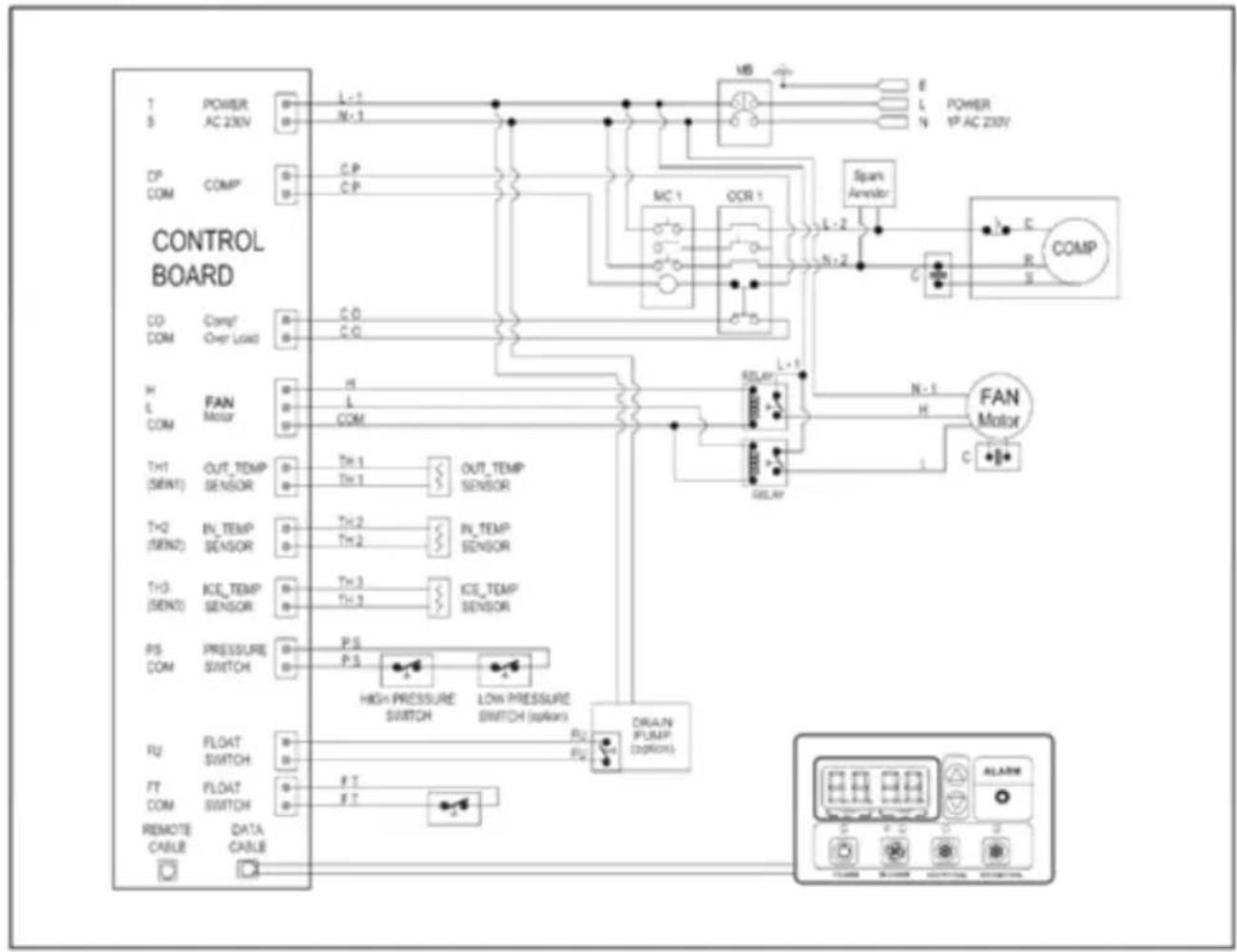
Figure 20 - Circuit Wiring Diagram (Models TC35)
Troubleshooting
| Issues | Possible Cause | Solution |
| The unit does not operate | Has the power cord been disconnected? | Plug the power cord into the socket. Plug in the unit also check power at outlet. |
| Check if the used voltage is lower or higher than the rated voltage? | Check and make sure rated voltage only is supplied and restart the unit. | |
| Is the room temperature above 45°C or below 18°C? | The temperature protection sensor is activated and the unit cannot be started. | |
| Compressor does not start or no air is discharged | Is the air filter clogged? | Clean the air filter as instructed under cleaning section |
| Is the air intake or discharge duct obstructed? | Remove the obstructions | |
| Is the unit tilted or unsteady? | Move the unit to a stable, flat and sturdy location. | |
| Fan not moving | Contact the service center | |
| Operation is noisy | Is the air filter clogged? | Clean the air filter as instructed under cleaning section |
| Water leakage | High water level in condensate tank | Remove blockage from drain hoseRemove any object stuck underneath of the black panel under the water tank |
| Compressor does not start after obstructions are removed and no cold air from cold air outlets | Compressor overload sensor maybe defective | Rest the unit for few hours than restart. Contact the service centre if above fails. |
| Running capacitor maybe defective | Contact the service centre | |
| Compressor will not work if the unit is turned off and on quickly. | Wait for 5 minutes after unit is turned off before turning the unit back on. | |
| The ambient air temperature may be too high | The temperature of the compressor can be higher when the ambient temperature is too high. The compressor will not work unless the ambient air temperature is within the acceptable operating range of the unit | |
| Water flow like noise can be heard after compressor shuts off | No fault | Common to hear coolant flowing after unit shuts off |
| Alarm displays “FT” with less than half of condensate water in the tank Spring is possibly broken | Spring is possibly broken | Replace with a new spring (See Maintenance page 11) |
Note: when the fault cannot be solved by the solutions above, please contact service centre for help, do not attempt repairs.
Technical Data
| Specifications | Unit | TC25 | TC35 |
| Cooling Capacity | BTU/HR | 25,000 | 32,000 |
| Power Supply | PHASE | Single | Single |
| VOLTS | 230V | 230V | |
| HERTZ | 50 | 50 | |
| Size (W x D x H) | mm | 561 x 747 x 1202 | 660 x 885 x 1380 |
| Weight | KG | 106 | 110 |
| Maximum Amperage | AMPS | 12.6 | 16.5 |
| Max power Consumption | KW | 2.7 | 3.3 |
| Air Filter | Cond/Eva | Aluminum / Vinyl chloride | Aluminum / Vinyl chloride |
| Power Cord | TYPE | 250V / 13A | Hard wired / Special 16Amp Inlet |
| Refrigerant | TYPE | R410A | R410A |
| Operating Conditions | °C | 18~45 | 18~45 |
| Hot Air Duct Diameter | mm | 400 | 400 |
| Maximum Duct Length | m | 15 | 15 |
| Safety Devices | Compressor overload protector, Anti-freezing thermistor, Full drain tank switch, Automatic restart on power cut, Compressor protection with time delay program, High pressure switch | ||
| Features | Temperature control, Self-diagnostic function, Two speed fan, Optional drain pump kit, Washable filters, Fahrenheit or Celsius display, off stopping timer | ||
| Operating Range | 18°C-45°C | ||
The unit cannot be operated when room ambient temperature is lower 18^ C as could cause compressor damage.
*Rated capacity was tested under 30°C RH80% test condition.
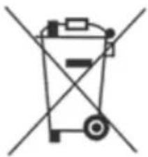
Disposal: Do not dispose this product as unsorted waste. Collection of such waste must be handled separately as special treatment is necessary.
Recycling facilities are now available for all customers at which you can deposit your old electrical products. Customers will be able to take any old electrical equipment to participating sites run by their local councils.
Please remember that this equipment will be further handled during the recycling process, so please be considerate when depositing your equipment. Please contact the local council for details.
Commercial appliances cannot be recycled to domestic recycling centres and must be recycled commercially.
natural_image
Symbol of a trash bin crossed out by two diagonal lines (no text or labels)
All information provided is for reference only. Products specifications may change due to continuous product development. TC25TC35_K17012015_V1
ELECTRIQ UK SUPPORT
Please, for your own convenience, make these simple checks before reading the troubleshooting guide or calling the service line.
- Has the unit been standing upright? (for at least 4 hrs)
- Is the unit plugged into the mains? Is the fuse OK?
- Switch the unit on and wait five minutes to see if the issue is resolved.
- Check whether the water tank is full.
If the unit still fails to operate call: 0871 620 1057 or fill the online form
Office hours: 9AM - 5PM Monday to Friday
www.electr1Quk.com
Unit 2, The Nursery, Berristow Lane, South Normanton, Derbyshire, DE55 2FX
- Contents
- SAFETY INSTRUCTIONS
- Energy Saving and Unit Safety Protection Tips
- Features
- Installation
- To reduce noise levels:
- Assembly and Parts TC25
- POWER CORD HOLDER
- TOP FAN EXHAUST FLANGE
- DISCHARGE DUCTS/SUPPLY AIR DUCT
- AMBIENT AIR ADAPTER (Optional)
- TC35
- COMPONENT PARTS
- PLUGGING IN THE UNIT
- Operation CONTROL PANEL
- Care and Maintenance
- FILTER CLEANING
- Grille and Case Cleaning
- TC25
- Figure 16 - Removing Filters
- SPRING REPLACEMENT (See Figure 18)
- Out of season storage
- Power Cord Maintenance and Replacement
- SELF-DIAGNOSTIC CODES (See Table 1)
- ELECTRIQ UK SUPPORT
Brand : ElectriQ
Model : TC25
Category : Air conditioner