
Combi 80Eco - Central heating boiler Baxi - Free user manual and instructions
Find the device manual for free Combi 80Eco Baxi in PDF.


| Product Type | Gas Fired Wall Mounted Combination Boiler |
| Brand | Baxi |
| Model | Combi 80Eco |
| G.C. Number | 47 075 05 |
| Fuel | Natural Gas |
| Power Supply | 230V ~ 50Hz, 3 Amp fuse |
| Electrical Protection | Must be earthed |
| Heating Mode | Central Heating and Domestic Hot Water (DHW) |
| DHW Priority | Yes – heating interrupts when DHW tap is opened |
| Central Heating Temperature Range | 30°C to 85°C (adjustable) |
| Domestic Hot Water Temperature | Up to 65°C (adjustable) |
| System Pressure (cold) | 0.5 to 1.0 bar |
| Maximum System Pressure | 2.5 bar (safety valve at 3 bar) |
| Safety Devices | Overheat thermostat, flame failure detection, pressure relief valve |
| Flame Failure Reset | Turn selector switch fully anti‑clockwise to ‘R’ position and release |
| Minimum Clearances (Top/Bottom/Sides/Front) | 200mm / 200mm / 5mm / 5mm (450mm for servicing) |
| Installation Standards | BS 6891, BS 5440, BS 5546, BS 7074, BS 5449, BS 6798 |
| Guarantee | 12 months from date of installation for original user |
| Maintenance | Annual service by competent person; wipe outer case with damp cloth only |
| Spare Parts | Available through approved Baxi stockists; quote model and part number |
| Benchmark Log Book | Required for warranty – ensure installer completes sections |
Frequently Asked Questions - Combi 80Eco Baxi
User questions about Combi 80Eco Baxi
0 question about this device. Answer the ones you know or ask your own.
Ask a new question about this device
Download the instructions for your Central heating boiler in PDF format for free! Find your manual Combi 80Eco - Baxi and take your electronic device back in hand. On this page are published all the documents necessary for the use of your device. Combi 80Eco by Baxi.
USER MANUAL Combi 80Eco Baxi
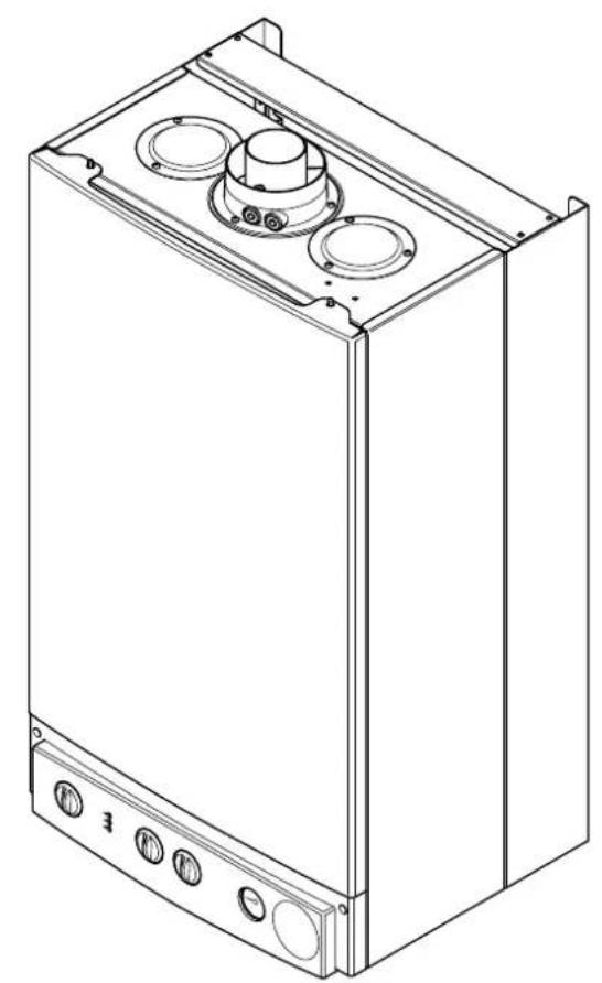
Gas Fired Wall Mounted Combination Boiler
User's Operating Instructions
natural_image
Technical line drawing of a rectangular industrial or electrical cabinet with three circular components and mounting flanges (no text or symbols)BAXI
Natural Gas
Baxi Combi 80Eco
G.C.N° 47 075 05
Where fitted, user label for optional timer to be applied here.
Baxi UK Limited is one of the leading manufacturers of domestic heating products in the UK.
Our first priority is to give a high quality service to our customers. Quality is designed into every Baxi product - products which fulfil the demands and needs of customers, offering choice, efficiency and reliability.
To keep ahead of changing trends, we have made a commitment to develop new ideas using the latest technology - with the aim of continuing to make the products that customers want to buy.
Everyone who works at Baxi has a commitment to quality because we know that satisfied customers mean continued success.
We hope you get a satisfactory service from Baxi. If not, please let us know.
The boiler meets the requirements of Statutory Instrument "The Boiler (Efficiency) Regulations 1993 N° 3083" and is deemed to meet the requirements of Directive 92/42/EEC on the energy efficiency requirements for new hot water boilers fired with liquid or gaseous fuels:-
Type test for purpose of Regulation 5 certified by: Notified Body 0051.
Product/Production certified by: Notified Body 0051.
For GB/IE only.


Baxi is a BS-EN ISO 9001
Accredited Company
| STANDARD | SCOPE |
| B.S. 6891 | Gas Installation. |
| B.S. 5440: Pt 1 | Flues. |
| B.S. 5440: Pt 2 | Air Supply. |
| B.S. 5546 | Installation of hot water supplies for domestic purposes. |
| B.S. 7074 | Expansion vessels and ancillary equipment for sealed water systems. |
| B.S. 5449 | Forced circulation hot water systems. |
| B.S. 6798 | Installation of gas fired hot water boilers. |
"Benchmark" Installation, Commissioning and Service Record Log Book
Please ensure that your installer has completed the Installation and Commissioning sections of the Log Book and hands the Log Book over. The details of the Log Book will be required in the event of any warranty work. Keep the Log Book in a safe place and ensure that the relevant sections are completed at each subsequent regular service visit.
All CORGI registered installers carry a CORGI identification card and have a registration number. Both should be recorded in your boiler Log Book. You can check your installer is registered by telephoning 01256 372300 or writing to:-
1 Elmwood,
Chineham Business Park,
Crockford Lane,
Basingstoke,
RG24 8WG
IN AN EMERGENCY
If a water or gas leak occurs or is suspected, the boiler can be isolated at the inlet valves as follows;
- Turn off the electrical supply and turn the selector switch on the facia box to the OFF position.
- Using a suitable open ended spanner or screwdriver turn the square on the gas tap to the left to isolate the gas supply at the boiler (Fig. 1).
- The isolating valves are positioned under the boiler and can be closed by turning their taps to the right towards the wall (Fig. 2).
- Call your Service Engineer as soon as possible.
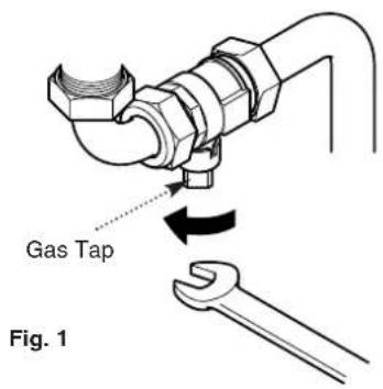
Fig. 2

natural_image
Technical illustration of a pipe fitting with hexagonal nuts and a curved pipe, showing rotational motion (no text or symbols)Heating Flow, Heating
Return and Mains
Water Inlet
Isolating Valves
1.0 Warnings
1.1 Ife Installation
-
The appliance is suitable for installation only in G.B. and I.E. and should be installed in accordance with the rules in force. For Ireland install in accordance with I.S.813 "INSTALLATION OF GAS APPLIANCES". The installation must be carried out by a CORGI Registered Installer or other registered competent person and be in accordance with the relevant requirements of GAS SAFETY (Installation and Use) REGULATIONS most recent edition, the BUILDING REGULATIONS issued by the Department of the Environment, BUILDING STANDARDS (Scotland) (Consolidation) REGULATIONS issued by the Scottish Development Department and the LOCAL BUILDING REGULATIONS. Where no specific instructions are given, reference should be made to the relevant BRITISH STANDARD CODES OF PRACTICE and INSTALLATION SPECIFICATIONS.
-
This appliance must be installed in accordance with the manufacturer's instructions and the rules in force, and only used in a suitably ventilated location.
- Read the instructions before installing or using this appliance.
- Any purpose provided ventilation should be checked periodically to ensure that it is free from obstruction.
IMPORTANT - The addition of anything that may interfere with the normal operation of the appliance without the express written permission of Baxi UK Limited could invalidate the appliance warranty and infringe the GAS SAFETY (Installation and Use) REGULATIONS.
1.2 case of gas leaks
- If a gas leak is found or suspected, turn off the gas supply at the meter immediately and at the isolating valve on the boiler if possible. Contact your Installer or Transco (under 'Gas' in the phone directory).
1.3 Servicing your Appliance
- For reasons of safety and economy your appliance should be serviced annually. Servicing must be performed by a competent person. Your Installer or British Gas Service will be able to advise you.
1.4 Electricity Supply
-
THIS APPLIANCE MUST BE EARTHED.
-
A standard 230V \~ 50Hz supply is required. The appliance must be protected by a 3 amp fuse.
Never Hang Flammable Items Over The Appliance

Fig. 4

2.0 Operating the Boiler
2.1 production
- Your Baxi Combi 80Eco is a gas fired, room sealed, powered flue combination boiler, providing central heating for your home and mains fed domestic hot water to taps and shower. It is fully automatic and does not have a pilot light.
- Priority is given to the hot water mode - when a hot water tap is turned on the supply of heat to the central heating circuit is interrupted.
2.2 Operating the Boiler
- Ensure that the electricity and gas supplies are turned on. Check that the central heating pressure is between 0.5 and 1.0 bar (Fig. 3).
-
Turn the On/Off/Reset selector switch either anti-clockwise from the off position (Fig. 5) to both central heating and domestic hot water or clockwise to domestic hot water only.
-
In either position the green power on neon (Q) will illuminate (Fig. 4).
-
Position (i) In this position the central heating will operate according to demand or provide domestic hot water when a tap or shower is turned on (Fig. 6). Priority is given to domestic hot water.
-
Position (ii) In this position hot water will be provided when a tap or shower is turned on (Fig. 7).
-
The boiler will light automatically on demand.
-
The orange burner on neon ( ) will illuminate when the boiler is operating and the main burner is on (Fig. 4).
IMPORTANT: When the selector switch is in the '0' (Off) position the electrical supply to the boiler is isolated. The boiler will not operate and the integral timer (if fitted) will require resetting once the selector switch is set to either the Position (i) or Position (ii).

Fig. 9
Domestic Hot Water
Temperature Control

2.0 Operating the Boiler
2.3 Temperature Control
- Central Heating: The central heating hot water flow temperature can be adjusted between 30^ C ( ±5^ C) minimum and 85^ C ( ±5^ C) maximum.
- Turn the control knob clockwise to increase the temperature (Fig. 8).
- In normal winter usage we recommend that the central heating temperature be set at maximum.
- Domestic Hot Water: The temperature of the domestic hot water can be adjusted by turning the control knob clockwise to increase up to a maximum of 65^ C (Fig. 9).
- The temperature of the water is also dependent on the water flow rate and the temperature of the mains water coming into the house.
- By slightly reducing the flow from the tap the temperature will increase up to the maximum if required.
- The flow rate can be reduced down to as low as 2.5 litre/min. The boiler will still recognise the need to heat the water.
2.4 fety Thermostat
- Your Baxi Combi 80Eco is fitted with an additional safety device, which shuts down the boiler in the event of the system or the boiler overheating.
- If the device operates, the boiler will shut down. To reset: Contact your Service Engineer - the reset button is inside the appliance and resetting by the user should not be attempted.
- The cause of operation of the safety thermostat should be determined by your Service Engineer.
2.5 Time Failure Reset
- The red flame failure neon ( ) will illuminate in the event of the burner failing to light, or when incomplete lighting of the burner occurs (Fig. 11).
- Turn the selector switch fully anti-clockwise against the spring pressure to the reset position (R) and release (Fig. 10). Set the selector switch to the required position to light the boiler.
- If the flame failure neon illuminates repeatedly a fault is indicated. Your Service Engineer should be contacted as soon as possible.

2.0 Operating the Boiler
2.6 Central Heating System Pressure
- The water pressure in the central heating system is indicated by the pressure gauge.
- With the system cold and the boiler not operating the pressure should be between 0.5 and 1.0 bar. During operation the pressure should not exceed 2.5 bar, and will normally be between 1.0 and 2.0 (Figs. 12 & 13).
- A pressure of 3 or greater indicates a fault. The safety pressure relief valve will operate, at a pressure of 3 (Fig. 14). It is important that your Service Engineer is contacted as soon as possible.
- The minimum pressure for correct operation is 0.5. If the pressure falls below 0.5, this may indicate a leak on the central heating system (Fig. 15).
- The system must be re-pressurised by your Service Engineer.
2.7 Shut Off the Boiler
- For short periods: Turn the selector switch to the Off position (Fig. 16).
- For long periods: Turn off the selector switch (Fig. 16), electricity and gas supplies.
If your home is to be left unoccupied for long periods during cold weather the boiler and whole system should be drained unless equipped with frost protection.
- Your installer will advise you about frost protection and draining the system.
IMPORTANT: When the selector switch is in the '0' (Off) position the electrical supply to the boiler is isolated. The boiler will not operate and the integral timer (if fitted) will require resetting once the selector switch is set to either the Position (i) or Position (ii).

Fig. 17

Fig. 18
3.0 Clearances and Check List
3.1 Clearances around the Boiler
(Figs. 17 & 18)
- The minimum clear spaces needed around the boiler measured from the casing are as follows:
Top - 200mm
Bottom - 200mm
Both sides - 5mm
Front - 5mm (In Operation)
- 450mm (For Servicing)
-
These areas must not be obstructed in any way. Blocking the clearance spaces may result in the boiler overheating and damage may occur.
-
The gas burning compartment of your boiler is completely sealed from the room in which it is fitted. Products from the combustion of gas are vented to the outside through the flue terminal which must be kept free from obstruction as this would interfere with the correct operation of the boiler.
-
The boiler may be installed in a cupboard if these minimum clearances are kept. The compartment should be large enough to house the boiler and ancillary equipment only.
-
IT SHOULD NOT BE USED AS A STORAGE CUPBOARD.
3.2 eck List
-
If a fault develops, or is suspected, call your Service Engineer as soon as possible.
-
Go through the following check list before you make contact.
a) Is the electricity supply on?
b) Is the selector switch on (giving a green "Power ON" light) and set for both Central Heating and Domestic Hot Water?
c) Is the red "Flame Failure" indicator lit? Turn the On/Off/Reset selector fully anti-clockwise.
d) Is the gas supply on?
e) Is the mains water supply turned on?
f) Is the system pressure correct?
g) Are the boiler temperature controls set high enough?
h) Is the time clock (if fitted) calling for central heating?
i) Is the room thermostat (if fitted) set high enough?
j) Are the radiator valves open?

4.0 Cleaning, Spares & Guarantee
4.1 Meaning the Outercase
The painted panels should be wiped with a damp cloth and then dried completely. DO NOT USE ABRASIVE CLEANING AGENTS.
4.2 are Parts
IMPORTANT - Only a competent person should be used to service or repair this boiler.
- Any repairs to the boiler will usually be the responsibility of the Installer during the guarantee period after which spare parts may be obtained through approved Baxi stockists if required.
- Quote the appliance name, model number and where possible the part number when ordering spares. A parts list is included in the Installation and Servicing Instructions.
- The name, model number, and serial number can be found on a label on the inner face of the lower right hand case panel (Fig 19).
4.3 arantee
- Your Baxi Combi 80Eco is designed and produced to meet all the relevant Standards.
- Baxi UK Limited provide a 12 month guarantee on the boiler. The guarantee operates from the date installation is completed for the customer who is the original user.
- To maximise the benefit from our guarantee we urge you to return the reply-paid guarantee registration.
- This does not in any way prejudice your rights at Common Law. Such rights between the customer and the installer or supplier from whom the unit was purchased remain intact.
Any component or part which becomes defective during the guarantee period as a result of faulty workmanship or material whilst in normal use will be repaired or replaced free of charge.
5.0 Notes
5.0 Notes
Baxi UK Limited manufacture a comprehensive range of products for the domestic heating market.
Gas Central Heating Boilers (Wall, Floor and Fireside models).
Independent Gas Fires.
Renewal Firefronts.
Gas Wall Heaters.
Solid Fuel Fires.
If you require information on any of these products, please write, telephone or fax to the Sales Department.
After Sales Service
08706 096 096
BAXI
Baxi UK Limited
Brownedge Road
Bamber Bridge Preston
Lancashire
PR5 6SN
www.baxi.com

- Gas Fired Wall Mounted Combination Boiler
- User's Operating Instructions
- Natural Gas
- "Benchmark" Installation, Commissioning and Service Record Log Book
- IN AN EMERGENCY
- Warnings
- Ife Installation
- case of gas leaks
- Servicing your Appliance
- Electricity Supply
- Operating the Boiler
- production
- Operating the Boiler
- Temperature Control
- fety Thermostat
- Time Failure Reset
- Central Heating System Pressure
- Shut Off the Boiler
- Clearances and Check List
- Clearances around the Boiler
- eck List
- Cleaning, Spares & Guarantee
- Meaning the Outercase
- are Parts
- arantee
- Notes
- After Sales Service
- 096 096
- BAXI
Brand : Baxi
Model : Combi 80Eco
Category : Central heating boiler