
CBP Matic 18 - Central heating boiler Baxi - Free user manual and instructions
Find the device manual for free CBP Matic 18 Baxi in PDF.


| Product Type | Central heating boiler (combi) |
| Brand | Baxi |
| Model | CBP Matic 18 |
| Dimensions (H x W x D) | Approx. 700 x 400 x 300 mm |
| Weight | Approx. 30 kg |
| Power Supply | 230 V / 50 Hz |
| Nominal Heat Output | 18 kW |
| Heating Type | Central heating and domestic hot water |
| Fuel Type | Natural gas or LPG |
| Energy Efficiency Class | C (typical for combi boilers of this era) |
| Operating Pressure | 1-2 bar (recommended) |
| Maximum Flow Temperature | 80 °C |
| Flue Type | Room-sealed (concentric) |
| Installation Type | Wall-mounted |
| Main Functions | Central heating, domestic hot water, frost protection |
| Maintenance and Cleaning | Annual service by a qualified engineer; clean case with damp cloth |
| Safety Features | Flame failure device, overheat thermostat, safety valve |
| Spare Parts Availability | Common parts available through Baxi distributors |
| Reparability Index | 7/10 (modular design, some parts user-replaceable) |
| Noise Level | < 50 dB(A) |
| Warranty | 2 years (typical) |
Frequently Asked Questions - CBP Matic 18 Baxi
User questions about CBP Matic 18 Baxi
0 question about this device. Answer the ones you know or ask your own.
Ask a new question about this device
Download the instructions for your Central heating boiler in PDF format for free! Find your manual CBP Matic 18 - Baxi and take your electronic device back in hand. On this page are published all the documents necessary for the use of your device. CBP Matic 18 by Baxi.
USER MANUAL CBP Matic 18 Baxi
CBP Matic 18, 24 e 30
EN
CBP Matic 18, 24 and 30

natural_image
Exterior view of a white industrial refrigerator with a black vertical panel and control panel (no visible text or symbols)natural_image
Close-up of a hand holding a small metallic coin on a tiled floor (no visible text or symbols)Figura 3 – Pies regulables
natural_image
Close-up of a metallic electrical plug with a cable inserted, showing internal components and a switch (no visible text or symbols)natural_image
Close-up of a metallic ring with a coiled spring on a perforated metal panel (no text or symbols visible)Figura 9 – Sonda de temperatura ambiente
natural_image
Close-up of a mechanical device with wires and a red arrow pointing to a component (no visible text or symbols)a)

natural_image
Close-up of hands connecting cables to a mechanical component with a red arrow pointing to a detail (no visible text or symbols)b)

natural_image
Close-up of a hand holding a small circular object next to cylindrical pipes on a perforated metal surface (no text or symbols visible)c)
natural_image
Close-up of a gloved hand using a tool to inspect or inspect a perforated metal panel, with a magnified view of cylindrical components (no visible text or symbols)natural_image
Black-and-white photo of two workers on a perforated metal surface, one highlighted in red (no visible text or symbols)natural_image
Hand placing a button on a dark metal cabinet (no text or symbols visible)natural_image
Close-up of a gloved hand pressing a small black object on a dark surface, with a red arrow indicating direction (no text or symbols visible)a)

natural_image
Close-up of a metallic appliance with a rectangular lid and open lid, no visible text or symbolsnatural_image
Close-up of a metallic electronic device with a rectangular housing and open lid (no visible text or symbols)natural_image
Close-up of hands using a tool to adjust or install electrical components (no visible text or symbols)a)
natural_image
Close-up of hands holding two small metal probes (no visible text or symbols)b)
natural_image
Close-up of a hand using a power tool to draw or wire (no text or symbols visible)c)
natural_image
Close-up of a hand holding a small electronic component (no visible text or symbols)d)

natural_image
Close-up of a metallic door with a rectangular panel and a white arrow pointing to a detail (no text or symbols visible)e)
natural_image
Two identical yellow rectangular blocks with black square tops and curved lines, no text or symbols present.natural_image
Close-up of a black electronic device mounted on a yellow PCB with wires and a red arrow pointing to it (no visible text or symbols)a) b)

a)
natural_image
Close-up of a hand inserting a black plug into a white wall socket (no text or symbols visible)b)
natural_image
Close-up of a hand holding a white electronic device with black circuit lines and a small black component (no visible text or symbols)d)

natural_image
Hand holding a black 3D object against a white background with grid patterns (no text or symbols visible)natural_image
3D technical diagram of a mechanical assembly with no visible text or symbolsnatural_image
Exterior view of a white rectangular electronic device with a black cable and a small component, placed on a textured surface (no text or symbols visible)natural_image
Hand holding a small electronic component with wires, placed on a white panel with a wooden bolt base (no text or symbols visible)a) b)
natural_image
Hand holding a small electronic component with a red arrow pointing to it, placed on a white panel with wooden blocks in the background (no text or symbols visible)
natural_image
Close-up of a small electronic device mounted on a white panel with a black box and cable, placed on a textured surface (no visible text or symbols)natural_image
Hand holding a small electronic device mounted on a white base with green circuit board, placed on a textured surface (no text or symbols visible)a) b)

natural_image
Hand holding a small electronic device mounted on a white base with a green panel, placed on a woven mat (no text or symbols visible)natural_image
3D mechanical assembly diagram showing a component with highlighted section and red arrow (no text or symbols)natural_image
3D diagram of an industrial machine with internal components and a red arrow indicating direction (no text or symbols)a)
natural_image
Hand inserting a cable into a black rectangular device with red cables, no visible text or symbolsb)

natural_image
Close-up of hands using a handheld device to adjust or install a black mechanical component with red wires (no visible text or symbols)c)

natural_image
Close-up of a mechanical component with a black flange and coiled tubing (no visible text or symbols)natural_image
Technical diagram of a pipe joint with a red dashed line indicating a dimension (no text or symbols present)a)

natural_image
3D mechanical part diagram with a red dashed line indicating a reference axis (no text or symbols)natural_image
Hand holding a transparent plastic hose attached to a black door handle (no text or symbols visible)a) b)
natural_image
Person installing or adjusting a wall-mounted cable or hose component (no visible text or symbols)
natural_image
Close-up of a metallic threaded screw fastener attached to a dark panel (no text or symbols visible)c) d)

natural_image
Close-up of a transparent plastic hose with red dashed alignment lines, no visible text or symbolsnatural_image
3D diagram of an open industrial refrigerator with red arrows indicating internal components (no text or symbols)a)
natural_image
Close-up of a hand holding a coiled metal hose attached to a black industrial component, with wiring visible (no text or symbols)b)

natural_image
Close-up of a mechanical component with coiled spring and red arrow indicator (no visible text or symbols)natural_image
Technical illustration of two mechanical components with green plastic parts and red arrows indicating motion or assembly (no text or symbols)natural_image
Technical illustration of a kitchen cabinet with highlighted internal components and directional arrows indicating movement (no text or symbols present)natural_image
Isometric line drawing of a cabinet with an open lid and internal components (no text or symbols)natural_image
Isometric line drawing of a cabinet with internal door and door, showing a horizontal double-headed arrow indicating direction (no text or symbols)a) b)

natural_image
3D line drawing of a cabinet with an open lid and a red arrow indicating rotation (no text or symbols)
natural_image
Isometric line drawing of a cabinet or enclosure with a red arrow indicating a component, no text or symbols present.c) d)

natural_image
Isometric line drawing of a cabinet with an open lid and internal components (no text or symbols)natural_image
3D diagram of a cabinet with internal components and colored panels (no text or symbols)a) b)

natural_image
3D line drawing of a cabinet with a green handle and black interior (no text or symbols)natural_image
3D mechanical assembly diagram showing internal components and housing (no text or symbols)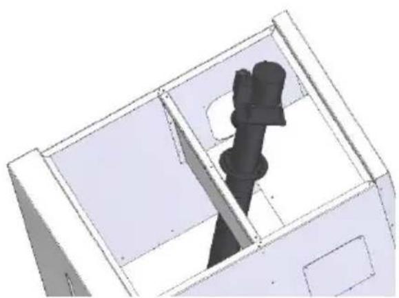
natural_image
3D technical drawing of a mechanical component with internal structure (no text or symbols)natural_image
Technical diagram showing a mechanical assembly inside a container with directional arrows indicating motion (no text or symbols present)a) b)

natural_image
Technical illustration of a mechanical component with a red dashed line indicating a cutting or dissection (no text or symbols present)natural_image
3D architectural rendering of a building interior with a green arrow indicating a component (no text or symbols)c)
natural_image
Technical diagram showing a pipe assembly inside a container with a side view of a mechanical component (no text or symbols visible)d) e)
natural_image
3D rendered mechanical component with a red dashed line indicating a dimension (no text or symbols)natural_image
Two technical diagrams showing a component assembly with highlighted parts and a red arrow indicating a specific section (no text or symbols present)natural_image
Two technical diagrams showing a device with a yellow square component and a black square inside, both without any text or symbols.natural_image
3D architectural diagram showing a structural component with a red arrow indicating direction (no text or symbols present)a) b)
natural_image
3D architectural diagram showing a vehicle inside a building with a red arrow indicating direction (no text or symbols)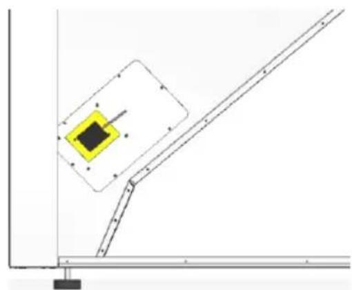
natural_image
Pure technical diagram showing a mechanical assembly with no text, numbers, or symbolsnatural_image
3D diagram of a mechanical device with a green component and red arrow indicating direction (no text or symbols)
natural_image
3D diagram of a cabinet with green doors and red arrows indicating directional movement (no text or symbols)natural_image
Hand holding a transparent plastic hose attached to a black door handle (no text or symbols visible)a) b)

natural_image
Close-up of hands using a red tool to handle a metallic cylindrical component (no visible text or symbols)
natural_image
Close-up of a metallic threaded pipe attached to a black metal bracket (no text or symbols visible)c) d)

natural_image
Close-up of a metallic cylindrical component with red dashed alignment lines, no visible text or symbolsnatural_image
Hand inserting a small white object into a wall-mounted device (no visible text or symbols)a)

natural_image
Hand inserting a black plug into a wall socket (no text or symbols visible)b)

natural_image
Close-up of a hand interacting with a white electronic device panel, showing wiring and a black control panel (no visible text or symbols)d)

natural_image
Hand holding a black 3D cube-shaped object against a white background with grid patterns (no text or symbols visible)natural_image
3D diagram of a refrigerator interior showing internal compartments and doorways (no text or labels)a) b)
natural_image
Close-up of a hand holding a coiled metal hose attached to a mechanical component (no visible text or symbols)
natural_image
Close-up of a hand adjusting a flexible hose component with red arrows pointing to the pipe (no visible text or symbols)natural_image
3D diagram of a room corner with a green panel and red arrows indicating directional flow or movement (no text or symbols)
natural_image
3D rendering of a cabinet or cabinet with a green-labeled component, no visible text or symbolsnatural_image
3D technical diagram showing internal components and alignment of a device with red arrows indicating motion or force, no text or symbols present.natural_image
Isometric line drawing of a cabinet with an open lid and internal components (no text or symbols)natural_image
Top-down view of a mechanical assembly or mounting bracket with no visible text or symbolsa)
natural_image
Close-up of hands operating a mechanical device with wires and components (no visible text or symbols)natural_image
Close-up of a dark rectangular electronic component with metallic pins, partially enclosed by a metal frame (no visible text or symbols)
natural_image
Close-up of a hand holding a metal bracket with a tool, against a cloudy sky background (no text or symbols visible)natural_image
Black and white photo of a robotic arm on a dark surface, with no visible text or symbolsa)

natural_image
Close-up of a gloved hand pressing down on a mechanical component (no visible text or symbols)b)
natural_image
Close-up of hands installing or adjusting a mechanical device into a dark tray (no visible text or symbols)c)

natural_image
Close-up of a hand using a tool to adjust or install electronic components in a device (no visible text or symbols)d)

natural_image
Close-up of a metal frame with circular components and metal rods, no visible text or symbolse)

natural_image
Close-up of a hand adjusting a metal bracket with multiple circular components (no visible text or symbols)f)

natural_image
Close-up of a mechanical device with coiled spring-like components and a hand operating it (no visible text or symbols)g)
natural_image
Interior view of a mechanical or industrial mold cavity with circular cavities and a cylindrical pin (no visible text or symbols)natural_image
Close-up of a gloved hand using tweezers to test a metal ingot on a stovetop (no visible text or symbols)a)
natural_image
Close-up of a hand using a tool to clean or store contents on a circular metal plate (no visible text or symbols)b)

natural_image
Close-up of a mechanical component with a rectangular cutout and mounting holes (no visible text or symbols)c)
natural_image
Dark rectangular object with faint internal patterns, possibly a patterned surface or abstract design (no text or symbols visible)natural_image
Close-up of a metal panel with a red circle highlighting a bolt detail (no text or symbols visible)a)

natural_image
Close-up of a mechanical component with a red-circled hole and bolted joints (no visible text or symbols)b)
natural_image
Close-up of a metallic mechanical component with a central hub and mounting base (no visible text or symbols)
natural_image
Exterior view of a rectangular concrete block with a circular hole and a central hole, under dim lighting (no text or symbols visible)- El cronotermostato debe tener 1º a 2 °C de hysterisis.
- Hidro independiente "On" (water temperatura controlled regulation)
- Modulating pump "On"
- Water sensing inhibition "On"
- Alternative hydro shutdown "On"
- Bomba "On" = 50 °C
- Bomba "Off" = 50 °C
natural_image
Close-up of a hand holding a black plastic object with a metallic knob, against a plain tiled floor (no text or symbols visible)natural_image
Close-up of a metallic electrical outlet plug with a cable inserted, showing no visible text or symbols.natural_image
Close-up of a metallic ring knocker mounted on a perforated metal wall (no text or symbols visible)Figura 9 – Sonda de temperatura ambiente
natural_image
Close-up of a mechanical device with wires and a red arrow pointing to a component (no visible text or symbols)b)

natural_image
Close-up of hands connecting cables to a mechanical component with a red arrow pointing to a detail (no visible text or symbols)b)

natural_image
Close-up of a hand adjusting a cylindrical component with a red arrow pointing to it (no visible text or symbols)c)

natural_image
Close-up of a hand using a tool to inspect or inspect a cylindrical mechanical component (no visible text or symbols)d)
Figura 10 – Motor linear de limpeza
natural_image
Black-and-white photo of a perforated metal wall with two circular insets showing a mechanical component (no text or symbols visible)Figura 11 – Motor linear de limpeza
7. Comando
7.1. Comando e display

Figura 12 – Comando e display

natural_image
Hand placing a dark gray door panel with a white handle, no visible text or symbolsnatural_image
Close-up of a gloved hand pressing a small black object on a dark surface, with a red arrow indicating direction (no text or symbols visible)a)

natural_image
Close-up of a stainless steel kitchen appliance with a square lid and open lid (no visible text or symbols)b)
Figura 15 – Abertura da tampa
natural_image
Close-up of a metallic tray with a rounded square opening, mounted on a base (no visible text or symbols)natural_image
Two electronic devices: a digital thermometer displaying 13.5°C and a white thermometer with a digital display showing 2.102 (no visible text or symbols on main components)a)
b)


natural_image
Close-up of hands using a tool to adjust or install a mechanical component (no visible text or symbols)a)
natural_image
Close-up of hands holding two thin wires or wires with a small object nearby (no visible text or symbols)b)

natural_image
Close-up of a hand holding a small tool with wires, no visible text or symbolsc)
natural_image
Close-up of a hand holding a small electronic component (no visible text or symbols)d)

natural_image
Close-up of a metallic electrical cabinet with a rectangular panel and a white arrow pointing to a button (no text or symbols visible)e)
natural_image
Close-up of a hand holding an electronic device with labeled ports (JA, JB, JC) and cable connectors (no readable text beyond labels)
natural_image
Two identical yellow rectangular blocks with black rectangular elements and curved lines, no text or symbols present.natural_image
Close-up of a yellow electronic device with a black sensor or probe mounted on a blue panel, showing wiring and a red arrow pointing to the component (no readable text or symbols)a) b)
natural_image
Hand inserting a black plug into a wall socket (no text or symbols visible)b)
natural_image
Close-up of a hand interacting with a white electronic device panel, showing a grid pattern and wiring (no visible text or symbols)d)
natural_image
Close-up of a hand holding a black rectangular object against a white background with grid patterns (no visible text or symbols)natural_image
3D architectural rendering of a building interior with structural elements and a red arrow indicating direction (no text or symbols)natural_image
Exterior view of a small electronic device mounted on a white rectangular base with a black cable, placed on a textured surface (no text or symbols visible)natural_image
Hand holding a small black component mounted on a white panel with a red arrow pointing to it, against a textured surface (no text or symbols visible)a) b)

natural_image
Hand holding a small electronic component with a red arrow pointing to it, placed on a white panel with a wooden bolt and screw base (no text or symbols visible)
natural_image
Close-up of a small electronic device with a black box and red arrow pointing to it, placed on a textured surface (no text or symbols visible)natural_image
Hand inserting a small electronic device into a white plastic-wrapped plate on a textured surface (no text or symbols visible)a) b)

natural_image
Hand inserting a small electronic component into a white plastic housing on a woven mat (no text or symbols visible)natural_image
3D architectural diagram showing a room with a window, ceiling, and wall-mounted equipment (no text or symbols visible)a) b)
natural_image
Technical line drawing of a mechanical assembly with a highlighted square component (no text or symbols)natural_image
3D mechanical assembly diagram showing a component with highlighted section and red arrow (no text or symbols)natural_image
Hand holding a transparent plastic hose attached to a black door handle (no text or symbols visible)a) b)
natural_image
Person in plaid shirt using a red tool to install or install a black wall panel (no visible text or symbols)
natural_image
Close-up of a metallic screw fastener inserted into a black wall corner (no text or symbols visible)
natural_image
Close-up of a metallic coiled hose with red dashed alignment lines (no text or symbols)natural_image
3D diagram of an open refrigerator with red arrows indicating internal components (no text or symbols)a)
natural_image
Close-up of a hand holding a coiled metallic pipe attached to a black industrial component with red wires (no visible text or symbols)b)

natural_image
Close-up of a mechanical component with red arrows pointing to a cylindrical assembly (no visible text or symbols)natural_image
3D diagram of a structural joint with green components and red arrows indicating direction (no text or symbols)a) b)

natural_image
3D diagram of a cabinet or enclosure with a green-labeled component, no visible text or symbolsnatural_image
3D architectural diagram of a cabinet interior with highlighted door and red circular annotation (no text or symbols)natural_image
3D diagram of a cabinet with an open lid and internal components, showing a red arrow indicating downward motion (no text or symbols)natural_image
3D diagram of a mechanical housing with green panel and red arrows indicating components (no text or symbols)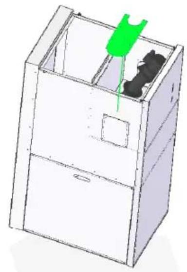
natural_image
3D line drawing of a cabinet with a green handle and black interior (no text or symbols)natural_image
3D mechanical assembly diagram showing a piston and cylinder inside a housing (no text or symbols)a) b)

natural_image
3D diagram of a mechanical component with directional arrows indicating rotation or movement (no text or symbols)natural_image
Technical diagram showing a mechanical assembly inside a container with directional arrows indicating motion (no text or symbols present)a) b)
natural_image
3D rendering of a mechanical component with a curved internal structure and red dashed line indicating a dimension (no text or symbols)natural_image
3D CAD model of a mechanical assembly with highlighted components and directional arrows (no text or symbols)c)
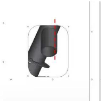
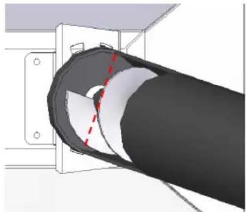
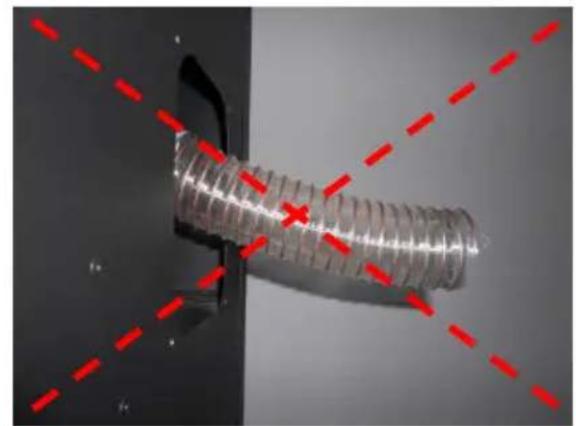
No final, a saída de pellets deverá estar perpendicular à lateral do silo.

natural_image
Technical diagram of a mechanical assembly inside a transparent enclosure, showing internal components and alignment lines (no text or symbols)d) e)

natural_image
3D rendered mechanical part with a red dashed line indicating a dimension or reference (no text or symbols)natural_image
Two technical diagrams showing a device assembly with highlighted components and a red arrow indicating a specific section (no text or symbols present)natural_image
Two technical diagrams showing a yellow square component with black center and red upward arrow, mounted on a flat plate (no text or symbols)natural_image
3D line drawing of a cabinet with internal components and a green arrow indicating direction (no text or symbols)a) b)

natural_image
3D diagram of a cabinet with green doors and red arrows indicating directional movement (no text or symbols)natural_image
Hand holding a flexible hose attached to a black door handle (no text or symbols visible)a) b)

natural_image
Close-up of hands using a red tool to handle a coiled metal pipe or hose (no text or symbols visible)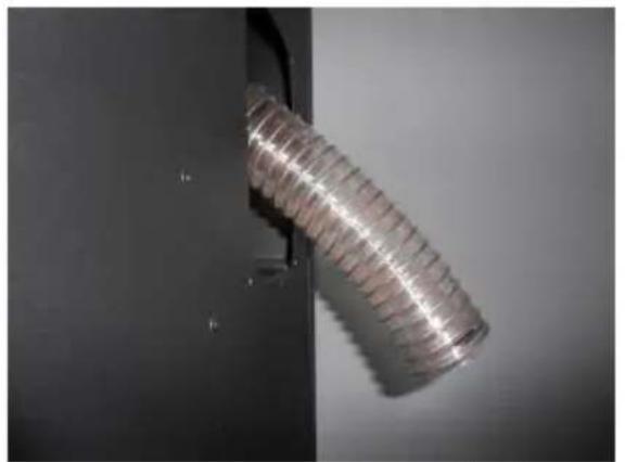
natural_image
Close-up of a coiled metallic wire or filament mounted on a black metal bracket (no text or symbols visible)c) d)
natural_image
Close-up of a metallic threaded component mounted on a black surface, with red dashed lines and a cross mark indicating alignment or measurement (no text or symbols present)natural_image
Hand inserting a small white object into a wall, no visible text or symbolsa)

natural_image
Hand inserting a black plastic plug into a wall socket (no text or symbols visible)b)

natural_image
Close-up of a hand holding a small electronic device with a grid of black rectangular components and wires (no visible text or symbols)d)

natural_image
Close-up of a hand holding a black rectangular object against a white background with grid patterns (no visible text or symbols)natural_image
3D diagram of a refrigerator with open door and internal compartments, showing red arrows indicating movement or force (no text or symbols)a)

natural_image
Close-up of a hand adjusting a coiled metal hose component with a red arrow pointing to the pipe (no visible text or symbols)b)

natural_image
Close-up of a hand adjusting a flexible hose component with red arrows indicating direction (no text or symbols visible)natural_image
3D diagram of a room corner with a green component and red arrows indicating direction (no text or symbols)a) b)
natural_image
3D rendering of a mechanical bracket with a green-labeled component (no text or symbols visible)natural_image
3D architectural diagram showing a cabinet interior with red arrows indicating movement, and close-ups of green indicator lights on the floor (no text or symbols)natural_image
3D technical illustration of a cabinet with an open lid and internal components, showing no text or symbols.natural_image
Top-down view of a mechanical component with visible structural elements and mounting holes (no text or symbols)a)
natural_image
Close-up of hands using a tool to adjust or install electronic components on a circuit board (no visible text or symbols)natural_image
Close-up of a dark rectangular electronic component being held by a hand, with no visible text or symbols.
natural_image
Close-up of a hand using a tool to adjust or install a metal bracket (no visible text or symbols)Figura 54 – Porta inferior e gaveta de cinzas
natural_image
Close-up of a white hand resting on a dark surface, possibly a robotic arm or tool, with no visible text or symbols.b)

natural_image
Close-up of a robotic arm interacting with a mechanical device (no visible text or symbols)b)
natural_image
Close-up of hands installing or adjusting a mechanical component on an open device (no visible text or symbols)c)

natural_image
Close-up of a hand using a tool to adjust or install electronic components in a device (no visible text or symbols)d)
natural_image
Close-up of a mechanical or electrical component with multiple circular components and metal rods (no visible text or symbols)e)

natural_image
Close-up of a hand holding a small object over a grid of circular components (no visible text or symbols)f)

natural_image
Close-up of a mechanical device with coiled springs and a hand adjusting it (no visible text or symbols)g)
natural_image
Interior view of a mechanical or industrial device with circular cavities and a cylindrical component (no visible text or symbols)h)
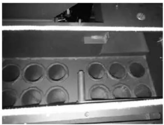
Figura 55 – Limpeza dos canais de passagem de ar e turbuladores.
Limpeza Queimador
natural_image
Close-up of a gloved hand holding a small transparent object over a perforated metal tray (no visible text or symbols)a)
natural_image
Close-up of a hand using a tool to clean or store contents on a circular metal object (no visible text or symbols)b)

natural_image
Close-up of a mechanical component with a rectangular opening and mounting holes (no visible text or symbols)c)

natural_image
Top-down view of a dark rectangular object with faint internal patterns and two chopsticks placed beside it (no text or symbols visible)d)
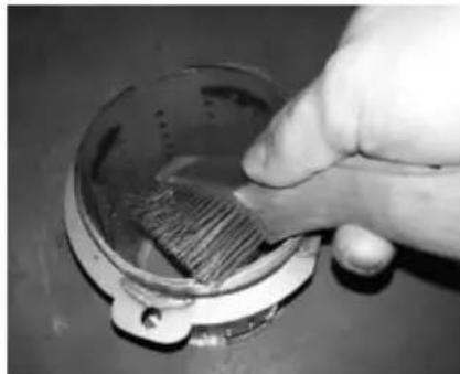
Figura 56 - Limpeza do queimador e do prato de limpeza.
natural_image
Close-up of a metal bracket with a red circle highlighting a detail on the side panel (no text or symbols visible)b)

natural_image
Close-up of a mechanical component with a red circle highlighting a small circular feature (no text or symbols visible)natural_image
Close-up of a mechanical device with a central circular component and mounting brackets (no visible text or symbols)
natural_image
Close-up of a mechanical component with a circular cutout and mounting base (no visible text or symbols)flowchart
graph TD
    A["Input Material"] --> B["Reactor Unit"]
    B --> C{Valve}
    C -->|T0| D["Process Unit 1"]
    C -->|N| E["Output Unit 2"]
    D --> F["Reactor Unit 3"]
    F --> G["Output Unit 4"]
    G --> H["Reactor Unit 5"]
    H --> I["Output Unit 6"]
    I --> J["Reactor Unit 7"]
    J --> K["Output Unit 8"]
    K --> L["Reactor Unit 9"]
    L --> M["Output Unit 10"]
    M --> N["Reactor Unit 11"]
    N --> O["Output Unit 12"]
    O --> P["Reactor Unit 13"]
    P --> Q["Output Unit 14"]
    Q --> R["Reactor Unit 15"]
    R --> S["Output Unit 16"]
    S --> T["Reactor Unit 17"]
    T --> U["Output Unit 18"]
    U --> V["Reactor Unit 19"]
    V --> W["Output Unit 20"]
    W --> X["Reactor Unit 21"]
    X --> Y["Output Unit 22"]
    Y --> Z["Reactor Unit 23"]
    Z --> AA["Output Unit 24"]
    AA --> AB["Reactor Unit 25"]
    AB --> AC["Output Unit 26"]
    AC --> AD["Reactor Unit 27"]
    AD --> AE["Output Unit 28"]
    AE --> AF["Reactor Unit 29"]
    AF --> AG["Output Unit 30"]
Please read this manual carefully and retain it for future reference.
* All products here detailed meet the requirements of the EU Construction Products Regulation (Reg. No. 305/2011) and meet EC; conformity approval.
* The pellet-run boilers are manufactured in compliance with European standard EN 303-5:2012.
* BAXI is not responsible for any damage to units installed by non-qualified personnel;
* BAXI is not responsible for any damage to units not installed and used in compliance to the instructions included in this manual;
* All local regulations, including but not limited to national and European standards, must be observed when installing, operating and servicing the unit.
Contents
- Package content....3
- Safety precautions ⚠️ …… 3
- Technical specifications....6
- Installation of the pellet-run boiler 8
- Installation requirements 9
- Hydraulic Installation.... 14
- Fuel.... 15
- Use of the pellet-run boiler.... 16
- Installation of the external silo.... 41
- Maintenance ⚠......66
- Alarms / failures / recommendation list ▲ 71
- Installation Diagrams....73
- Electrical diagram of the pellet-run boiler 77
- Performance graph for the UPM3 25-70 (130 mm) circulating pump ..... 79
- Life cycle of a pellet-run boiler 80
- Glossary 80
1. Package content
BAXI ships the unit with the following components:
- CBP MATIC Boiler (18 kW or 24 kW or 30 kW);
- Instruction manual;
- Power cable;
- Linear cleaning motor arm protection.
1.1. Unpacking the Boiler
To unpack the unit, first remove the retractable bag covering the cardboard box. Then, lift out the cardboard box and remove the bag containing the boiler and the styrofoam blocks. Finally, unscrew the four parts securing the unit to the wood pallet.
2. Safety precautions

Solzaima is not liable for any damages to the unit if the specified precautions, warnings and operating procedures are not followed.
Units manufactured by Solzaima are easy to operate and special attention was given to their components in order to protect users and installers against accidental damages.
The units must only be installed by an authorised engineer, who should supply the client with a relevant statement of conformity and who shall be liable for the final installation and consequent product good operating conditions.
This unit must be used according to its intended use as specified by the manufacturer. The manufacturer is excluded from all liability, by contract or by tort, caused by injury to people, animals or property arising from misuse or faulty installation or servicing.
After removing the packaging, verify the contents to check its integrity and completeness. If the package contents does not correspond to the parts list specified on item 1, please contact the entity from whom you purchased the unit.
All the unit's components guarantee its operation and energy efficiency and should only be replaced with original parts provided by an authorised technical assistance centre
The unit must be serviced at least once a year by the installation engineer.
This manual is provided with the product. Please keep it beside the unit.
For your safety, we recommend that:
- You fully read and understand the information detailed in this manual before handling the pellet-run boiler, which is a biomass heating unit.
- You make sure the hydraulic circuit was correctly assembled and connected to the water supply before turning on the pellet-run boiler.
- The boiler is not intended for use by children or persons with limited physical, sensory or mental capabilities, nor by those lacking experience and knowledge, unless under direct supervision or instruction.
- Do not touch the boiler when barefoot, nor when any part of your body is wet or humid.
- Do not tamper with safety or adjustment features without the manufacturer's authorization;
- Do not cover or reduce the size of the vents at the installation area;
- The pellet-run boiler requires good air supply to guarantee correct combustion; as such, if the unit is kept in an air tight environment or is exposed to other existing sources of air extraction, its correct functioning may be impeded.
- The existence of vents is a requisite for proper combustion;
- Do not leave the packing materials near children;
- When the unit is operating normally, the boiler door cannot be opened.
- Avoid direct contact with parts of the unit that tend to become hot during operation;
- Check the existence of any obstructions on the fume duct before turning on the unit after a long period of inactivity;
- This pellet-run boiler is intended for residential use, within a protected environment. Safety systems may intervene to shut down the boiler. If this occurs,
contact technical assistance. In any circumstances should you attempt to interfere with the safety systems;
- The pellet-run boiler is a biomass heating unit equipped with an electric fume extractor. The occurrence of any power failure during its use may prevent fume extraction and the room will be filled with smoke. For this reason, you should have a natural fume extraction system, like a chimney, available;
- Solzaima offers an optional safety system that allows you to connect your boiler to a UPS unit, thus avoiding problems related to a power failure and ensuring that the fume extractor will continue to operate under such conditions until the complete extraction of all fumes;
- If you intend to use your boiler when leaving it unattended or while you are away from home, it is advised that you utilise the safety system specified above to guarantee its safe functioning in the eventuality of a power failure;
-
While in operation, NEVER disconnect the electric plug of your pellet-run boiler. Seeing as the boiler's fume extractor is power-operated, disconnecting the plug would prevent the extraction of combustion fumes;
-
Your unit must be disconnected from the mains for servicing. Before doing this, the unit must be totally cooled down (if operating before);
- Never touch the interior of the boiler without first disconnecting it from the power mains;
- The maximum water temperature (set-point temperature) that the user can set for the boiler is 80°C. In the event of the boiler reaching a temperature of 95°C, it will automatically switch off and activate a corresponding alarm.
3. Technical specifications
| FEATURES | CBP Boiler 18 kW | CBP Boiler 24 kW | CBP Boiler 30kW | Units |
| Weight | 350 | 350 | 350 | Kg |
| Height | 1300 | 1300 | 1300 | mm |
| Width | 677 | 677 | 677 | mm |
| Depth | 1110 | 1110 | 1110 | mm |
| Diameter of the fume discharge pipe | 100 | 100 | 100 | mm |
| Reservoir capacity | 45 | 45 | 45 | Kg |
| Maximum heating capacity | 425 | 545 | 680 | |
| Maximum thermal power (water) | 18 | 24 | 29 | kW |
| Minimum thermal power (water) | 6 | 6 | 6 | kW |
| Minimum fuel consumption | 1.3 | 1.3 | 1.3 | Kg/h |
| Maximum fuel consumption | 4.4 | 5.3 | 6,1 | Kg/h |
| Rated electrical current | 150 | 150 | 150 | W |
| Electric power at start-up (<10 min.) | 450 | 450 | 450 | W |
| Rated voltage | 230 | 230 | 230 | V |
| Nominal frequency | 50 | 50 | 50 | Hz |
| Thermal yield at rated thermal power | 90 | 90.2 | 90.4 | % |
| Thermal yield at reduced thermal power | 87,8 | 87,8 | 87,8 | % |
| Max. gas temperature | 102,4 | 112 | 121.6 | °C |
| Min. gas temperature | 74.1 | 74.1 | 74.1 | °C |
| CO emissions at rated thermal power | 0.010 | 0.015 | 0.019 | % |
| CO emissions at reduced thermal power | 0.026 | 0.026 | 0.026 | % |
| Draught in the chimney | 12 | 12 | 12 | Pa |
| Unit water volume | 60 | 60 | 60 | W |
| Fume extractor sound level | 67,6 | 67,6 | 67,6 | dB(A) |
Table 4 – Technical specifications
Tests performed using wood pellets with a heating capacity of 4.9 kWh/kg.
The above information was obtained during product homologation tests performed at independent laboratories accredited for pellet unit tests.
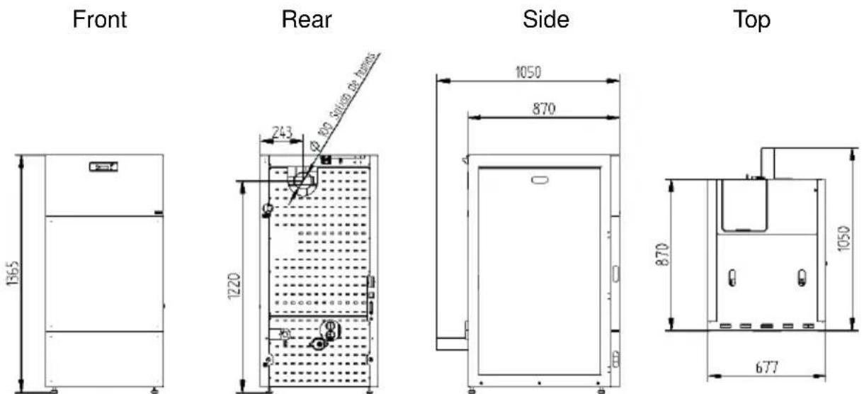
Figure 1 – Dimensions of automatic pellet-run boiler.

Figure 2 – Hydraulic connections of the automatic pellet-run boiler.
4. Installation of the pellet-run boiler
Before installing, please perform the following steps:
- Upon reception, check the product for completeness and to determine that is does not show any damage signs. Any damages or defects should be checked before the unit is installed.
- The unit is equipped with four height adjustable feet at its base, allowing for simple adjustments when installing on non-flat surfaces.

natural_image
Close-up of a hand holding a small circular object on a tiled floor (no visible text or symbols)Figure 3 – Adjustable feet
- Remove the instruction manual from the package and hand it over to the client.
- Connect a 100 mm diameter pipe between the boiler's combustion gases output and the fume extraction pipe leading out of the building (e.g. through the chimney) – please check diagrams in point 4.
- If a tube is used for combustion air inlet from the outside, it shall be no longer than 60cm horizontally or present offsets (such as bends);
- Carry out the hydraulic installation (please consult point 4.5)
- Connectthe 230 VAC power cable to an grounded socket.
- The unit's remote control has a programmable thermostat. Optionally, a conventional external programmer may be used (not included) to automatically define the unit's operating periods.
3.1 Installation requirements
The minimum distance required between the pellet-run boiler and any highly flammable surfaces is found specified in 4.
The top of the boiler must be at a distance of at least 100 cms from the ceiling, especially in rooms with ceilings composed of flammable materials.
The base supporting the boiler cannot be of flammable material. As such, adequate protection should always be used.

Figure 4 – Minimum distances from all surfaces: a) upper view of the unit's installation; b) side view of the unit's installation

Warning!
Keep combustible and flammable materials at a safe distance.
4.2. Installation of pipes and fume exhaust systems:
- The exhaust pipe must have been designed for this purpose, in compliance to the location requirements and in accordance with any applicable regulations.
- Important! An inspection-"T", fitted with a hermetic lid, must be attached to the end of the boiler's exhaust pipe to allow for the regular inspection of the system, as well as the discharge of heavy dust and condensates.
- As indicated in Figure 4, the exhaust duct must be assembled so as to permit its cleaning and maintenance through the inspection points.
- Under normal operating conditions, the combustion gas flow should create a draught of 12 Pa one meter above the chimney neck.
- The boiler must not share the chimney with any other equipment.
- The pipes located outside the boiler's working area must have an internal diameter of 100 mm and be of double stainless steel insulation.
- The fume exhaust pipe may generate condensation, so we recommend that the appropriate systems for collecting condensates should be installed.
4.3. Installation without a shaft
Figure 5 and 6 illustrate the basic requirements when installing the boiler's chimney. A "T" should be included at the base of the piping system for the purpose of periodic inspections and annual maintenance, as exemplified. Double-walled stainless steel insulated pipes must be used and properly fastened to avoid condensation.
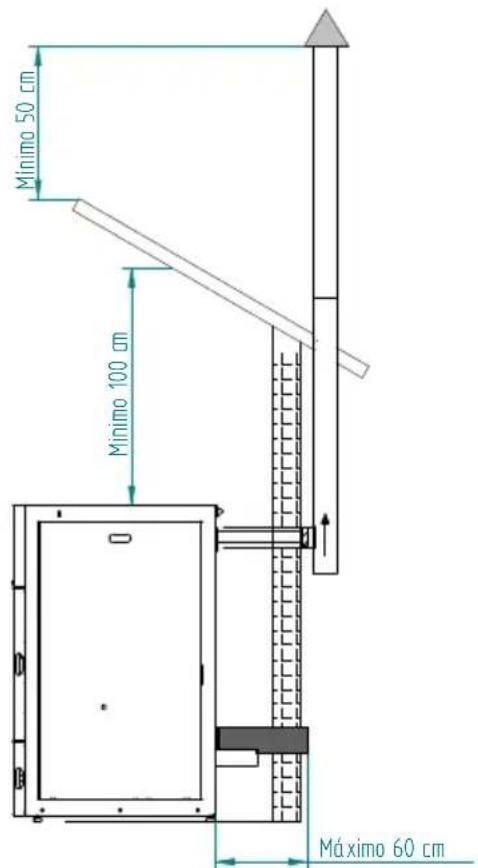
Figure 5 – Side view of the boiler installation without a shaft, highlighting the inspection point.

c)
Figure 6 – Examples of standard installations.
⚠️ Failure to comply with the requirements here detailed may prevent the correct operation of the unit. Follow all the instructions presented on the diagrams.
The boilers operate with the combustion chamber in depression, which is why it is absolutely necessary that they include a fume exhaust pipe to adequately extract combustion gases.
Fume duct material: The tubing must consist of 0.5 mm thick rigid stainless steel, with fastening joints attaching the different sections and accessories.
Insulation: The fume ducts must be double-walled and insulated to make sure that fumes do not cool down going outwards, which would cause an inadequate circulation and condensation that may damage the unit.
Output "T-tube": Always attach a regulator "T-tube" to the output of the boiler.
Windproof terminal: A windproof terminal must always be installed to avoid the backflow of fumes.
Chimney draught: The figures below show three standard diagrams, specifying adequate lengths and diameters. Any other type of installation must guarantee a draught of 12 Pa (0.12mbars) measured when hot and at the maximum power.
Ventilation: To ensure the boiler's optimum operation, the installation location should be fitted with an air vent, with a minimum cross-section of 100 cm preferably close to the unit's back panel. The boiler includes a circular pipe (∅ 50mm) that may be routed to the exterior of the house.
4.4. Installation with a shaft
As shown in Figure 7, the pellet-run boiler is installed with a ∅ 100 mm exhaust pipe directed up the chimney. If the chimney is too large, an 80 mm-wide pipe should be installed at the fume outlet.
A "T"-tube must be attached to the base of the piping to allow for periodic inspections and annual maintenance, as illustrated in Figure 7.
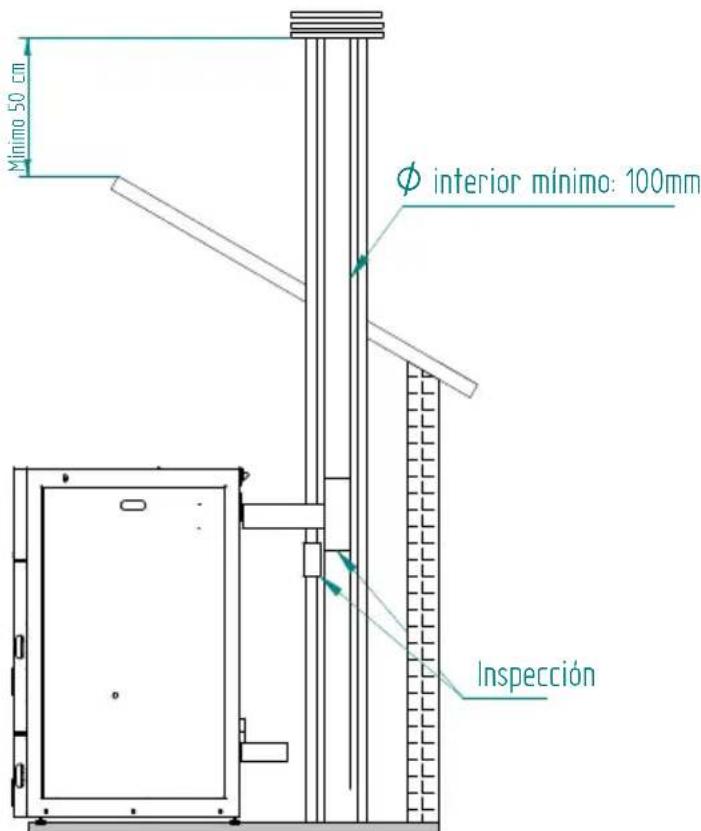
Figure 7 – Side view of the boiler installation with a shaft, highlighting the inspection point.
It is recommended that the boiler not be used during adverse weather conditions that may seriously disrupt the unit's fume extraction capacity (this is especially the case with very strong winds).
If you do not use the unit for a long time, check it to make sure that the flue pipes are clear before lighting the fire.
4.5. Hydraulic Installation
* Chapter 12 (installation diagrams) includes diagrams illustrating the range of possible connections that may be used in the installation of a central heating system, with or without the feature of heating water for domestic use;
* The pellet-run boiler comes equipped with a circulating pump, an expansion tank
(with a volume of 10 litres, in the case of the 18kW model, and of 16 litres, in the case of the 24kW and 30kW models) with a pre-charge pressure of 1.0 bar, as well as a 3 bar safety valve;
* Operating pressure is between 1 and 1.5 bars;
* To empty the unit, attach a "T-tube" with a tap to the outlet (connected to the household sewage); the safety valve (3 bar) outlet must also be connected to the household sewage;
* The heat transporting fluid must consist of water mixed with an anti-corrosion, non-toxic product added in the quantity recommended by the manufacturer. If there exists any risk of freezing in the space where the boiler is installed, or within its fluid pipes, the installation engineer must add the manufacturer's recommended quantity of anti-freeze agent to the circulating fluid, in order to avoid freezing at the absolute minimum expected temperature.
4.6. Operating mode for radiator/Buffer tank
IMPORTANT! The boiler is programmed to work directly for radiators, in case you want to install the boiler with a buffer or AQS tank, we recommend changing the temperature "OFF" of the circulation pump by placing the same temperature as the deposit or 1 °C higher than this temperature, should disable the "hYDRO Menu" modes "Modulating Pump" and "hydro independent" and switch the mode display "Auto" to "Manual" mode and select the power 5 (Fire 5).
You must change the smoke temperatures ("Toff" and "Ton") in the "Activation" menu. For these changes is necessary to access the "Installer Menu" on the display, please request a password manufactures.
5. Fuel
The boiler must be exclusively fuelled by pellets. No other fuel may be used. Use only pellets certified by standard EN 14961-2 grade A1, 6mm in diameter and a length between 10-30mm.
The pellets may have a maximum humidity of 8% their weight. To guarantee a good combustion, the pellets must maintain these characteristics so they should be stored in a dry place.
The use of pellets of varied quality reduces the boiler's efficiency and leads to an inadequate combustion process.
You should always use certified pellets and must not forget to test a sample before buying large bulks.
The physical/chemical properties of the pellets (calibre, friction, density and chemical composition) may vary within specific tolerances and according to each manufacturer. Please note that this may cause alterations to the feeding process and, consequently, the need for different doses (more or less pellets).
The boiler's pellet dosage can be adjusted during the start-up phase and at the power thresholds of ± 25% (see the manual - temporary and power settings)

Warning!
The unit must NOT be used as an incinerator.
6. Use of the pellet-run boiler
Recommendations
Before starting up the unit, please check the following:
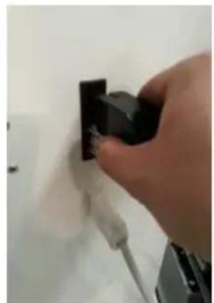
- Guarantee that the boiler is properly connected to the power mains by means of the 230 VAC power cable.

natural_image
Close-up of a metallic electrical plug with a cable inserted, showing no visible text or symbolsFigure 8 – Electric power plug.
- Check to see whether the pellet reservoir is supplied with pellets. Inside the pellet reservoir is a safety grid to prevent users from reaching theworm screw.
• Always check whether the burner is unblocked before igniting the boiler.
The boiler's combustion chamber, as well as its doors, are made of iron plate painted with high temperature resistant paint. Fumes are released during the initial burning sessions due to the curing of this paint.
Avoid touching the unit during its first burn to prevent leaving permanent marks on the paint. The paint goes through a more plastic phase during the curing process. The curing of the paint occurs at approximately 300irc C and for 30 minutes.
Ensure that the hydraulic circuit was correctly assembled and is connected to the water supply;
You should check that there is sufficient ventilation in the room where the unit is installed, otherwise it will not work properly. You should therefore check to see whether there are other heating air-consuming units in the room (e.g. gas units, oil boilers, etc.), which should not be used simultaneously with the unit.
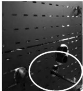
The pellet-run boiler is equipped with a sensor probe for measuring room temperature. This probe is attached to the grid located on the back panel of the unit (Figure 9). For a good reading of the room temperature, avoid the contact between the end of the probe and the unit chassis. You may also attach the probe to the wall beside the unit.

natural_image
Close-up of a metal spiral cable attached to a perforated black wall with black rectangular cutouts (no text or symbols visible)Figure 9 – Room temperature sensor probe
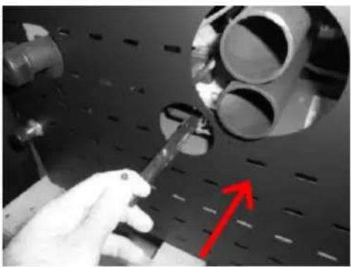
At the first start of the boiler or After some time without use, the linear cleaning motor might create some mechanical resistance to movement, hindering its proper functioning. Before putting the boiler into operation you must press the black button, in the upper zone of the motor (fig. 10-a), and holding the button (fig. 10-b), move the arm repeatedly back and forth (as shown in the figures 10-c and d) until it returns to work normally.

natural_image
Close-up of electronic components with wires and a black arrow pointing to a component (no visible text or symbols)a)

natural_image
Close-up of hands connecting wires to a mechanical component with an arrow pointing to a detail (no visible text or symbols)b)

natural_image
Close-up of a hand holding cylindrical components with an arrow pointing to a small circular object on a perforated surface (no text or symbols visible)c)

natural_image
Close-up of a hand using a tool to inspect or install cylindrical components on a perforated metal plate (no visible text or symbols)d)
Figure 10 – The cleaning motor
Nota: The cleaning motor arm of the boiler backs to clean the burner as shown in Figure 11.
natural_image
Close-up of a metal grate with perforated panels and two circular insets showing mechanical components (no text or symbols visible)Figure 11 – The cleaning motor
7. Remote Control
7.1. Remote control and display
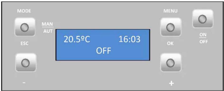
Figure 12 – Command panel and display

a) Key to toggle between manual and automatic mode and exit menus (esc).

b) Key to access menus and confirmation key (ok).

c) Key to start/stop the unit operation and reset error messages

d) Key to scroll the menus to the left, to increase and reduce the fan flow and increase or reduce the set-point temperature.
e) Key to scroll menus to the right and increasing and to reduce the unit's power.
Figure 13 – Command panel buttons
7.2. Display information summary
Menu
Menu indicating the room temperature in °C, the time and that the boiler is "OFF".

"Auto" mode: in this mode, the unit shall be turned on at maximum power until reaching a temperature of 1ircC above the temperature selected (set point temperature). Upon reaching the set temperature, the unit changes to minimum operating power.
The set-point temperature can be set between 5 and 35ircC by pressing the "-" key. The "+" key allows the user to set the ventilation speed between 1-5 and automatic mode.
Water temperature
Press the Menu key twice to set the water temperature;
"Temp. Agua" (Water Temp.) appears on the display. Press Set to see the "T. Aquecimento" (Heating T.) menu.
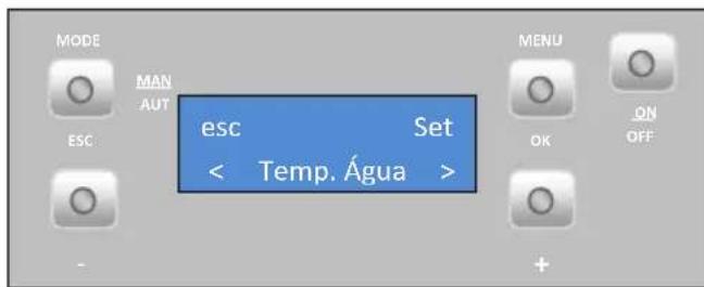
- Heating temperature
To set the desired heating temperature press "set"; the display starts to flash. Press the "+" or "-" key to select the desired value and then "ok" to confirm. Press the "+" key to go to the "Temperatura de sanitários" (Bathroom Temperature) menu.

- Bathroom temperature (this mode is disabled)
Date/Time
To set the date and time: press the Menu key twice and "Dia e Hora" (Date and Time) appears on the display. Press "set" to see the "Hora" (Time) menu.
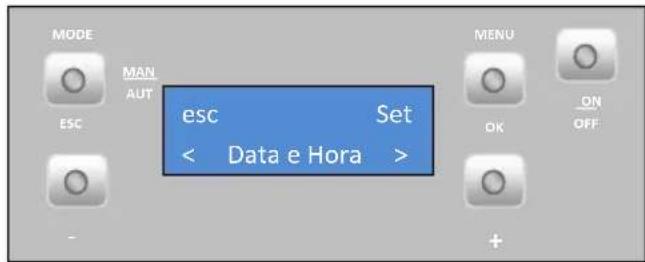
- Time
To set the time press "set". The display starts to flash. Press the "+" or "-" key to select the desired time and then "ok" to confirm. Press the "+" key to go to the "Minutos" (Minutes) menu.

- Minutes
To set the minutes press "set". The display starts to flash. Press the "+" or "-" key to select the desired minutes and then "ok" to confirm. Press the "+" key to go to the "Dia" (Day) menu.

- Day
To set the weekday press "set". The display starts to flash. Press the "+" or "-" key to select the desired day and then "ok" to confirm. Press the "+" key to go to the "Dia Num." (Day Number) menu.

• Day of the month
To set the day of the month press "set". The display starts to flash. Press the "+" or "-" key to select the desired day and then "ok" to confirm. Press the "+" key to go to the "Mês" (Month) menu.

- Month
To set the Month press "set". The display starts to flash. Press the "+" or "-" key to select the desired Month and then "ok" to confirm. Press the "+" key to go to the "Ano" (Year) menu.

- Year
To set the year press "set". The display starts to flash. Press the "+" or "-" key to select the desired year and then "ok" to confirm. Press "esc" to return to the "Dia e Hora" (Date and Time) menu then "+" scroll to the next menu. The Crono (Timer) menu appears.

Timer
The boiler is equipped with a timer that allows it to be programmed to turn on or off at a specified time of day.
- Activation
To activate the timer press "set". The "Habilitação" (Activation) menu appears. The timer may only be activated after setting the configurations, as shown in the following paragraph.

To activate the timer mode press "set". The display starts to flash. Press the "+" or "-" key to select the "On" or "Off" and then "ok" to confirm. Press the "+" key to go to the "Reiniciado" (Reset) menu.

This menu allows you to delete any programme settings. To do this, press "set". The "Confirmar?" (Confirm?) prompt appears. Press "set" again to confirm that you want to delete the settings or "esc" to exit.

The unit's programmer lets you choose from 6 different programmes for each day of the week.
To setup programmes "P1" to "P6", select the desired programme using the "-"e "+" keys, and press "set" to select. "P1 Habilitação" (P1 Activation) menu appears.
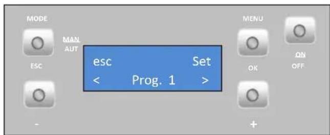
Press "set" again and when the display starts to flash, press "+" or "-" to select "On" or "Off". Press "ok" to confirm the selection. Press the "+" key to go to the "P1 A. Inicio" (P1 A. Start) menu.
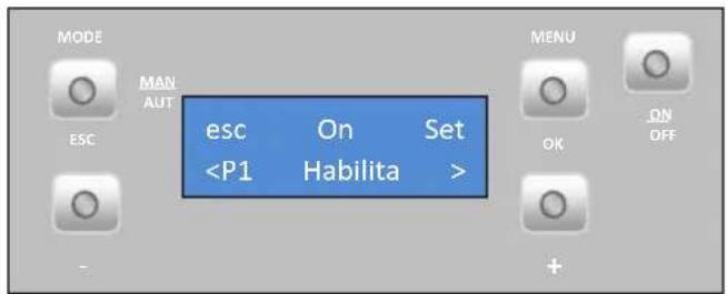
To set the starting time in Programme 1, press "set". The display starts to flash. Press the "+" or "-" key to select the desired time and then "ok" to confirm. Press the "+" key to go to the "P1 A. Stop" menu.
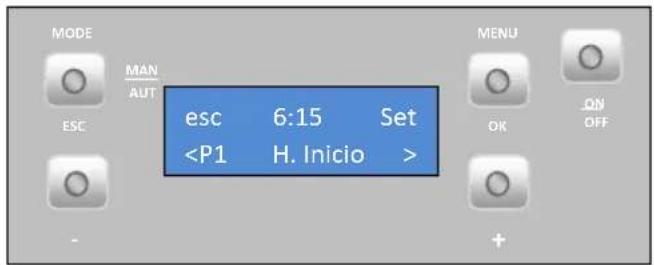
To set the stopping time in P1, press "set". The display starts to flash. Press the "+" or "-" key to select the desired time and then "ok" to confirm. Press the "+" key to go to the "P1 Temp. Ar" (P1 Air Temp.) menu.

To set the set point room temperature in programme 1, press "set". The display starts to flash. Press the "+" or "-" key to select the desired temperature and then "ok" to confirm. Press the "+" key to go to the "P1 Temp. Ar" (P1 Water Temp.) menu.

To set the water set point temperature (only for the backboiler model) of P1, press "set". The display starts to flash. Press the "+" or "-" key to select the desired temperature and then "ok" to confirm.
Press the "+" key to go to the "P1 Fire" menu.

To set the set point room temperature in programme 1, press "set". The display starts to flash. Press the "+" or "-" key to select the desired temperature and then "ok" to confirm. Press the "+" key to go to the "P1 Dia" (P1 Day) menu.

To select the days of the week that you want the P1 programme to run, press "set" and then select the day of the week using the "-" and "+" keys. Press "set". The display starts to flash. Select "On" or "Off" using the "-" and "+" keys. Press "ok" to confirm the selection. Press the "esc" key to go to the "P1 Dia" (P1 Day) menu. Press "esc" twice and then "+" to access the "Configurações" (Configuration) menu.

Repeat the above steps for programmes P2 to P6.
Note: After setting up the programmes, please remember to activate them on the "Habilitações" (Activation) menu.
Sleep
The "Sleep" menu allows you to set the time you want the unit to turn off.

Press "set". The display starts to flash. Select the desired time using the "-" and "+" keys. After choosing the time, press "ok" to confirm. Press "esc" to return to the menu and "+" to go to the configuration menu.

Configuration menu
To modify the boiler's settings, press "Set".
The "Língua" (Language) menu appears allowing you to select the language.

To select the language, press "set". Using the "+" or "-" keys, select the desired language (Pt - Portuguese; NI - Dutch; Gr - Greek; It - Italian; En - English; Fr - French; Es - Spanish; De - German). Press "ok" to confirm.
Press the "+" key to go to the "eco" menu.

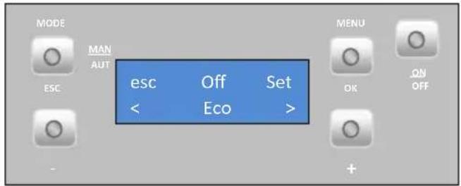
- Eco mode
When you activate the mode "ECO" with the Thermostat function, the boiler operates at full power until the thermostat open contact (NO) and passing operating at minimum power during a predetermined time interval (Shutdown delay time: factory setting : 20 minutes). After this time, the boiler is turned off. From the beginning of boiler shutdown phase we have to count another predetermined time interval (delay time Starup: default value: 20 minutes), so that when the thermostat closes the contact (NC), Pass to activation phase.
Startup delay time (waiting time On) is the waiting time after the thermostat contact close (NC), to enable the boiler.
Shutdown delay time (waiting time Off) is the waiting time after the thermostat contact open (NO) to switch off the boiler.
To activate the eco mode, press "set". The display starts to flash. Select "On" or "Off" using the "-" and "+" keys. Press "set" to confirm the selection.
Press "esc" to return to the previous menu and "+" to go to the "Iluminação" (Lighting) menu.
- Lighting
To select lit screen, press "set". The display starts to flash. Press the "+" or "-" key to select the time at which you want the screen to light up, or choose "On" to keep the light on at all times. Press "ok" to confirm. Press the "+" key to go to the "Tons" (Tones) menu.

To activate the key tone, press "set". The display starts to flash. Press the "+" or "-" key to select "On" or "Off". Press "ok" to confirm. Press the "+" key to go to the "°C/°F" menu.

- Temperature unit (ircC/ircF)
To select °C / °F, press "set". The display starts to flash. Press the "+" or "-" key to select "°C", "°F" or "Auto", and then "ok" to confirm. Press the "+" key to go to the "Receita Pellet" (Pellet Qty) menu.

- Pellet quantity
- Temporary settings
This feature allows you to increase or decrease by 25% the amount of pellets at start-up. Press "set". The display starts to flash. Press "+" or "-" to increase or decrease (between -5 to +5), accordingly. Each unit must be multiplied by 5 to obtain the correct percentage. Press "ok" to confirm. Press the "+" key to go to the "Actuações de Potência" (Power settings) menu.

This feature allows you to increase or decrease by 25% the amount of pellets at each power level. Press "set". The display starts to flash. Press "+" or "-" to increase or reduce (from -5 to +5), accordingly. Each unit must be multiplied by 5 to obtain the correct percentage. Press "ok" to confirm. Press "esc" to return to the "Receita de pellets" (Pellet Qty) menu and "+" to go to the "Termostato" (Thermostat) menu.

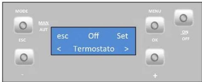
- Thermostat
This feature allows you to enable or disable the room temperature thermostat. Press "set"; the display starts to flash. Press the "+" or "-" key to select the "On" or "Off" and then "ok" to confirm. Press the "+" key to go to the "Carga Pellet" (Pellet loading) menu.
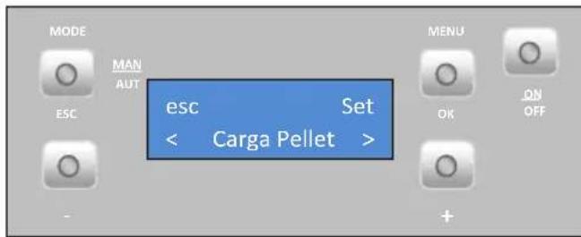
- Pellet loading
This feature allows you to enable the worm drive to fill the channel when it is empty to keep the unit running. Press "set"; the "ok" option appears. Press "ok" to activate the drive (the "habilitada" (Activated) message appears) and "esc" to stop it. Press the "+" key to go to the "Limpeza" (Cleaning) menu.
- Cleaning
This feature allows you to clean the burning basket manually. Press "set"; the "ok" message appears. Press "ok" to start the cleaning; the "Habilitada" (Activated) message appears. When you wish to stop, press "ok". Press the "+" key to go to the "Técnico" (Technical) menu.

The technical menu is not available to the end user since it includes exclusively factory settings that must never be changed.
10.1. User Info
This menu allows the user to visualise information about the boiler. Press "set"; the "Código de Ficha" (File Code) menu appears. Display software/firmware code Press the "+" key to go to the "Horas Funcionamento" (Operating Hours) menu.


This menu indicates the number of hours the boiler has been operating.
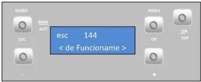
Fume extractor operating speed (rotation per minute).
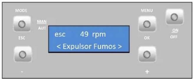
Airflow measured by the air probe.

Fume temperature.

Worm drive rotation time ("On").

Ventilation power level.

Hydraulic circuit pressure

To start up the pellet-run boiler, press the start/stop button for 3 seconds. The display should indicate "Acendimento" (Lighting) until this completion of this phase.
The pellets will be pushed through the supply channel into the burning basket (combustion chamber), where they will be ignited using a heater coil. This process may take between 10 and 15 minutes, depending on whether the pellet transport worm screw has been previously loaded with fuel or is empty. Upon completion of the ignition phase, the word "On" should appear on the display.
8.1. Stoppage
The unit stop sequence is activated by pressing the “On/Off” key for 3 s. The display shows the “desactivação” (deactivation) message until this phase is completed. The extractor will remain active until the fume temperature reaches 59 °C.
8.2. Turn off the unit
The unit should only be disconnected after stoppage.
Make sure that the display indicates “Off”. If necessary, disconnect the power cable from the mains.
8.3. Instructions for removing the side covers
8.3.1. Remove side covers
Lift the cover, pulling up and forward, thus removing it from the upper and frontal slots. Do the opposite to assemble the unit.

natural_image
Hand placing a button on a dark metal cabinet (no text or symbols visible)Figure 14 – Removal of side covers
8.3.2. Pellet reservoir lid
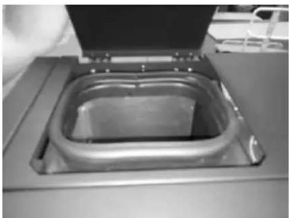
The pellet reservoir is opened by sliding the bolt sideways (Figure 15-a) and then lifting up the lid (Figure 15-b).

natural_image
Close-up of a hand pressing down on a dark surface with a small object partially visible (no text or symbols)c)
natural_image
Interior view of a stainless steel appliance with a rectangular lid and open lid (no visible text or symbols)b)
Figure 15 – Opening the lid
8.4. Filling the pellet reservoir
1 - Open the pellet reservoir lid located at the top of the unit, as shown in Figure15-b.
2 - Pour the pellets into the reservoir, as shown in Figure 16.

natural_image
Close-up of a transparent plastic tray with a rectangular opening, mounted on a metal base (no visible text or symbols)Figure 16 – Refilling the pellet reservoir
3 – Turn on the unit and close the lid of the reservoir, pressing down as shown in Figure 15.
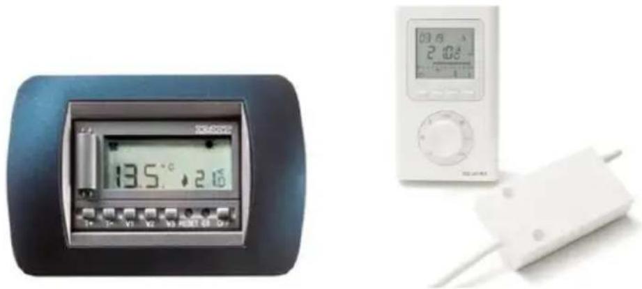
8.5. Installation and operation using remote command (chrono-thermostat) – not included with the boilers
The pellet-run boilers are mass produced with a command display. Alternatively, the units can be operated using a generic remote command unit (chrono-thermostat).
Note: the remote command unit normally comes accompanied by a manual. An interface must be installed in order to use the remote command (17–c).
natural_image
Two electronic devices: a digital timer displaying 13.5°C and a white handheld device with a 2:08 reading (no visible text or symbols on main components)a) b)

c)
Figure 17 – Remote command unit (chrono-thermostat) and connection interface – both not included.
This board has two entries "remote" and "therm" to conect the chrono-thermostat into the "remote" the user of the start (closed contact NC) and stop (open contact NO) the boiler.
If connecting into the "thermostat" This will only change the power of the machine between minimum output (open contact NO) and maximum power (closed contact NC).
Note: the external command, as a rule, comes with a manual. In the case of wireless remote control is necessary to connect the two wires as shown in the following figure:
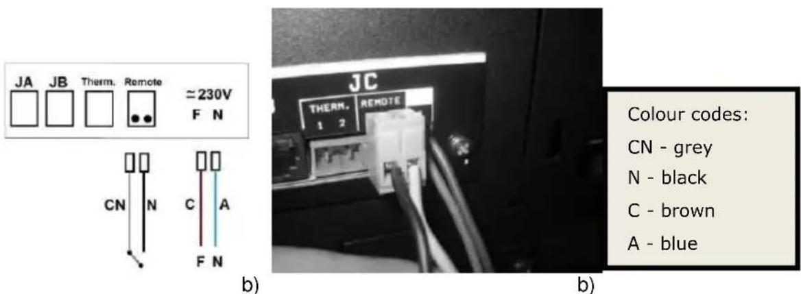
Figure 18 – Wireless remote command connection
For the wired remote control, the black and grey wires must be connected to the receiver as shown in the following figure.
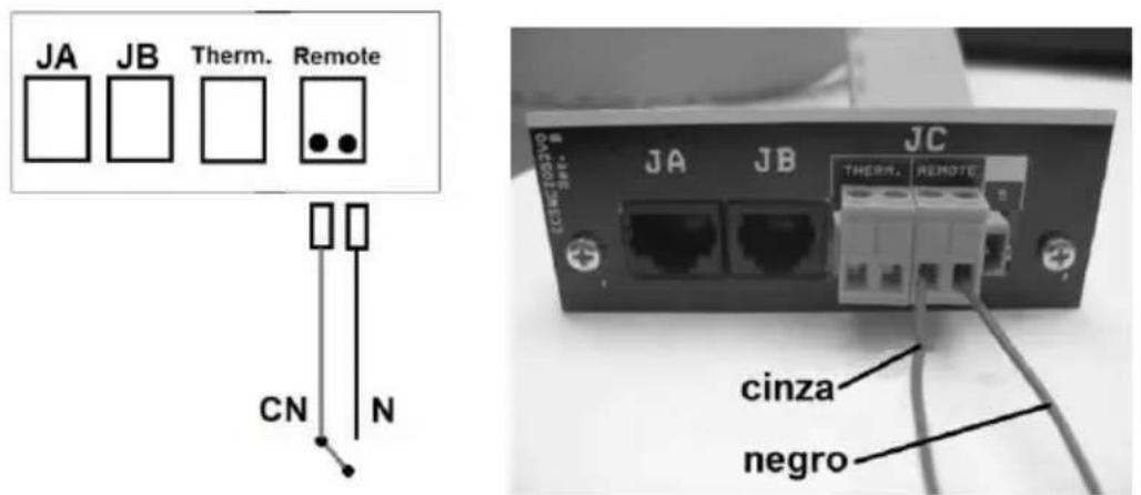
Figure 19 – Wired remote command connection
Instructions for remote control assembly
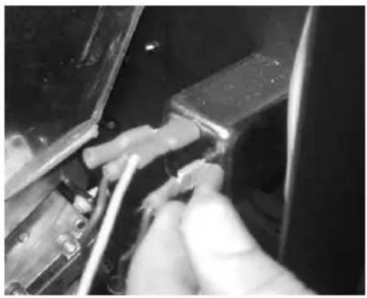
1 – Turn off the equipment at the main power switch and remove the right-hand side of the pellet-run boiler.
2 - Remove the unit's terminals phase (F) and neutral (N).
natural_image
Close-up of hands using a tool to adjust or install electronic components (no visible text or symbols)a)
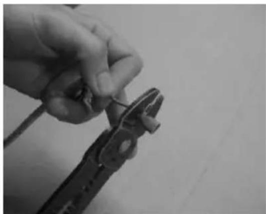
3 - Rivet the terminals of the 220V wire supplying power the transmitter.

natural_image
Two black-and-white photos showing hands using pliers to adjust or install a wire; no text or symbols visible.b)
c)
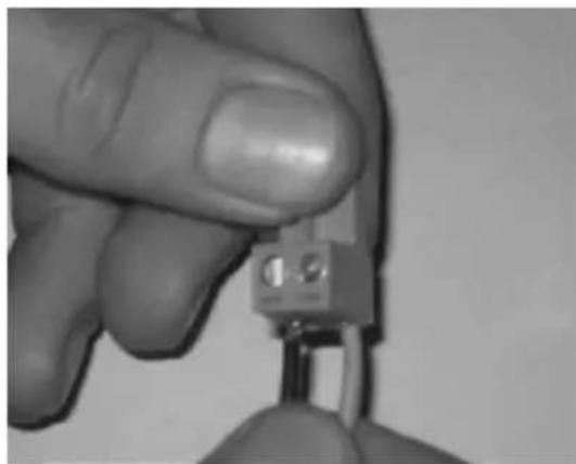
4 – Attach the wires to the connector of the ON/OFF contact (Figure 20-d); Direct these same wires through the cable gland into the interior of the boiler (Figure 20 – e);
natural_image
Close-up of a hand holding a small electronic component (no visible text or symbols)d)

natural_image
Close-up of a metallic door with a rectangular panel and a white arrow pointing to a detail (no text or symbols visible)e)
5 - Connect the plug of the remote command (On/Off contact) to the "Remote" socket (Figure 20);.

natural_image
Close-up of a hand holding a computer interface with three connected ports (no visible text or symbols)f) g)

Figure 20 - Installation of the chrono-thermostat
9. Installation of the external silo
Solzaima's automatic wood pellet boiler has an internal tank with a capacity of 45kg of wood pellets. Solzaima's optional storage unit allows you to increase by about 200kg the amount of wood pellets available, significantly increasing the autonomy of the boiler.
The optional storage unit set includes:
- Storage unit;
- Casters for moving the storage unit;
- Worm drive channel to transport the pellets into the boiler's internal tank;
- Electric power engineer to rotate the worm drive screw;
- Circuit board with wiring included;
- pellet level sensor of the storage unit
Together with the storage unit a connection kit to the boiler is provided and it includes:
- Instruction manual;
- Storage unit instruction manual;
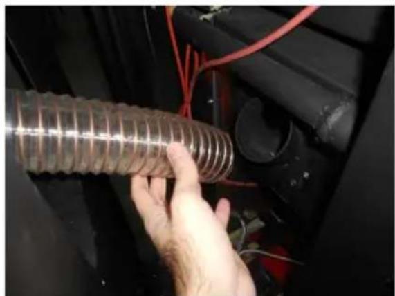
- Flexible hose with metal bracket to connect the storage unit to the boiler;
- Cable to connect the storage unit level sensor and Pellet level sensors for the
boiler's internal tank to the circuit board;
- Cable for electrical connection of the deposit;
- Ramp to put inside the boiler's tank;
- Parts for the rear and lateral fixation of the storage unit to the boiler;
- Screws for attaching the level sensors to the tank of the boiler.
Description of operation
When the level sensors of the boiler's internal tank ceases to detect pellets (the sensor lights go off) the electric power engine of the storage unit is triggered, by rotating the worm drive screw of the storage unit. Thus the pellets are transported from the storage unit to the boiler's internal tank. The electric power engine will run continuously until the sensors in the boiler's tank detect pellets again (sensor lights turn on). When this happens, the electric power engine stops.
Thus, the storage unit system will be triggered each time the pellets level in the boiler's tank is low, preventing the boiler's flame is extinguished due to the lack of pellets.
In the storage unit, there is also a sensor that detects the level of pellets. When the pellets level is low, the sensor will cease to detect the pellets (the sensor light
goes off) and will appear on the display a message of troubleshooting. After 40 seconds will appear on the boiler's display na alarm signal (code A15) and the boiler shuts down. The electric power engine keeps running, fueling the boiler's internal tank until the sensors detect pellets.
To restart the boiler, you will have to refill the storage unit with pellets (at least until the level sensor detects pellets) and reset the error (see automatic boiler instruction manual).
The wood pellet storage unit can be installed on either the left or right side of the boiler. By default, it is configured to be installed on the right side of the boiler.

For greater ease you should proceed to the assembly and adjustment of the storage unit before installing the boiler.
Adjusting the height of the boiler
With the boiler placed in its final position, and before starting the installation of the storage unit, you should level the boiler and put it at the same height of the storage unit. To do so, you should place the storage unit beside the boiler (left or right) and adjust the leveling feet of this until it is aligned with the storage unit by the upper zone, as shown in the following pictures.

Figure 21 – Adjusting the height of the boiler
Adjusting the sensor's response time and sensitivity
You can adjust the pellet level sensor's sensitivity. The higher the sensitivity, the better the sensors will detect the pellets in their proximity to send an electric signal to the control circuit board.

natural_image
Two identical yellow rectangular blocks with black square heads and curved lines, no text or symbols present.a) b)
Figure 22 – Difference between a level sensor with low sensitivity (a) and high sensitivity one (b)
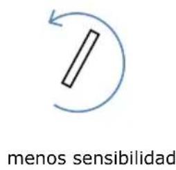
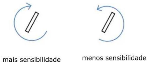
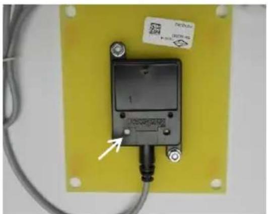
To set the sensor to the required sensitivity rotate the knob (Figura 23-a) clockwise to increase the sensitivity or counter clockwise to decrease it (Figura 23-b).
natural_image
Close-up of a black electronic device mounted on a yellow PCB with wires and a label (no readable text or symbols beyond the label)a) b)
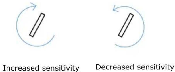
Figure 23 – Adjusting the level sensor sensitivity
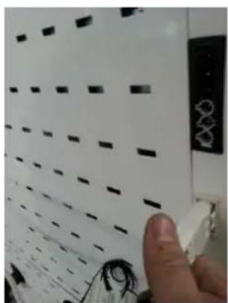
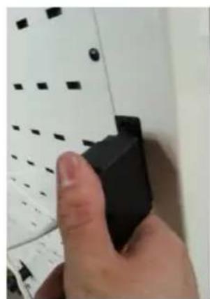
1 – To adjust the sensitivity must connect the tank to the boiler using the cable Kit.

natural_image
Hand inserting a small white object into a wall corner with a black rectangular component (no visible text or symbols)a)

natural_image
Close-up of a hand using a screwdriver to adjust or install a black electrical socket (no visible text or symbols)b)

natural_image
Close-up of a hand pointing at a white panel with black dashed lines and a small electronic device (no visible text or symbols)d)

natural_image
Close-up of a hand holding a black 3D object against a white background with grid patterns (no text or symbols visible)e)
Figure 24 – Connecting the sensors to the circuit board
2 – Next, you should remove the storage unit's level sensor. By default, it comes installed on the left side of the storage unit (the storage unit is set up by default to be installed on the right side of the boiler). To do this, loosen the screws of the part that supports the sensor and remove the set.

natural_image
3D technical diagram of a mechanical assembly inside a rectangular housing (no text or symbols visible)Figure 25 – Removing the storage unit's level sensor
3 – With the sensors already connected to the circuit board, you must connect the boiler to the mains.
4 – You should put some pellets in a container, and next to the boiler, perform the sensitivity adjustment, as described in the following steps:
- put the sensor over the pellets;

natural_image
Exterior view of a rectangular electronic device with a black component and wiring, placed on a textured surface (no visible text or symbols)Figure 26 – Placement of the sensor over the pellets
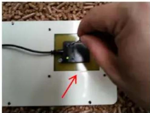
- Rotate the adjustment knob counter clockwise so that the lights go out (if they are not already out) –

natural_image
Hand holding a small electronic component with wires, placed on a white panel with a red arrow pointing to it (no text or symbols visible)a) b)
natural_image
Hand holding a small electronic component with wires and a red arrow pointing to it, placed on a white panel with scattered wooden blocks in the background (no text or symbols visible)
natural_image
Close-up of a small electronic device mounted on a white rectangular base with a black cable and red arrow pointing to it, placed on a textured surface (no text or symbols visible)c)
Figure 27 – Adjustment of the sensor sensitivity
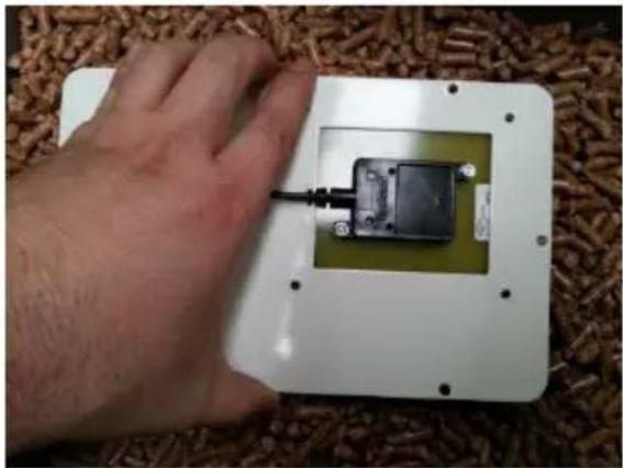
- Then, with the light of the sensor on, you should move the sensor away from the pellets and check that the light go out (Figura 28-a) and re-approach and check that the light come on when approaching the pellets (Figura 28-b)
natural_image
Hand holding a small electronic device mounted on a white rectangular base, placed on a woven mat (no visible text or symbols)a) b)

natural_image
Hand holding a small electronic device mounted on a white rectangular base, placed on a woven mat (no visible text or symbols)Figure 28 – Adjustment of the sensors sensitivity
- If the light do not go out when moving the sensor away from the pellets or do not come on when approaching, re-adjust the sensitivity of the sensor and repeat the test.
- You shall perform the sensitivity adjustment for both the boiler's tank level sensors and for the storage unit's level sensor.
You can also adjust the sensor's response time, to set the time the sensor waits before sending the signal to the circuit board upon detecting the pellets. This setting can be made directly on the storage unit electronic circuit board, on the upper right corner, using the same procedure used for adjusting the sensitivity – rotate clockwise to increase the response time and counter clockwise to decrease the response time.

The response time should be set to the minimum value
Installing the storage unit on the right side of the boiler
The level sensor of the storage unit must always be installed on the side closest to the boiler.
1 – If you want to install the storage unit on the right side of the boiler you must install the level sensor on the left side of the storage unit, in the same place where he comes assembled by default. Before, you should disconnect the plug of the cable connected to the circuit board, to facilitate the assembly. To fasten it, you should use the screws previously removed, and put it in the position shown in Figura 29-b.

natural_image
3D technical illustration of a mechanical assembly or enclosure with internal components and mounting brackets (no text or symbols)a) b)

natural_image
Pure technical diagram showing a mechanical assembly with no text, numbers, or symbolsFigure 29 – Installing the sensor level in the storage unit
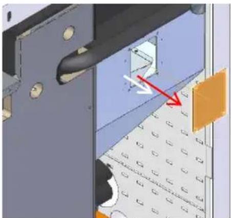
2 – Then, you should install the ramp to drop the pellets in the boiler's internal tank. For this, you should start by removing the right side cover of the boiler's tank – removing the 4 screw securing it (Figura 30).
natural_image
3D mechanical assembly diagram showing a component with highlighted section and directional arrows (no text or symbols)Figure 30 – Removing the lateral cover of the boiler's tank
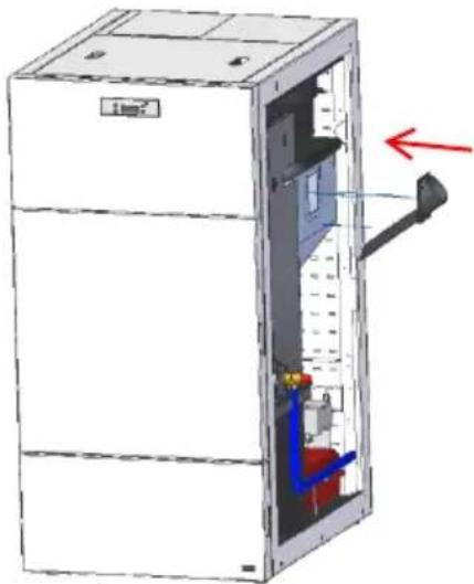
3 – To assemble the ramp to drop the pellets you should insert it in the tank, as shown in the following pictures, and fasten it with the screws previously removed.
natural_image
3D diagram of an open industrial refrigerator with internal components and a red arrow indicating direction (no text or symbols)a)

natural_image
Hand installing or adjusting a black panel with red cables and orange wires, no visible text or symbolsb)

natural_image
Close-up of a hand using a black tool to adjust or install a mechanical component with red wires (no visible text or symbols)c)

natural_image
Close-up of a black industrial pipe fitting with a circular component and coiled tubing (no visible text or symbols)d)
Figure 31 – Assembly of the ramp to drop the pellets in the boiler's tank
4 – Before proceeding with the assembly of the storage unit, you should check if the worm drive channel is properly docked in its base. To do this, open the lid of the storage unit and check if the docking is in accordance with Figura 32-a. Also, check if the pellet's output tube is in line with the opening of the storage unit (Figura 32-b).

natural_image
Technical diagram of a pipe joint with a black cylindrical component and red dashed lines indicating a dimension (no text or symbols present)a)

natural_image
3D rendered mechanical part with a red dashed line and circular feature, no visible text or symbolsb)
Figure 32 – Worm drive channel for storage unit installation on the right side
5 – Place the flexible hose on the storage unit's pellet output tube and attach it using the metal bracket provided. The flexible hose must make a downward curve (Figura 33-c).

natural_image
Hand holding a transparent plastic hose attached to a black door (no text or symbols visible)a) b)
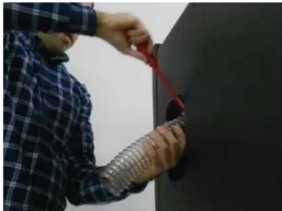
natural_image
Person in plaid shirt installing or adjusting a red cable near a black wall (no text visible)
natural_image
Close-up of a transparent plastic hose with coiled spring, mounted on a black surface with dashed white lines indicating alignment (no text or symbols)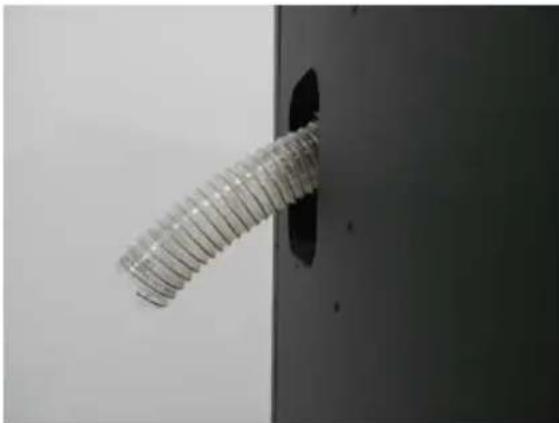
natural_image
Close-up of a metallic threaded screw fastener inserted into a black hole on a dark panel (no text or symbols visible)c) d)
Figure 33 – Installing the flexible hose
6 – Then, you should approach the storage unit to the boiler and insert the flexible hose into the ramp to drop the pellets (Figura 34 – b e c). The storage unit must be at a spacing of 1 cm to the side of the boiler and must be aligned with this by the rear.
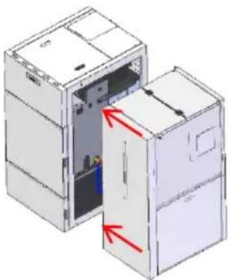
natural_image
3D diagram of two open industrial cabinets with red arrows indicating internal components (no text or symbols)a)

natural_image
Close-up of a hand holding a transparent coiled cable or hose attached to a black industrial machine (no visible text or symbols)b)

natural_image
Close-up of a mechanical component with red arrow indicating direction, no visible text or symbolsc)
Figure 34 – Placing the storage unit next to the boiler (a); connecting the storage unit to the boiler's pellet tank (b e c)
7 – To make the fixing of the storage unit to the boiler you will have to remove the upper lids of the storage unit. Remove the 2 screws at the back (Figura 35-a); open the front lid and remove the 3 screws that secure the lids to the central bar (Figura 35-c).
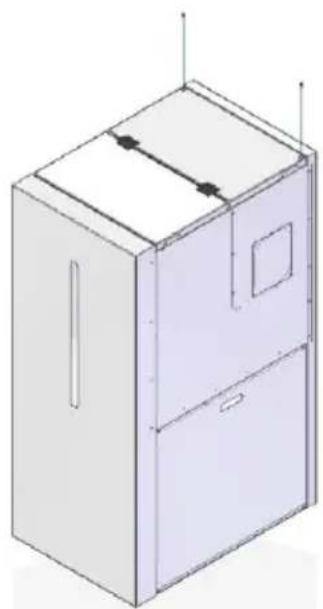
natural_image
Isometric line drawing of a cabinet or enclosure with internal compartments and ventilation slots (no text or symbols)a) b)

natural_image
Isometric line drawing of a cabinet with open lid and side compartments (no text or symbols)
natural_image
3D technical line drawing of a cabinet or enclosure with internal compartments and a red arrow indicating direction (no text or symbols)c) d)
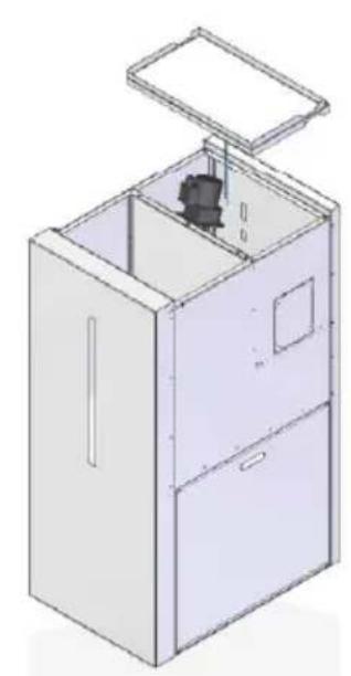
natural_image
Isometric line drawing of a cabinet with an open lid and internal components (no text or symbols)Figure 35 - Removing the upper lids
8 – After removing the lids you should secure the storage unit to the boiler assembling, at the back, the provided part, and secure it with the screws, as shown in the following figures.

natural_image
3D diagram of a room corner with a green component and directional arrows indicating movement or force (no text or symbols)a) b)
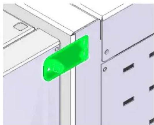
natural_image
3D diagram of a mechanical or electrical component with a green-labeled component, no visible text or symbolsFigure 36 – Attaching and securing the storage unit to the boiler – Rear view
9 – The adjoining sides of the storage unit and the boiler should be secured in place using the screw and the mounting bracket provided.
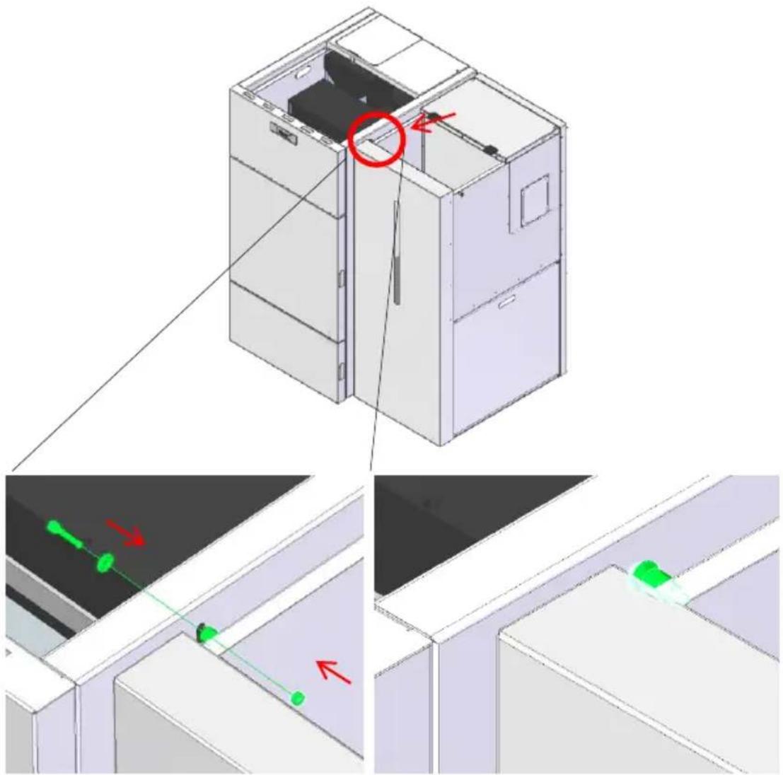
Figura 37 – Attaching and securing the storage unit to the boiler – Side view 10 - Finally, you should place the upper lids and re-attach the screws.

natural_image
3D technical illustration of a cabinet with an open lid and internal components, showing no text or symbols.Figura 38 – Replacing the upper lids
Installing the storage unit on the left side of the boiler
The storage unit is set up by default to te installed on the right side of the boiler. If you wish to install it on the left side, please follow these steps.
1 - First, remove the upper lids by loosening and removing the two retaining screws on the rear (Figura 39-a). Then, open the front lid and remove the 3 scres (Figura 39-c) that hold the lids in place.
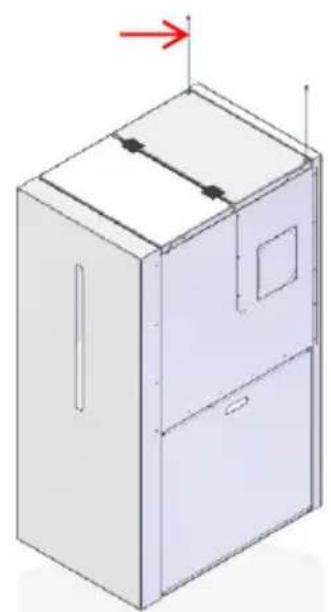
natural_image
Isometric line drawing of a cabinet with an arrow indicating direction (no text or symbols)a) b)

natural_image
3D line drawing of a cabinet with an open lid and a red arrow indicating rotation (no text or symbols)
natural_image
Isometric line drawing of a cabinet or enclosure with a red arrow indicating a component (no text or symbols present)
natural_image
Isometric line drawing of a cabinet with an open lid and internal components (no text or symbols)c) d)
Figure 39 - Removing the upper lids
2 – Next, remove both side lids (Figura 40-a) and the retainer that holds the worm drive screw channel in place, inside the storage unit (Figura 40-b)

natural_image
3D diagram of a cabinet with green panel and red arrows indicating assembly or movement (no text or symbols)a) b)

natural_image
3D line drawing of a cabinet with a green handle and black interior components (no text or symbols)Figure 40 – Removing the side lids and plate
3 - To place the pellets' output on the right side of the storage unit, loosen both screws shown in Figura 41-a (you don't need to remove them completely), and rotate the channel upper assembly (including the drive's assembly) clockwise. Once the procedure is completed, retighten the two screws.

natural_image
3D CAD model of a mechanical assembly with internal components and mounting holes (no text or symbols visible)a) b)

natural_image
3D technical illustration of a mechanical component with no visible text or symbolsFigure 41 - Worm drive set rotation
4 – Afterwards, you must slide the worm drive channel to the right side of the storage unit (Figura 42-a), by lifting it up and rotating it clockwise so that it fits the base aligned diagonally with the holes (Figura 42-b).

natural_image
Technical diagram showing a mechanical assembly inside a container with directional arrows indicating motion (no text or symbols present)a) b)

natural_image
3D mechanical assembly diagram showing a cylindrical component inserted into a housing, with no visible text or symbolsYou should remove the lower side lid of the storage unit to access the worm drive channel retainer to facilitate its placement at the base.

natural_image
3D architectural rendering of a building interior with a green indicator light and label 'A' (no text or symbols on the diagram itself)c)
When the procedure is complete, the pellet output should be perpendicular to the side panel of the storage unit.

natural_image
Technical diagram showing a mechanical assembly inside a container with no visible text or symbolsd)

natural_image
3D rendered mechanical part with a red vertical line and circular outline, no visible text or symbolse)
Figure 42 - Sliding the channel to the right side
5 – The level sensor must be assembled on the right side of the storage unit (on the closest side to the boiler). For this, you must change the position of the sensor in the mounting plate in which it is fixed:
- remove the level sensor of the mounting plate, by removing the 4 screws that secure it;

natural_image
Two technical diagrams showing a device assembly with highlighted components and a red arrow indicating a specific section (no text or symbols present)Figure 43 - Removing the level sensor from the mounting plate
- To assemble the sensor on the opposite side of the mounting plate you should mount it as shown in the following figure:
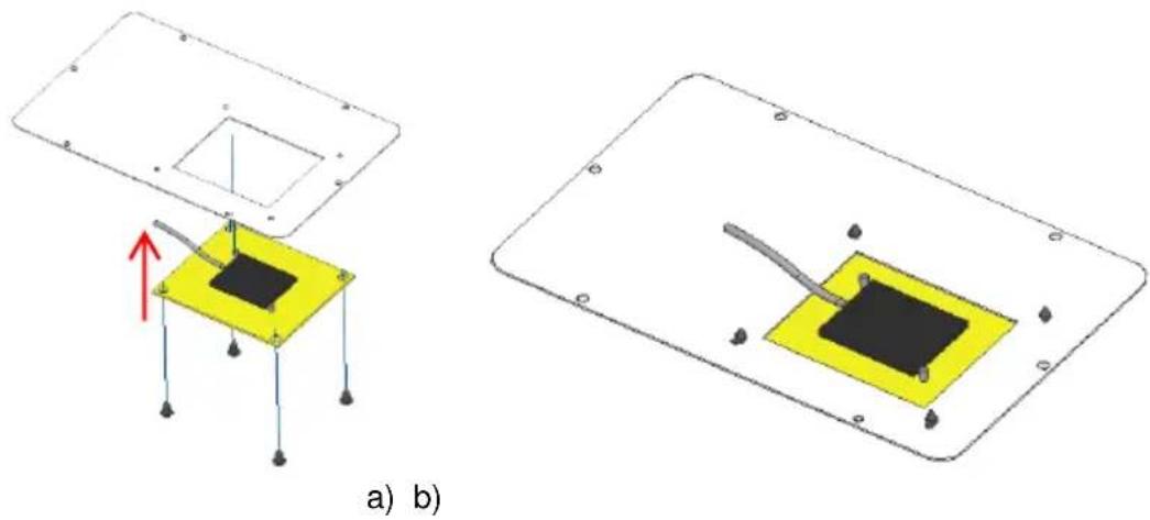
natural_image
Two technical diagrams showing a device with a yellow square base and red arrow indicating force or movement, labeled 'a) b)' (no text or symbols on the diagram itself)Figure 44 - Assembling the level sensor on the mounting part
- Finally, you can mount the two mounting plates at the bottom of the storage unit, putting the plate with the level sensor on the right side and the plate without level sensor on the left side. The level sensor must be assembled as shown in Figura 45-c.
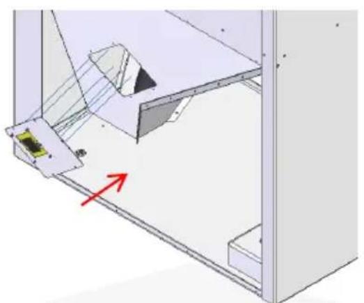
natural_image
3D mechanical assembly diagram showing a bracket with mounting holes and a red directional arrow (no text or symbols)a) b)
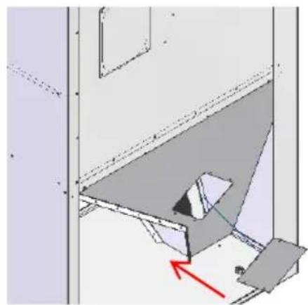
natural_image
3D architectural or mechanical diagram showing a structural component with a red arrow indicating direction (no text or symbols present)
natural_image
Pure technical diagram showing a mechanical assembly with no text, numbers, or symbolsc)
Figure 45 – Installing the pellet level sensor on the storage unit (storage unit on the left side of the boiler)
6 – Replace the worm drive channel retainer inside the storage unit (Figura 46-a). The side lids should now be attached to the left of the storage unit (Figura 46-b).

natural_image
3D diagram of a mechanical device with internal components and a green arrow indicating direction (no text or symbols)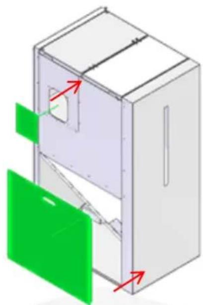
natural_image
3D diagram of a cabinet with green doors and red arrows indicating directional movement (no text or symbols)a) b)
Figure 46 – Installing the worm drive channel retainer and side lids
7 – You should place the flexible hose on the storage unit's output tube and attach it using the metal bracket provided. The flexible hose must make a downwards curve (Figura 47-c).

natural_image
Hand holding a plastic bag attached to a black door handle (no text or symbols visible)a) b)

natural_image
Close-up of hands using a red tool to handle a coiled metal pipe or hose (no text or symbols visible)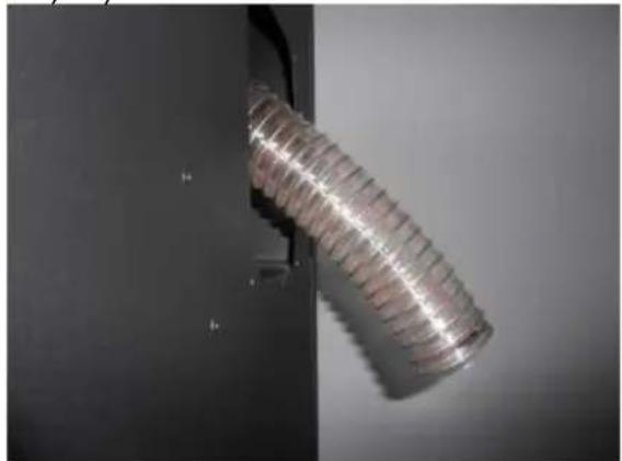
natural_image
Close-up of a coiled metallic cylindrical object with ribbed texture, mounted on a dark surface (no visible text or symbols)c) d)

natural_image
Close-up of a metallic threaded bolt with dashed alignment lines (no text or symbols)Figure 47 – Installing the flexible hose
8 – To adjust the sensitivity must connect the tank to the boiler using the cable Kit.
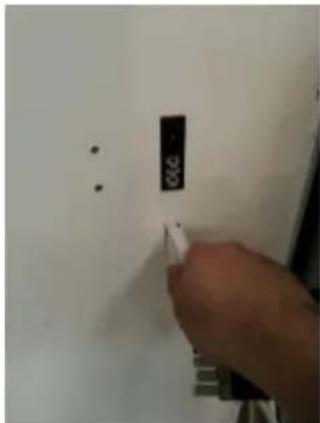
natural_image
Hand inserting a small white object into a wall, with no visible text or symbolsa)

natural_image
Hand inserting a plug into a wall socket (no text or symbols visible)b)
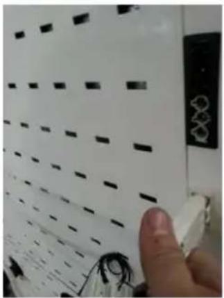
natural_image
Close-up of a hand holding a white electronic device with black circuit lines and a small black connector (no visible text or symbols)d)

natural_image
Close-up of a hand holding a black rectangular object against a white background with grid patterns (no visible text or symbols)e)
Figure 48 – Connecting the level sensor to the boiler
9 – Then, you should approach the storage unit to the boiler and insert the flexible hose into the ramp to drop the pellets (Figura – b e c). The storage unit must be at a spacing of 1 cm to the side of the boiler and must be aligned with this by the rear.

natural_image
3D diagram of an open refrigerator with red arrows indicating internal components (no text or symbols)a) b)
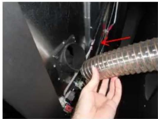
natural_image
Close-up of a hand holding a coiled hose component, with a red arrow pointing to a component (no visible text or symbols)
natural_image
Close-up of a hand adjusting a flexible hose component with red arrows indicating direction (no text or symbols visible)c)
Figura 49 – Placing the storage unit next to the boiler (a); connecting the storage unit to the boiler's pellet tank (b e c)
10 - Then, you should secure the storage unit to the boiler assembling, at the back, the provided part, and secure it with the screws, as shown in the following figures.

Figure 50 – Securing the storage unit to the boiler in the back
11 – The adjoining sides of the storage unit and the boiler should be secured in place using the screw and the mounting bracket provided.

natural_image
3D diagram of a refrigerator interior with a highlighted door and red circle indicating a location (no text or symbols present)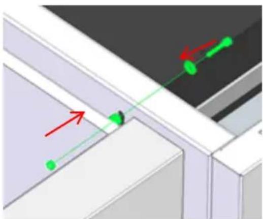
natural_image
3D diagram of a window with green and red directional arrows indicating movement or force (no text or symbols)
natural_image
3D architectural corner detail showing a green object on a white wall (no text or symbols)Figure 51 – Attaching and securing the storage unit to the boiler, on the side
12 – Finally, you should place the upper lids and re-attach the screws.
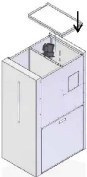
natural_image
3D technical illustration of a cabinet with an open lid and internal components, showing no text or symbols.Figure 52 – Placing the upper lids
Enabling the pellet level sensor
At the end of the storage unit's installation it is necessary to activate the pellet level sensor in the boiler's display. For this, you should enter the technical menu. (Password only provided to authorized technical personnel)

Within this menu, you should enter the General Settings, and in the Pellet Level Sensor menu you should press Set, and then the keys "+" and "-" until it shows On on the display.

When the storage unit runs out of pellets, the level sensor sends a signal and an alarm appears in the boiler's display (A15 code). You should refill the storage unit with pellets, reset the alarm and restart the boiler.
Boiler startup
With the storage unit properly fixed to the boiler (right or left side) you should carry out the hydraulic connections and the connection of the boiler to the fumes outlet. After making the connections, you should introduce some pellets inside the storage unit and start the operation of the boiler. You must observe the pellets falling from the storage unit to the boiler's internal tank and check if the level sensors work properly.

If the sensors do not work properly, you should remove them and re--adjust the sensitivity.
You must observe the boiler working for a time period corresponding to 3 or 4 charges of pellets and check if the pellet level does not rise above the level of the sensors.
10. Maintenance

weekly maintenance
Solzaima's pellet-run boiler includes automatic cleaning systems: one, is found in the upper part of the boiler and is meant for cleaning the fume pipes (Figure 53-a); the other, is located near the base of the burner and is meant for cleaning ashes and any other remaining residue (Figure 21-b).

natural_image
Top-down view of a dark rectangular electronic component with visible wiring and mounting holes (no text or symbols)a)

natural_image
Close-up of hands operating a mechanical device with wires and components (no visible text or symbols)b)
Figure 53 – Automatic cleaning systems
Care should be taken to clean the ash drawer located in the lower part of the boiler (see label warnings and maintenance tasks in Chapter 26). To access the drawer, open the front door (Figure 54) and then the lower door of the boiler (Figure 55).
Figure 54 – Front door of the boiler
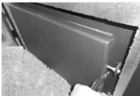
natural_image
Close-up of a dark rectangular panel or panel with a hand partially visible, no text or symbols present.
natural_image
Close-up of a hand adjusting a metal bracket with a tool (no visible text or symbols)Figure 55 – Lower door and ash drawer
Note: Before cleaning the boiler, ensure that the power is turned off and that the unit is cool enough to handle, in order to prevent possible injury.
Cleaning the burner and plate
A cleaning the burner and the plate, as shown in the figures, 56-b, 56-c and 56-d to prevent obstruction of the holes in the burner or some kind of residue ashes must not be made to be gripped plate cleaning.

natural_image
Close-up of a metallic industrial component with a circular opening and a vertical pipe inserted (no visible text or symbols)a)

natural_image
Close-up of a hand pressing down a pipe into a container (no visible text or symbols)b)
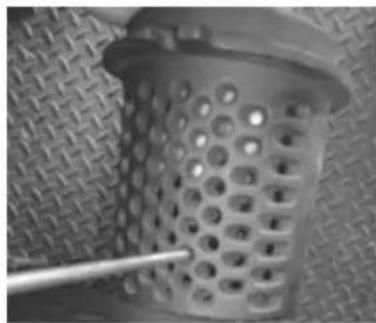
natural_image
Close-up of a perforated metal grate with a rod inserted, placed on a textured surface (no text or symbols visible)c)

natural_image
Close-up of a metal bowl containing a white granular substance with a wooden spoon inserted, no visible text or symbols.d)
Figure 56 - Cleaning the burner and plate
WARNING! the frequency of maintenance tasks is dependent on the quality of pellets
Additional cleaning
Additional cleaning should be carried out for every 2000 Kg of pellets consumed. The boiler's air pipes and respective turbulators must be cleaned. To do this, start by opening the lid located on the top of the unit (Figura 57-a) and removing the six butterfly nuts securing the lower lid (Figura 57-b e c). Next, pull up the turbulators (Figure 57-d), also removing the spring support (Figure 57-f). A vacuum cleaner should be used to clean this area and the interior of the pipes may be cleaned using a steel brush (Figure 57-g) The turbulators and springs previously removed should also be cleaned with a steel brush.
To reinstall the turbulators, execute in reverse the above procedure shown in the figures.

natural_image
Black and white photo of a robotic arm on a dark surface, with no visible text or symbolsc)
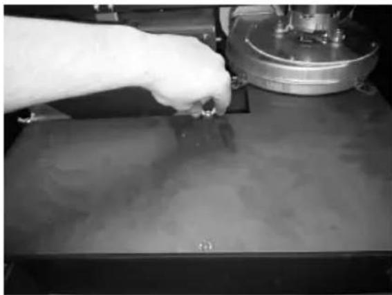
natural_image
Close-up of a gloved hand pressing down on a mechanical component (no visible text or symbols)b)
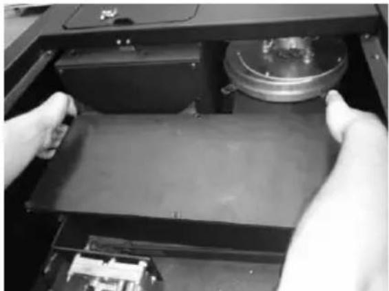
natural_image
Close-up of hands installing or adjusting a mechanical component on an open device (no visible text or symbols)c)
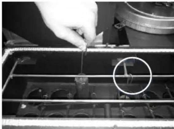
natural_image
Close-up of a hand using a tool to adjust or install electronic components in a device (no visible text or symbols)d)
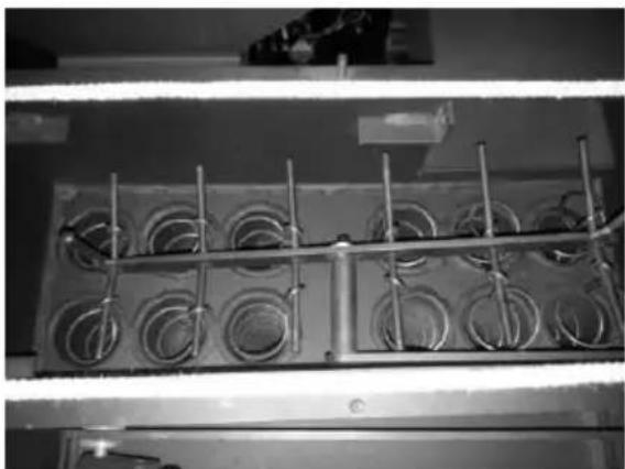
natural_image
Close-up of a metal grate with circular wells and metal rods, no visible text or symbolse)
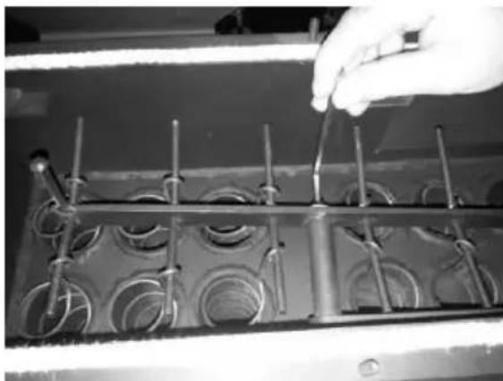
natural_image
Close-up of a hand holding a small object over a grid-like mechanical component (no visible text or symbols)f)

natural_image
Close-up of a hand operating a mechanical device with coiled spring-like components (no visible text or symbols)g)

natural_image
Industrial machine with circular cavities and a cylindrical component inserted into a tray (no visible text or symbols)h)
Figure 57 – Cleaning of air pipes and turbulators
Cleaning the burner and plate
A cleaning the burner and the plate, as shown in the figures, 58-b, 568c and 58-d to prevent obstruction of the holes in the burner or some kind of residue ashes must not be made to be gripped plate cleaning.

natural_image
Interior view of a metal industrial or laboratory facility with a central circular component and a vertical pipe inserted (no visible text or symbols)a)

natural_image
Close-up of a hand pouring liquid into a container (no visible text or symbols)b)
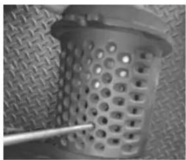
natural_image
Close-up of a perforated metal grate with a metal rod inserted, placed on a textured surface (no text or symbols visible)c)

natural_image
Close-up of a metal pipe with a white tool inside, showing granular material (no text or symbols visible)d)
Figure 58 - Cleaning the burner and plate
In the event that fume extraction is not operating under the best conditions, the extractor should be cleaned as illustrated in Figure 59 and Figure 60. In any case, it is recommended that this procedure be carried out at least once a year.

natural_image
Close-up of a metal bracket with a circular hole and mounting holes, no visible text or symbolsc)

natural_image
Close-up of a mechanical device with a circular hole and metal components, no visible text or symbolsb)
Figure 59 – Remove the screws securing the upper lid, both in the front and back of the boiler, to access the extractor

natural_image
Close-up of a metallic mechanical component with a circular base and central hub (no visible text or symbols)
natural_image
Exterior view of a rectangular concrete block with a circular cutout and a horizontal beam (no text or symbols visible)Figure 60 – Remove the screws of the extractor and vacuum the air flow area
Note: you must annually to check the pre-charge of the expansion vessel, check security valve and the liquid state of the hydraulic circuit.
WARNING! the frequency of maintenance tasks is dependent on the quality of pellets
11. Alarms / failures / recommendation list

| Alarm | Code | Troubleshooting | |
| Ignition failure | A01 | Maximum time 1800 sec | - empty worm drive channel - restart the unit- heater resistor burnt - ignition - replace resistor- linear motor resistor burnt- faulty micro switch- the burning basket has been incorrectly installed- linear cleaning motor is blocked- fume temperature not exceed the activation setting |
| No flame or lack of pellets | A02 | Fume temperature below 45 °C | - Pellet reservoir is empty |
| Excess heat in the pellet drum | A03 | 110 °C | - the fan is not working - call for assistance- faulty thermostat - call for assistance- machine with faulty ventilation |
| Excess fume temperature | A04 | Over 260 °C | - fan not working or set to a low power level - increase the level to maximum (if the problem persists, call assistance)- insufficient extraction- excess of pellets- faulty fume probe |
| Pressure switch alarm | A05 | The door is open, lack of draught or extractor fault for 120 sec | - close the door and clear the error message on the faulty pressure regulator- Obstruction of the exhaust pipe or faulty extractor |
| Air mass probe | A06 | 40 lpm delta for 3600 sec | - pipes with insufficient extraction or obstructed pipes |
| The door is open | A07 | Door open for 120 seconds | - close the door - clear the error message- air mass sensor damaged |
| Fume extractor is faulty | A08 | Connection failure | - check connection- check the smoke extractor is not blocked |
| Fume probe failure | A09 | Connection failure | - check connection- smoke probe damaged |
| Pellet resistance error | A10 | Connection failure | - check connection- resistance damaged |
| Worm drive error | A11 | Connection failure | - check connection- Worm motor damaged |
| Pellet level alarm | A15 | - check connection- put pellets in the external silo (only active in automatic boilers) | |
| Water pressure outside operating range | A16 | - check connection- check pressure in the hydraulic circuit- adjust pressure in the hydraulic circuit (working range 0.5 to 2.9 bar) | |
| Excess water temperature | A18 | 95 °C | - check connection- check if the pump works- purge hydraulic circuit- check if the heat sinks are open |
Table 5 - list of alarms
Important note: all alarms cause the machine to shut down. The alarm must be reset and restarted. To reset the unit, press the "On/Off" button for 10 seconds until the alarm sounds.
- Troubleshooting
| Troubleshooting |
| Maintenance “Service” |
| Air mass probe failure |
| Low pellet level |
| The door is open |
| Air temperature probe failure |
| Water temperature probe failure |
| Water pressure sensor fault |
| Water pressure close to being outside operating range |
Table6 - List of anomalies
⚠️ Important notice: The maintenance anomaly (the "service" message appears on the display) indicates that the unit has exceeded 2100 operating hours. The unit must be serviced; only then hour meter can be restarted (Technical menu) and the warning cleared. This anomaly does not influence the normal operation of the boiler, it is merely a warning.
⚠️ Important notice: when the alarm “A16” is triggered, you can check the pressure reading on the unit. To do so, press the “Mode” button for 10 seconds to access the standard menus. You have a 2-minute window to access the “info usuario” (user info) menu and check the pressure reading at the unit.
⚠️ Important notice: you can only reset error messages that are flashing on the display. If the error message is steady on the display, press the "Mode" button once.
Important notice: the anomalies do not cause the unit to shut down.
WARNING!
In case of an emergency, switch the unit off using the standard shutdown procedure.
! WARNING!
THE UNIT WILL BE HOT DURING OPERATION, SO YOU NEED TO BE ESPECIALLY CAREFUL OF THE DOOR HANDLE.
12. Installation Diagrams
Simple connection only the central heating radiators
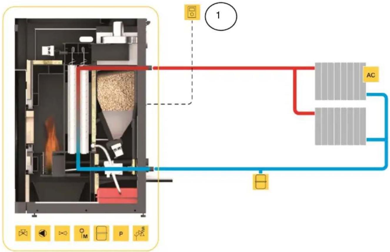
flowchart
graph TD
    A["Input"] --> B["Process Unit"]
    B --> C["AC"]
    C --> D["Output"]
    style A fill:#f9f,stroke:#333
    style B fill:#ccf,stroke:#333
    style C fill:#cfc,stroke:#333
    style D fill:#fcc,stroke:#333
Figure 62 – Simple connection only the central heating radiators
Note:
- The chrono-thermostat should have 1 to 2 °C of hysterisis.
- Hydro independiente "On" (water temperature controlled regulation)
- Modulating pump "On"
- Water sensing inhibition "On"
- Alternative hydro shutdown "On"
- Pump "On" = 50 °C
- Pump "Off" = 50 °C
We can set / change according to the customer's discretion to another temperature.
Connection to central heating radiators and sanitary water combined with solar panel

flowchart
graph LR
    A["Input: Feed, Reactor, Heat Exchanger"] --> B["Process Unit: AC"]
    B --> C["TS"]
    C --> D["AGS"]
    D --> E["Output: Sun"]
    F["Control Valve: PS"] --> G["Valve 1"]
    G --> H["Valve 2"]
    H --> I["Valve 3"]
    I --> J["Valve 4"]
    J --> K["Valve 5"]
    K --> L["Valve 6"]
    L --> M["Valve 7"]
    M --> N["Valve 8"]
    N --> O["Valve 9"]
    O --> P["Valve 10"]
    P --> Q["Valve 11"]
    Q --> R["Valve 12"]
    R --> S["Valve 13"]
    S --> T["Valve 14"]
    T --> U["Valve 15"]
    U --> V["Valve 16"]
    V --> W["Valve 17"]
    W --> X["Valve 18"]
    X --> Y["Valve 19"]
    Y --> Z["Valve 20"]
Figure 62 – Connection to central heating radiators and sanitary water combined with solar panel
Example: electrical connection of a thermostat (ambient air monitoring) of a differential thermostat connected to the deposit and three-way valve to a relay box

Figura 63 – electrical connection of a thermostat (ambient air monitoring) of a differential thermostat connected to the deposit and three-way valve to a relay box
Connection to central heating radiators with another boiler support and sanitary water combined with solar panel

flowchart
graph TD
    A["Material Input"] --> B["D1"]
    B --> C["D2"]
    C --> D["AC"]
    D --> E["ACS"]
    E --> F["Output"]
    G["Sun Source"] --> H["Control Valve"]
    H --> I["Valve 7"]
    I --> J["Valve 8"]
    J --> K["Valve 9"]
    K --> L["Valve 10"]
    L --> M["Valve 11"]
    M --> N["Valve 12"]
    N --> O["Valve 13"]
    O --> P["Valve 14"]
    P --> Q["Valve 15"]
    Q --> R["Valve 16"]
    R --> S["Valve 17"]
    S --> T["Valve 18"]
    T --> U["Valve 19"]
    U --> V["Valve 20"]
    V --> W["Valve 21"]
    W --> X["Valve 22"]
    X --> Y["Valve 23"]
    Y --> Z["Valve 24"]
    Z --> AA["Valve 25"]
    AA --> AB["Valve 26"]
    AB --> AC["Valve 27"]
    AC --> AD["Valve 28"]
    AD --> AE["Valve 29"]
    AE --> AF["Valve 30"]
Figura 64 – Connection to central heating radiators with another boiler support and sanitary water combined with solar panel
Note:
- The chrono-thermostat Earth leakage must have a hysterisis of 15 to 25 °C. ①
- Hydro independiente "Off" (water temperature controlled regulation), put the boiler in "manual" mode and power nivle to "5"
- Modulating pump "On"
- Water sensing inhibition "On"
- Alternative hydro shutdown "On"
- Pump "On" = 50 °C
- Pump "Off" = same or thermostat temperature 1 °C below the temperature differential thermostat
When using the generator with differential thermostat the machine must be connected in the CONNECTION "Remote".
Calculation deposits of inertia: the boilers for pellets is recommended that the buffer tank has 20l/kW.
Connecting underfloor heating in conjunction with another boiler support and sanitary water combined with solar panel

flowchart
graph TD
    A["Input: Feed, Pump, Roast"] --> B["Process Unit"]
    B --> C["Chamber"]
    B --> D["PR"]
    B --> E["AQS"]
    C --> F["Output: Control Valve"]
    D --> G["Control Valve"]
    E --> H["Control Valve"]
    F --> I["Output: Power Supply"]
    G --> J["Power Supply"]
    H --> K["Output: Power Supply"]
    style A fill:#f9f,stroke:#333
    style B fill:#ccf,stroke:#333
    style C fill:#cfc,stroke:#333
    style D fill:#fcc,stroke:#333
    style E fill:#cff,stroke:#333
    style F fill:#ffc,stroke:#333
    style G fill:#ffc,stroke:#333
    style H fill:#ffc,stroke:#333
    style I fill:#fff,stroke:#333
    style J fill:#fff,stroke:#333
    style K fill:#fff,stroke:#333
    style L fill:#fff,stroke:#333
Figura 65 – Connecting underfloor heating in conjunction with another boiler support and sanitary water combined with solar panel
Simbology

Figura 66 – Simbology
17. Electrical diagram of the pellet-run boiler
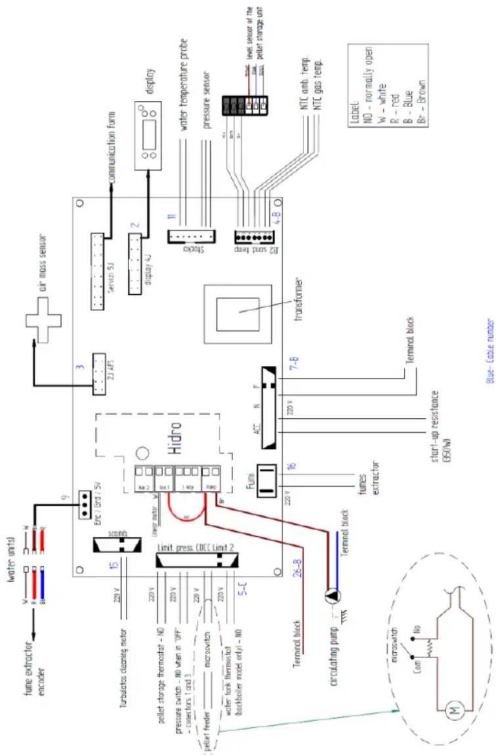
Figure 67 – Electrical diagram of the circuit board

Figure 68 – Electrical diagram of the external silo's circuit board

b) Figure 69 – Level sensor
18. UPM3 25-70 (130 mm) circulating pump
Circulating pump performance graph

line
| Q (m³/h) | H (mca) | | -------- | ------- | | 0 | 7.0 | | 1 | 6.8 | | 2 | 5.0 | | 3 | 3.0 | | 4 | 1.0 |Figure 70 – Circulating pump performance graph
19. Life cycle of a pellet-run boiler
About 90% of the materials used in the manufacture of these units are recyclable, thus contributing towards a reduced environmental impact and the sustainable development of our planet. As such, units that have reached their end of useful life should be delivered to authorised waste operators. It is advised to contact your local authorities for the appropriate collection instructions.
20. Glossary
Ampere (A): SI unit of measurement of electric current
bar: unit of pressure equal to exactly 100,000 Pa. This pressure is very close to standard atmospheric pressure.
cal(Calorie): equal to the amount of heat required to increase the temperature of one gram of water by one degree centigrade.
cm (centimetres): unit of measurement.
CO (carbon monoxide): Lightly flammable, colourless, odourless and very dangerous gas, due to its toxicity.
CO2 (carbon dioxide): Gas needed by plants for photosynthesis on the one hand, and emitted into the atmosphere on the other, contributing to the greenhouse effect.
Combustion: a process for obtaining energy. Combustion is basically a chemical reaction that requires three items in order to take place: fuel, oxidant and ignition temperature.
Oxidiser: chemical substance used for combustion (essentially oxygen) which is required for it to take place.
Combustible: anything that can undergo combustion, in this case referring to wood.
Creosote: chemical compound created by combustion. This compound is sometimes deposited on the glass and shaft of the heating recovery unit.
Circuit breaker: Electromechanical device that protects a given electrical appliance.
Energy Efficiency: capacity to generate large quantities of heat with the least amount of energy possible, causing the least environmental impact and reducing the energy budget.
CO Emissions: emission of carbon monoxide gas into the atmosphere.
CO emissions (13% of O2 ): carbon monoxide content corrected to 13% of O2 .
Differential Switch: protects people and property against grounding failures, preventing electric shocks and fires.
kcal (Kilocalorie): multiple unit of measurement of calories. Equivalent to 1000 calories.
kW (Kilowatt): Unit of measurement equal to 1000 watts.
mm (millimetres): unit of measurement.
mA (milliampere): unit of measurement of electric current.
Pa (Pascal): standard IS unit of pressure and tension. This unit is named after Blaise Pascal, an eminent French mathematician, physicist and philosopher.
Net Heating Value: also known as specific combustion heat. It represents the amount of heat released when a certain amount of fuel is completely burned. Net heating value is expressed in calories (or kilocalories) per unit of weight of fuel.
Rated power: Electrical power consumed from the energy source. Measured in watts.
Rated net heating value: heating capacity, i.e. the heat energy the unit transfers from energy present in the firewood – measured for a standard load of firewood over a given period of time.
Power output: a manufacturer's recommendation from tests on the equipment with firewood loads within a reasonable operating range. This power output range will present different firewood consumptions per hour.
Plumb: vertically above the installation.
Performance: expressed as a percentage of “useful energy” that can be extracted from a given system, taking into account the “total energy” of the fuel used.
Ignition temperature: temperature above which the fuel can enter into combustion.
Thermoresistant: resistant to high temperatures and thermal shock.
Glass ceramics: highly resistant ceramic material produced through controlled crystallisation of vitreous materials. Used widely in industry.
W(Watt): IS unit of power.
BAXI
Tel. + 34 902 89 80 00
www.baxi.es
informacion@baxi.es
BAXI

- EN
- Comando
- Comando e display
- Limpeza Queimador
- Contents
- Package content
- Unpacking the Boiler
- Safety precautions
- For your safety, we recommend that:
- Technical specifications
- Installation of the pellet-run boiler
- Installation requirements
- Warning!
- Installation of pipes and fume exhaust systems:
- Installation without a shaft
- Installation with a shaft
- Hydraulic Installation
- Operating mode for radiator/Buffer tank
- Fuel
- Use of the pellet-run boiler
- Recommendations
- Remote Control
- Remote control and display
- Display information summary
- Menu
- Water temperature
- Date/Time
- Timer
- Sleep
- Configuration menu
- User Info
- Stoppage
- Turn off the unit
- Instructions for removing the side covers
- Remove side covers
- Pellet reservoir lid
- Filling the pellet reservoir
- Installation and operation using remote command (chrono-thermostat) – not included with the boilers
- Instructions for remote control assembly
- Installation of the external silo
- Description of operation
- Adjusting the height of the boiler
- Adjusting the sensor's response time and sensitivity
- Installing the storage unit on the right side of the boiler
- Installing the storage unit on the left side of the boiler
- Enabling the pellet level sensor
- Boiler startup
- Maintenance
- weekly maintenance
- Cleaning the burner and plate
- WARNING! the frequency of maintenance tasks is dependent on the quality of pellets
- Additional cleaning
- Alarms / failures / recommendation list
- - Troubleshooting
- Installation Diagrams
- Simple connection only the central heating radiators
- Note:
- Connection to central heating radiators with another boiler support and sanitary water combined with solar panel
- Simbology
- Electrical diagram of the pellet-run boiler
- UPM3 25-70 (130 mm) circulating pump
- Life cycle of a pellet-run boiler
- Glossary
Brand : Baxi
Model : CBP Matic 18
Category : Central heating boiler