
18 OV - Water heater DIMPLEX - Free user manual and instructions
Find the device manual for free 18 OV DIMPLEX in PDF.


| Brand | Dimplex |
| Model | 18 OV |
| Product Type | Electric Water Heater |
| Capacity | 18 Liters |
| Power Consumption | 2000 W |
| Voltage | 220-240 V |
| Frequency | 50/60 Hz |
| Dimensions (H x W x D) | 600 x 350 x 350 mm |
| Weight | 10 kg |
| Temperature Range | 30-75 °C |
| Thermostat Type | Adjustable with safety cutoff |
| Safety Features | Overheat protection, pressure relief valve |
| Heating Element | Copper sheathed, 2000 W |
| Installation Type | Wall-mounted or floor-standing |
| Water Connection | 1/2 inch BSP |
| Energy Efficiency Class | B |
| Standby Heat Loss | 0.5 kWh/24h |
| Warranty | 2 years |
| Maintenance | Annual descaling recommended |
| Repairability | Replaceable heating element and thermostat |
Frequently Asked Questions - 18 OV DIMPLEX
User questions about 18 OV DIMPLEX
0 question about this device. Answer the ones you know or ask your own.
Ask a new question about this device
Download the instructions for your Water heater in PDF format for free! Find your manual 18 OV - DIMPLEX and take your electronic device back in hand. On this page are published all the documents necessary for the use of your device. 18 OV by DIMPLEX.
USER MANUAL 18 OV DIMPLEX
Dimplex 18 0V Dimplex 32 0V
Open Vented Condensing Boilers
natural_image
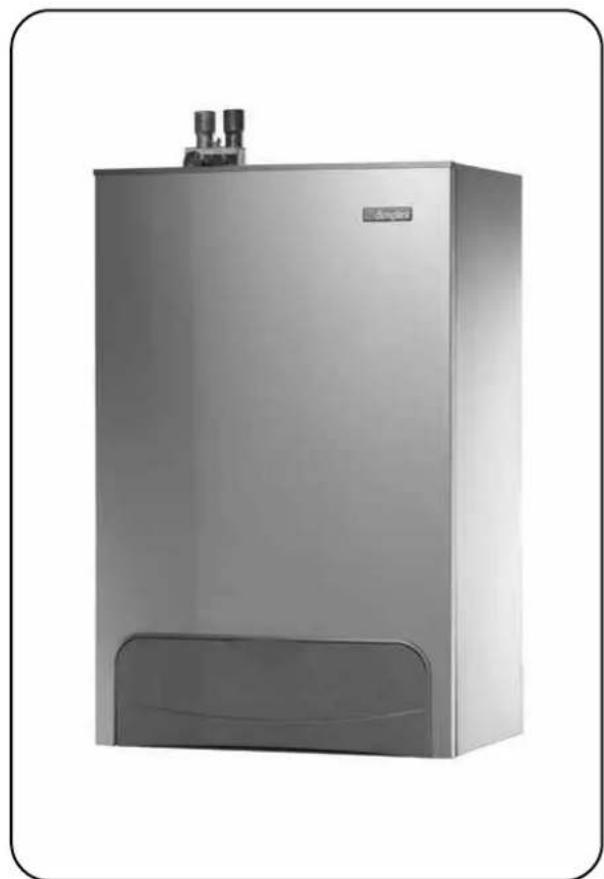
Exterior view of a modern stainless steel water heater unit (no visible text or symbols)User's Operating Instructions
These instructions should be left with the user
SECTION DESCRIPTION PAGE
1.0 Using the Boiler 3
2.0 Problem Solving 4
3.0 Safety 5
4.0 Error Codes 6
5.0 Additional Information 7
Read these instructions carefully before trying to operate the appliance.
GAS COUNCIL NUMBERS
Natural Gas
Dimplex 18 OV - Gas Council Appliance No: 41 149 04
Dimplex 32 OV - Gas Council Appliance No: 41 149 03
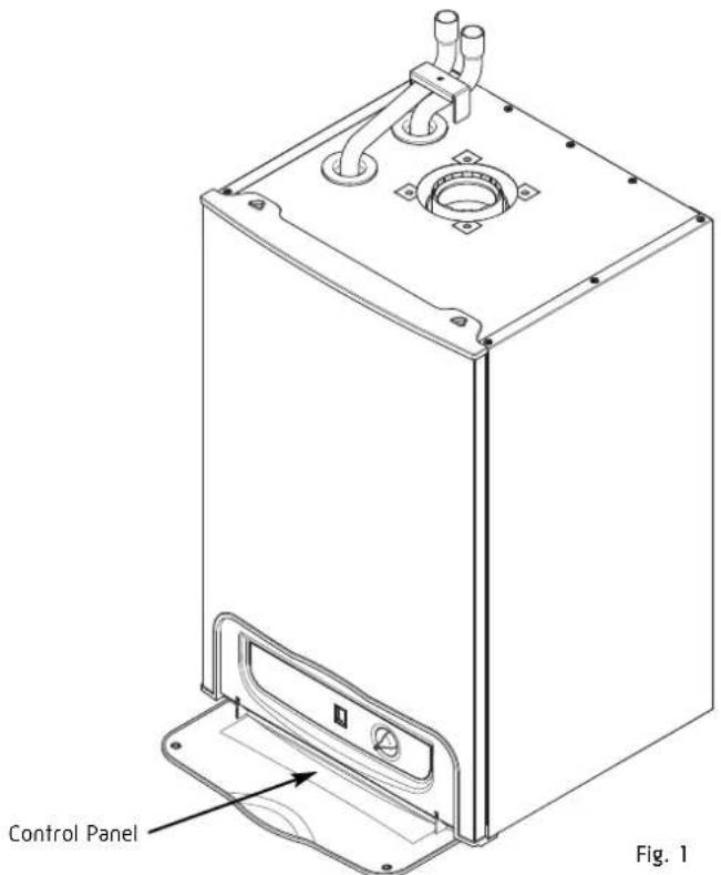
1.1 CONTROL PANEL
Fig. 2
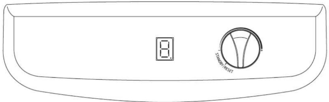
7 segments
LED display
Central Heating
Temperature Control
1.2 CH - CENTRAL HEATING TEMPERATURE CONTROL
Control knob shown in the OFF position.
Turn the knob clockwise to increase the temperature of the central heating.
- Switch on the electrical supply.
- Turn the CH temperature Control knob to the midpoint between the minimum and maximum setting. The display changes from 'O' to 'h'.
- Ensure Programmer and room thermostat (if fitted) are calling for heat.
- The display changes to 'H'. When the boiler has lit a small dot will also appear in the bottom right corner of the display.
- If the burner fails to light the fan will stop. Initially this may be due to air in the gas supply. The boiler will automatically have five attempts at ignition.
- After the five attempts it may be necessary to RESET the boiler by turning the control knob to the RESET/STANDBY position and back to 'ON' within TWO seconds (then repeat step 2).
1.4 CH - CENTRAL HEATING TEMPERATURE CONTROL
Adjustable via the CH temperature control knob to give radiator temperatures of between 30°C and 80°C.
During periods of no central heating requirement, the control should be set to the STANDBY position but the permanent live to the boiler should be left on.
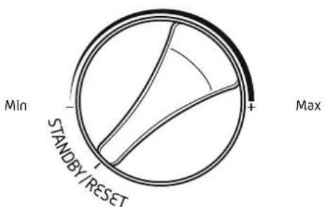
Fig. 3
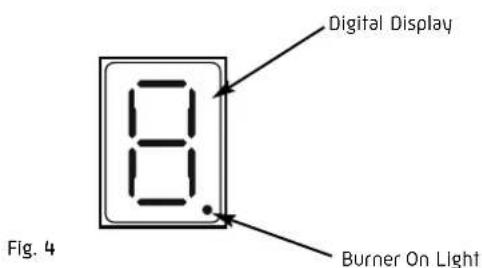
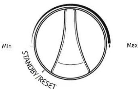
Fig. 5
2.1 STEP BY STEP GUIDE
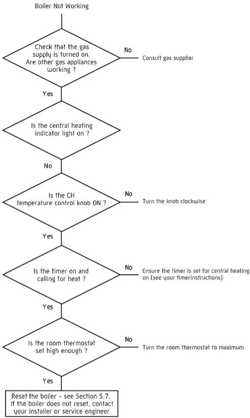
flowchart
graph TD
    A["Boiler Not Working"] --> B{Check that the gas supply is turned on. Are other gas appliances working?}
    B -->|No| C["Consult gas supplier"]
    B -->|Yes| D{Is the central heating indicator light on?}
    D -->|No| E{Is the CH temperature control knob ON?}
    D -->|Yes| F{Is the timer on and calling for heat?}
    E -->|No| G["Turn the knob clockwise"]
    E -->|Yes| H{Is the room thermostat set high enough?}
    H -->|No| I["Ensure the timer is set for central heating on [see your timerinstructions"]]
    H -->|Yes| J{Is the room thermostat to maximum?}
    J -->|No| K["Turn the room thermostat to maximum"]
    J -->|Yes| L["Reset the boiler – see Section 5.7. If the boiler does not reset, contact your installer or service engineer"]
3.1 GENERAL SAFETY
DO NOT interfere with any sealed components and use the appliance only in accordance with these instructions.
This appliance is not intended for use by persons (including children) with reduced physical, sensory or mental capabilities, or lack experience and knowledge, unless they have been given supervision or instructions concerning use of the appliance by a person responsible for their safety. Children should be supervised to ensure that they do not play with the appliance.
3.2 CURRENT GAS SAFETY (INSTALLATION & USE) REGULATIONS
It is the law that all gas appliances are installed by a competent person in accordance with the above regulations. Failure to install appliances correctly could lead to prosecution. It is in your own interest, and that of safety, to ensure that the law is complied with. If the appliance is damaged, turn off the appliance and consult a CORGI registered installer. If it is known or suspected that a fault exists on the appliance it MUST NOT be used until the fault has been rectified by a competent person.
3.3 ELECTRICAL SUPPLY
This appliance must be earthed.
Supply: 230V - 50Hz fused at 3A.
The method of connection to the mains supply must facilitate complete isolation of the appliance. Either a 3A fused three pin plug and unswitched shuttered socket outlet, or a 3A fused double pole switch having a 3mm contact separation in both poles, serving only the boiler (and its external controls), may be used.
3.4 CLEARANCES AND VENTILATION
- A flat vertical area is required for the installation of the boiler.
- Where an open flued (B23) system is used then an air vent must be provided in the same room or internal space of the flue duct air inlet, with a minimum free area of:
Dimplex 18 = 60cm²
Dimplex 32 = 125cm²
- These dimensions include the necessary clearance around the boiler for case removal, spanner access and air movement. Additional clearances may be required for the passage of pipes around local obstructions such as joists running parallel to the front face of the boiler.
- When installed in a cupboard or compartment it is not permissible to store other objects in the cupboard. Additionally no flammable objects/items must be allowed to come into contact with the boiler.
- The boiler does not require additional ventilation when it is installed in a cupboard or compartment. The exception to this is where an open flue system has been installed - See note 2.
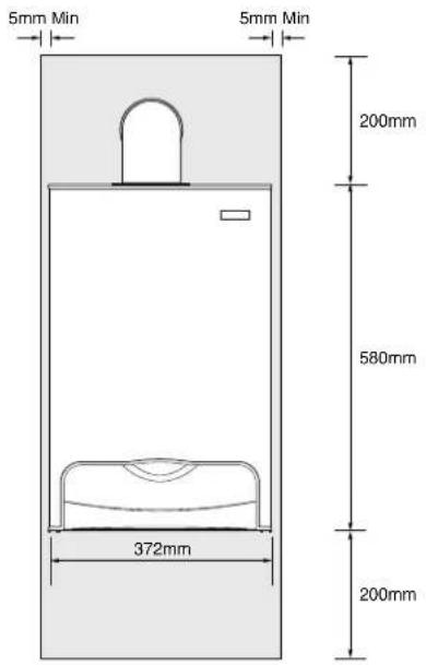
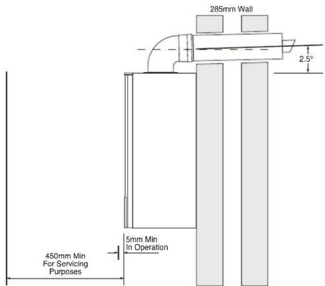
Fig. 11
AFTER ENSURING THAT ALL ACTIONS HAVE BEEN CARRIED OUT RESET THE BOILER (REFER TO SECTION 5.4) IF ANY OF THE BELOW FAULTS OCCUR DURING INSTALLATION PLEASE REFER TO THE ACTIONS HOWEVER VERIF ANY OTHER ERROR CODE IS SHOWING PLEASE CONTACT THE INSTALLER OR TECHNICAL HELP LINE: 01926 834834
RESET LOCK-OUT CODES
| ERROR CODE | DESCRIPTION | REASON | ACT D N | RESET POSSIB LE |
| 1 Overheated | CH Water temperature appliance greater than 105°C | Check no air is in heat exchanger / CH systemCheck external pump operation YesCheck PCB / X1C connectorCheck flow thermistorCheck wires to sensors not crossed | ||
| 2 | Different check faulty / Flame for 15 seconds | Sensor temperature differential incorrect | Check water pressureCheck external pump / CH system blockageCheck no air is in heat exchanger / CH systemCheck flow, and return sensors | Auto Restart When Fixed |
| 3 No gas or Lockout | Lockout flame Low gas pressure signal / No flame, Lockout after 5 ignition attempts | Loss of flame signal during operation | supplyCheck gas service cockCheck gas valve and leadCheck detection electrode / leadCheck PCB / X2A & X2B connectorsCheck spark generator /spark electrodeCheck mains earth lead continuity | Yes |
| 4 | Flue gas sensor / No flame | Flue gas temperature greater than 95°C | Check flue sensorCheck flue systemCheck no air is in heat exchanger / CH systemCheck external pumpCheck PCB / PCB connectors | Yes |
BLOCKING CODES
| ERROR CODE | DESCRIPTION | REASON | ACT D N | RESET POSSIB LE |
| 5 | Defective sensor or thermal fuse blown | Defective flow, return or flue sensor or heat exchanger reached maximum safe working temperature | Check wiring to sensorsCheck PCB / X6 & X8 connectorsCheck flow, return and flue sensorsCHECK THERMAL FUSE IS OPEN CIRCUIT. IF SO REPLACE HEAT EXCHANGER (SEE 10.8) | Auto Restart When Fixed |
| 6 | Defective gas valve / Flame continues after demand ends | 5 sec flame signal after burner is switched off | Check gas valve and leadCheck PCB | |
| 7 Defective fan / No flame Missing or Erroneous RPM signal | Erroneous RPM Signal | Check fan | Check mains fan lead & connectorCheck low voltage fan lead & connectorCheck PCB / X3 connector | |
| A | PCB error / No flame | Internal error | Check PCB | |
| b | Activate BCC / No flame | New BCC | Turn CH control knob to reset twice to activate | |
| C Safety system failure / Failure of internal self checking system | Failure of internal self | Check PCB | Check BCC is initialised | |
| E | BCC error / No flame | Incorrect / missing BCC | Reset or replace BCC | |
| h No flame | Faulty connector | Check PCB | / X1A connector | |
| O | Different check faulty / Flame for 15 seconds | Water flow rate too low | Check water pressureCheck external pump / CH system blockageCheck no air is in heat exchanger / CH systemCheck wires to sensors not crossedCheck flow, and return sensors | |
| P | Error in power supply / No flame | Low mains voltage | Check mains voltageCheck PCB connectors | |
| No light indication | Defective power supply | Check power supplyCheck PCB / X1B connectorCheck PCB fuse |
5.1 BOILER LOGBOOK
The logbook is included inside the Installation instructions. This logbook should be completed by your installer to verify that the correct installation and commissioning procedure was followed.
Failure to complete the logbook may result in difficulties should a problem arise with your appliance during the guarantee period.
This logbook forms part of the industry's Benchmark code of practice for the installation, commissioning and servicing of central heating systems.
All CORGI registered installers carry a CORGI identification card and have a registration number. You can check your installer is registered by telephoning 0870 4012300 or writing to:-
1 Elmwood
Chineham Business Park
Crockford Lane
Basingstoke
RG24 8WG
or check online at www.corgi-gas-safety.com
These appliances meet the requirements of;
Gas Appliance Directive 90/396/EEC
Efficiency of Hot Water Boilers Directive 92/42/EEC
Low Voltage Directive 92/42/EEC
Electromagnetic Compatibility Directive 92/31/EEC
Type test certified by:- Notified Body 0087 (Pin 87BT49).
Product/Production certified by:
Notified Body 0086.
For GB/IE only.
5.2 GENERAL CARE
The front panel should be cleaned with a damp cloth and mild detergent. Do not use abrasive cleaners.
5.3 ROUTINE SERVICING
To ensure continued efficient operation of the appliance, it is recommended that it is checked and serviced as necessary at regular intervals. The frequency of servicing will depend upon the particular installation conditions and usage but in general once a year should be adequate. It is law that any service work must be carried out by a competent person such as British Gas or other CORGI Registered personnel.
5.4 EMERGENCY
WARNING - If a gas leak is suspected or exists, turn the gas OFF at the incoming mains (adjacent to the meter). Do not operate any electrical switches. Do not operate any electrical appliances. Open all windows and doors. Do not smoke. Extinguish all naked lights. Phone the Transco 24 hour emergency number immediately on 0800 111 999 (Do not call from a mobile phone).
5.5 PLUMING FROM TERMINAL
Like all condensing boilers this appliance will produce a plume of condensation from the flue terminal. This is due to the high efficiency and hence low flue gas temperature of the boiler. It is normal and not a fault indication.
The boiler is fitted with a condensate trap.
The condensate drain point must not be modified or blocked (see section 7.6 of the installation manual).
5.6 TO TURN THE BOILER OFF
For short or long periods
Switch the programmer and/or room thermostat switch to the OFF position.
NOTE: The appliance is fitted with a frost protection device in the event of very cold conditions. Providing there is mains power supply to the appliance, the frost protection mode is integral. If the system temperature falls below 5°C then the boiler will fire on its minimum setting until a flow temperature of 30°C is reached. Further protection can be incorporated by using a system frost thermostat.
The pump will automatically operate for 1 minute in every 24 hours to prevent sticking.
5.7 BOILER OVERHEAT PROTECTION
In the event of overheating, the boiler will shut down and the digital display will show '1'. Allow the boiler to cool, then briefly turn the CH control knob fully anti-clockwise to the RESET/STANDBY position and then back to 'ON' within two seconds.
If the fault persists, consult a CORGI Registered installer.
dimplex
Dimplex Boilers
20/22 First Avenue
Bluebridge Industrial Estate
Halstead
Essex C09 2EX
Telephone Sales and Service: 0844 371 1121
Fax: 01787 474588
e-mail:
sales@dimplexboilers.co.uk
enquiries@dimplexboilers.co.uk
training@dimplexboilers.co.uk
website:
www.dimplexboilers.co.uk
Dimplex Boilers is continually improving its products and therefore reserve the right to change product specifications without prior notice. Errors & omissions excepted.
SALES AND SERVICE HELPLINE: 0844 371 1121
- Dimplex 18 0V Dimplex 32 0V
- GAS COUNCIL NUMBERS
- CONTROL PANEL
- CH - CENTRAL HEATING TEMPERATURE CONTROL
- CH - CENTRAL HEATING TEMPERATURE CONTROL
- STEP BY STEP GUIDE
- GENERAL SAFETY
- CURRENT GAS SAFETY (INSTALLATION & USE) REGULATIONS
- ELECTRICAL SUPPLY
- CLEARANCES AND VENTILATION
- AFTER ENSURING THAT ALL ACTIONS HAVE BEEN CARRIED OUT RESET THE BOILER (REFER TO SECTION 5.4) IF ANY OF THE BELOW FAULTS OCCUR DURING INSTALLATION PLEASE REFER TO THE ACTIONS HOWEVER VERIF ANY OTHER ERROR CODE IS SHOWING PLEASE CONTACT THE INSTALLER OR TECHNICAL HELP LINE: 01926 834834
- BOILER LOGBOOK
- GENERAL CARE
- ROUTINE SERVICING
- EMERGENCY
- PLUMING FROM TERMINAL
- TO TURN THE BOILER OFF
- BOILER OVERHEAT PROTECTION
- dimplex
Brand : DIMPLEX
Model : 18 OV
Category : Water heater