DVES95 - Water heater DIMPLEX - Free user manual and instructions
Find the device manual for free DVES95 DIMPLEX in PDF.

User questions about DVES95 DIMPLEX
0 question about this device. Answer the ones you know or ask your own.
Ask a new question about this device
Download the instructions for your Water heater in PDF format for free! Find your manual DVES95 - DIMPLEX and take your electronic device back in hand. On this page are published all the documents necessary for the use of your device. DVES95 by DIMPLEX.
USER MANUAL DVES95 DIMPLEX
natural_image
Line drawing of a showerhead and BCDimplex® remote device (no text or symbols on the devices themselves)Installation and User Guide
IMPORTANT:
This booklet should be left with the user after installation and demonstration
Contents
Installation Guide
| 1 – Pack Contents 3 |
| 2 – Installation Check List 3 |
| 3 – Important Safety Information 4 |
| 4 – General Installation Layout Guide 5 |
| 5 – Important Installation Information 6 |
| 6 – Fixing the Shower to the Wall 6 |
| 7 – Product Positioning Guide 7 |
| 8 – Plumbing Connections 8 |
| 9 – Electrical Connections 9-10 |
| 10 – Fitting the Front Cover 10 |
| 11 – Riser Rail Fitting Instructions 11 |
| 12 – Commissioning the Shower 12 |
| 13 – Troubleshooting Checklist for the Installer 13 |
User Guide
| 1 – Important Safety Information 14 | |
| 2 – Operating the Shower 15 | |
| 3 – How Your Shower Works | 16 |
| 4 – Routine Maintenance | 16 |
| 5 – Troubleshooting and FAQs | 17 |
| 6 – Troubleshooting Checklist for the Installer | 18 |
| 7 – Energy Related Product Directive (ErP) | 19 |
IMPORTANT: This appliance can be used by children aged from 3 years and above and persons with reduced physical, sensory or mental capabilities or lack of experience and knowledge if they have been given supervision or instruction concerning use of the appliance in a safe way and understand the hazards involved.
The shower spray head MUST be cleaned regularly to remove scale and debris. The frequency of the cleaning will vary according to the local water quality. If the water outlet temperature becomes hot and you are unable to obtain cooler water, immediately check the shower handset for blockage. See User Guide Section 4 for cleaning instructions.
Do not operate shower if frozen, or suspected of being frozen. It must thaw out before using.
1. Pack Contents
Please make sure ALL components are included before starting the installation.
□ Shower Unit
□ Shower Handset
□ Riser Rail Tube
☐ Riser Rail Brackets x 2
☐ Riser Rail Height Adjuster
□ Flexible Shower Hose
Soap Dish
□ Screw Pack
□ Installation and User Instructions
2. Installation Check List
☐ Check that the water supply will satisfy requirements
☐ Check that water & cable entry points of the unit meet requirements
☐ Check that the electric supply will satisfy requirements
□ Select a suitable position for the shower
☐ Follow plumbing installation section
☐ Follow electrical installation section
☐ Fit to the wall & connect the shower supplies
☐ Commission the shower in the way described
☐ Fit the front cover & aligning the controls
☐ Familiarise yourself with the user operating instructions
3. Important Safety Information
Products manufactured by Redring Xpelair Group are safe and without risk provided they are installed, used and maintained in good working order in accordance with our instructions and recommendations.

MAINS SERVICE CONNECTIONS: The shower unit is supplied for right entry and left entry, please see Section 8 & 9 for "Plumbing Connections" & "Electrical Connections" for installation information.

IMPORTANT: To comply with water regulations, building regulations or any specific local water company regulations and in accordance with BS EN 806 a double check valve should be fitted where it is possible that the shower head may come into contact with used water, for example in the bath or a shower tray.

IMPORTANT: Check that there are no hidden cables or pipes before drilling holes for the wall plugs. Choose a flat piece of wall to avoid the possibility of distorting the back plate and making the front cover a poor fit. Exercise great care when using power tools near water. The use of a residual current device (RCD) is recommended.

IMPORTANT: Before connecting the water supply to the shower unit the water supply pipe should be flushed out to remove all debris. After flushing the pipework make the connection to shower inlet and ensure the shower is positioned squarely on the wall and all fixing screws are tightened.

IT IS VERY IMPORTANT: To ensure that the terminal block screws are fully tightened and that no cable insulation is trapped under screws, and tighten periodically in accordance with BS 7671. The earth continuity conductor of the electrical installation must be effectively connected to all exposed metal parts of other appliances and services in the room in which the shower unit is installed to conform with BS 7671. The unused supply terminal block must not be used for any other purpose.

IMPORTANT: Ensure that the temperature control knob is turned to MIN temperature (FULL flow) and the commissioning instructions are followed before switching the unit on. This will make sure that the unit is full of water when first activated.

IMPORTANT: The shower unit MUST be full of water before the heat settings are changed.

IMPORTANT: The shower unit MUST be fitted with a WRAS (Water Regulations Advice Scheme) listed mains water isolating valve.
4. General Installation Layout Guide
- Plan your installation carefully. Check on the nearest and most accessible rising main water supply, this may be beneath the bath or in the loft, where it feeds the water storage tank. Use only the cold rising water main.
-
If possible avoid connecting the shower unit where it will be affected by water drawn off by another appliance.
-
For example the mains feed to a toilet as this may cause a drop in pressure to a level that is too low for the shower unit to work correctly.
- A WRAS (Water Regulations Advice Scheme) listed isolating valve must be fitted between the rising main and the unit to comply with water regulations and to allow for routine maintenance and servicing.

flowchart
graph TD
    A["Separation Unit"] --> B["SEPARATE PERMANENTLY CONNECTED CONSUMER UNIT"]
    B --> C["CEILING JOISTS"]
    C --> D["BATHROOM"]
    D --> E["FLOOR"]
    E --> F["COLD WATER MAINS SUPPLY"]
    G["ELECTRICAL ISOLATION SWITCH IN ACCORDANCE WITH I.E.T BS 7671"] --> H["Main Water Isolating Tap"]
    H --> I["BATH"]
    I --> J["FLOOR"]

IMPORTANT!

This appliance can be used by children aged from 3 years and above and persons with reduced physical, sensory or mental capabilities or lack of experience and knowledge if they have been given supervision or instruction concerning use of the appliance in a safe way and understand the hazards involved.
5. Important Installation Information
Shower installation must be carried out by a suitably qualified person and be in accordance with BS 7671 (IET wiring regulations), building regulations, water regulations and / or any specific local water company regulations in force and should be in accordance with BS EN 806.
- This shower unit is designed to be connected to a 15mm cold water mains supply.
- To make sure the heating elements are activated the shower must be connected to mains water supply with a minimum static pressure of 0.1MPa (15lb/sq in) – 1 bar at a minimum flow rate of 8 litres per minute. The maximum static pressure is 1MPa (145lb/sq in) 10 bar.
-
The shower unit must not be fitted where it may be exposed to frost, for example, in an outdoor area. The shower must not be used if suspected of being frozen. Frost damage is not covered by the guarantee.
-
Plumbers jointing compound must not be used. In instances of difficult joints use P.T.F.E. Tape. The use of jointing compound will invalidate the product guarantee.
- Do not solder fittings near the shower unit as heat can travel along pipe work and damage components.
- Do complete all plumbing connections before making the electrical connections.
NOTE: For the 9.5 & 10.5kW model, the minimum running pressure must be obtained at 9 L/min.
6. Fixing The Shower To The Wall
- Position your shower on a FLAT section of wall, ensuring that it will NOT be in the direct water spray from the shower handset when fixed.
- The shower unit should be positioned so that the shower handset cannot be immersed in the bath or shower tray when hanging down.
-
Remove the four front cover fixing screws and lift the cover off complete with the control knobs and start / stop push button.
-
Having decided on the water and cable entry points and chosen a flat piece of wall, hold the shower vertically against the wall and mark the top two fixing holes whilst ensuring the shower is square.
-
Carefully drill the two holes as marked using a sharp 5.5mm masonry drill after first making certain there are no pipes or wires behind the proposed holes.
-
Insert the wall plugs and screws provided leaving the screw head proud by approximately 5mm. The shower can now be hung on these screws.
-
Make sure that the shower is positioned vertically and square, now mark and drill the lower slotted fixing hole. Then fix the shower to the wall. Do not fully tighten the screws at this stage
-
The shower back plate and removable corner mouldings have moulded cut out sections which are clearly indicated to allow the chosen service entry option to be cut out prior to final fix.
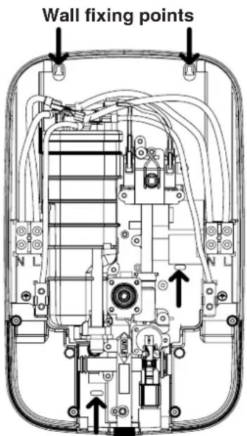
text_image
Wall fixing pointsNOTE: The bottom screw should only be fitted during final installation.
TIPS
- A piece of insulating or masking tape applied to the wall before marking out the fixing holes will help stop the drill from wandering, particularly on tiled surfaces.
- When working near a basin or bath, insert the plug in the waste fitting so that small parts cannot be lost.
• Take care not to drop accessories or tools into basin or bath.

IMPORTANT

Under no circumstances should this shower unit be recessed (it must be fitted onto the finished wall surface) or tiled up to or sealed around the unit at this may prevent air circulating and any condensation escaping. Shower must be installed on a flat wall.
7. Product Positioning Guide

text_image
Shower unit can be mounted either side of riser rail. Height of shower handset and shower to suit user's requirements Soap dish Hose retaining ring 25mm minimum Spillover level Outline of bath or shower tray Spillover level8. Plumbing Connections
The shower back plate incorporates into the lower right and left side a removable corner section to allow easy access when deciding on and connecting to the water mains supply.
- Remove the bottom right or left hand side corner section giving access to the water inlet connection point.
IMPORTANT: Before connecting the mains water supply to the shower flush out the pipe work to remove all swarf and system debris. This is achieved by connecting a suitable hose (i.e. Garden hose) to the pipe work and turning on the mains water supply at the isolating stop tap long enough to clear the debris to waste.
-
Turn off the mains water supply at the isolating stop tap.
-
Having decided on the direction of the water inlet supply: Top (falling) Bottom (rising) or rear / side inlet it is necessary to remove the appropriate knock out (thinned out plastic) cross section from the back plate before commencing with the installation. The connection to the unit is made using a 15mm copper, stainless or plastic pipe with a 15mm compression elbow or 15mm push fit elbow.
IMPORTANT: Do not use excessive force when making the connection to the unit.
-
If left hand water entry is desired, remove spring clip and then blanking cap. Replace blanking cap onto right spigot, ensuring it is fully seated, then snap spring clip back into groove for retainment.
-
Now tighten the back plate fixing screws so the unit is firmly fixed to the wall.
- If rear entry pipe work is used we recommend the use of a suitable sealant to seal around the incoming pipe work to prevent water entering the wall.
- Turn on the mains water supply and check for leaks, paying particular attention to the water inlet connections. At this stage no water can flow through the unit.
IMPORTANT: Remember to replace the lower corner section before refitting the front cover.
Top cut-out section for mains water and cable entry.
Top cut-out section for mains water and cable entry.

text_image
Water inlet's. Side cut-out section for mains water entry only.Bottom cut-out section for mains water and cable entry.
Side cut-out section for mains water entry only.
Bottom cut-out section for mains water and cable entry.

IMPORTANT

Installation must comply with water regulations, building regulations, any specific local water company regulations and should be in accordance with BS EN 806. A double check valve must be fitted with all flexible shower accessories where it is possible that the shower handset may come into contact with used water i.e. In the bath or shower tray.

IMPORTANT

Before turning on the water supply to the shower unit the water supply pipe should be flushed out to remove debris. After flushing the pipework ensure that the shower unit is positioned squarely on the wall and tighten the screws. Tighten all plumbing connections and check the pipework for leaks.
9. Electrical Connections
The electrical installation must be in accordance with the current BS 7671 (I.E.T. wiring regulations) and part P of the building and / or local regulations.
The shower unit is designed for a single phase 50 Hz a.c. electrical supply.
| Electrical Specifications | |
| Normal Power Rating at 240V | Normal Power Rating at 230V |
| 8.5kW - (40A MCB rating) 7.8kW - (40A MCB rating) | |
| 9.5kW - 40A MCB rating) 8.7kW - (40A MCB rating) | |
IMPORTANT: The heating elements on the UK models are manufactured to 230-240V specification and will give a lower kW rating if the voltage supply is below 240V.
The shower unit must be permanently connected to the electrical supply, direct from the consumer unit via an electrical isolation switch with a minimum contact gap of 3 mm. The switch must be readily accessible and clearly identifiable and sited out of reach of a person using the shower over a fixed bath or shower tray, unless the switch is pull cord operated. The wiring must be connected to the switch without the use of a plug or socket outlet.
The supply cable size is determined by the kW rating of the product (as detailed on the rating plate fixed to the back plate) and the distance between the shower and the consumer unit. The table below is for guidance only but will help you choose the correct cable for your installation. If you are in any doubt consult an electrician.
| DIRECT CLIPPED Cable Run Guide | |||||
| KW RATING | NOMINAL AT 240V | MINIMUM RATING ISOLATING SWITCH | FUSE RATING | MAX CABLE RUN | |
| 6mm ^2 1 | 0mm ^2 | ||||
| 8.5 35.41amps 40amps 40amps 23m 38m | |||||
| 9.5 39.58amps 40amps 40amps 21m 32m | |||||
- The incoming cable should be hidden. Connect as follows:
Earth cable to terminal marked

Neutral cable to terminal marked N
Live cable to terminal marked L
- The outer sheath of the supply cable must be stripped back to a suitable length and the earth conductor must have an earthing sleeve fitted.
- Connect the cable to the terminal block. Ensure that ALL the retaining screws are VERY tight and that NO cable insulation is trapped under the screws. Loose connections can result in cable overheating.
IMPORTANT: Failure to ensure that the retaining screws are VERY tight could result in a failure of the terminal block.
IMPORTANT: DO NOT switch on the electricity supply until the shower cover has been fitted.
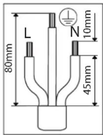
text_image
80mm L N 10mm 45mmIMPORTANT: Follow these cut back cable guidelines, to ensure the product has a reliable electrical connection.
IMPORTANT: The unused supply terminal block must not be used for any other purpose.
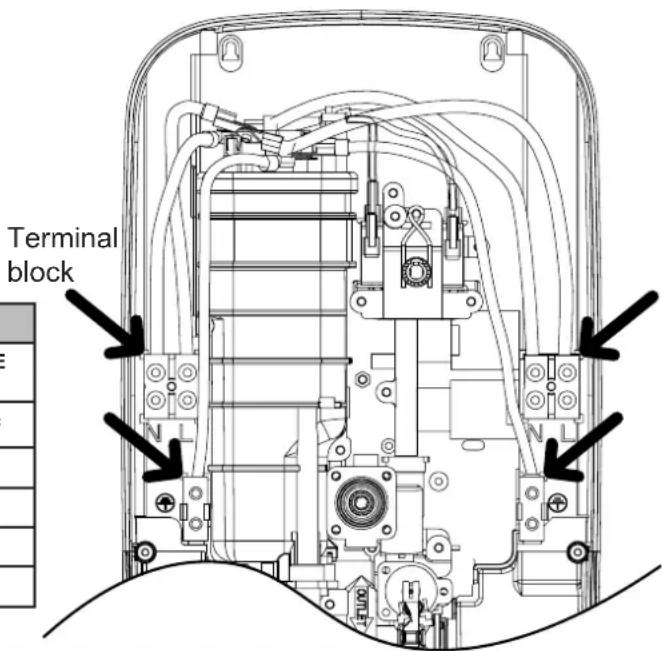
text_image
Terminal block
IMPORTANT

Ensure that the terminal block screws are fully tightened and that no cable insulation is trapped under screws, and tighten periodically in accordance with BS 7671. The earth continuity conductor of the electrical installation must be effectively connected to all exposed metal parts of other appliances and services in the room in which the shower unit is installed to conform with BS 7671.
The unused supply terminal block must not be used for any other purpose.
Electrical Connections Cont..
IMPORTANT: The use of connections within the unit or other points in the shower circuit to supply power to other equipment such as an extractor fan or pump etc will invalidate the guarantee.
The diagram below shows a schematic wiring diagram.
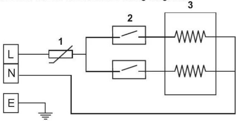
text_image
L N E 1 2 3-
Thermal Cut-Out
-
Pressure Switch
-
Heater Body
10. Fitting the Front Cover
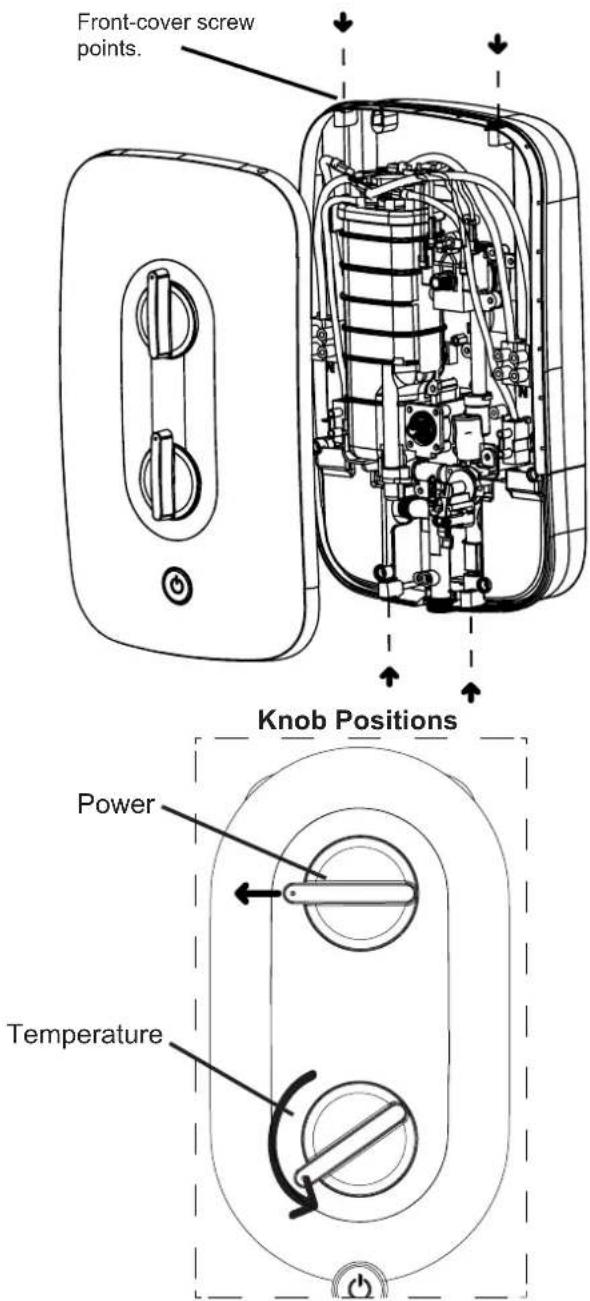
IMPORTANT: It is necessary to align the control knobs on the cover with the opposite control spindles mounted on the back plate before the front cover is fitted. The sealing cord should be located in groove.
-
First turn the power selector knob; identified by the solid blue line, to the cold position.
-
Then turn the temperature control knob anti-clockwise to the mechanical stop position (minimum temperature).
-
On the shower back plate make sure that the power selector spindle key way is pointing LEFT and the temperature spline spindle is rotated fully anti-clockwise until it reaches the mechanical stop.
-
Remove instruction card from spindle. The front cover can now be fitted carefully ensuring the controls are aligned and secured with the four fixing screws provided.
-
Following the installation of the riser rail (see section 11) attach the flexible hose to the shower outlet positioned centrally on the back plate making sure that you use the sealing washer provided. The shower is now ready for commissioning.
text_image
Front-cover screw points. Knob Positions Power Temperature11. Riser Rail Fitting Instructions
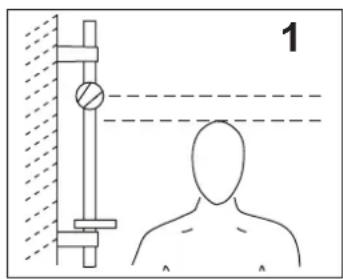
- Establish position for the riser rail, and mark the wall for the lower mounting bracket. Make allowances for the tallest person likely to use the shower regularly.
- Remove covers from the wall brackets.
- Position the top bracket and mark the wall for the screw fixing. Drill, plug the wall and fix the top bracket.
- Fit the rail into the top bracket. Place the remaining bracket onto the rail. Ensure the rail is vertically aligned and mark the wall. Remove the rail and bracket, then drill and plug the wall.
- Slide the height adjuster onto the rail, release mechanism with push button. Then fit the soap dish, dampening the rail will make it easier to slide on.
- Replace the rail assembly into the top bracket. Refit the bottom bracket, ensuring the larger rail hole is facing outwards and fix to the wall.
- Snap covers over both brackets.
- Firmly attach shorter conical end of the flexible hose to shower handset making sure sealing washer is in place after first passing through the hose retaining ring with no kinks.
NOTE: The adjustable height adjuster grips the conical ends of the hose, not the handle of the shower handset.
text_image
1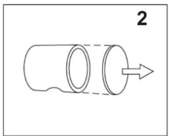
natural_image
Simple line drawing of a cylindrical object with an arrow indicating direction (no text or symbols)
natural_image
Simple line drawing of a cylindrical object with a pointed tip and dashed centerline, labeled with number 3 (no text or symbols on the object itself)
natural_image
Technical line drawing of a mechanical assembly with a cylindrical component and a tool, labeled with number 4 (no text or symbols on the diagram itself)
natural_image
Technical line drawing of a mechanical assembly with a cylindrical component and a downward arrow indicating motion (no text or symbols)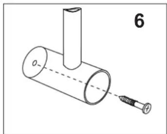
natural_image
Diagram of a mechanical assembly with a cylindrical component and a screw, labeled with number 6 (no text or symbols on the diagram itself)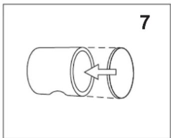
natural_image
Simple line drawing of a cylindrical object with a dashed side and an arrow indicating direction (no text or symbols)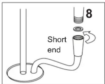
text_image
Short end 8TIPS
- A piece of insulating or masking tape applied to the wall before marking out the fixing holes will help stop the drill from wandering, particularly on tiled surfaces.
- When working near a basin or bath, insert the plug in the waste fitting so that small parts cannot be lost.
• Take care not to drop accessories or tools into basin or bath.

CAUTION

Check there are no hidden cables or pipes before drilling holes for wall plugs.
Exercise great care when using power tools near water.
The use of a residual current device (RCD) is recommended.
12. Commissioning The Shower
IMPORTANT: Make sure that the electricity supply has been disconnected at the isolation switch.
- Turn the top rotary power selector knob; identified by the solid blue line, to the Cold setting.
- Turn the rotary temperature control fully anti-clockwise to the minimum temperature position (direction of blue graphic).
- Ensure that the water supply is fully on at the mains stop cock and isolating service valve.
- Check that water is not leaking from the bottom of the case.
- Push the start / stop button and check that water flows freely from the shower within a few seconds. At this point the water from the shower handset will be at full force and at a cool temperature.
- Slowly rotate the bottom temperature control knob to the maximum temperature position (fully clockwise). This will gradually reduce the flow of water through the shower. The water temperature will remain cool.
- Return the temperature knob to the minimum temperature position (fully anticlockwise).
- Switch on the electrical supply isolation switch.
- Now turn the top power selector knob to the Eco 1 power setting indicated by the dashed red line. Allow a few seconds for the warmer temperature to reach the shower head. This shows that the Eco 1 power setting is working correctly.
-
Now turn the top power selector to the high power setting indicated by the solid red line. The temperature should rise further. This shows that the full power setting is working correctly.
-
Now adjust the bottom rotary temperature control knob clockwise for hotter water allowing a few seconds for the temperature to stabilize. Set the control to a comfortable showering temperature slowly.
- Push the start / stop button to switch the unit off.
- Switch off at the electrical isolation switch.
- Finally we recommend that the shower head is removed to make sure no debris has worked into it. Clean and re-fit.
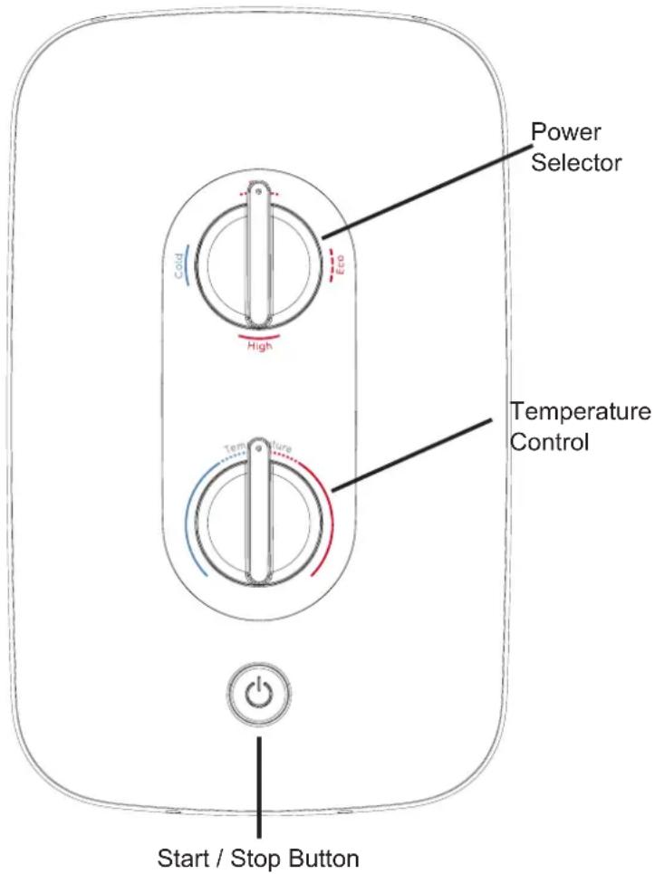
text_image
Power Selector Cold High Temperature Control Start / Stop ButtonIMPORTANT
Turn the temperature control knob anti-clockwise for maximum flow before switching on the unit. This will ensure a fast fill up of the unit when the shower is first switched on.
CAUTION
The shower unit must be full of water before heat settings are used.
13. Troubleshooting Checklist For The Installer
IMPORTANT: The following check list is provided for the benefit of the qualified installer.
WARNING: SWITCH OFF THE ELECTRICAL ISOLATION SWITCH BEFORE REMOVING THE FRONT COVER TO MAKE CHECKS.
Q. Water too cold.
A. Check the circuit through the thermal cut out.
Check circuit through the two sheathed heating elements.
NOTE: Test to be done using a low voltage resistance meter whilst the power is switched OFF at the isolating switch.
Check working voltage.
Ensure you have completed cimmissioning process and refer to installation checklist (section 2).
Q. Poor or no control over water flow.
A. Replace the water flow valve head works.
Q. No water when start / stop button is pressed.
A. Check the water supply isolating valves are fully open.
Check the mechanical solenoid is latching.
Q. Pressure relief valve operated.
A. Check for cause of high pressure such as blocked shower hose or shower handset. Replace pressure relief valve disc. (Note: this is not covered under the product guarantee.)
Customer Service Department
Tel: 0344 879 3588*
Email: Customer.services@glendimplex.com
8.30am - 5pm, Monday - Friday
*Calls charged at low call rate plus your telephone company's network access charge.
1. Important Safety Information
Products manufactured by Redring Xpelair Group are safe and without risk provided they are installed, used and maintained in good working order in accordance with our instructions and recommendations.
FOR THE USER:
⚠️ DO NOT operate the unit if the handset or shower hose becomes damaged.
⚠️ DO NOT restrict flow out of shower by placing shower handset in direct contact with your body or other object.
WARNING: the outlet of the shower acts as a vent and must not be connected to anything other than the flexible shower hose and handset supplied or approved by the manufacturer.
⚠️ DO NOT operate the shower if water ceases to flow during use or if water has entered inside the unit because of an incorrectly fitted cover.
⚠️ DO NOT place items such as soap, shampoo or other such bottles on top of the unit as liquid could leak through the joint between the cover and back plate and damage the sealing rubber.
The shower spray head MUST be cleaned regularly to remove scale and debris. The frequency of the cleaning will vary according to the local water quality. If the water outlet temperature becomes hot and you are unable to obtain cooler water, immediately check the shower handset for blockage. See section 4 for cleaning instructions.
In order to avoid damage to your shower, the electrical isolation switch must be turned off between uses.
⚠️ Under no circumstances must any shower head that is not approved by the manufacturer be used with this product. Fit only shower heads recommended by the manufacturer and never fit any additional device to restrict the water outlet flow.
The outlet must not be connected to any tap or fitting other than those specified.
2. Operating The Shower
- Switch on the electrical supply at the isolation switch.
NOTE: We recommend that you do not stand under the spray from the shower handset when switching on – wait until the water has reached a stable warm temperature. - Push the start / stop button for immediate water flow.
- Select your power setting using the top rotary control. There are four power settings:

HIGH - Indicated by a solid red line

ECO 1 - Indicated by a dashed red line

ECO 2 - Indicated by a dotted red line

COLD - Indicated by a solid blue line
NOTE: Eco 1 and Eco 2 settings
These are the low power settings for increased economy in the warmer months or when a cooler shower is preferred. Fine tune outlet temperature adjustment is via the bottom rotary temperature control.
NOTE: High setting
This is the full power setting. Fine tune outlet temperature adjustment is via the bottom rotary temperature control.
NOTE: If cold setting is selected the heating elements are not energised so the water temperature will be at the incoming water mains ambient which will be warmer in summer and colder in the winter months.
Adjustment of the rotary temperature control on this setting will only alter the flow of water not the water temperature.
IMPORTANT: When making a temperature adjustment the unit can take up to 20–30 seconds to stabilize at the new temperature. Please wait before making further adjustments.
- The temperature control knob alters the outlet temperature by increasing or reducing the flow rate of water through the shower unit.
- To increase the temperature turn the control knob clockwise (in the direction of the red graphic) and this will decrease the flow. To reduce the temperature turn the control knob anti-clockwise (in the direction of the blue graphic) and this will increase the flow.
- To turn off the shower unit push the start / stop button.
NOTE: A small amount of water will be retained in the shower head after the shower has been turned off. This may drain over a few minutes.
- Finally switch off electricity supply at the isolation switch.
IMPORTANT: Once the power and temperature controls are set the shower can be switched on and off by the separate start / stop push button. Only occasional adjustment of the rotary flow / temperature control will be necessary for winter / summer changes in the incoming cold water ambient temperatures.
Adjusting the 3 mode shower handset
The supplied shower handset has three spray patterns. These modes are selected by rotating the spray plate clockwise or anticlockwise until the desired mode is selected, when rotating the spray plate you will hear an audible click indicating when the required mode is properly engaged.
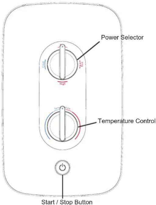
text_image
Power Selector High Temperature Control Start / Stop Button3. How Your Shower Works
- The cold incoming water is heated instantaneously as it flows over the heating elements in the heat exchanger assembly.
- At the start up the shower will reach temperature in 20–30 seconds.
- The amount of hot water available at the set temperature is limited by the total power of the heater.
- The water is turned on and off by the solenoid valve built into the shower.
- A stabilizer built into the water flow valve automatically compensates for small fluctuations in water pressure that frequently occur in households.
4. Routine Maintenance
SHOWER HANDSET CLEANING INSTRUCTIONS
The shower handset should be cleaned periodically to remove lime scale or debris which will reduce the performance of the shower. The frequency of the cleaning will vary according to local water quality.
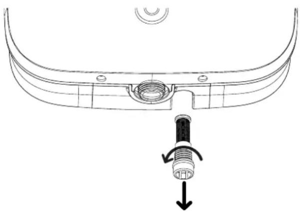
FILTER CLEANING INSTRUCTIONS
It is recommended that the filter is periodically cleaned in order to maintain the performance of the shower. It is essential that this operation is carried out by a competent person.
IMPORTANT: Before servicing, switch off the electricity supply at the isolation switch.
- Switch off the mains water supply at the isolation valve.
- The inlet filter is situated inside the water inlet housing.
- To gain access unscrew the filter cap from the bottom of the inlet housing.
- Inspect o-ring for damage when the filter cap is removed.
- To reassemble, follow procedure in reverse.
-
DO NOT over tighten the filter cap on reassembly.
-
A thermal cut-out is mounted on top of the heat exchanger.
Stage 1 switches the power off to the elements if it senses an excessive temperature. The switch operates with an audible click and will re-set if cold water is run through the shower.
Stage 2 only operates if an extreme temperature is sensed. The cut-out will permanently switch off and will then have to be replaced.
- A pressure relief device is fitted to the bottom of the heat exchanger body to safeguard against a build up of pressure in the heater. It provides protection to the heater should there be an excessive build up of pressure occur. If this device operates then a replacement part will be required.

natural_image
Diagram of a container with a submerged object and bubbles, no text or symbols presentPlace shower handset in de-scale soultion.
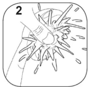
natural_image
Illustration of a biological structure with spiky protrusions and a central body, no text or symbols presentRinse shower handset with water.
natural_image
Technical line drawing of a mechanical component with a threaded fitting and directional arrow (no text or symbols)
ATTENTION!

Do not operate the shower unit if the shower head or hose becomes damaged. The shower is designed and approved to EN-60335 with the shower head provided. Under no circumstances must any shower head that is not approved by the manufacturer be used with this product also never fit any additional device to restrict the water flow.
5. Troubleshooting and Frequently Asked Questions
IMPORTANT: If an answer requires removal of front cover, please seek help of qualified person.
- If the performance of your shower deteriorates in service please follow the self help items detailed below before seeking professional advice from the installer.
- If the actions below fail to restore the shower performance you should initially contact the person or company that installed the shower.
Q. Water does not flow when start/stop button is pressed.
A. Three things to check:
- Check the mains water supply is fully open at the isolation valve.
- Check that the mains water supply is turned on at the isolation valve.
- Check that the front cover is correctly mounted on the back plate and all cover screws are fitted correctly.
Q. Water too HOT.
A. Six possible reasons:
1. Reduce the temperature by adjusting the rotary temperature control.
2. Clean the shower handset of any dirt or debris.
3. Check that the mains water isolation valve is fully open.
4. Check that the local isolating valve is fully open.
5. Select a lower power setting.
6. Clean inlet filter of any dirt or debris.
Q. Water is dripping from the bottom of the shower.
A. Safety pressure relief may have operated. This will need to be replaced. Please contact the Glen Dimpex Customer Service.
Check the inlet mains water connection.
If the pressure relief valve has operated check the hose and handset are NOT partially or fully blocked. These would need to be replaced. Please contact Glen Dimplex Customer Service.
Q. The shower cycles from hot to cold.
A. The shower temperature is set too hot causing the thermal cut-out (safety device) to operate.
Turn temperature control knob anti-clockwise to increase water flow. Then slowly increase the water temperature by turning temperature control knob clockwise until a comfortable showering temperature has been reached.
You MUST WAIT approximately 20-30 seconds for each adjustment to affect the water temperature.
'ECO' setting may need to be selected.
Q. Water too COLD.
A. Eight things to check:
- Check the mains circuit breaker and/or fuse.
- Check that the electrical isolation switch is turned on
- Check the rotary power selector is set to high power (indicated by one solid red line).
- Increase the water temperature by adjusting the rotary temperature control in the direction of the red graphic.
- Confirm that there is sufficient mains water pressure.
- Restart the shower on the high power setting.
- Allow cold water to run through the shower to re-set the cyclic over temperature cut-out.
- If there is still no hot water, contact Glen Dimplex Customer Service.
Q. Spray pattern from the handset is poor.
A. Clean the spray plate. If the handset is adjustable select a different mode by rotating the spray plate.
Q. The shower filter and/or the handset keeps blocking or filling up with solid material.
A. Following the initial installation no solid materials should remain in your cold water supply or the electric shower unit. There is a problem with your water supply. Contact a plumber for advice.
Q. The shower hose or shower hand set become damaged or is leaking.
A. Contact Glen Dimplex Customer Service and they will advise of a suitable replacement.
Q. My electric shower is out of the warranty period and is no longer working.
A. Please contact Glen Dimplex Customer Service for advice.
UK Only:
Dimplex products deliver reliable service for normal, household use in domestic settings. All Dimplex products are individually tested before leaving the factory.
If you are a consumer and you experience a problem with your Dimplex product, which is found to be defective due to faulty materials and workmanship within the warranty period, This Dimplex warranty will cover repair or at the discretion of Dimplex replacement with a functionally equivalent Dimplex Product.
The Dimplex warranty period is Two calendar years from the date of purchase of your Dimplex product, or the date of delivery of the product, if later. The Dimplex warranty is conditional upon you providing the original purchase receipt proof of purchase. Please therefore retain your receipt as proof of purchase.
If you do experience a problem with your Dimplex product please call the helpline on +44 (0)344 879 3588 or at the address on page 20. We will need details of your Dimplex product, and a description of the fault which has occurred. Once we receive your information and proof of purchase we will contact you to make the necessary arrangements.
Dimplex product, and a description of the fault which has occurred. Once we receive your information and proof of purchase we will contact you to make the necessary arrangements.
Customers outside UK - See International on page 20.
If your Dimplex product is not covered by this Dimplex warranty there may be a charge to repair your product. However, we will contact you for an agreement to any charges before any chargeable service is carried out.
What is not covered by a Dimplex warranty?
The Dimplex warranty does not cover any of the following:
Any fault or damage to your Dimplex product due to faulty materials or workmanship occurring outside the two year warranty Period.
Any fault or damage occurring to any pre-owned Dimplex product or to any other equipment or property.
Accidental damage to your Dimplex product or damage to your Dimplex product from external sources (for example, transit, weather, electrical outages or power surges).
Fault or damage to your Dimplex product which is:
Not due to faulty materials or workmanship or which is due to circumstances outside Dimplex's control.
Caused by use of your Dimplex product for anything other than normal domestic household purposes in the country where it was purchased.
Caused by any misuse of the Dimplex product, including but not limited to any failure to use it in accordance with the Operating Instructions supplied with the product.
Caused by any failure to assemble, install, clean and maintain your Dimplex product in accordance with the Operating Instructions supplied with the product unless this was carried out by Dimplex or its authorised dealers.
Caused by repairs or altercations to your Dimplex product not carried out by Dimplex service personnel or its authorised dealer(s).
Caused by use of any consumables or spare parts for your Dimplex product which are not Dimplex specified.
Terms and Conditions
The Dimplex warranty is valid for Dimplex from the date of purchase of your Dimplex product from a recognised retailer in the country of purchase
and use, or the date of the product if later, always provided the original receipt has been retained and is produced as proof of purchase.
You must provide to Dimplex or its authorised agents on request the original receipt as proof of purchase and - if required by Dimplex - proof of delivery. If you are unable to provide this documentation, you will be required to pay for any repair work required.
Any repair work under the Dimplex warranty will be carried out by Dimplex or its authorised dealer(s) and any parts that are replaced will become the property of Dimplex. Any repairs performed under the Dimplex warranty will not extend the warranty period.
Any replacement of your Dimplex product by Dimlex during the warranty period will start the Two year warranty period afresh from the date of delivery of the replacement Dimplex product to you.
The Dimplex warranty does not entitle you to recover of any indirect or consequential loss or damage including but not limited to loss or damage to any other property.
The Dimplex warranty is in addition to your statutory rights as a consumer and your statutory rights are not affected by this Dimplex warranty.
7. Energy Related Product Directive (ErP)
This information shows how our products pass the relevant European Union Energy Directives (ErP).
| Supplier's / Manufacturer | DIMPLEX | |||
| Supplier's Model Identifier | VERVE | |||
| Supplier's Model Number DVES85 DVES95 | ||||
| Declared Load Profile XS | ### | |||
| Energy Efficiency Class A A | ||||
| Energy Efficiency % 39 39 | ||||
| Annual Engery Consumption (KWh / annum) 478 | 479 | |||
| Other Load Profiles No | ||||
| Thermostat Temperature Setting (°C) Not Applicable | ||||
| Sound Power Level, Indoors (dB) 15 15 | ||||
| Off Peak Function No | ||||
| Specific precautions that shall be taken when the heater is assembled, installed or maintained | Follow all product installation, care and maintenance instructions as listed in the main 'Instruction/Installation Manual' | |||
| Smart No | ||||
Contact Dimplex
If you have any questions about what the Dimplex warranty covers and does not cover or how to claim under Dimplex warranty, please contact us using the information below.
Contact details:
Millbrook House, Grange Drive, Hedge End, Southampton, SO30 2DF
Telephone: +44 (0) 344 879 3588
Email: Customer.services@glendimplex.com
http://www.glendimplex.com
International
Warranty: Contact your local distributor or Dimplex direct for details.
Technical advice and service: Contact your local Dimplex distributor.
© Glen Dimplex. All rights reserved. Material contained in this publication may not be reproduced in whole or in part, without prior permission in writing of Glen Dimplex
For electrical products sold within the European Community. At the end of the electrical products useful life it should not be disposed of with household waste. Please recycle where facilities exist. Check with a Local Authority or retailer for recycling advise in your country. Batteries should be disposed of or recycled in accordance with WEEE Directive 2012/EU. Packaging should be recycled where possible.
Millbrook House, Grange Drive,
Hedge End, Southampton, SO30 2DF
Tel: +44 (0) 344 879 3588
Customer Service Email: Customer.services@glendimplex.com
Calls charged at low call rate plus your telephone company's network access charge.