TBS-254 - Saw Ozito - Free user manual and instructions
Find the device manual for free TBS-254 Ozito in PDF.


| Product Type | Bench Saw |
| Model | Ozito TBS-254 |
| Power Supply | 240V / 50Hz |
| Power Rating | 1500W |
| Blade Diameter | 254mm (10 inch) |
| Blade Bore | 30mm |
| No Load Speed | 4500 rpm |
| Max Depth of Cut at 90° | 80mm |
| Max Depth of Cut at 45° | 55mm |
| Table Size | 600 x 500mm |
| Rip Capacity | 600mm |
| Weight | 22 kg |
| Dimensions (L x W x H) | 700 x 550 x 450 mm |
| Main Functions | Rip cuts, crosscuts, mitre cuts, bevel cuts |
| Safety Features | Blade guard, riving knife, push stick, emergency stop |
| Dust Extraction | 36mm dust port |
| Table Extension | Sliding table or side extensions (optional) |
| Maintenance | Clean sawdust regularly; check blade sharpness; lubricate moving parts |
| Spare Parts Availability | Replacement blades, belts, and guards available through Ozito service centers |
| Repairability | Moderate; user-replaceable components like blade and belt |
| Warranty | 2 years domestic use |
| Certifications | CE, RoHS |
Frequently Asked Questions - TBS-254 Ozito
User questions about TBS-254 Ozito
0 question about this device. Answer the ones you know or ask your own.
Ask a new question about this device
Download the instructions for your Saw in PDF format for free! Find your manual TBS-254 - Ozito and take your electronic device back in hand. On this page are published all the documents necessary for the use of your device. TBS-254 by Ozito.
USER MANUAL TBS-254 Ozito
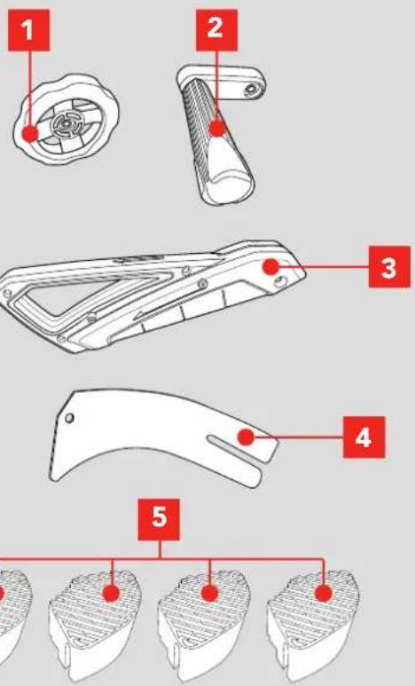
1 Bevel Adjustment Dial
4 Riving Knife
2 Height Adjustment Handle
5 Rubber Feet x 4
3 Blade guard
FASTENERS
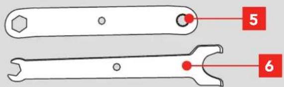
5 Spanner 10mm/Pin 6 Spanner 10/12mm
ONLINE MANUAL
Scan this QR Code with your mobile device to take you to the online manual.

ASSEMBLING THE DIAL

WARNING BEFORE ASSEMBLING YOUR TABLE SAW OR REPLACING BLADES, MAKE SURE THAT THE MOTOR IS OFF AND THE TOOL IS DISCONNECTED FROM THE POWER SUPPLY TO PREVENT ACCIDENTAL STARTING.
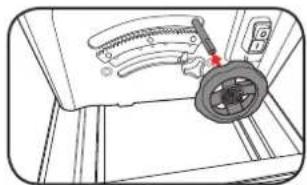
2 Remove the screw from the height / bevel rod and slide the bevel adjustment dial onto the rod ensuring the teeth on cogs align.
natural_image
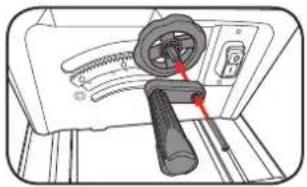
Technical line drawing of a mechanical assembly with a gear and curved components (no text or symbols)3 Slide the height adjustment handle onto the rod by aligning the flat section and secure in place using the screw that was previously removed.
natural_image
Diagram of a hand tool interacting with a device panel, showing a handle and control knob (no text or symbols)4 Ensure the blade height is wound fully down and then turn the table saw upside down on the floor.
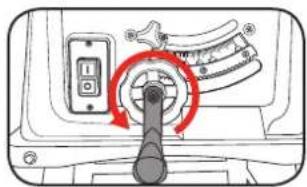
5 Remove any cardboard boxes from behind the motor; it can be easily accessed by tilting the blade using the Blade Bevel Adjustment.
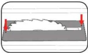
1 Flip the table saw upright onto it's feet, raise the blade to it's highest setting and remove the table insert by loosening the 2 screws holding it down.
natural_image
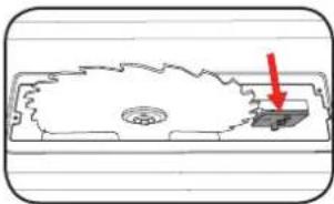
Diagram showing a curved object on a flat surface with two red arrows pointing to it, no text or symbols present.2 Loosen the riving knife securing bolt using the supplied spanner, ensuring the bolt does not come completely out as this bolt may be difficult to refit.
natural_image
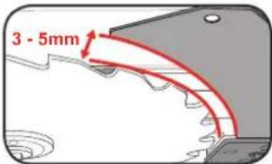
Simple line drawing of a mechanical component with a red arrow pointing to a specific part (no text or symbols)3 Insert the riving knife between the mounting plate and the securing bolt so that there is a 3-5mm gap between the blade and the riving knife. Tighten the securing bolt using the supplied spanner.
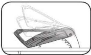
4 Mount the blade guard to the top of the riving knife using it's nut and bolt. Do not tighten the bolt too far – the blade guard must be able to move freely.
natural_image
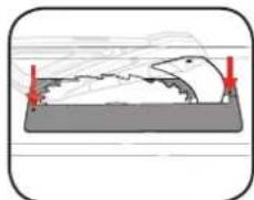
Illustration of a mechanical component or bracket with layered structure (no text or symbols)5 Fit the table insert and secure with it's 2 screws.
natural_image
Diagram of a fish-shaped object on a rectangular base with red arrows indicating points of interest (no text or symbols)IMPORTANT! THE BLADE GUARD MUST ALWAYS BE LOWERED OVER THE WORK PIECE BEFORE YOU BEGIN TO CUT.
NG THE RUBBER FEET
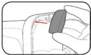
1 Turn the table saw on its side and press one of the supplied rubber feet securely onto the corner of the frame..
natural_image
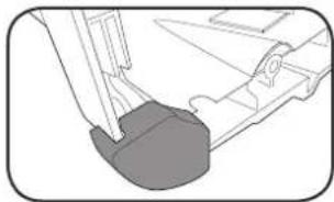
Illustration of a hand holding a small object with a red arrow pointing to it, no text or symbols present.2 Repeat the process for the other three rubber feet.
natural_image
Mechanical component diagram showing a lever and base assembly (no text or symbols)ozito TABLE SAW
2000W 254mm
INSTRUCTION MANUAL
SPECIFICATIONS
Motor: 2000W (S6 40%) 1800W (S1)
Input: 230-240V \~ 50Hz
No Load Speed: 4,250/min
Blade: ∅254mm x ∅30 x 2.8mm
Blade Teeth: 24 TCT
Bevel Angle: 0°-45° left
Blade Height Adj: 0-80mm
Max. Cutting Capacity:
Bevel 90°: 80mm
Bevel 45°: 53mm
Table Size: 638 x 430mm
Dust Port: ∅36mm
Weight: 19.5kg
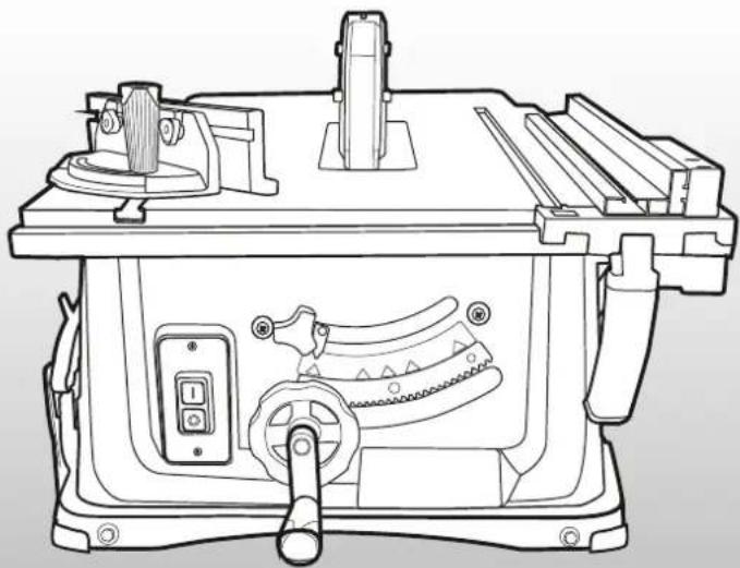
natural_image
Technical line drawing of a machine tool with no visible text or symbolsWHAT'S IN THE BOX
Table Saw
Sliding Mitre Gauge, Rip Fence
Cutting Blade, Push Stick & Rubber Feet
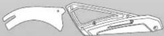
Blade Guard & Riving Knife
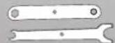
2 x Spanners
ozito.com.au
3
YEAR REPLACEMENT WARRANTY
TBS-254
WARRANTY
IN ORDER TO MAKE A CLAIM UNDER THIS WARRANTY YOU MUST RETURN THE PRODUCT TO YOUR NEAREST BUNNINGS WAREHOUSE WITH YOUR BUNNINGS REGISTER RECEIPT. PRIOR TO RETURNING YOUR PRODUCT FOR WARRANTY PLEASE TELEPHONE OUR CUSTOMER SERVICE HELPLINE:
Australia 1800 069 486
New Zealand 0508 069 486
TO ENSURE A SPEEDY RESPONSE PLEASE HAVE THE MODEL NUMBER AND DATE OF PURCHASE AVAILABLE. A CUSTOMER SERVICE REPRESENTATIVE WILL TAKE YOUR CALL AND ANSWER ANY QUESTIONS YOU MAY HAVE RELATING TO THE WARRANTY POLICY OR PROCEDURE.
The benefits provided under this warranty are in addition to other rights and remedies which are available to you at law.
Our goods come with guarantees that cannot be excluded at law. You are entitled to a replacement or refund for a major failure and for compensation for any other reasonably foreseeable loss or damage. You are also entitled to have the goods repaired or replaced if the goods fail to be of acceptable quality and the failure does not amount to a major failure.
Generally you will be responsible for all costs associated with a claim under this warranty, however, where you have suffered any additional direct loss as a result of a defective product you may be able to claim such expenses by contacting our customer service helpline above.
3 YEAR REPLACEMENT WARRANTY
Your product is guaranteed for a period of 36 months from the original date of purchase. If a product is defective it will be replaced in accordance with the terms of this warranty. Warranty excludes consumable parts, for example: blade, push stick, spanners, bearings & carbon brushes.
WARNING
The following actions will result in the warranty being void.
- If the tool has been operated on a supply voltage other than that specified on the tool.
- If the tool shows signs of damage or defects caused by or resulting from abuse, accidents or alterations.
- Failure to perform maintenance as set out within the instruction manual.
- If the tool is disassembled or tampered with in any way.
• Professional, industrial or high frequency use.
KNOW YOUR PRODUCT
TABLE SAW
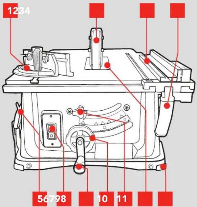
1 Sliding Mitre Gauge 7 Blade Height Adjustment Handle
2 Blade Guard 8 Bevel Adjustment Dial
3 Rip Fence 9 Bevel Lock
4 Rip Fence Lever 10 Table Insert
5 Push Stick 11 Rubber Feet
6 ON/OFF Switch
ONLINE MANUAL
Scan this QR Code with your mobile device to take you to the online manual.

SETUP & PREPARATION
1. ADJUSTMENTS
For detailed assembly instructions see Assembly Manual.

WARNING! ENSURE THE TOOL IS SWITCHED OFF AND DISCONNECTED FROM THE POWER SUPPLY BEFORE PERFORMING ANY OF THE FOLLOWING PROCEDURES.
Cutting Depth
The depth should be adjusted so that no more than one tooth is protruding through the timber. This helps to minimise splintering.
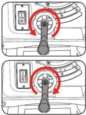
1 To lower the blade for a smaller depth of cut, rotate the blade height adjustment handle anticlockwise.
2 To raise the blade for a larger depth of cut, rotate the blade height adjustment handle clockwise.

WARNING! THIS TOOL IS NOT INTENDED FOR CHANNEL OR TRENCH CUTS.
Bevel Angle
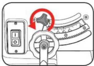
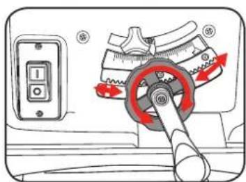
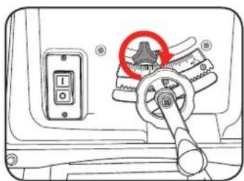
1 Loosen the bevel lock by rotating anti-clockwise.
2 Rotate the bevel adjustment dial in to the desired angle using the bevel scale.
3 Secure the bevel angle by rotating the bevel lock clockwise.
2. SETTING THE RIP FENCE
Rip Fence Stop Height
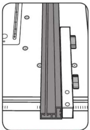
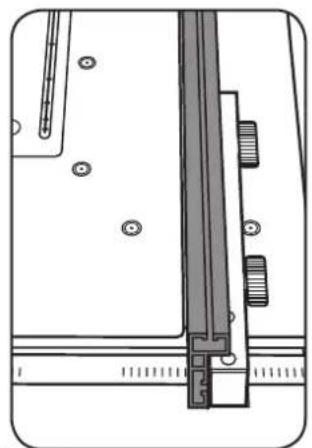
The rip fence supplied with the table saw has two different guide faces. 1 for thick material and 1 for thin material.
natural_image
Technical diagram of a mechanical assembly with no visible text or symbolsThin Material Thick Material
natural_image
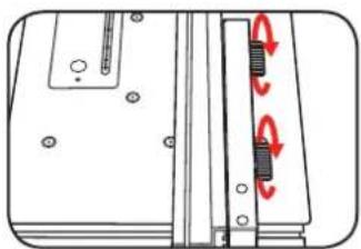
Technical line drawing of a mechanical assembly with no visible text or symbols1 To change the stop rail, loosen the 2 screws.
natural_image
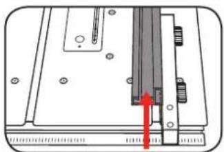
Diagram of a mechanical assembly with red arrows indicating rotational motion (no text or symbols)2 Slide the stop rail off and re-insert into the desired rail.
Note: The screws can also be removed and re-inserted from the other direction so that the flat guide face is on the opposite side.
natural_image
Technical diagram of a mechanical assembly with a red arrow pointing to a component (no text or symbols present)3 Tighten the 2 screws to lock in place.
Rip Fence Cutting Width
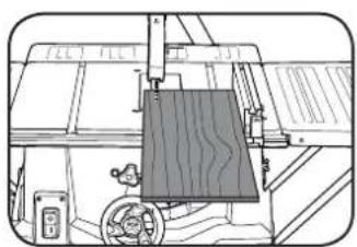
The rip fence has to be used when making longitudinal cuts in wooden work pieces.
The rip fence can be mounted on either side of the saw table but may require you to change the orientation of the guide rail.
natural_image
Technical line drawing of a mechanical assembly with no visible text or symbols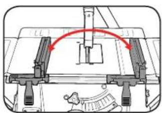
natural_image
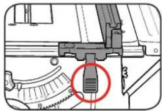
Mechanical assembly diagram showing a bracket with red arrows indicating motion or direction (no text or symbols)1 Loosen the rip fence lever and insert the fence onto the table guide rail.
natural_image
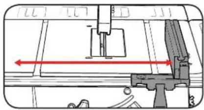
Mechanical component diagram showing a lever and adjustment knob with a red circle highlighting a specific feature (no text or symbols present)2 Slide the rip fence to the desired dimension using the scale on the guide rail.
natural_image
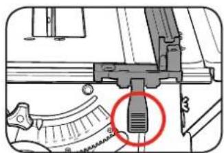
Technical diagram of a mechanical assembly with no visible text or symbols3 Tighten the rip fence lever to lock the rip fence in position.
Setting the Stop Length
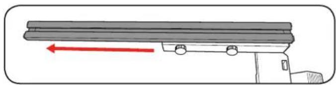
The stop rail can be moved in a longitudinal direction in order to prevent the workpiece from becoming jammed.
natural_image
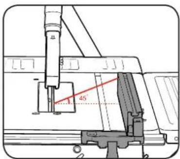
Diagram of a mechanical lever system with a red directional arrow indicating motion (no text or symbols present)Note: As a rule of thumb, the rear end of the stop comes up against an imaginary line that begins roughly at the centre of the blade and runs at an angle of 45^ to the rear.
1 Set the required cutting width.
2 Loosen the 2 fence screws and push the stop rail forward until it touches the imaginary 45° line.
3 Retighten the 2 fence screws.
OPERATION
3. SETTING THE MITRE GAUGE
Using the Sliding Mitre Gauge
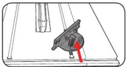
The sliding mitre gauge can be fitted into 1 of the 2 grooves in the table and can be used to easily perform mitre angle cuts.
1 Slide the rail of the mitre gauge into 1 of the grooves of the table.
natural_image
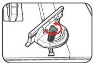
Mechanical assembly diagram showing a component inserted into a housing with a red arrow indicating direction (no text or symbols present)2 Loosen the screw to adjust the mitre angle.
natural_image
Mechanical device diagram showing a rotating component with a red circular arrow indicating rotation (no text or symbols)3 Rotate the mitre gauge to the desired angle using the mitre scale.
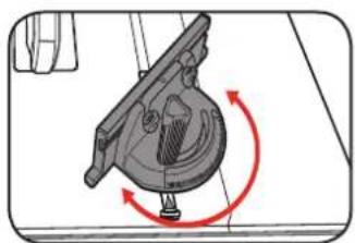
natural_image
Mechanical component diagram showing rotational motion with red arrows indicating rotation (no text or symbols)4 Lock the mitre angle by tightening the screw.
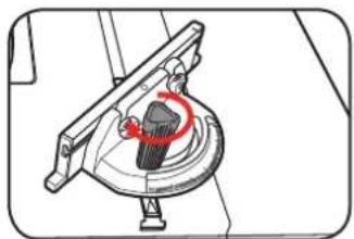
natural_image
Mechanical assembly diagram showing a rotating component with a red circular feature (no text or symbols)
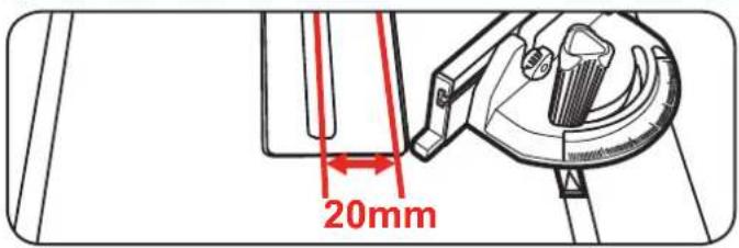
IMPORTANT! DO NOT PUSH THE MITRE GAUGE STOP RAIL TOO FAR TOWARD THE BLADE. THE DISTANCE BETWEEN THE STOP RAIL AND THE BLADE SHOULD BE APPROXIMATELY 20MM.
4. USING THE TABLE SAW

CAUTION TO REDUCE THE RISK OF ELECTRICAL SHOCK, THE USE OF A RESIDUAL CURRENT DEVICE (RATED 30mA OR LESS) IS RECOMMENDED.
On / Off Switch
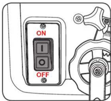
1 To turn the saw ON, press the green button "I".
Note: Wait for the blade to reach its maximum speed before commencing with the cut.
2 To turn the saw OFF, press the red button "0".
Blade Guard
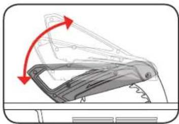
1 The blade guard must be able to move freely, adjust if necessary (refer to Assembly Manual).
natural_image
Mechanical assembly diagram showing a bracket with red arrows indicating motion direction (no text or symbols)
IMPORTANT! THE BLADE GUARD MUST ALWAYS BE LOWERED OVER THE WORK PIECE AND MOUNTED SECURELY BEFORE YOU BEGIN TO CUT.

IMPORTANT! AFTER EVERY NEW ADJUSTMENT WE RECOMMEND YOU MAKE A TRIAL CUT IN ORDER TO CHECK THE NEW SETTINGS.
5. MAKING A CUT
Making Longitudinal Cuts / Ripping
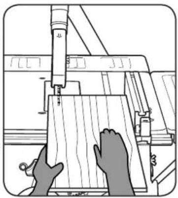
Press one edge of the workpiece against the rip fence while the flat side lies on the saw table. The blade guard must always be lowered over the workpiece.
When you make a longitudinal cut, never adopt a working position that is in line with the cutting direction.
1 Set the rip fence in accordance with the workpiece height and the desired width. (See Stop Height, Cutting Width).
2 Switch on the saw by pressing the ON button "I".
3 Place your hands (with fingers closed ensuring they will be clear of the blade) flat on the workpiece and push the workpiece along the rip fence and into the blade.
4 Guide at the side with your left or right hand (depending on the position of the rip fence) only as far as the front edge of the table.
5 Always push the workpiece through to the end of the riving knife.
6 The off cut piece remains on the saw table until the blade is back in its position of rest.
7 Secure long work pieces against falling off at the end of the cut (e.g. with a roller stand etc.).
natural_image
Illustration of hands operating a wooden cutting machine with a tool inserted (no text or symbols visible)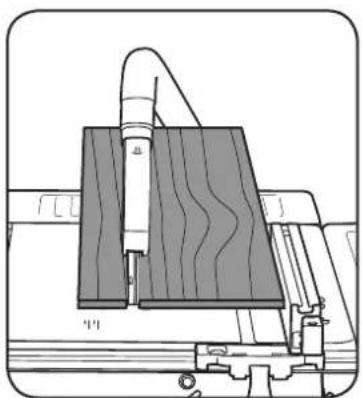
natural_image
Technical diagram of a mechanical assembly with layered components and no visible text or symbols
WARNING! KEEP HANDS WELL CLEAR OF THE BLADE AT ALL TIMES. IT IS RECOMMENDED TO USE THE PUSH STICK EVEN IF CUTTING WIDE MATERIAL.
Cutting Narrow Work Pieces

IMPORTANT! BE SURE TO USE A PUSH STICK WHEN MAKING LONGITUDINAL CUTS.
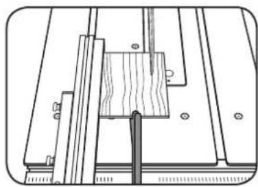
Be sure to use a push stick when making longitudinal cuts in work pieces smaller than 120mm in width. A push stick is supplied with the saw.
Replace a worn or damaged push stick immediately.
natural_image
Technical line drawing of a mechanical assembly with wooden components and mounting holes (no text or symbols)Making Bevel Cuts
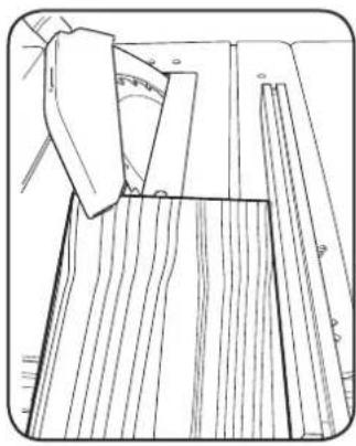
Bevel cuts must always be done using the rip fence.
1 Set the blade to the desired angle. (See Setting the Bevel Angle)
2 Set the rip fence in accordance with the workpiece width and height (see Stop Height)
3 Carry out the cut in accordance with the workpiece width.
natural_image
Line drawing of a wooden folding or folding process with folded panels and measurement markings (no text or symbols)Making Cross Cuts
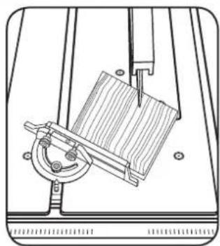
1 Slide the sliding mitre gauge into one of the grooves in the table and adjust to the required angle (see Sliding Mitre Gauge).

IMPORTANT! DO NOT PUSH THE MITRE GAUGE STOP RAIL TOO FAR TOWARD THE BLADE. THE DISTANCE BETWEEN THE STOP RAIL AND THE BLADE SHOULD BE APPROXIMATELY 20MM.
2 Press the workpiece firmly against the sliding mitre gauge.
3 Switch on the saw by pressing the ON button "I".
4 Push the sliding mitre gauge and the workpiece toward the blade in order to make the cut.
5 Push the sliding mitre gauge forward until the workpiece is cut all the way through.
6 Switch off the saw again. Do not remove the off-cut until the blade has stopped rotating.
natural_image
Technical line drawing of a mechanical device with a lever and base plate (no text or symbols)6. ADJUSTING THE RIVING KNIFE 7. BLA
Setting the Riving Knife
Note: The riving knife helps to prevent kickback and should be checked each time the blade is replaced.
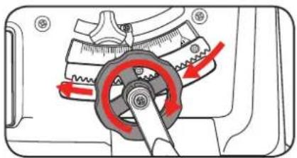
1 Set the blade to the Max cutting depth by rotating the blade height adjustment handle and setting the bevel adjustment to 0°.
natural_image
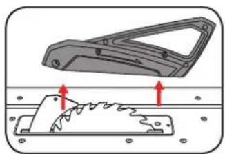
Mechanical gear assembly diagram showing a rotating wheel and adjustment mechanism (no text or labels)2 Remove the blade guard by removing the bolt.
3 Unscrew the countersunk head screw and remove the table insert.
natural_image
Mechanical component diagram showing a handle and saw cutting process (no text or symbols)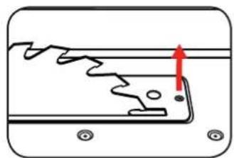
natural_image
Pure diagram of a mechanical component with no text, numbers, or symbols4 Loosen the fixing screw.
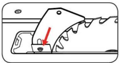
natural_image
Mechanical component diagram showing a gear-like structure with a red arrow indicating a specific feature (no text or symbols present)5 Raise the riving knife until the clearance between the blade and the riving knife is 3-5mm.
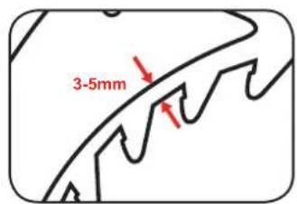
6 Retighten the fixing screw and then refit the table insert and blade guard.
DE REPLACEMENT
Fitting / Replacing the Blade
Note: This product is designed for 254mm saw blades for timber cutting only.

WARNING! ENSURE THE TOOL IS SWITCHED OFF AND DISCONNECTED FROM THE POWER SUPPLY BEFORE PERFORMING ANY OF THE FOLLOWING PROCEDURES.

WARNING! USE ONLY SAW BLADES WHERE THE RIVING KNIFE IS NOT THICKER THAN THE WIDTH OF THE GROOVE CUT BY THE SAW BLADE AND NOT THINNER THAN THE BODY OF THE SAW BLADE.

WARNING! ENSURE THAT THE SAW BLADE IS SUITABLE FOR THE MATERIAL TO BE CUT AND THAT THE MAXIMUM POSSIBLE SPEED IS NOT LESS THAN THE MAXIMUM TOOL SPEED.
1 Set the blade to the Max cutting depth by rotating the blade height adjustment and setting the bevel adjustment to 0^ .
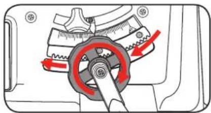
natural_image
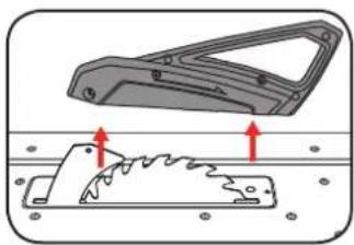
Mechanical device with gear and pulley mechanism, showing red directional arrows indicating motion (no text or symbols)2 Remove the blade guard by removing the bolt.
3 Unscrew the countersunk head screw and remove the table insert.
natural_image
Diagram showing a mechanical component with arrows indicating movement or force, no text or symbols present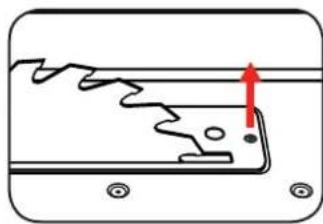
natural_image
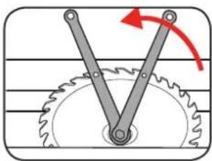
Pure diagram of a mechanical component with no text, numbers, or symbols4 Undo the blade bolt with the pin spanner and 12mm spanner on the blade outer flange to apply counter-pressure. Keep fingers and hands away from blade. Wear leather gloves
natural_image
Mechanical diagram showing a gear and shaft assembly with a red curved arrow indicating rotational motion (no text or symbols)
IMPORTANT| TURN THE BLADE BOLT IN THE DIRECTION OF ROTATION OF THE SAW BLADE.
5 Take off the outer flange and pull the old saw blade off the inner flange by dropping the blade at an angle.
DESCRIPTION OF SYMBOLS
6 Clean the blade flange thoroughly before fitting the new blade.
7 Mount and fasten the new saw blade following the previous steps reverse order. Ensure the blade direction matches the arrow direction indicated on the housing.
8 Refit and set the riving knife, table insert and the blade guard.
9 Check to make sure that all safety devices are properly mounted and in good working condition before you begin working with the saw again.

IMPORTANT! NOTE THE RUNNING DIRECTION. THE CUTTING ANGLE OF THE TEETH MUST POINT IN RUNNING DIRECTION, I.E. FORWARDS (SEE THE ARROW ON THE BLADE GUARD).
8. TABLE INSERT
Changing the table insert
1 To prevent increased likelihood of injury the table insert should be changed whenever it is worn or damaged.
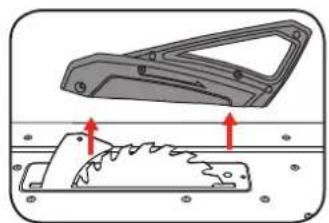
2 Remove the blade guard by loosening the bolt.
3 Remove the 2 countersunk screw.
4 Take out the worn table insert.
5 To fit the replacement table insert, proceed in reverse order.
natural_image
Mechanical component diagram showing a bracket and internal gear assembly (no text or symbols)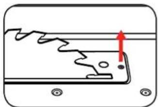
natural_image
Pure diagram of a mechanical component with no text, numbers, or symbolsADDITIONAL INFORMATION
Operating mode S6 40%: Continuous operation with idling (cycle time 10 minutes). To ensure that the motor does not become excessively hot it may only be operated for 40% of the cycle at the specified rating and must then be allowed to idle for 60% of the cycle.
| V | Volts | Hz | Hertz |
| ~ | Alternating current | W | Watts |
| /min | Revolutions orreciprocation per minute | No | No load speed |
 | ulator compliance mark | Double insulated | |
 | Warning | Danger! Keep hands awayfrom blades | |
— | Read instruction manual | Wear eye protection | |
 — — | Wear hearing protection | Wear breathing protection | |
 — — | Wear safety gloves | ||
CARING FOR THE ENVIRONMENT

Power tools that are no longer usable should not be disposed of with household waste but in an environmentally friendly way. Please recycle where facilities exist. Check with your local council authority for recycling advice.

Recycling packaging reduces the need for landfill and raw materials. Reuse of recycled material decreases pollution in the environment. Please recycle packaging where facilities exist. Check with your local council authority for recycling advice.
SPARE PARTS
254mm saw blade that fit this unit are readily available at your local Bunnings Warehouse. When purchasing a blade, ensure it can be fitted to the bore size of this tool.
Spare parts can be ordered from the Special Orders Desk at your local Bunnings Warehouse.
For further information, or any parts not listed here, visit www.ozito.com.au or contact Ozito Customer Service:
Australia 1800 069 486
New Zealand 0508 069 486
E-mail: enquires@ozito.com.au

ELECTRICAL SAFETY

WARNING! When using mains-powered stationary appliances, basic safety precautions, including the following, should always be followed to reduce risk of fire, electric shock, personal injury and material damage.
Read the whole manual carefully and make sure you know how to switch the tool off in an emergency, before operating the tool.
Save these instructions and other documents supplied with this tool for future reference.
The electric motor has been designed for 230V and 240V only. Always check that the power supply corresponds to the voltage on the rating plate.
Note: The supply of 230V and 240V on Ozito tools are interchangeable for Australia and New Zealand.

This tool is double insulated therefore no earth wire is required.
If the supply cord of this power tool is damaged, it must be replaced by a specially prepared cord available through the service organization.
Note: Double insulation does not take the place of normal safety precautions when operating this tool. The insulation system is for added protection against injury resulting from a possible electrical insulation failure within the tool.
Using an Extension Lead
Always use an approved extension lead suitable for the power input of this tool. Before use, inspect the extension lead for signs of damage, wear and ageing. Replace the extension lead if damaged or defective. When using an extension lead on a reel, always unwind the lead completely. Use of an extension lead not suitable for the power input of the tool or which is damaged or defective may result in a risk of fire and electric shock.

GENERAL POWER TOOL SAFETY WARNINGS - PERSONAL SAFETY

WARNING! Read all safety warnings and all instructions. Failure to follow the warnings and instructions may result in electric shock, fire and/or serious injury.
Save all warnings and instructions for future reference. The term "power tool" in the warnings refers to your mains-operated (corded) power tool or battery-operated (cordless) power tool.
1. Work area safety
a. Keep work area clean and well lit. Cluttered or dark areas invite accidents.
b. Do not operate power tools in explosive atmospheres, such as in the presence of flammable liquids, gases or dust. Power tools create sparks which may ignite the dust or fumes.
c. Keep children and bystanders away while operating a power tool. Distractions can cause you to lose control.
2. Electrical safety
a. Power tool plugs must match the outlet. Never modify the plug in any way.
Do not use any adapter plugs with earthed (grounded) power tools. Unmodified plugs and matching outlets will reduce risk of electric shock.
b. Avoid body contact with earthed or grounded surfaces, such as pipes, radiators, ranges and refrigerators. There is an increased risk of electric shock if your body is earthed or grounded.
c. Do not expose power tools to rain or wet conditions. Water entering a power tool will increase the risk of electric shock.
d. Do not abuse the cord. Never use the cord for carrying, pulling or unplugging the power tool. Keep cord away from heat, oil, sharp edges or moving parts. Damaged or entangled cords increase the risk of electric shock.
e. When operating a power tool outdoors, use an extension cord suitable for outdoor use. Use of a cord suitable for outdoor use reduces the risk of electric shock.
3. Personal safety
a. Stay alert, watch what you are doing and use common sense when operating a power tool. Do not use a power tool while you are tired or under the influence of drugs, alcohol or medication. A moment of inattention while operating power tools may result in serious personal injury.
b. Use personal protective equipment. Always wear eye protection. Protective equipment such as dust mask, non-skid safety shoes, hard hat, or hearing protection used for appropriate conditions will reduce personal injuries.
c. Prevent unintentional starting. Ensure the switch is in the off-position before connecting to power source and/or battery pack, picking up or carrying the tool. Carrying power tools with your finger on the switch or energising power tools that have the switch on invites accidents.
d. Remove any adjusting key or wrench before turning the power tool on.
A wrench or a key left attached to a rotating part of the power tool may result in personal injury.
e. Do not overreach. Keep proper footing and balance at all times. This enables better control of the power tool in unexpected situations.
f. Dress properly. Do not wear loose clothing or jewellery. Keep your hair, clothing and gloves away from moving parts. Loose clothes, jewellery or long hair can be caught in moving parts.
g. If devices are provided for the connection of dust extraction and collection facilities, ensure these are connected and properly used. Use of dust collection can reduce dust-related hazards.
h. Do not let familiarity gained from frequent use of tools allow you to become complacent and ignore tool safety principles. A careless action can cause severe injury within a fraction of a second.
4. Power tool use and care
a. Do not force the power tool. Use the correct power tool for your application. The correct power tool will do the job better and safer at the rate for which it was designed.
b. Do not use the power tool if the switch does not turn it on and off. Any power tool that cannot be controlled with the switch is dangerous and must be repaired.
c. Disconnect the plug from the power source and/or the battery pack from the power tool before making any adjustments, changing accessories, or storing power tools. Such preventive safety measures reduce the risk of starting the power tool accidentally.
d. Store idle power tools out of the reach of children and do not allow persons unfamiliar with the power tool or these instructions to operate the power tool. Power tools are dangerous in the hands of untrained users.
e. Maintain power tools. Check for misalignment or binding of moving parts, breakage of parts and any other condition that may affect the power tool's operation. If damaged, have the power tool repaired before use. Many accidents are caused by poorly maintained power tools.
f. Keep cutting tools sharp and clean. Properly maintained cutting tools with sharp cutting edges are less likely to bind and are easier to control.
g. Use the power tool, accessories and tool bits etc. in accordance with these instructions, taking into account the working conditions and the work to be performed. Use of the power tool for operations different from those intended could result in a hazardous situation.
h. Keep handles and grasping surfaces dry, clean and free from oil and grease. Slippery handles and grasping surfaces do not allow for safe handling and control of the tool in unexpected situations.
5. Service
a. Have your power tool serviced by a qualified repair person using only identical replacement parts. This will ensure that the safety of the power tool is maintained.

TABLE SAW SAFETY WARNINGS
This appliance is not intended for use by young or infirm persons unless supervised by a responsible person to ensure that they can use the appliance safely. Young children should be supervised to ensure that they do not play with the appliance.

WARNING! Before connecting a tool to a power source (mains switch power point receptacle, outlet, etc.) be sure that the voltage supply is the same as that specified on the nameplate of the tool. A power source with a voltage greater than that specified for the
tool can result in serious injury to the user, as well as damage to the tool. If in doubt, do not plug in the tool.
Using a power source with a voltage less than the nameplate rating is harmful to the motor.
a) This tool is designed to cut timber products only. Do not use the tool to cut any other materials.
b) Do not cut firewood with this tool. The irregular shape of firewood makes it unsafe to cut with this tool.
c) Prior to operating, connect a dust extractor to the tool. This will ensure a dust-free environment for safer operation.
d) Always use recommended size blade. Do not use smaller or larger blades.
e) Do not use dull or damaged blades. Unsharpened or improperly set blades produce narrow *kerf causing excessive friction, blade binding and kickback.
f) Never use damaged or incorrect blade washers or blade bolts. The blade bolt and washers are specifically designed for the tool for optimum performance and safety of operation.
g) Ensure the blade is properly fitted and rotates in the correct direction. Incorrectly fitted blades can cause damage to the material and tool and injury to the operator.
h) Do not use damaged blades. This can result in serious injury to the operator and damage to the tool.
i) Do not use abrasive or dado blades. This can result in serious injury to the operator and damage to the tool.
j) When the blade binds in material being cut, switch off the tool and wait for blade to come to a complete stop. Investigate and take corrective action to eliminate cause of binding.
k) Blade depth and bevel adjusting locking levers must be tight and secure before making a cut. If blade adjustment shifts while cutting, it may cause binding and kickback.
I) Do not use the tool without guards in place and operating correctly. Failure to adhere to this may cause damage to the material and tool and injury to the operator.
m) Ensure all clamps, levers and locking knobs are securely tightened prior to operation. This will result in projects being produced accurately and safely.
n) Support large panels to minimise risk of blade pinching and kickback. Large panels tend to sag under their own weight. The use of roller stands and/or extension tables is recommended.
o) Allow motor to reach full speed prior to inserting blade into timber. This will result in safe operation and clean cuts.
p) Never place any part of your body in the blade area while the power is connected. Injury will be prevented by the accidental starting of the tool.
q) Never attempt to stop the blade by wedging an object against the blade. This can result in serious injury to the operator and damage to the tool.
r) Extremely small pieces of timber should not be cut with this tool in either mode. This can result in serious injury to the operator caused by flying debris.
s) Recommendation for the use of a residual current device with a rated residual current device of 30mA or less.
t) When ripping, always use the rip fence. This improves the accuracy of cut and reduces the chance of the blade binding.
u) Always use the push stick, especially when cutting narrow pieces of timber. Do not place hands in the near vicinity of the blade while operating the tool.
v) Ensure that the riving knife is properly positioned prior to operating. This will prevent the timber from binding up and stalling the blade.
w) Do not over reach to retrieve material from behind the blade. This can result in serious injury to the operator.
x) Do not use the saw to perform rebate or groove cuts unless suitable guarding, such as tunnel guard, is fitted above the saw table.
y) Do not use the saw for slotting (stopped groove) cuts.
z) Use only transportation devices and never use the cuttings guards for handling or transportation when transporting the machine.
aa) Always ensure the blades are covered by the blade guard during transportation.
bb) Always store the push stick together with the table saw when not in use.
*kerf - groove cut in timber

IMPORTANT! RISK OF INJURY!
NEVER REACH INTO THE RUNNING SAW BLADE.
- FASTENERS
- ASSEMBLING THE DIAL
- NG THE RUBBER FEET
- ozito TABLE SAW
- 2000W 254mm
- INSTRUCTION MANUAL
- SPECIFICATIONS
- ozito.com.au
- 3
- YEAR REPLACEMENT WARRANTY
- TBS-254
- WARRANTY
- YEAR REPLACEMENT WARRANTY
- WARNING
- KNOW YOUR PRODUCT
- TABLE SAW
- SETUP & PREPARATION
- ADJUSTMENTS
- Cutting Depth
- Bevel Angle
- SETTING THE RIP FENCE
- Rip Fence Stop Height
- Rip Fence Cutting Width
- Setting the Stop Length
- OPERATION
- SETTING THE MITRE GAUGE
- Using the Sliding Mitre Gauge
- USING THE TABLE SAW
- On / Off Switch
- Blade Guard
- MAKING A CUT
- Making Longitudinal Cuts / Ripping
- Cutting Narrow Work Pieces
- Making Bevel Cuts
- Making Cross Cuts
- ADJUSTING THE RIVING KNIFE 7. BLA
- Setting the Riving Knife
- DE REPLACEMENT
- Fitting / Replacing the Blade
- DESCRIPTION OF SYMBOLS
- TABLE INSERT
- Changing the table insert
- ADDITIONAL INFORMATION
- CARING FOR THE ENVIRONMENT
- SPARE PARTS
- ELECTRICAL SAFETY
- Using an Extension Lead
- GENERAL POWER TOOL SAFETY WARNINGS - PERSONAL SAFETY
- Work area safety
- Electrical safety
- Personal safety
- Power tool use and care
- Service
- TABLE SAW SAFETY WARNINGS
Brand : Ozito
Model : TBS-254
Category : Saw