
BEL 602 CHIM - Range hood BELLING - Free user manual and instructions
Find the device manual for free BEL 602 CHIM BELLING in PDF.


| Product type | Range hood |
| Brand | Belling |
| Model | BEL 602 CHIM |
| Width | 600 mm |
| Depth | 500 mm |
| Height (min-max) | 550-1100 mm |
| Weight | 12 kg |
| Power supply | 220-240 V / 50 Hz |
| Motor power | 200 W |
| Lighting | 2 x 40 W halogen |
| Control type | Push buttons |
| Number of speeds | 3 |
| Maximum extraction rate | 400 m³/h |
| Noise level (max speed) | 60 dB(A) |
| Energy efficiency class | B |
| Grease filter type | Washable aluminum |
| Charcoal filter (optional) | Yes, for recirculation mode |
| Ducting diameter | 150 mm |
| Installation type | Wall-mounted, chimney style |
| Recirculation mode | Possible with charcoal filter (not included) |
| Spare parts availability | Yes, through authorized service centers |
Frequently Asked Questions - BEL 602 CHIM BELLING
User questions about BEL 602 CHIM BELLING
0 question about this device. Answer the ones you know or ask your own.
Ask a new question about this device
Download the instructions for your Range hood in PDF format for free! Find your manual BEL 602 CHIM - BELLING and take your electronic device back in hand. On this page are published all the documents necessary for the use of your device. BEL 602 CHIM by BELLING.
USER MANUAL BEL 602 CHIM BELLING
natural_image
Line drawing of a standard smoke hood with no text or symbolsBelling Cooker Hood
User Manual
Contents
Introduction......4
Safety Precaution....5
Installation Instructions....6
Using the Hood.... 10
Care and Cleaning 11
Technical Data....12
Belling Customer Care....13
Introduction
Thank you for buying this high quality hood from Belling.
Our policy is one of constant development and improvement. Strict accuracy of illustrations and specifications is not guaranteed. Modification to design and materials may be necessary subsequent to publication.
Before using the appliance for the first time, remove all packaging and protective polythene film.
This appliance has been designed for use as an exhausting (air evacuation to the outside) or filtering (indoor air re-cycling) hood.
Note: This appliance does not come supplied with a ducting kit or carbon filters. Details for ordering these parts are at the back of the handbook.
Because of the complexity and weight of the appliance, it is recommended that the installation be carried out by specialist personnel.
The manufacturer declines all responsibility for damage caused by improper or installation.
Please read this handbook carefully and keep it for future reference.
Your first year Guarantee
To fulfil the conditions of your guarantee, this appliance must be correctly installed and operated in accordance with these instructions and only be used for normal domestic purposes.
Please refer to your guarantee card for further details.
Please note that the guarantee and Service availability only apply to the UK and Republic of Ireland.
SAFETY PRECAUTION
- Take care when the cooker hood is operating simultaneously with an open fireplace or burner that depends on the air in the environment. The cooker hood removes the air from the environment which a burner or fireplace needs for combustion.
The negative pressure in the environment must not exceed 4Pa (4x10⁻⁵ bar). Provide adequate ventilation in the environment for a safe operation of the cooker hood. Follow the local laws applicable for external air evacuation.
Before connecting the model to the electricity network review the data plate (positioned inside the appliance) to confirm that the voltage and power correspond to the network and the socket is suitable. If in doubt ask a qualified electrician.
If the power supply cable is damaged it must be replaced. This can be obtained direct from the manufacturer.
This device must be connected to the supply network through either a plug fused 6A or hardwired to a 2 phase spur protected by 6A fuse.
2. Warning!
In certain circumstances electrical appliances may be a danger hazard.
A) Do not check the status of the filters while the cooker hood is operating.
B) Do not touch bulbs or adjacent areas during or straight after prolonged use of the lighting installation.
C) Flambè cooking is prohibited underneath the cooker hood.
D) Avoid free flame as it is damaging for the filters and a fire hazard.
E) Do not leave food frying unattended as the overheated oil may become a fire hazard.
F) Disconnect the electrical connection prior to any maintenance.
G) This appliance is not intended for use by young children or infirm persons without supervision.
H) Young children should be supervised to ensure they do not play with the appliance.
I) There shall be adequate ventilation of the room when the hood is used at the same time as appliances burning gas or other fuels other than electric.
L) There is a risk of fire if cleaning is not carried out in accordance with the instructions.
This appliance conforms to the European Directive 2012/19/EU, Waste Electrical and Electronic Equipment (WEEE).
The symbol on the product or on the accompanying paperwork indicates that the appliance should not be treated as domestic waste, but should be delivered to a suitable electric and electronic appliance recycling collection point.
Follow local guidelines when disposing of waste.
For more information on the treatment, re-use and recycling of this product, please contact your local authority, domestic waste collection service or the retailer where the appliance was purchased.
INSTALLATION INSTRUCTIONS
- Assembly and electrical connections must be carried out by specialised personnel.
- Wear protective gloves before proceeding with the installation.
• Electric Connection:
- The appliance has been manufactured as a class II, therefore no earth cable is necessary. The power point must be easily accessible after the installation of the appliance. If the appliance is equipped with power cord without plug, a suitably dimensioned omnipolar switch with 3 mm minimum opening between contacts must be fitted between the appliance and the electricity supply in compliance with the load and current regulations.
- The connection to the mains is carried out as follows:
BROWN = L line
BLUE = N neutral.
- If the hob is electric, gas, or induction, the minimum distance between the same and the lower part of the hood must be at least 65 ~cm . If a connection tube composed of two parts is used, the upper part must be placed outside the lower part (Fig.3).
Do not connect the cooker hood exhaust to the same conductor used to circulate hot air or for evacuating fumes from other appliances generated by other than an electrical source.
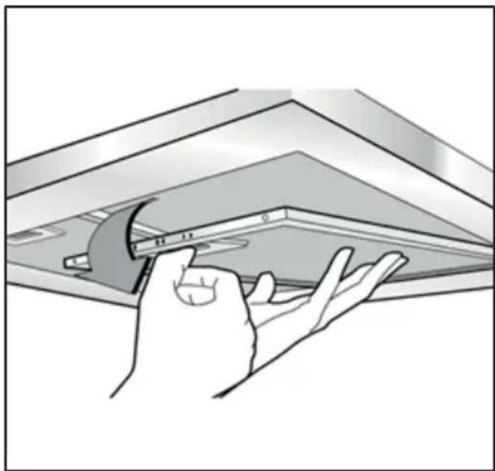
Before proceeding with the assembly operations, remove the anti-grease filter(s) (Fig.1) so that the unit is easier to handle.
- In the case of assembly of the appliance in the suction version prepare the hole for evacuation of the air.
natural_image
Illustration of a hand using a tool to clean or install a ceiling panel (no text or symbols visible)FIG.1
- We recommend the use of an air exhaust tube which has the same diameter as the air exhaust outlet hole. If a pipe with a smaller diameter is used, the efficiency of the product may be reduced and its operation may become noisier.
- If your appliance has been designed for use in habitations supplied with a centralised suction device perform the following operations:
- The switch controls opening and closure of a valve using a thermo electrical device. By placing the switch in the ON position, after a minute, the valve opens rotating 90° allowing suction of the stale air. By placing the switch in the OFF position, the valve closes after 100 seconds.
- Fixing to the wall:
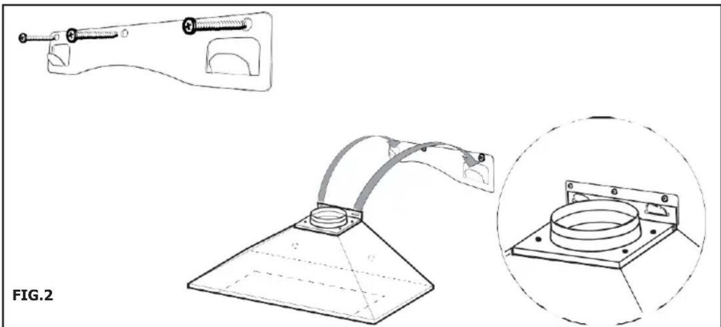
Drill 3 holes to accommodate the bracket (Fig.2). Screw and tighten the bracket onto the wall with the screws & screw plugs provided. Lift the cooker hood up and hang it onto the wall bracket hook (Fig.2).
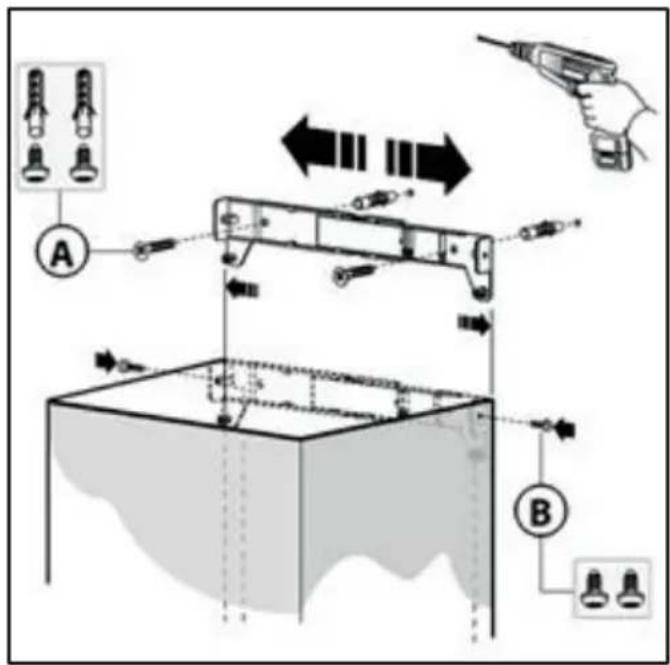
Fix the appliance to the wall and align it in horizontal position to the wall units. When the appliance has been adjusted, definitely fix the hood using the screws B (Fig.3). For the various installations use screws and screw anchors suited to the type of wall (e.g. reinforced concrete, plasterboard, etc.).
If the screws and screw anchors are provided with the product, check that they are suitable for the type of wall on which the hood is to be fixed.
natural_image
Technical line drawing of a mechanical device with two views: top shows a clamp and part with a curved handle, bottom shows a conical base with a circular opening (no text or symbols)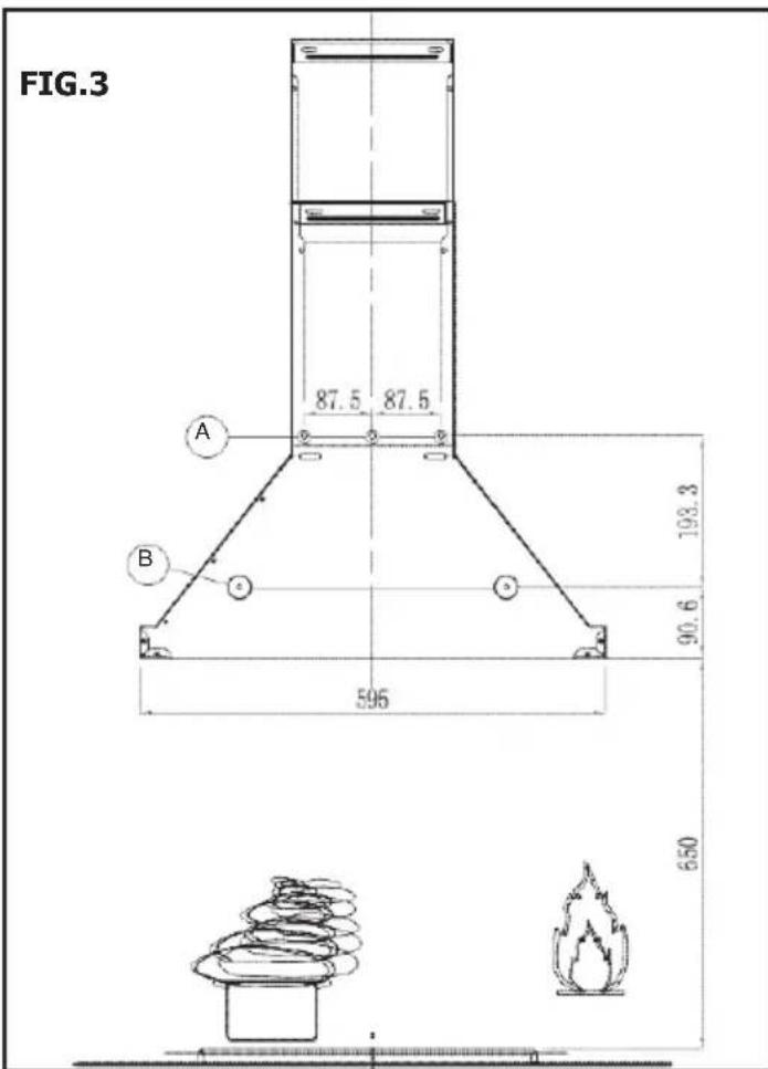
- Fixing the decorative telescopic flue:
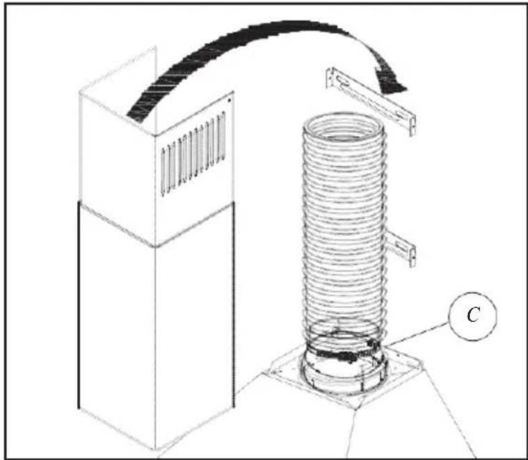
Arrange the electrical power supply within the dimensions of the decorative flue. If your appliance is to be installed in the ducting version or in the version with external motor, prepare the air exhaust opening. Adjust the width of the support bracket of the upper flue (Fig.5). Then fix it to the wall using the screws A (Fig.5) in such a way that it is in line with your hood and respecting the distance from the ceiling.
Connect the flange C to the air exhaust hole using a connection pipe (Fig.6). Insert the upper flue into the lower flue and rest above the frame. Extract the upper flue up to the bracket and fix it with the screws or hang the flue by matching both side blocks (Fig.7). To transform the hood from a ducting version into a filtering version, ask your dealer for the charcoal filters and follow the installation instructions.
natural_image
Technical line drawing of a mechanical assembly with a coiled spring and housing (no text or symbols)FIG.5 FIG.6
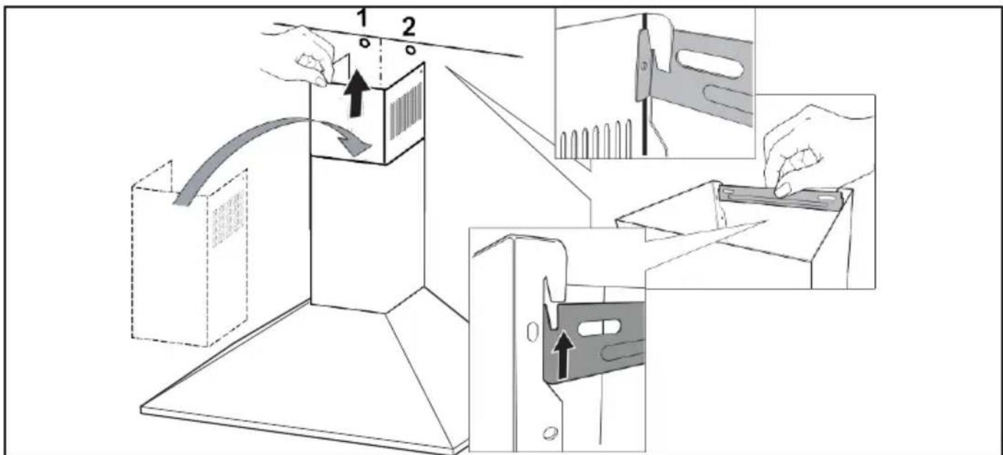
FIG.7
- Filtering version:
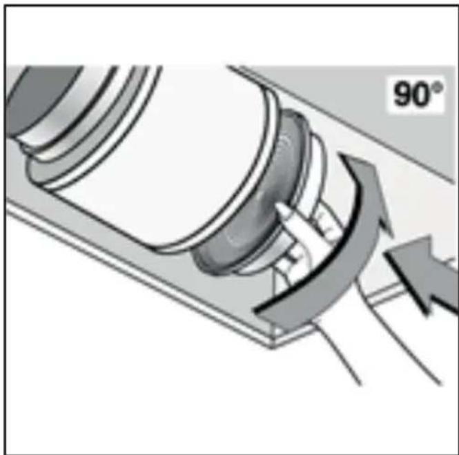
Install the hood and the two flues as described in the previous paragraph "Fixing the decorative telescopic flue". To assemble the filtering flue refer to the instructions contained in the kit. If the kit is not provided, order it from your dealer as accessory. The filters must be applied to the suction unit positioned inside the hood. They must be centred by turning them 90 degrees until the stop catch is tripped (Fig.8).
natural_image
Mechanical component diagram showing a rotating shaft and housing with directional arrows indicating motion (no text or symbols)FIG.8
Controls

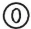
OFF button
Used for turning off the fan

Low Speed button
Starts the fan in low speed mode.
It is suitable for simmering and cooking which do not make much steam.
Medium Speed button
Starts the fan at medium speed.
This is ideal for ventilation during standard cooking operation.
High Speed button
Starts the fan in high speed.
This is ideal for when a high density of smoke or steam has been produced.

Light button
Used for turning on/off the light.
Before cleaning or maintenance switch off the electricity supply.
Replacing the LED Lights
If the appliance version is with LED lamps, the intervention of a specialised technician is necessary to replace them
Outer Casing
All external parts of the outer casing can be safely cleaned with a clean cloth wrung out in hot soapy water.
Do not use caustic pastes, abrasive cleaning powders, wire wool, hard implements or any products containing chlorides as they will damage the surfaces.
Stubborn marks can be removed using a stainless steel cleaner. We recommend that you clean the whole of the stainless steel area to maintain a uniform finish.
Sharp objects can mark the surface of stainless steel, but marks will become less noticeable with time.
To maintain the finish of the stainless steel, or to remove any greasy marks, wipe the stainless steel surface sparingly with a minimum amount of Baby Oil and kitchen paper.
Do not use cooking oils, as these may contain salt, which can damage the stainless steel surface.
Before cleaning or maintenance switch off the electricity supply.
To avoid any fire risk, the following cleaning instructions must be followed:
Grease Filters
The grease filters absorb grease and dust from cooking fumes, which would otherwise damage the inside of the hood.
The grease filters should be removed and cleaned regularly - with normal use, this should be every 2 months.
To clean use warm soapy water, or wash in a dishwasher. The grease filters may slightly change colour following washing, however this does not affect their performance.
Important: Frequent washing is essential to prevent a build-up of grease in the filters which could become a fire hazard.
- Remove the filters from the hood.
- Carefully wash the grease filters in hot soapy water and dry with a clean towel.
- Refit the clean filters.
Carbon Filters (models installed for use with the re-circulation method only)
The carbon filters absorb cooking odours and need renewing after about 6 months of normal use.
Replacement carbon filters can be obtained from our Customer Care (details at the rear of the handbook).
Saturation of the activated charcoal in the filter will depend on how often the hood is used, the type of kitchen and the regularity of cleaning the grease filter.
The carbon filters cannot be washed - renew every 6 months.
TECHNICAL DATA
Electricity Supply
230 - 240V \~ 50Hz
Classification
class II
Noise Level (External Venting)
Position 3 65 dBA
Position 1 45 dB
Light Bulbs
2 x 1.5W LED
Motor Rating
123W
Grease Filters
2 Off - Aluminium panel
Note: After cleaning, grease filters may lose their colour slightly - this does not affect their performance.
Carbon Filters
2 Off - Available as Spares
Extraction Rate (External)
Position 3 488,4 m³/h
Position 1 326,0 m³/h
Please keep this handbook in a safe place.
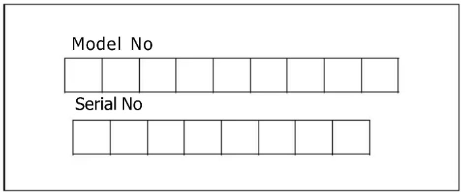
Please fill in the model number and serial number in the spaces provided below as they will assist us should you need to call.
0344 815 3746
When you dial this number you will hear a recorded message and be given a number of options. This indicates that your call has been accepted and is being held in a queue. Calls are answered in strict rotation as our Customer Care Representatives become available.
Enter appliance numbers here for future reference:
flowchart
graph TD
    A["Model No"] --> B[" "] --> C[" "] --> D[" "] --> E[" "] --> F[" "] --> G[" "]
    H["Serial No"] --> I[" "] --> J[" "] --> K[" "] --> L[" "] --> M[" "] --> N[" "]
These numbers can be found on your appliances. Outside the UK and Northern Ireland, refer to your local supplier.

Stoney Lane, Prescot, Merseyside, L35 2XW


- Contents
- Introduction
- Your first year Guarantee
- SAFETY PRECAUTION
- Warning!
- INSTALLATION INSTRUCTIONS
- Controls
- OFF button
- Low Speed button
- Medium Speed button
- High Speed button
- Light button
- Replacing the LED Lights
- Outer Casing
- Grease Filters
- TECHNICAL DATA
- Electricity Supply
- Classification
- Noise Level (External Venting)
- Light Bulbs
- Motor Rating
- Carbon Filters
- Extraction Rate (External)
- 815 3746
Brand : BELLING
Model : BEL 602 CHIM
Category : Range hood