VT-BP3 - Dash cam Boyo - Free user manual and instructions
Find the device manual for free VT-BP3 Boyo in PDF.


| Product Type | Dashboard Camera (Dash Cam) |
| Brand | Boyo |
| Model | VT-BP3 |
| Dimensions | Approx. 3.5 x 2.0 x 1.2 inches |
| Weight | Approx. 2.5 oz (70 g) |
| Power Source | 12V DC via cigarette lighter adapter |
| Battery | Built-in rechargeable Li-ion (approx. 200 mAh) |
| Video Resolution | Full HD 1080p (1920 x 1080) at 30 fps |
| Lens Angle | 120° wide angle |
| Display | 2.4-inch LCD screen |
| Storage | MicroSD card (up to 32 GB, Class 10 recommended) |
| Recording Modes | Loop recording, G-sensor triggered recording, manual recording |
| G-Sensor | Built-in 3-axis accelerometer for impact detection |
| GPS | Not included |
| Night Vision | Low-light enhancement with 4 IR LEDs |
| Parking Mode | Motion detection recording (requires hardwire kit, sold separately) |
| Audio | Built-in microphone and speaker |
| Mounting | Suction cup mount on windshield |
| Operating Temperature | -10°C to 60°C (14°F to 140°F) |
| Interface Languages | English, French, Spanish, etc. |
| Warranty | 1 year limited warranty |
| Included Accessories | 12V car charger, USB cable, suction mount, user manual |
Frequently Asked Questions - VT-BP3 Boyo
User questions about VT-BP3 Boyo
0 question about this device. Answer the ones you know or ask your own.
Ask a new question about this device
Download the instructions for your Dash cam in PDF format for free! Find your manual VT-BP3 - Boyo and take your electronic device back in hand. On this page are published all the documents necessary for the use of your device. VT-BP3 by Boyo.
USER MANUAL VT-BP3 Boyo
Birdview Rear Camera
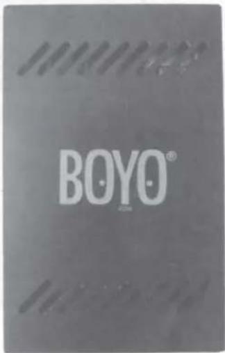
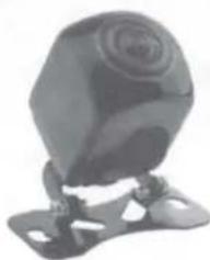
natural_image
Close-up of a black, textured object resembling a camera or sensor device (no visible text or symbols)Installation and Owner's Manual
Product Introduction
4D panoramic reversing assist system, through a single large wideview angle camera mounted behind the car, Collect images from the rear of the vehicle during the reversing and perform image distortion correction through "Image Distortion Restoration and Docking Technology" -> Perspective-> image stitching -> image enhancement and other processing, and finally form a 4D panorama. Reference information through real car model, the driver can easily identify the vehicle position, obstacle distance, surrounding environment and other factors to achieve fast and Safe reversing
BEFORE using this reversing system, please read the safety information provided in this user manual.
ALWAYS use the product as outlined in this user manual.
Product Accessories
Please check all the components listed below are in the kit
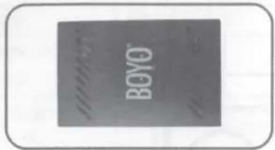
Part A
1 x Control module
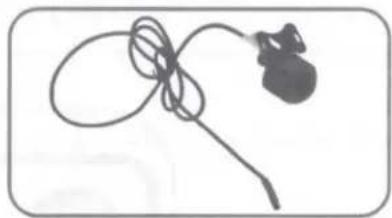
natural_image
Simple line drawing of a medical or laboratory device with a bulb and connector (no text or symbols)Part B
1 x Camera
natural_image
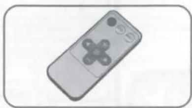
Illustration of a remote control with a diagonally crossed handle (no text or symbols)Part C
1 x Remote controller
natural_image
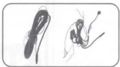
Two abstract line drawings resembling stylized hands or cables, no text or symbols presentPart D
2 x Main cables
natural_image
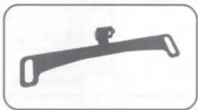
Simple black-and-white illustration of a mechanical lever or bracket (no text or symbols)Part E
1 x License plate bracket
natural_image
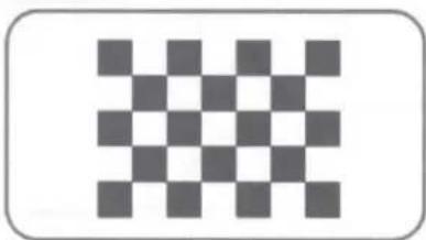
Checkerboard pattern with 12 squares arranged in a 3x3 grid (no text or symbols)Part F
1 x Calibration cloth
Product Accessories
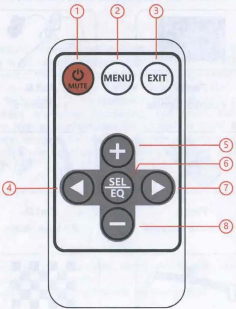
1.Reserved
5.UP
2.Menu
6.OK
3.Exit
7.Right
4.Left
8.Down
Product Specification
| Chipset | CPU-CortexA7,Dual-core,GPU -Mali400MP2 |
| Storage | Nand Flash |
| High speed memory | DDR3 |
| Calibration operation | Infrared remote control |
| Camera supply voltage | System control output:+5V/500mA |
| Signal format | AHD |
| Input detection signal | Reverse input detection |
| Output control | Control reverse output |
| Signal output format | CVBS |
| Operating temperature | -20°C ~ +70°C |
| Storage temperature | -40°C ~ +85°C |
| Storage relative humidity | 0% ~ 90% |
| System operating voltage | +12V |
| Working maximum current | 50mA,peak current<1A |
| PCBA size | 70.0 x 100.0 x 0.06(in) |
Installation
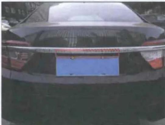
1. Installation Position
Reversing camera suggested position: Above edge of the car license plate, make sure that the camera is not in the way of the key switch of the truck.
natural_image
Rear view of a black sedan with a blue license plate, parked outdoors (no visible text or symbols)2.Attentions
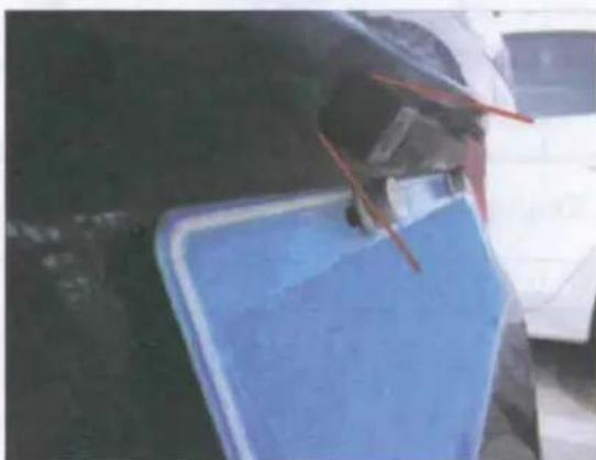
1) Install the camera in a position where there is no object blocking the front view. Secure it to avoid any vibration.
natural_image
Close-up of a blue plastic sheet being held by red chopsticks, with a white car in the background (no visible text or symbols)2) Choose flat ground with good light as alignment site to place calibration cloth.
Specification:size 14.4ft*3.9ft black and white squares size 7.8in*7.8in edge 3.9in
Installation
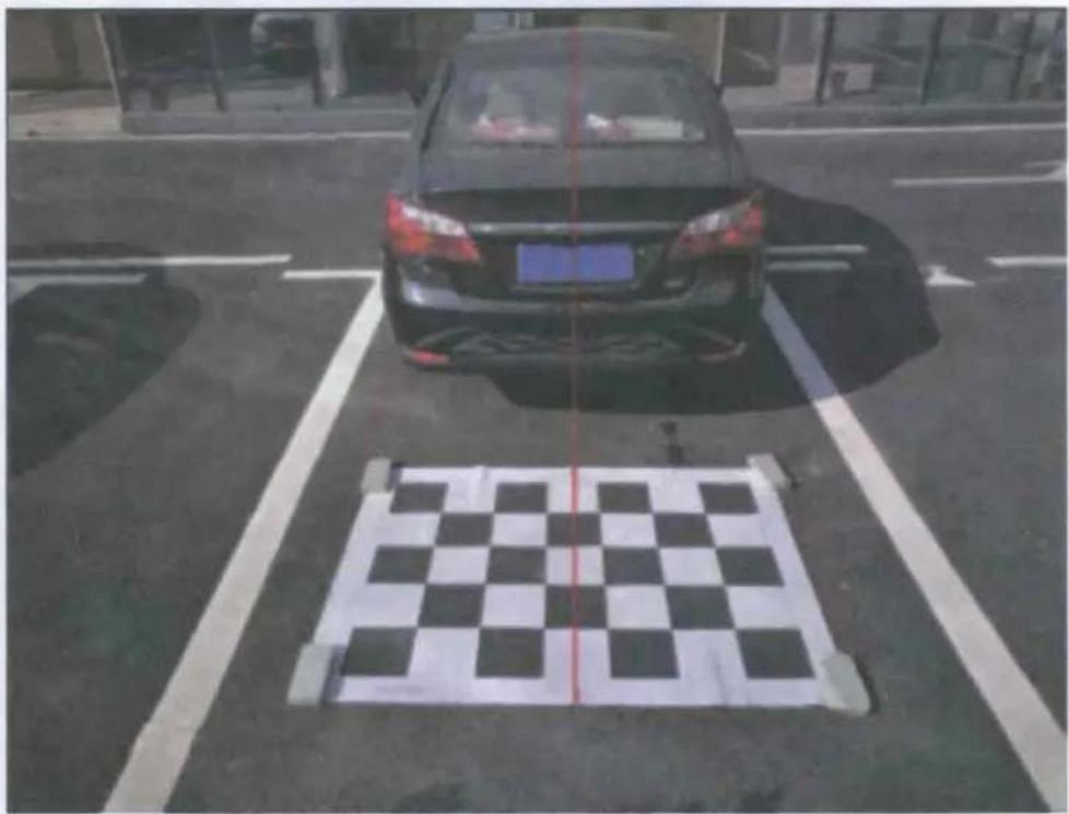
- Put the calibration cloth on the back of the car, Calibrate the centerline of the cloth to align the vertical centerline of the car, the left and right sides are parallel to the rear wheel. (refer to picture below)
natural_image
Black and white photo of a car parked on a street with a checkered pavement marked (no text or symbols visible)Installation
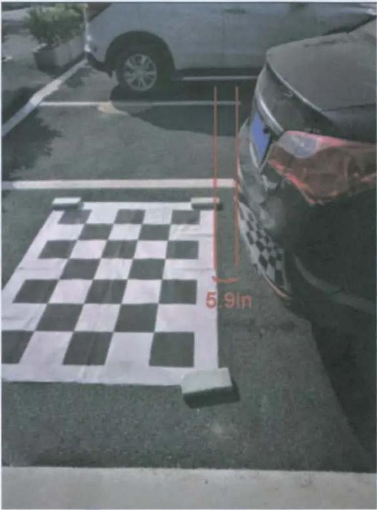
- Put the edge of calibration cloth parallel to the edge of car trail, and keep 5.9 inch distance (as below picture), make sure the camera can observe the edge of the car calibration cloth
Software adjustment
1. Enter calibration settings
First entry: When the software interface is not displayed, you can enter the software calibration interface setting by long pressing the remote control to set the red button.
2、Camera calibration
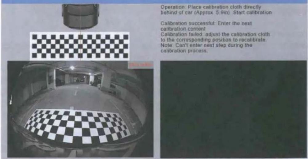
After the calibration cloth is placed as shown above, when the video on the right side of the screen is almost the same as the effect image, the edge of the black and white grid of the calibration cloth corresponds to the disappearing position, click the software to start the calibration button.
After the calibration has started, the software performs the calibration function, and the video interface displays the calibration, then wait for the calibration to be completed.
Calibration status:
Calibration successful: When the interface prompts calibration is complete, go to the next calibration setting via the remote control.
Calibration failed: When the interface prompts that the calibration fails, please adjust the calibration cloth according to the corresponding position and click again to start calibration. Reason for failure:
Reason for failure
1) The floor is not flat enough and no enough light
2) There is an item above the black and white grid of the calibration cloth to block the identification of the calibration cloth.
3) The black and white grid of the calibration cloth is not clear enough with much folds.
Software adjustment
The following figure is the effect of the camera centered installation. When not centered, the effect is slightly different and is not affected.
Camera
Software adjustment
3. Image offset calibration
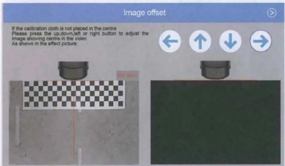
When the camera position is not centered, the calibration cloth position needs to be adjusted in the actual video screen on the right. Adjust the position of the calibration cloth in the video by the up, down, left and right buttons, to adjust the position of the calibration cloth in the centre of the video image.
Software adjustment
4、Car parameters calibration
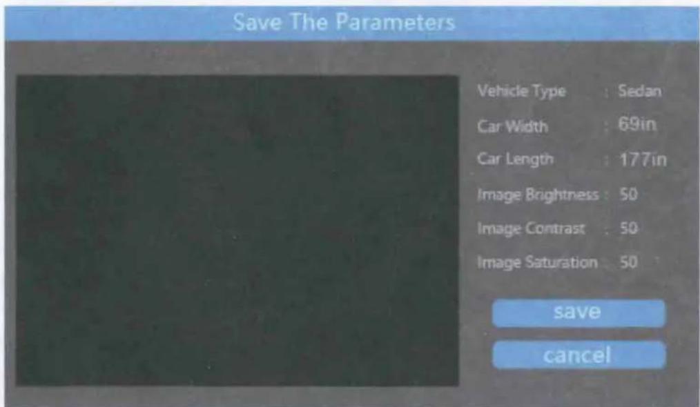
Please modify the following car properties according to the actual model and parameters.
Body width range 55\~98 in
Car default 67in
SUV default 70.9in
Other default 82.7in
Body length range is 126.0\~216.5in
Car default 189.0in
SUV default 196.9in
Other default 196.9in

Software adjustment
5、Image parameter calibration
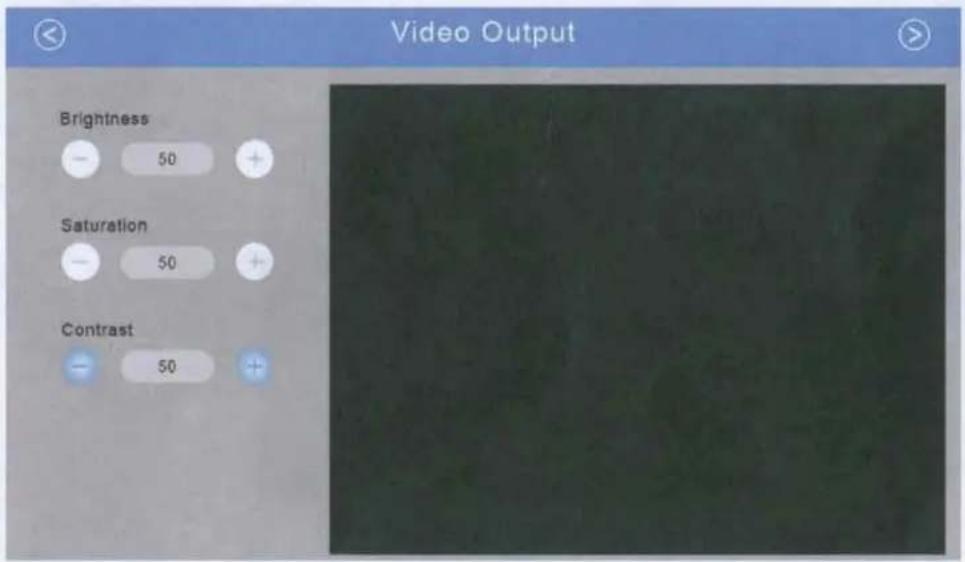
The camera screen can adjust the brightness, contrast, and saturation range from 0 to 100. Default 50
Please adjust the corresponding parameters according to the actual screen effect (the default effect of the parameters is the best, non-image color sensitive people, it is recommended to use the default value)
Software adjustment
6、Video cropping
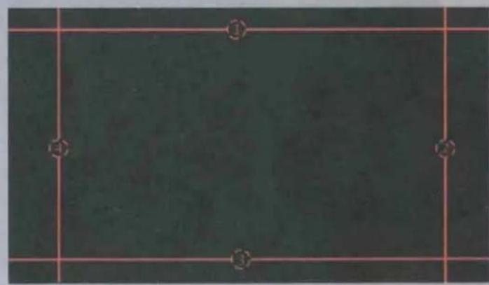
This page is cropped by the marker line and finally displays the image size behind the reversing interface.
The remote control selects the marking line (blue effect) by up, down, left and right. When you need to adjust a certain marking line, click the OK button (the marking line is red effect), then move to the ideal position, and click the OK button again to exit the adjustment.
Image Cropping
natural_image
Dark greenboard with white grid lines and numbered markers (①, ②, ③) at corners, no readable text or symbols.Adjust line 1 2 3 4 to define the final video zone.
Status Description:
Selected Status (Blue)
Selected Status (Red)
Operation Method: Choose the number with the up,down,left, right button,press the OK button to enter editing mode,press OK button again to exit.
Software adjustment
7、Parameter saving
When all parameters have been calibrated. Preview the actual effect of the video screen and confirm that the parameters on the right side are correct and save the parameters. When an error occurs, click the Cancel button to recalibrate
Software settings menu description
Standby time: refers to the non-reversing gear position, and after the specified time, the panoramic reversing system will exit.
System type: CVBS output type, default N system
Panorama position: the position of the reversing panorama can be switched, the default left
BOYO®
VISION
Vision Tech America, Inc.
1452 E. Valencia Dr, Fullerton, CA 92831
Ph: 888-941-3060
www.visiontechamerica.com
1 YEAR LIMITED WARRANTY
This limited warranty is given to the end-user or the retail purchaser (referred to this warranty as "Original Purchaser") that it will be free from defects in material and workmanship for a period of one year from the date of the purchase of the new product (excluding accessory items such as power cords, cradle, memory card, adaptor and cables). A copy of the original proof of purchase and this warranty card with RMA number given by Vision Tech America, Inc. is required to receive warranty service. In the unlikely event that the new product should fail due to defect in material or workmanship, Vision Tech America, Inc. will repair or replace with new or refurbished product, where each party will be responsible for one-way shipping for the lower 48 states customers only. For International and U.S customers residing in Hawaii, Alaska and Puerto Rico, customer is responsible for freight charges incurred both ways.
This limited warranty does not cover any physical damage to this product, damage caused by improper installation; improper use; misuse; neglect; repair of cracked, scratched, broken or modified cosmetics; or parts that have been altered or removed; damages done by another device used with this product resulting from use of non BOYO®- brand parts. This warranty is VOID if you purchased this product as used, floor model sample, or refurbished; if the product has been altered or modified in any way (including but not limited to attempted repair without authorization from BOYO®- Vision Tech America, Inc. and/or alteration/removal of the serial number). This limited warranty does not cover the vehicle of any damages or liabilities in which this product is installed or being installed. This product does not guarantee avoidance of vehicle collision or accident.
If you are having trouble with the product, please contact our technical support at 888-941-306Q or email: info@visiontechamerica.com with your questions or comments. If your product is eligible to receive warranty, request for warranty service online by visiting http://visiontechamerica.com/site/get-warranty/
This warranty is invalid if the factory applied serial number has been altered or removed from the Product.
IMPORTANT: TO SEND DEFECTIVE PRODUCT FOR WARRANTY SERVICE, YOU MUST RECEIVE RMA (RETURN MATERIAL AUTHORIZATION) AND INCLUDE ORIGINAL PROOF OF PURCHASE AND THIS WARRANTY CARD WITH THE SHIPMENT.
VISION TECH AMERICA CUSTOMER SERVICE CENTER
888-941-3060 or visit www.visiontechamerica.com
For an accessory or part not available from your authorized dealer, call
For U.S. 888-941-3060 | International 714-446-0543
- Birdview Rear Camera
- Product Introduction
- Product Accessories
- Product Specification
- Installation
- Installation Position
- 2.Attentions
- Software adjustment
- Enter calibration settings
- 2、Camera calibration
- Calibration status:
- Reason for failure
- Camera
- Image offset calibration
- 4、Car parameters calibration
- 5、Image parameter calibration
- 6、Video cropping
- 7、Parameter saving
- YEAR LIMITED WARRANTY
Brand : Boyo
Model : VT-BP3
Category : Dash cam