
MPX-MD92 - MiniDisc player SANYO - Free user manual and instructions
Find the device manual for free MPX-MD92 SANYO in PDF.


| Product type | MiniDisc player |
| Brand | SANYO |
| Model | MPX-MD92 |
| Color | Black and white |
| Dimensions (W x H x D) | 430 x 100 x 300 mm |
| Weight | 3.5 kg |
| Power supply | Mains 220-240 V, 50/60 Hz |
| Power consumption | 15 W |
| Supported formats | MiniDisc (MD) |
| Playback functions | Play, pause, stop, skip forward/backward, random play, repeat |
| Programming | Track programming up to 20 tracks |
| Audio outputs | RCA line output, stereo headphone jack |
| Audio inputs | RCA line input for recording |
| Display | LCD screen with time, track indicators, etc. |
| Remote control | Infrared remote control included |
| Maintenance and cleaning | Use a soft, dry cloth. Do not use solvents or abrasive products. |
| Safety | Do not expose to humidity or extreme temperatures. Unplug during thunderstorms. |
| Spare parts and repairability | Contact an authorized SANYO service center for any repairs. |
| General information | 55-page user manual available for free download. |
Frequently Asked Questions - MPX-MD92 SANYO
User questions about MPX-MD92 SANYO
0 question about this device. Answer the ones you know or ask your own.
Ask a new question about this device
Download the instructions for your MiniDisc player in PDF format for free! Find your manual MPX-MD92 - SANYO and take your electronic device back in hand. On this page are published all the documents necessary for the use of your device. MPX-MD92 by SANYO.
USER MANUAL MPX-MD92 SANYO
INSTRUCTION MANUAL MANUEL D'INSTRUCTIONS MANUAL DE INSTRUCCIONES
MPX-CD92 MPX-MD92
Multiplexer
English
Multiplexeur
Français
Multiplexor
Español
natural_image
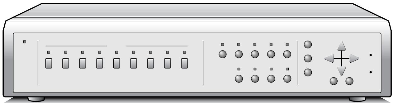
Front view of a silver server rack with indicator lights and control buttons (no text or symbols visible)About this manual
- Before installing and using this unit, please read this manual carefully. Be sure to keep it handy for later reference.
- This manual gives basic connections and operating instructions for 2 models (Color MPX-CD92, B/W MPX-MD92).
WARNING: To reduce the risk of fire or electric shock, do not expose this appliance to rain or moisture.
CAUTION: Changes or modifications not expressly approved by the manufacturer may void the user's authority to operate this equipment.

The lightning flash with arrowhead symbol, within an equilateral triangle, is intended to alert the user to the presence of uninsulated “dangerous voltage” within the product’s enclosure that may be of sufficient magnitude to constitute a risk of electric shock to persons.

The exclamation point within an equilateral triangle is intended to alert the user to the presence of important operating and maintenance (servicing) instructions in the literature accompanying the product.
This equipment has been tested and found to comply with the limits for a Class B digital device, pursuant to part 15 of the FCC Rules. These limits are designed to provide reasonable protection against harmful interference in a residential installation. This equipment generated, uses and can radiate radio frequency energy and, if not installed and used in accordance with the instructions, may cause harmful interference to radio communications. However, there is no guarantee that interference will not occur in a particular installation. If this equipment does cause harmful interference radio or television reception, which can be determined by turning the equipment off and on, the user is encouraged to try to correct the interference by one or more of the following measures:
- Reorient or relocate the receiving antenna.
- Increase the separation between the equipment and receiver.
- Connect the equipment into an outlet on a circuit different from that to which the receiver is connected.
- Consult the dealer or an experienced radio/TV technician for help.
For the customers in Canada
This class B digital apparatus complies with Canadian ICES-003.
CAUTION
Danger of explosion if battery is incorrectly replaced. Replace only with the same or equivalent type recommended by the manufacturer. Discard used batteries according to the manufacture's instructions.
Declaration of Conformity
Model Number : MPX-CD92/MD92 Trade Name : SANYO Responsible party : SANYO FISHER COMPANY Address : 21605 Plummer Street, Chatsworth, California 91311 Telephone No. : (818) 998-7322
- This device complies with Part 15 of the FCC Rules. Operation is subject to the following two conditions:
(1) this device may not cause harmful interference, and
(2) this device must accept any interference received, including interference that may cause undesired operation.
Location
For safe operation and satisfactory performance of your unit, keep the following in mind when selecting a place for its installation:
- Shield it from direct sunlight and keep it away from sources of intense heat.
- Avoid dusty or humid places.
- Avoid places with insufficient ventilation for proper heat dissipation. Do not block the ventilation holes at the top and bottom of the unit. Do not place the unit on a carpet because this will block the ventilation holes.
• Install the unit in a horizontal position only. - Avoid locations subject to strong vibrations.
- Avoid moving the unit between cold and hot locations.
- Do not place the unit directly on top of a monitor TV, as this may cause playback or recording problems.
Avoiding Electrical Shock and Fire
- Do not handle the power cord with wet hands.
- Do not pull on the power cord when disconnecting it from an AC wall outlet. Grasp it by the plug.
- If any liquid is spilled on the unit, unplug the power cord immediately and have the unit inspected at a factory-authorised service centre.
- Do not place anything directly on top of this unit.
SERVICE
This unit is a precision instruments and if treated with care, will provide years of satisfactory performance. However, in the event of a problem, the owner is advised not to attempt to make repairs or open the cabinet. Servicing should always be referred to your dealer or Sanyo Authorized Service Center.
CONTENTS
PARTS NAMES ....3
FRONT PANEL ....3
REAR PANEL 4
CONNECTION ....5
BASIC CONNECTIONS ....5
CONNECTIONS TO THE S-VIDEO
TERMINALS ....5
CONNECTIONS TO THE ALARM IN AND
RS232C/RS485 TERMINALS 6
REMOTE CONTROLLER CIRCUIT
CONNECTIONS....7
BASIC OPERATIONS ....8
MODE SWITCHING ....8
SECURITY LOCK FUNCTION .....9
SETTINGS BACKUP FUNCTION .....9
RESET FUNCTION 9
LIVE PICTURE MODE ....10
FULL SCREEN OPERATIONS .....12
4 DIVISIONS SPLIT SCREEN OPERATIONS ....14
MULTI-DISPLAY SCREEN OPERATIONS .....15
4 DIVISIONS SPLIT SCREEN OPERATIONS ....22
MULTI-DISPLAY SCREEN OPERATIONS .....23
PLUS-DISPLAY SCREEN OPERATIONS .....23
MENU SETTING MODE ....25
LANGUAGE SETTING .....26
CLOCK AND DAYLIGHT SAVING SETTING .....27
VCR SETTING AND EXTERNAL CONTROL
COMMUNICATION SPEED SETTING .....29
ALARM AND SENSOR SETTING .....31
ACTIVE RECORDING AND VIDEO LOSS
SETTING 33
MONITOR SETTINGS ....35
CAMERA SETTING ....36
SETTING EACH CAMERA DISPLAY POSITION
IN SPLIT SCREEN DISPLAY MODE ....43
CLOCK AND TITLE DISPLAY SETTINGS .....44
ALARM DATA DISPLAY 45
ALARMS OPERATIONS ....46
INTERFACE SPECIFICATIONS .....48
SPECIFICATIONS ....53
FEATURES
Using this unit you can display the live pictures from the cameras in split screen display mode (9 or 4 divisions) while recording, and the recorded pictures can also be displayed in split screen display mode.
- High-speed switching (up to single field switching)
- 1, 4, 9 screens display modes, with possibility of displaying an automatic sequential live or recorded pictures display in the bottom right 1/4 of the screen while in 9 split screen display mode.
- Full screen display on monitor 2 and during alarms automatic switching to the alarm screen.
- The following operations are possible at each camera according to the timer settings:
- Programmed recording of certain or all cameras only can be done according to the day or night periods.
- Different alarm durations of certain or all cameras can be set according to the day or night periods.
- Live or recorded pictures of certain or all cameras can be masked so they are not visible according to the day or night periods.
- Automatic switching delay can be set for each camera according to the day or night periods.
- Video sensor points areas can be set for each camera. Trigger can start alarm recording operations in priority.
- If the video signal is interrupted at any of the cameras, the frozen image just previous to the interruption or color bars can be displayed (selectable for each camera).
- The unit can be controlled by computer through the RS232C connection.
- A system controller (sold separately) can be used through the RS485 (RJ-11) connection.
- 2 monitors output and S-VIDEO input/output. (MPX-CD92 model only)
- Up to 100 alarm entries can be displayed on-screen.
ACCESSORIES
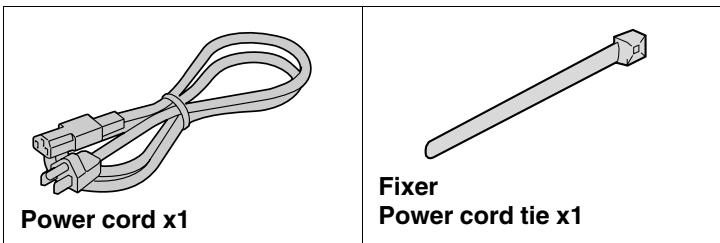
To mount this unit onto a rack, please use the rack mount hardware sold separately.
FRONT PANEL
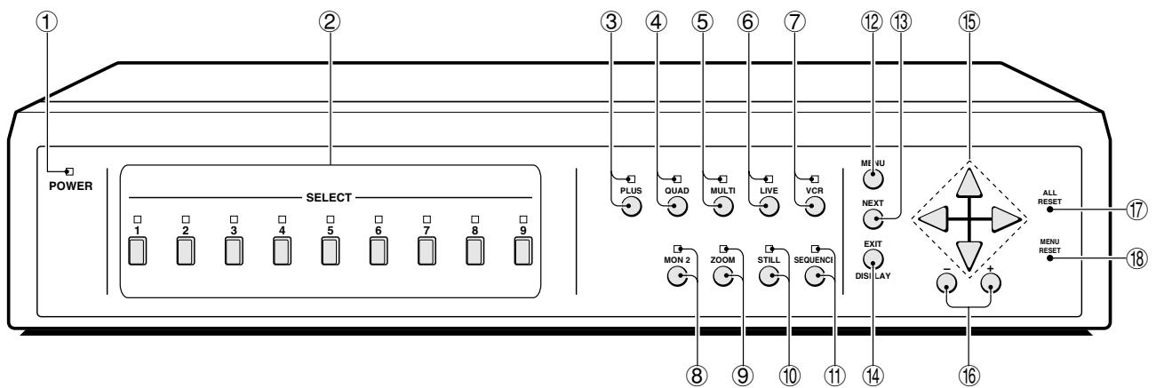
This unit is not equipped with a power switch. The power is turned on/off when the supplied power cord is connected/disconnected at the power source.
① POWER indicator
② Camera SELECT buttons and camera indicators
Use these buttons to select the picture from the corresponding camera. Also, when in still image, sequential display, 4 divisions split screen or multi-display screen modes, press one of these buttons to return to the normal picture full screen display of the corresponding camera.
③ PLUS button and indicator
④ QUAD button and indicator
In sequential display, full screen display or multi-display screen modes, press this button to switch to 4 divisions display screen. Press repeatedly to switch to subsequent 4 divisions screens.
⑤ MULTI button and indicator
⑥ LIVE button and indicator
Press this button to select the live input mode.
⑦ VCR button and indicator
Press this button to select the VCR playback input mode.
⑧ MON 2 button and indicator
Press this button to set the output at monitor 2.
⑨ ZOOM button and indicator
In full screen display mode, press this button for a 2x zoomed in image. Press the button one more time to cancel.
⑩ STILL button and indicator
In full screen display mode, press this button to freeze the displayed image. Press the button one more time to cancel.
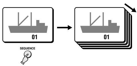
⑪ SEQUENCE button and indicator
In 4 divisions split screen or full screen display modes, press this button for an automatic sequential full screen display of the pictures.
⑫ MENU button (see page 8)
Press this button to display the menus. Press repeatedly to select the different menus in order.
⑬ NEXT button
⑭ EXIT/DISPLAY button
⑮ ▲, ▼, ▶, ◀ button
⑯ +, - button
⑰ ALL RESET button (see page 9)
⑱ MENU RESET button (see page 9)
In order to keep the unit internal temperature low, a fan is provided on the side of the unit. If the fan does not operate properly, the POWER indicator will flash to indicate a problem. Unplug the unit from the power supply and check to make sure nothing is obstructing the fan. If after the power is restored to the unit, the POWER indicator still flashes, do not use the unit and consult your dealer.
REAR PANEL
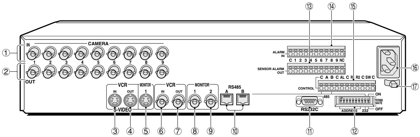
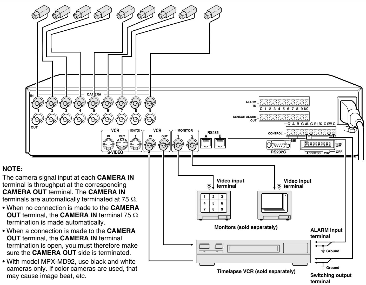
① CAMERA IN terminals (1 – 9)
② CAMERA OUT terminals (1 – 9)
Each camera signal is output directly at these terminals.
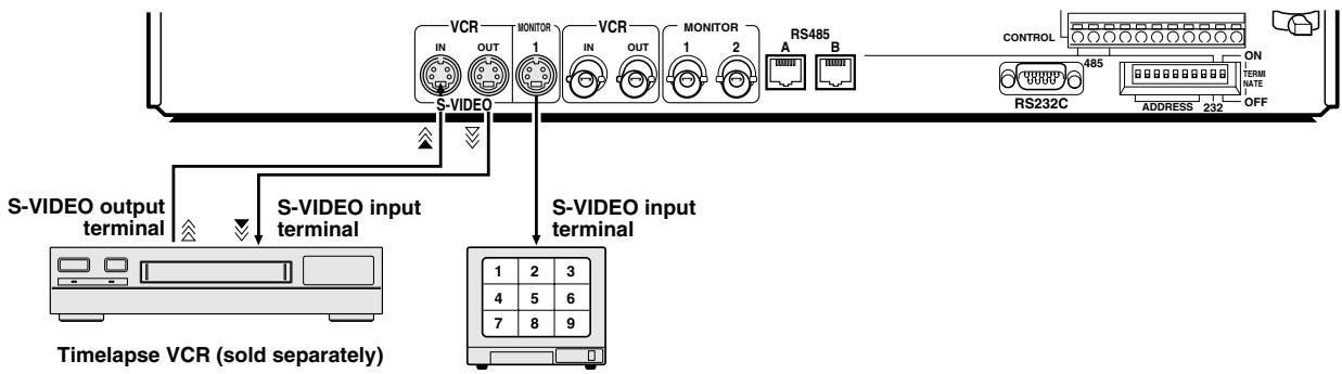
③ S-VIDEO VCR IN (VCR S-VHS signal input) terminal
④ S-VIDEO VCR OUT (VCR S-VHS signal output) terminal
NOTE: Model MPX-MD92 does not have S-VIDEO IN, OUT terminals.
⑤ MONITOR 1 (Monitor 1 S-VHS signal output) terminal
NOTE: Model MPX-MD92 does not have S-VIDEO MONITOR 1 terminal.
⑥ VCR IN (Video cassette recorder input) terminal
⑦ VCR OUT (Video cassette recorder output) terminal
⑧ MONITOR 1 (Monitor 1 output) terminal
⑨ MONITOR 2 (Monitor 2 output) terminal
⑩ RS-485 control ports (RS485 A, B)
(A) RJ-11 A terminal
Used for connection with a modular cable.
(B) RJ-11 B terminal
Used for connection with a modular cable.
Note: • Do not connect to a phone line.
- Only up to two RS-485 control ports can be used.
- Do not use all of the RS-485 control ports.
⑪ RS-232C (RS232C) terminal
To control this unit using a personal computer, connect the computer serial terminal to this terminal using a 9-pin D-SUB cable (sold separately).
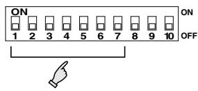
⑫ Interface setting DIP switches (ADDRESS, RS-232, RS-485, TERMINATE)
⑬ SENSOR ALARM OUT terminals (1 – 9)
⑭ ALARM IN (Alarm signal input) terminals
The alarm triggers input to the unit are output at the AL pin of the CONTROL terminal.
⑮ CONTROL terminal
| Pin | Signal |
| C | Ground |
| A | RS485 terminal * |
| B | RS485 terminal * |
| C | Ground |
| AL | Alarm output (DC 5V) |
| C | Common |
| R1 | Remote input 1 |
| R2 | Remote input 2 |
| C | Common |
| SW | Switching input (DC 5V) |
| C | Ground |
* Used for connection with a twisted-pair cable.
⑯ AC Power socket (AC IN\~)
Insert the power cord female plug firmly into this socket.
When the other plug of the power cord is connected to a live power source, the POWER indicator on the front panel will light.
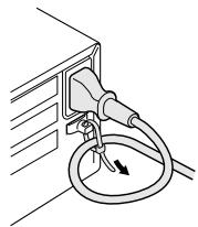
⑰ Power cord holder
Using the supplied tie, attach the power cord to the holder as illustrated.
CONNECTION
Before making any connection, make sure all the devices are turned off.
Before making the connections, please refer to the instruction manual accompanying each device. If the devices are not connected properly, that may cause a fire and/or damages.
BASIC CONNECTIONS
CONNECTIONS TO THE S-VIDEO TERMINALS
If connections are made to the S-VIDEO terminals, they will have the priority.
flowchart
graph TD
    A["S-VIDEO output terminal"] --> B["S-VIDEO input terminal"]
    B --> C["Timelapse VCR (sold separately)"]
    D["VCR IN MONITOR 1"] --> E["S-VIDEO input terminal"]
    F["VCR OUT MONITOR 1"] --> G["S-VIDEO input terminal"]
    H["RS485 A B"] --> I["S-VIDEO input terminal"]
    J["CONTROL 485"] --> K["ADDRESS 212"]
    L["ON TERM NATE OFF"] --> M["Power Supply"]
    style A fill:#f9f,stroke:#333
    style B fill:#ccf,stroke:#333
    style C fill:#cfc,stroke:#333
    style D fill:#fcc,stroke:#333
    style E fill:#cff,stroke:#333
    style F fill:#ffc,stroke:#333
    style G fill:#ffc,stroke:#333
    style H fill:#ffc,stroke:#333
    style I fill:#cfc,stroke:#333
    style J fill:#fcc,stroke:#333
    style K fill:#fcc,stroke:#333
    style L fill:#fcc,stroke:#333
    style M fill:#fcc,stroke:#333
CONNECTIONS TO THE ALARM IN AND RS232C/RS485 TERMINALS
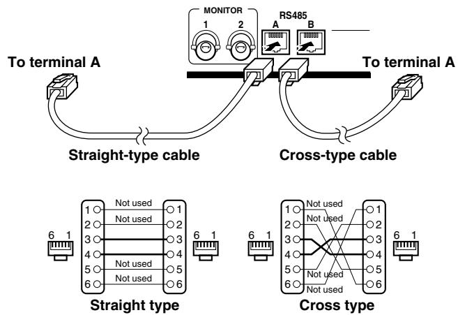
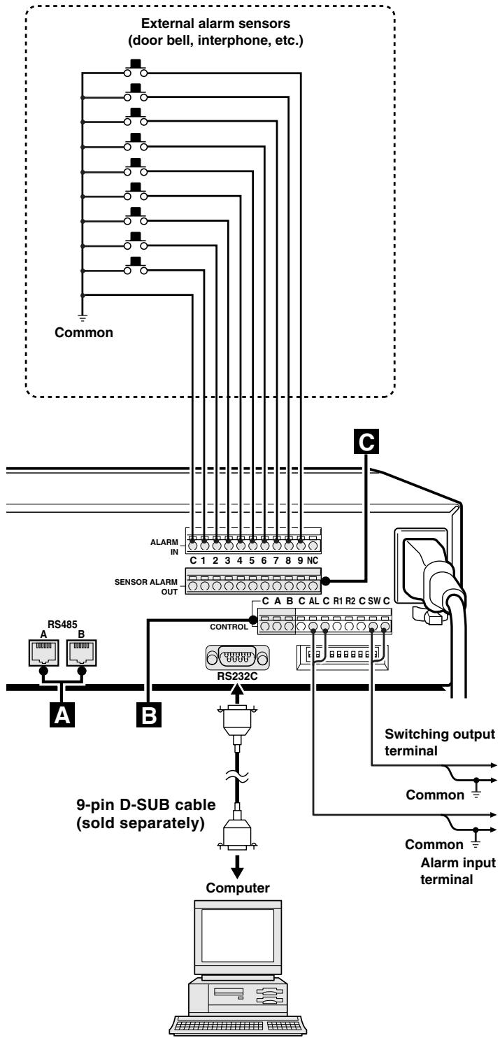
A RS485 (RJ-11) terminal connection
Make the connection to the RS485 control terminal using a modular cable (sold separately).
- If using a straight type cable, connect it between the A terminals, or between the B terminals (see illustration below).
- If using a crossed type cable, connect it from the A terminal to the B terminal, or from the B terminal to the A terminal (see illustration below).
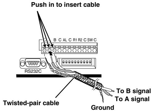
B Using the push-lock terminals
Make the connections to pins A, B, C (Ground) of the CONTROL terminal using a twisted-pair cable (sold separately). Then, connect signal A to A, and signal B to B.
C SENSOR ALARM OUT terminals
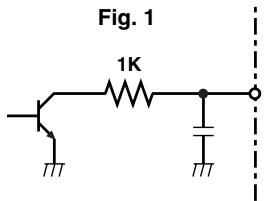
When the unit internal video sensor send a trigger, it will be output at the SENSOR ALARM OUT terminals. By connecting indicator lamps switching circuits to theses connectors (Fig. 1), an indication can be generated when the video sensors send a trigger.
For example, the video sensor alarm indicator lamps could be laid out on a factory floor plan to give accurate indication of trigger location. The terminals are normally open (NO). A trigger at the video sensor for one of the cameras, will switch the signal to LOW.
Rating values for each connector (at 25°C)
• Maximum current : 25 mA
• Maximum voltage : 25 V
• Maximum power : 40 mW
flowchart
graph TD
    A["Common"] --> B["External alarm sensors (door bell, interphone, etc.)"]
    B --> C["SENSOR ALARM OUT"]
    C --> D["RS485 A"]
    C --> E["RS232C"]
    D --> F["Switching output terminal"]
    E --> G["Switching output terminal"]
    F --> H["Computer"]
    G --> H
    I["Common Alarm input terminal"] --> H
    J["ALARM IN"] --> K["C 1 2 3 4 5 6 7 8 9 NC"]
    K --> L["C A B C AL C R1 R2 C SW C"]
    M["CONTROL"] --> N["RS232C"]
    style A fill:#f9f,stroke:#333
    style B fill:#ccf,stroke:#333
    style C fill:#cfc,stroke:#333
    style D fill:#fcc,stroke:#333
    style E fill:#cff,stroke:#333
    style F fill:#ffc,stroke:#333
    style G fill:#ffc,stroke:#333
    style H fill:#cfc,stroke:#333
    style I fill:#fcc,stroke:#333
    style J fill:#fcc,stroke:#333
    style K fill:#cfc,stroke:#333
    style L fill:#cfc,stroke:#333
    style M fill:#fcc,stroke:#333
    style N fill:#cfc,stroke:#333
Connect a 9-pin D-SUB cable (sold separately) from the RS232C terminal on the rear panel to the computer serial connector.
REMOTE CONTROLLER CIRCUIT CONNECTIONS
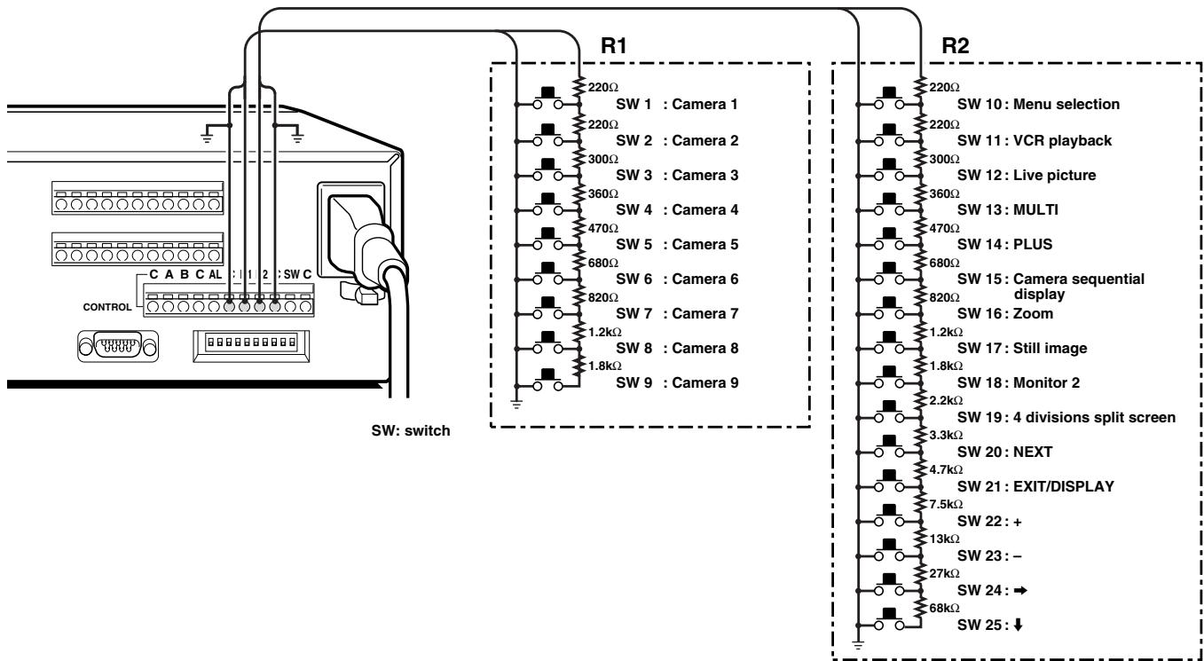
Use the layout below to make a remote controller and make the connections to the remote input pins (R1, R2) of the CONTROL terminal as indicated. This will permit remote controlled operation of this unit. (make contact LOW input)
When the unit is connected to a power source, the default display mode will be as follows: live picture displayed in a 9 divisions split screen on monitor 1, and sequentially, full screen on monitor 2. You can use the VCR, MENU and LIVE buttons to switch to the desired mode on monitor 1 (see below for further information). When the power is restored after having already used the unit, the unit will restart in the modes selected before the unit was turned off.
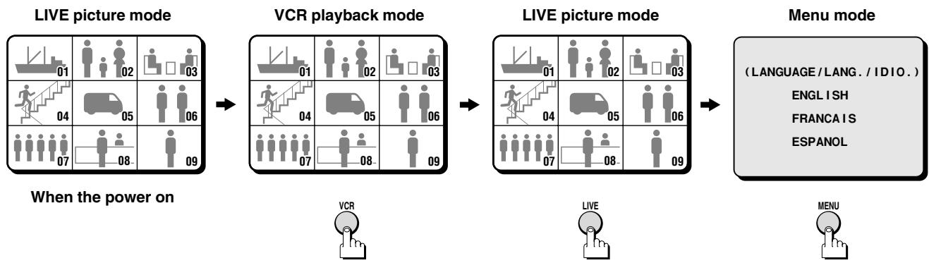
(LANGUAGE/LANG./IDIO.)
ENGLISH
FRANCAIS
ESPANOL
Live Picture Mode (see page 10)
When the LIVE button is pressed, the live (direct) picture from the cameras connected to the camera input terminals (1 – 9) on the unit rear panel, will be displayed on monitor 1. While in live picture mode you can use the still and zoom functions.
NOTE:
- The unit will automatically start in the live picture or VCR playback display mode (9, 4 divisions split screen, full screen or sequential display) last selected. Therefore, when a mode is selected, the display mode will remain the same.
- If a camera is not connected at one of the input terminals, "NO VIDEO" will be displayed on the monitor 1 screen.
NO VIDEO
VCR Playback Mode (see page 18)
Start playback on the VCR. If the video signal is correctly recorded, the VCR playback image will be displayed on monitor 1 when the VCR button is pressed. While in VCR playback mode you can use the still and zoom functions.
NOTE: If playing back a tape not recorded through this unit, "NO ID" will be displayed on the monitor screen.
NO ID
NOTE: In live picture mode and VCR playback mode there may be a slight vertical roll of the picture.
Menu Setting Mode (see page 25)
① Press the MENU button to display the menu
The buttons used for menu control are indicated below.
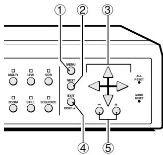
② NEXT button
To select a sub-menu (in the (CAMERA SET), (POSITION SET), (DISPLAY SET) menus) in order to set the title position, etc. Press the NEXT button to switch between the menu and the sub-menu.
- ▲ button: will move the cursor up.
- ▼ button: will move the cursor down.
- button: will move the cursor towards the right.
- ◀ button: will move the cursor towards the left.
④ EXIT/DISPLAY button (see page 9)
To exit the menu mode and return to live picture mode.
Also, when in live picture mode or VCR playback mode, press this button to switch the display of the camera title and the clock display on/off.
⑤ +, - buttons...press repeatedly
-
- button: for forward selection of numbers, letters, symbols.
- – button: for backward selection of numbers, letters, symbols.
SECURITY LOCK FUNCTION
This function lets you lock the camera live picture mode or VCR playback mode, so that it cannot be switched to another mode.
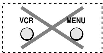
Camera Live Picture Mode Lock
Press the LIVE button for about 3 seconds.
A buzzer will be heard, and the VCR and MENU buttons will not operate if pressed. If buttons are pressed, a buzzer will be heard and the operation will not be possible.

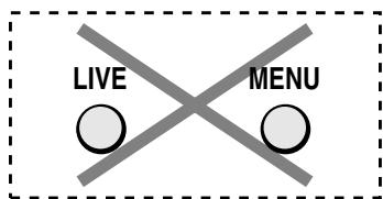
VCR Playback Mode Lock
Press the VCR button for about 3 seconds.
A buzzer will be heard, and the LIVE and MENU buttons will not operate if pressed. If buttons are pressed, a buzzer will be heard and the operation will not be possible.

Canceling the Security Lock
To cancel the security lock, press the same button again for about 3 seconds. A buzzer will be heard and the mode will be unlocked.
SETTINGS BACKUP FUNCTION
This unit bottom is equipped with a backup battery (lithium battery) to maintain the clock settings. When the unit is used under normal conditions, the backup battery is recharged. The battery is fully recharged after a minimum of about 30 hours, and will maintain the clock settings for up to 30 days.
NOTE: The settings may not be maintained properly if the backup battery has been recharged for less than 30 hours when the power goes off.
Battery Life
If the power is turned off for about one hour or more, when the power is restored, the (CLOCK SET) menu is displayed so the clock settings can be checked.
If the clock settings are reset to: 01-01-2000 SAT 00:00:00, that may indicate that the battery is dead and must be replaced.
Replacing the Battery
To replace the battery, please consult your dealer. After the battery has been replaced, press the ALL RESET button, then in the (CLOCK SET) menu set the date and time (see page 27). Depending on the battery usage it may become necessary to change it. For replacement and disposal of the old battery, please contact your dealer.
RESET FUNCTION
The menus can be reset or cleared using one of the following two methods.
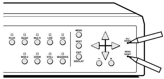
Using the ALL RESET button
Press this button to reset the following:
- Reset the time and date in the (CLOCK SET) menu to the default setting.
- The display mode on monitor 1 will return to 9 divisions split screen (default mode).
- The display mode on monitor 2 will return to sequential screen (default mode).
- The information about the alarms displayed in the (ALARM DATA) menu will be erased.
NOTE: If the unit does not function properly, press the ALL RESET button.
Please note that all the settings mentioned above will be reset.
Using the MENU RESET Button
A: While a menu is displayed, press the MENU RESET button to reset all the values of the displayed menu to the default values.
B: If no menu is displayed, press the MENU RESET button to reset the time to the nearest hour.
NOTE: For example, between 10:30:00 and 11:29:59 the clock will be reset to 11:00:00.
■ Clock, title display operations
Even if the clock and title displays are turned off in the (DISPLAY SET) menu, the display mode can be selected as indicated below by pressing the EXIT/DISPLAY button. Also, when the clock is displayed, it's position can be changed by pressing the ▲ (or ▼) button.
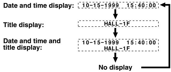
flowchart
graph TD
    A["Date and time display: 10-15-1999 15:40:00"] --> B["Title display: HALL-1F"]
    B --> C["Date and time and title display: 10-15-1999 15:40:00 HALL-1F"]
    C --> D["No display"]

Press the LIVE button.
The live pictures from the cameras connected to the CAMERA IN terminals on the unit back panel will be displayed on monitor 1.
Refer to the diagrams below for the buttons to press in order to select the desired operation mode.
The video signal is output at the VCR OUT terminal on the back panel, for recording purposes.
Please refer to (VCR SET) for more information (see page 29).
Live picture mode operations steps on monitor 1
• Full screen operations (see page 12)
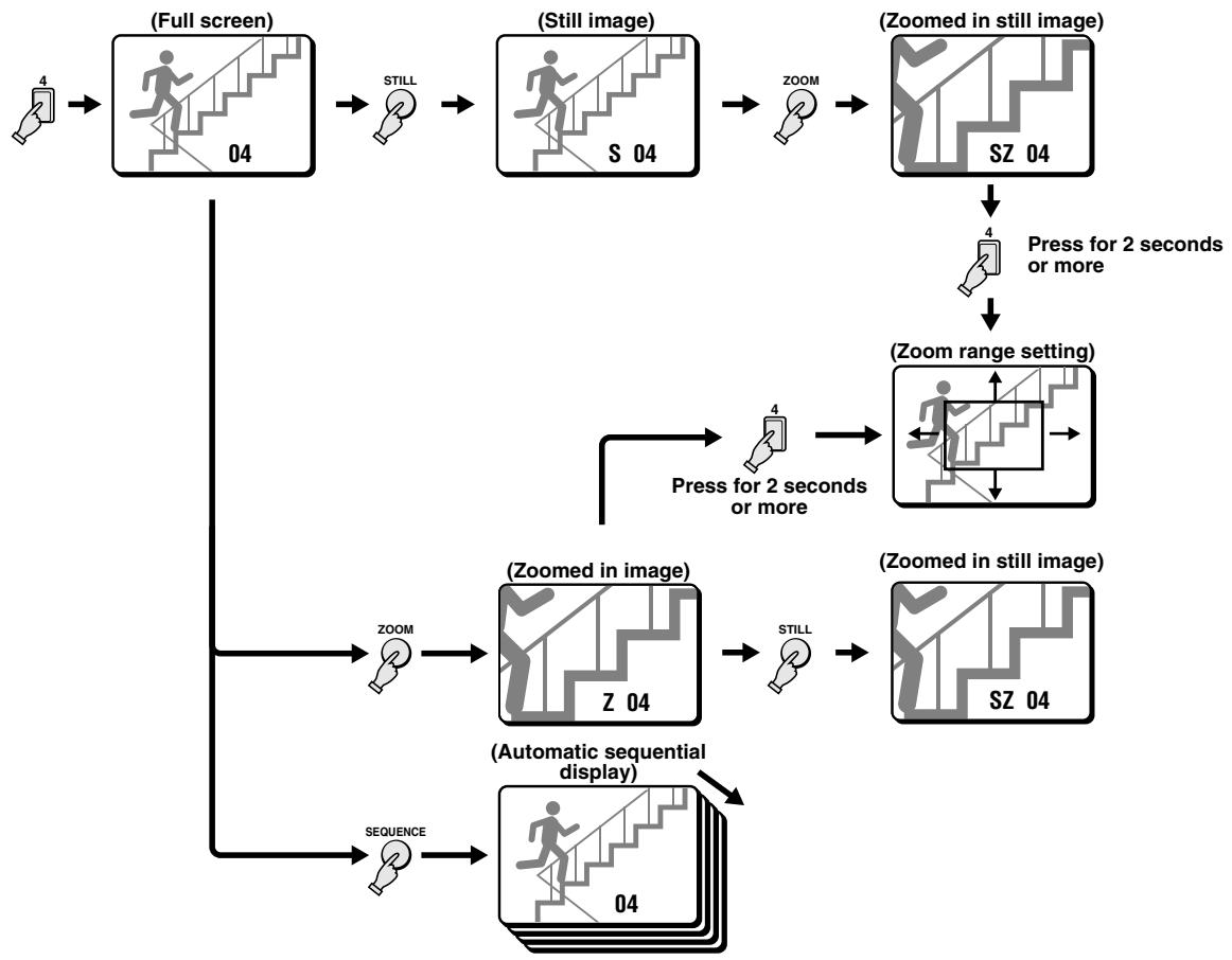
flowchart
graph TD
    A["4"] --> B["(Full screen)"]
    B --> C["04"]
    C --> D["Still"]
    D --> E["S 04"]
    E --> F["ZOOM"]
    F --> G["(Zoomed in still image)"]
    G --> H["SZ 04"]
    H --> I["Press for 2 seconds or more"]
    I --> J["(Zoom range setting)"]
    J --> K["Press for 2 seconds or more"]
    K --> L["ZOOM"]
    L --> M["(Zoomed in image)"]
    M --> N["Z 04"]
    N --> O["Still"]
    O --> P["(Zoomed in still image)"]
    P --> Q["SZ 04"]
    Q --> R["(Automatic sequential display)"]
    R --> S["Sequence"]
    S --> T["04"]
- 4 divisions split screen operations (see page 14)
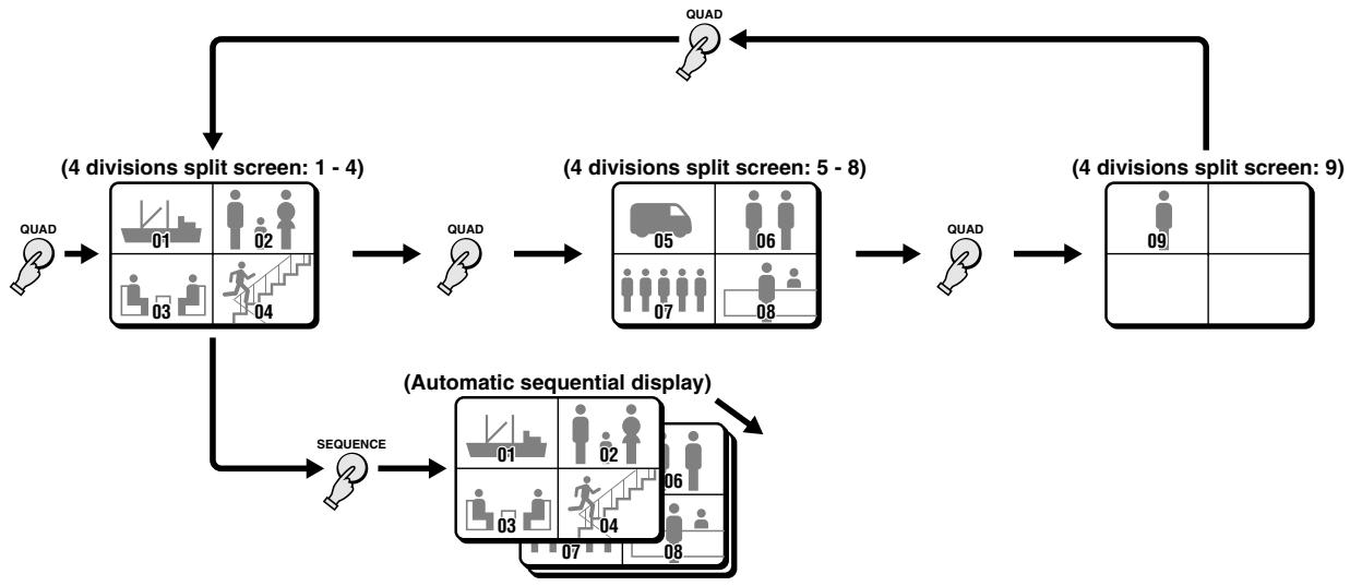
flowchart
graph TD
    A["QUAD"] --> B["(4 divisions split screen: 1 - 4)"]
    B --> C["QUAD"]
    C --> D["(4 divisions split screen: 5 - 8)"]
    D --> E["QUAD"]
    E --> F["(4 divisions split screen: 9)"]
    F --> G["(Automatic sequential display)"]
    G --> H["SEQUENCE"]
    H --> I["(Automatic sequential display)"]
LIVE PICTURE MODE
- Multi-display screen operations (see page 15)
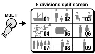
flowchart
graph TD
    A["MULTI"] --> B["Step 01: Group 01"]
    B --> C["Step 02: Group 02"]
    C --> D["Step 03: Group 03"]
    D --> E["Step 04: Group 04"]
    E --> F["Step 05: Group 05"]
    F --> G["Step 06: Group 06"]
    G --> H["Step 07: Group 07"]
    H --> I["Step 08: Group 08"]
    I --> J["Step 09: Group 09"]
- Plus-display screen operations (see page 15)
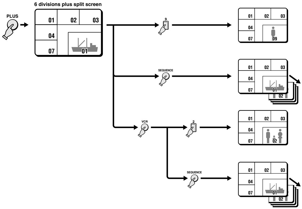
flowchart
graph TD
    A["PLUS"] --> B["6 divisions plus split screen"]
    B --> C["9"]
    B --> D["SEQUENCE"]
    B --> E["VCR"]
    B --> F["SEQUENCE"]
    C --> G["01 02 03"]
    D --> H["01 02 03"]
    E --> I["04 07 01"]
    F --> J["01 02 03"]
    G --> K["07 09"]
    H --> L["07 01"]
    I --> M["07 02"]
    J --> N["07 02"]
Live picture mode operations steps on monitor 2 (see page 17)
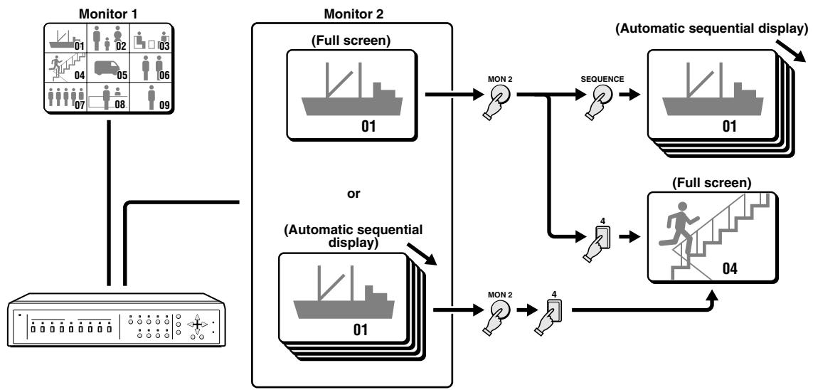
flowchart
graph TD
    A["Monitor 1"] --> B["Monitor 2"]
    B --> C["(Automatic sequential display)"]
    C --> D["(Automatic sequential display)"]
    D --> E["(Automatic sequential display)"]
    E --> F["(Automatic sequential display)"]
    F --> G["(Automatic sequential display)"]
    G --> H["(Automatic sequential display)"]
    H --> I["(Automatic sequential display)"]
    I --> J["(Automatic sequential display)"]
    J --> K["(Automatic sequential display)"]
    K --> L["(Automatic sequential display)"]
    L --> M["(Automatic sequential display)"]
    M --> N["(Automatic sequential display)"]
    N --> O["(Automatic sequential display)"]
    O --> P["(Automatic sequential display)"]
    P --> Q["(Automatic sequential display)"]
    Q --> R["(Automatic sequential display)"]
    R --> S["(Automatic sequential display)"]
    S --> T["(Automatic sequential display)"]
    T --> U["(Automatic sequential display)"]
    U --> V["(Automatic sequential display)"]
    V --> W["(Automatic sequential display)"]
    W --> X["(Automatic sequential display)"]
    X --> Y["(Automatic sequential display)"]
    Y --> Z["(Automatic sequential display)"]
    Z --> A


flowchart
graph TD
    A["Group 02"] --> B["Group S 02"]
    C["Hand icon 2"] --> D["Still icon"]
flowchart
graph TD
    A["User icon 03"] --> B["User icon 03"]
    B --> C["Z Zoom"]
    style A fill:#f9f,stroke:#333
    style B fill:#bbf,stroke:#333
    style C fill:#dfd,stroke:#333
Press a SELECT (1 - 9) button.
The live pictures from the selected camera will be displayed full screen.
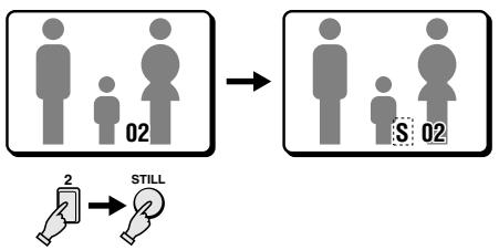
Example: To freeze the image from camera 2
1 Press the SELECT 2 button.
The camera 2 indicator lights, the image from camera 2 is displayed full screen.
2 Press the STILL button.
The STILL indicator flashes and "S" flashes on-screen.
NOTE: When a still image is displayed, press the ZOOM button for a zoomed in still image. To return to normal still image display, press the ZOOM button one more time.
To cancel the still image display mode
Press the STILL button.
If another mode button is pressed, the still image display mode is cancelled and the selected mode starts.
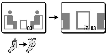
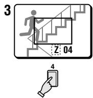
Example: To zoom in the image from camera 3
1 Press the SELECT 3 button.
The camera 3 indicator lights, the image from camera 3 is displayed full screen.
2 Press the ZOOM button.
The ZOOM indicator flashes and "Z" flashes on-screen.
NOTE: The zoomed in area will be as set by the zoom range frame.
To cancel the zoomed in image display mode
Press the ZOOM button.
If another mode button is pressed, the selected mode starts.
flowchart
graph TD
    A["User 02"] --> B["Z: 02"]
    B --> C["SZ: 02"]
    A --> D["Zoom"]
    D --> E["Still"]
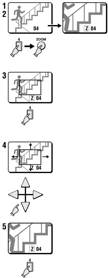
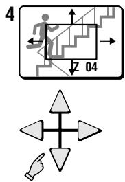
Example: To zoom in the image from camera 4 and set the zoom range
You can select the portion of the image to zoom in. The default zoomed in area is the centre of the image, but if a different zoom range is selected it will be memorized until changed or cancelled.
1 Press the SELECT 4 button.
The camera 4 indicator lights, the image from camera 4 is displayed full screen.
2 Press the ZOOM button.
The ZOOM indicator flashes and "Z" flashes on-screen.
3 Press the SELECT 4 button for about 2 seconds.
The zoomed in image will switch to the normal display mode, and the zoom range frame is displayed.
NOTE: If the zoom range frame is not moved for about 10 seconds, the display will automatically return to zoomed in mode.
To display the zoom range frame again, press the SELECT 4 button for about 2 seconds.
4 Press the ▲, ▼, ◀ or ▶ button repeatedly to move the zoom range frame to the desired area of the image.
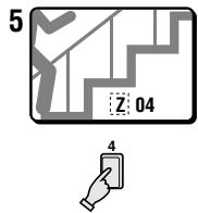
5 Press the SELECT 4 button.
The area selected by the zoom range frame is now zoomed in. If necessary, follow the same procedure to set the zoom range for the other cameras.
To cancel the zoomed in image display mode
Press the ZOOM button.
If another mode button is pressed, the selected mode starts.
While in zoomed mode, if the SELECT button is pressed one more time, depending on the movement of the subject, the image may be more or less clear. Pressing the SELECT button repeatedly will produce the following according to the image conditions.
- Image with little or no movement (close to a still image)
The image of still objects will be clear, the picture quality of moving areas of the image will be coarse.
- Image with normal movement (people or vehicles)
The moving objects in the image will be clear, the picture quality of areas of the image with little movement will be coarse.
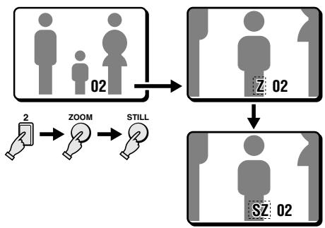
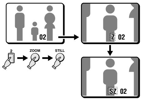
Example: To freeze the zoomed in image from camera 2
1 Press the SELECT 2 button.
The camera 2 indicator lights, the image from camera 2 is displayed full screen.
2 Press the ZOOM button.
The image from camera 2 is zoomed in, and "Z" flashes on-screen.
3 Press the STILL button.
The STILL indicator flashes and the ZOOM indicator lights. The camera 2 zoomed in image is frozen, and "SZ" flashes on-screen.
To cancel the still and zoomed in image display modes
Press the STILL button, then press the ZOOM button.
If another mode button is pressed, the selected mode starts.
flowchart
graph LR
    A["01"] --> B["01"]
    style A fill:#f9f,stroke:#333
    style B fill:#bbf,stroke:#333
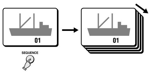
Automatic sequential full screen display
Press the SEQUENCE button.
The SEQUENCE indicator flashes. The pictures from each camera are displayed sequentially full screen, on monitor 1, according to the monitor 1 sequential mode and speed set in the (MONITOR SET) menu (see page 35). The camera SELECT indicators (1 – 9) light sequentially according to the displayed camera.
To cancel the sequential display mode
Press the SEQUENCE button or the SELECT button.
4 DIVISIONS SPLIT SCREEN OPERATIONS
Live picture mode

flowchart
graph TD
    A["01: Boat Activity"] --> B["02: Human Activity"]
    B --> C["03: Bus Activity"]
    C --> D["04: Walkup/Group Step"]
    D --> E["05: Truck Delivery"]
    E --> F["06: Group Distribution"]
    F --> G["07: Student Group Distribution"]
    G --> H["08: Student Group Distribution"]
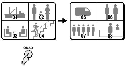
    I["QUAD"] --> J["Arrow pointing to the diagram"]
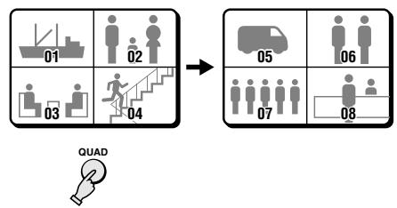
Press the QUAD button.
The 4 divisions split screen display mode will be selected.
Switching the 4 divisions split screen
Press the QUAD button.
Every time the QUAD button is pressed a 4 divisions split screen (1 - 4, 5 - 8, 9) is selected. The camera SELECT indicators light according to the displayed cameras.
flowchart
graph TD
    A["01 Task Setup"] --> B["02 Step 1"]
    B --> C["03 Step 2"]
    C --> D["04 Step 3"]
    D --> E["05 Step 4"]
    E --> F["06 Step 5"]
    F --> G["07 Step 6"]
    G --> H["08 Step 7"]
    H --> I["Final Output"]
    style A fill:#f9f,stroke:#333
    style B fill:#f9f,stroke:#333
    style C fill:#f9f,stroke:#333
    style D fill:#f9f,stroke:#333
    style E fill:#f9f,stroke:#333
    style F fill:#f9f,stroke:#333
    style G fill:#f9f,stroke:#333
    style H fill:#f9f,stroke:#333
    style I fill:#f9f,stroke:#333
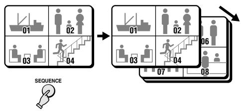
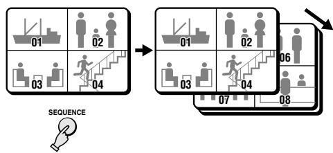
Automatic sequential 4 divisions split screen display
Press the SEQUENCE button.
The SEQUENCE indicator flashes. The 4 divisions split screens are displayed sequentially according to the 4 divisions split screen sequential mode and speed set in the (MONITOR SET) menu (see page 35). The camera SELECT indicators (1 - 4, 5 - 8, 9) light sequentially according to the displayed 4 divisions split screen.
To cancel the sequential display mode
Press the SEQUENCE button or the SELECT button.
MULTI-DISPLAY SCREEN OPERATIONS
Live picture mode


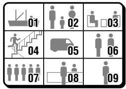
Press the MULTI button.
The 9 divisions split screen display mode will be selected.
NOTE: The display position of each camera within the 9 divisions split screens can be set as desired (see page 43).
The PLUS indicator flashes. The 6 divisions plus screen display mode will be selected. (The plus-display will appear in the bottom right corner of the screen.)
flowchart
graph TD
    A["01"] --> B["02"]
    B --> C["03"]
    D["04"] --> E["07"]
    E --> F["01"]
    F --> G["09"]
    H["9"] --> I["手机图标"]
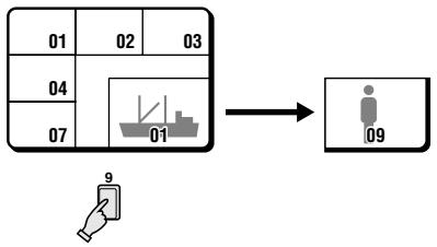
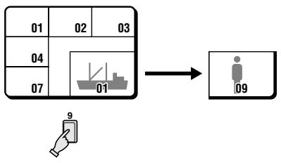
Example: To display the image from camera 9 in the plus screen area
Press the SELECT 9 button.
The camera 9 indicator lights, the image from camera 9 is displayed in the plus screen area.
To cancel the plus display mode
Press the PLUS button.
flowchart
graph TD
    A["01"] --> B["02"]
    B --> C["03"]
    D["04"] --> E["01"]
    F["07"] --> G["01"]
    H["SEQUENCE"] --> I["01"]
    I --> J["02"]
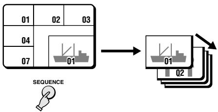
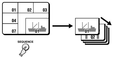
Automatic sequential plus display
Press the SEQUENCE button.
The SEQUENCE indicator flashes. The pictures from each camera are displayed sequentially in the plus screen area, on monitor 1, according to the monitor 1 sequential mode and speed set in the (MONITOR SET) menu (see page 35). The camera SELECT indicators (1 – 9) light sequentially according to the displayed camera.
To cancel the sequential display mode
Press the SEQUENCE button.
flowchart
graph TD
    A["01"] --> B["02"]
    B --> C["03"]
    D["04"] --> E["01"]
    F["07"] --> E
    E --> G["→"]
    H["VCR"] --> I["2"]
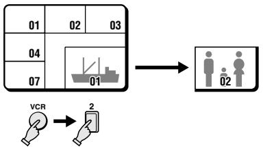
Example: To display the recorded image from camera 2 in the plus screen area
1 Press the VCR button.
The VCR indicator flashes and, the VCR tape playback image is displayed in the plus screen area.
2 Press the SELECT 2 button.
The camera 2 indicator lights, the image from camera 2 is displayed in the plus screen area.
flowchart
graph TD
    A["01"] --> B["02"]
    B --> C["03"]
    D["04"] --> E["01"]
    F["07"] --> G["01"]
    H["VCR"] --> I["SEQUENCE"]
    J["02"] --> K["Output Box 01"]
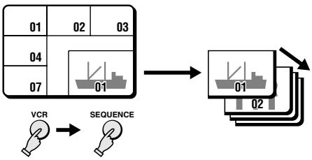
Automatic sequential plus display of recorded pictures
1 Press the VCR button.
The VCR indicator flashes and the VCR tape playback image is displayed in the plus screen area.
2 Press the SEQUENCE button.
The SEQUENCE indicator flashes, and the recorded pictures are displayed sequentially in the plus screen area, on monitor 1, according to the monitor 1 sequential mode and speed set in the (MONITOR SET) menu (see page 35). The camera SELECT indicators (1 – 9) light sequentially according to the displayed camera.
To cancel the automatic sequential plus display
- To cancel the sequential display mode, press the SEQUENCE button.
- To cancel the plus display mode, press the PLUS button.
MONITOR 2 OPERATIONS
Live pictures will be displayed on monitor 2 even during VCR playback mode
Live picture mode

flowchart
graph TD
    A["Monitor 1"] --> B["Monitor 2"]
    B --> C["Monitor 2"]
    C --> D["Monitor 2"]
    D --> E["Monitor 2"]
    style A fill:#f9f,stroke:#333
    style B fill:#ccf,stroke:#333
    style C fill:#cfc,stroke:#333
    style D fill:#fcc,stroke:#333
flowchart
graph TD
    A["Monitor 1"] --> B["Device"]
    C["Monitor 2"] --> D["Sequence"]
    D --> E["Monitor 2"]
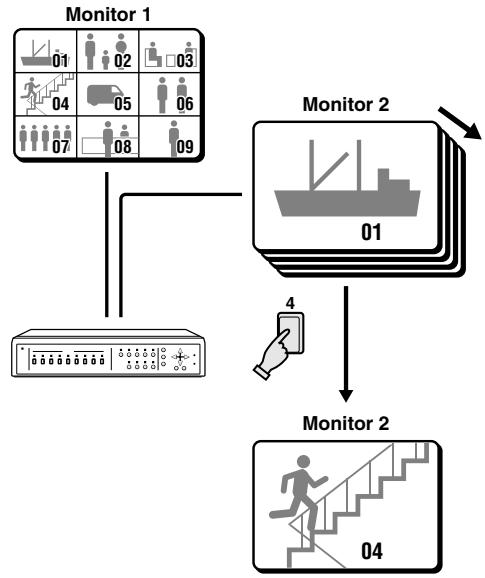
Press the MON 2 button.
The MON 2 indicator will flash, and the live pictures display mode on monitor 2 can be set. The available display modes are full screen or full screen automatic sequential display.
Example: To display full screen the image from camera 4 on monitor 2
Press the SELECT 4 button.
The camera 4 indicator lights, the image from camera 4 is displayed full screen.
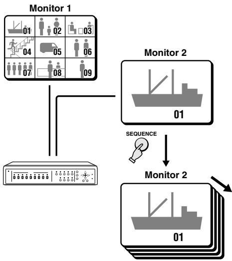
To switch the display mode on monitor 2 from full screen to full screen automatic sequential display
Press the SEQUENCE button.
The SEQUENCE indicator flashes and the pictures from each camera are displayed sequentially full screen, on monitor 2, according to the monitor 2 sequential mode and speed set in the (MONITOR SET) menu (see page 35).
To cancel the sequential display mode and the monitor 2 display settings Press the SEQUENCE button, then press the MON 2 button.
■ TO DISPLAY ON MONITOR 2 THE SAME IMAGE AS ON MONITOR 1
Press the MON 2 button.
This function can be used to monitor the images from a second location. In the (MONITOR SET) menu, set the item “MON2 ← MON1” to “ON” (see page 35).
NOTE: When this setting is used, the MON 2 button will not be operate.

Press the VCR button.
The VCR playback display mode is selected. When a tape is played back, the recording of the live pictures will be displayed on monitor 1.
During VCR playback mode, if a second VCR is connected to the VCR OUT terminal, live pictures can be recorded.
VCR playback mode operations steps on monitor 1
• Full screen operations (see page 20)
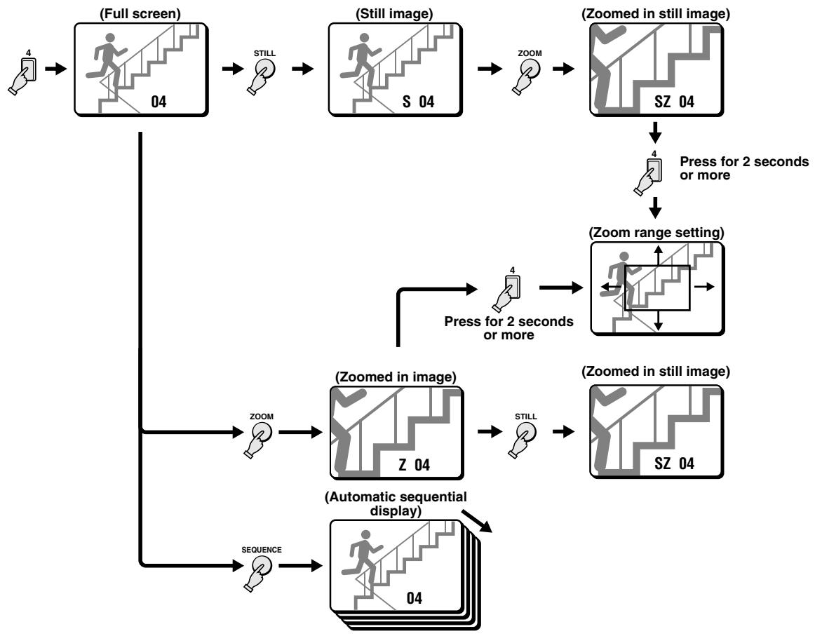
flowchart
graph TD
    A["4"] --> B["(Full screen)"]
    B --> C["04"]
    C --> D["Still"]
    D --> E["S 04"]
    E --> F["ZOOM"]
    F --> G["(Zoomed in still image)"]
    G --> H["SZ 04"]
    H --> I["Press for 2 seconds or more"]
    I --> J["(Zoom range setting)"]
    J --> K["Press for 2 seconds or more"]
    K --> L["ZOOM"]
    L --> M["(Zoomed in image)"]
    M --> N["Z 04"]
    N --> O["Still"]
    O --> P["(Zoomed in still image)"]
    P --> Q["SZ 04"]
    Q --> R["(Automatic sequential display)"]
    R --> S["04"]
    S --> T["SEQUENCE"]
- 4 divisions split screen operations (see page 22)
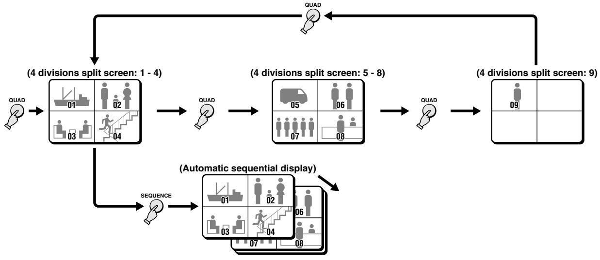
flowchart
graph TD
    A["QUAD"] --> B["(4 divisions split screen: 1 - 4)"]
    B --> C["QUAD"]
    C --> D["(4 divisions split screen: 5 - 8)"]
    D --> E["QUAD"]
    E --> F["(4 divisions split screen: 9)"]
    F --> G["(Automatic sequential display)"]
    G --> H["SEQUENCE"]
    H --> I["(Automatic sequential display)"]
- Multi-display screen operations (see page 23)
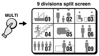
flowchart
graph TD
    A["MULTI"] --> B["9 divisions split screen"]
    B --> C["01: Down arrow, group icon; 02: Up arrow, group icon; 03: Down arrow, group icon; 04: Up stairs, group icon; 05: Down car, group icon; 06: Up person, group icon; 07: Down person, group icon; 08: Down person, group icon; 09: Up person, group icon"]
- Plus-display screen operations (see page 23)
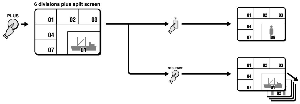
flowchart
graph TD
    A["PLUS"] --> B["6 divisions plus split screen"]
    B --> C["9"]
    B --> D["SEQUENCE"]
    C --> E["01 02 03"]
    C --> F["04"]
    C --> G["07"]
    D --> H["01 02 03"]
    D --> I["04"]
    D --> J["07"]
VCR playback mode operations steps on monitor 2 (see page 17)
When the VCR button is pressed, the recorded pictures are displayed on monitor 1 and live pictures will be displayed on monitor 2.
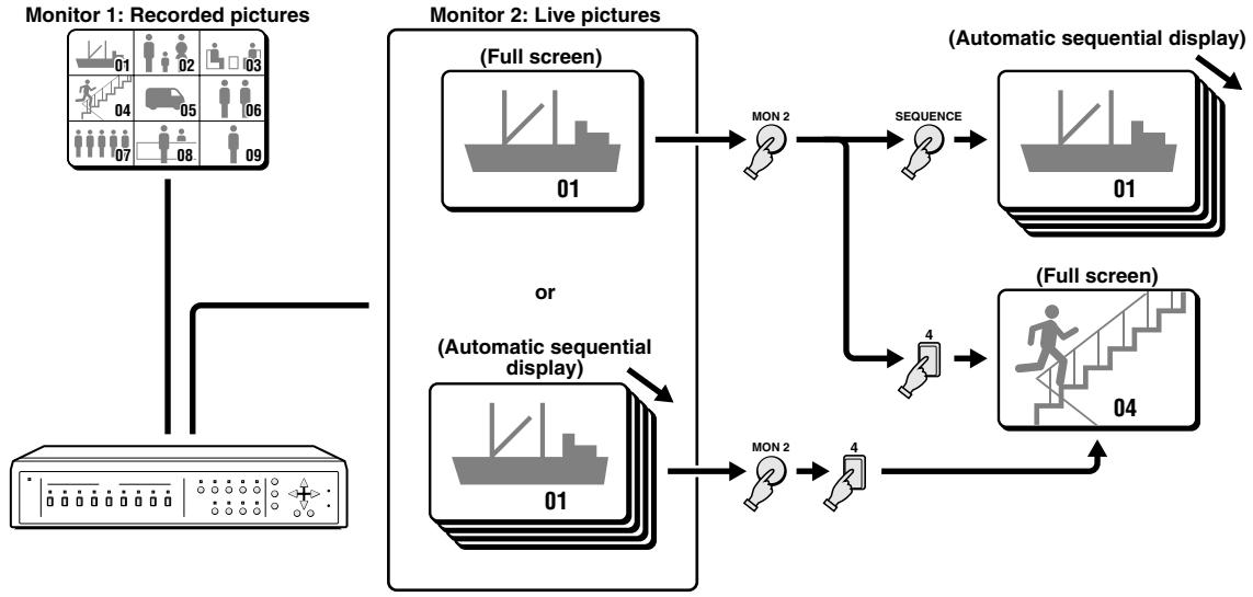
flowchart
graph TD
    A["Monitor 1: Recorded pictures"] --> B["Monitor 2: Live pictures"]
    B --> C["(Automatic sequential display)"]
    C --> D["(Automatic sequential display)"]
    D --> E["(Automatic sequential display)"]
    style A fill:#f9f,stroke:#333
    style B fill:#ccf,stroke:#333
    style C fill:#cfc,stroke:#333
    style D fill:#fcc,stroke:#333


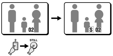
flowchart
graph TD
    A["Group 02"] --> B["Group S"]
    C["Hand icon 2"] --> D["Still icon"]
Press a SELECT (1 - 9) button.
The recorded pictures from the selected camera will be displayed full screen.
Example: To freeze the recorded image from camera 2
1 Press the SELECT 2 button.
The camera 2 indicator lights, the recorded image from camera 2 is displayed full screen.
2 Press the STILL button.
The STILL indicator flashes and "S" flashes on-screen.
NOTE: When a still image is displayed, press the ZOOM button for a zoomed in still image. To return to normal still image display, press the ZOOM button one more time.
To cancel the still image display mode
Press the STILL button.
If another mode button is pressed, the still image display mode is cancelled and the selected mode starts.
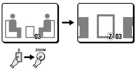
flowchart
graph TD
    A["User Group 03"] --> B["Target Object"]
    C["User Group 3"] --> D["ZOOM"]
    style A fill:#f9f,stroke:#333
    style B fill:#ccf,stroke:#333
    style C fill:#cfc,stroke:#333
    style D fill:#fcc,stroke:#333
Example: To zoom in the recorded image from camera 3
1 Press the SELECT 3 button.
The camera 3 indicator lights, the recorded image from camera 3 is displayed full screen.
2 Press the ZOOM button.
The ZOOM indicator flashes and "Z" flashes on-screen.
NOTE: The zoomed in area will be as set by the zoom range frame.
To cancel the zoomed in image display mode
Press the ZOOM button.
If another mode button is pressed, the selected mode starts.
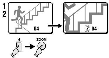
flowchart
graph TD
    A["Step 1: Step 04"] --> B["Step 2: Step 04"]
    B --> C["Zoom"]
    C --> D["Step 3: Step 04"]
    D --> E["Step 4: Step 04"]
    style A fill:#f9f,stroke:#333
    style B fill:#ccf,stroke:#333
    style C fill:#cfc,stroke:#333
    style D fill:#fcc,stroke:#333
    style E fill:#ffc,stroke:#333
flowchart
graph TD
    A["User 02"] --> B["Z:02"]
    B --> C["SZ:02"]
    D["User 02"] --> E["Z:02"]
    E --> F["SZ:02"]
    G["User 02"] --> H["Z:02"]
    H --> I["SZ:02"]
    J["User 02"] --> K["Z:02"]
    K --> L["SZ:02"]
    M["User 02"] --> N["Z:02"]
    N --> O["SZ:02"]
    P["User 02"] --> Q["Z:02"]
    Q --> R["SZ:02"]
    S["User 02"] --> T["Z:02"]
    T --> U["SZ:02"]
Example: To zoom in the recorded image from camera 4 and set the zoom range
You can select the portion of the image to zoom in. The default zoomed in area is the centre of the image, but if a different zoom range is selected it will be memorized until changed or cancelled.
1 Press the SELECT 4 button.
The camera 4 indicator lights, the recorded image from camera 4 is displayed full screen.
2 Press the ZOOM button.
The ZOOM indicator flashes and "Z" flashes on-screen.
3 Press the SELECT 4 button for about 2 seconds.
The zoomed in image will switch to the normal display mode, and the zoom range frame is displayed.
NOTE: If the zoom range frame is not moved for about 10 seconds, the display will automatically return to zoomed in mode.
To display the zoom range frame again, press the SELECT 4 button for about 2 seconds.
4 Press the ▲, ▼, ◀ or ▶ button repeatedly to move the zoom range frame to the desired area of the image.
5 Press the SELECT 4 button.
The area selected by the zoom range frame is now zoomed in. If necessary, follow the same procedure to set the zoom range for the other cameras.
To cancel the zoomed in image display mode
Press the ZOOM button.
If another mode button is pressed, the selected mode starts.
Example: To freeze the zoomed in recorded image from camera 2
1 Press the SELECT 2 button.
The camera 2 indicator lights, the recorded image from camera 2 is displayed full screen.
2 Press the ZOOM button.
The recorded image from camera 2 is zoomed in, and "Z" flashes on-screen.
3 Press the STILL button.
The STILL indicator flashes and the ZOOM indicator lights. The camera 2 zoomed in image is frozen, and "SZ" flashes on-screen.
To cancel the still and zoomed in image display modes
Press the STILL button, then press the ZOOM button.
If another mode button is pressed, the selected mode starts.
flowchart
graph LR
    A["01"] --> B["01"]
    style A fill:#f9f,stroke:#333
    style B fill:#bbf,stroke:#333
Automatic sequential full screen display
Press the SEQUENCE button.
The recorded pictures from each camera are displayed sequentially full screen, on monitor 1, according to the monitor 1 sequential mode and speed set in the (MONITOR SET) menu (see page 35). The camera SELECT indicators (1 – 9) light sequentially according to the displayed camera.
To cancel the sequential display mode
Press the SEQUENCE button one more time.
NOTE: If the sequential display speed set in the (MONITOR SET) menu is faster than the tape playback speed, the images will not be displayed correctly. The sequential screen display mode will be the same in 4 divisions split screen and in plus screen display modes.
4 DIVISIONS SPLIT SCREEN OPERATIONS
VCR playback mode

flowchart
graph TD
    A["01: Boat"] --> B["02: People"]
    B --> C["03: Bus"]
    C --> D["04: Walk up stairs"]
    D --> E["05: Truck"]
    E --> F["06: People"]
    F --> G["07: Group of people"]
    G --> H["08: Group of people"]
Press the QUAD button.
The recorded images 4 divisions split screen display mode is selected.
Switching the 4 divisions split screen
Press the QUAD button.
Every time the QUAD button is pressed a 4 divisions split screen (1 - 4, 5 - 8, 9) is selected. The camera SELECT indicators light according to the displayed cameras.
flowchart
graph TD
    A["01: Boat"] --> B["02: Person"]
    B --> C["03: Staircase"]
    C --> D["04: Walk up"]
    D --> E["05: Bus Icon"]
    E --> F["06: Step at 07"]
    F --> G["07: Walk up"]
    G --> H["08: Bus Icon"]
    style A fill:#f9f,stroke:#333
    style B fill:#f9f,stroke:#333
    style C fill:#f9f,stroke:#333
    style D fill:#f9f,stroke:#333
    style E fill:#f9f,stroke:#333
    style F fill:#f9f,stroke:#333
    style G fill:#f9f,stroke:#333
    style H fill:#f9f,stroke:#333
Automatic sequential 4 divisions split screen display
Press the SEQUENCE button.
The 4 divisions split screens are displayed sequentially according to the 4 divisions split screen sequential mode and speed set in the (MONITOR SET) menu (see page 35). The camera SELECT indicators (1 - 4, 5 - 8, 9) light sequentially according to the displayed 4 divisions split screen.
To cancel the sequential display mode
Press the SEQUENCE button one more time.
MULTI-DISPLAY SCREEN OPERATIONS
VCR playback mode

Press the MULTI button.
The recorded images 9 divisions split screen display mode will be selected.
NOTE: The display position of each camera within the 9 divisions split screens can be set as desired (see page 43).
The recorded images 6 divisions plus screen display mode will be selected. (The plus-display will appear in the bottom right corner of the screen.)
NOTE: During VCR playback mode, a live picture cannot be displayed in the plus screen area.
flowchart
graph TD
    A["01"] --> B["02"]
    B --> C["03"]
    D["04"] --> E["07"]
    E --> F["01"]
    F --> G["09"]
    H["9"] --> I["Hand icon"]
Example: To display the recorded image from camera 9 in the plus screen area
Press the SELECT 9 button.
The camera 9 indicator lights, the recorded image from camera 9 is displayed in the plus screen area.
To cancel the plus display mode Press the PLUS button.
flowchart
graph TD
    A["01"] --> B["02"]
    B --> C["03"]
    D["04"] --> E["01"]
    F["07"] --> G["01"]
    H["SEQUENCE"] --> I["02"]
Automatic sequential plus display
Press the SEQUENCE button.
The recorded pictures from each camera are displayed sequentially in the plus screen area, on monitor 1, according to the monitor 1 sequential mode and speed set in the (MONITOR SET) menu (see page 35). The camera SELECT indicators (1 – 9) light sequentially according to the displayed camera.
To cancel the sequential plus display
- To cancel the sequential display mode, press the SEQUENCE button.
- To cancel the plus display mode, press the PLUS button.
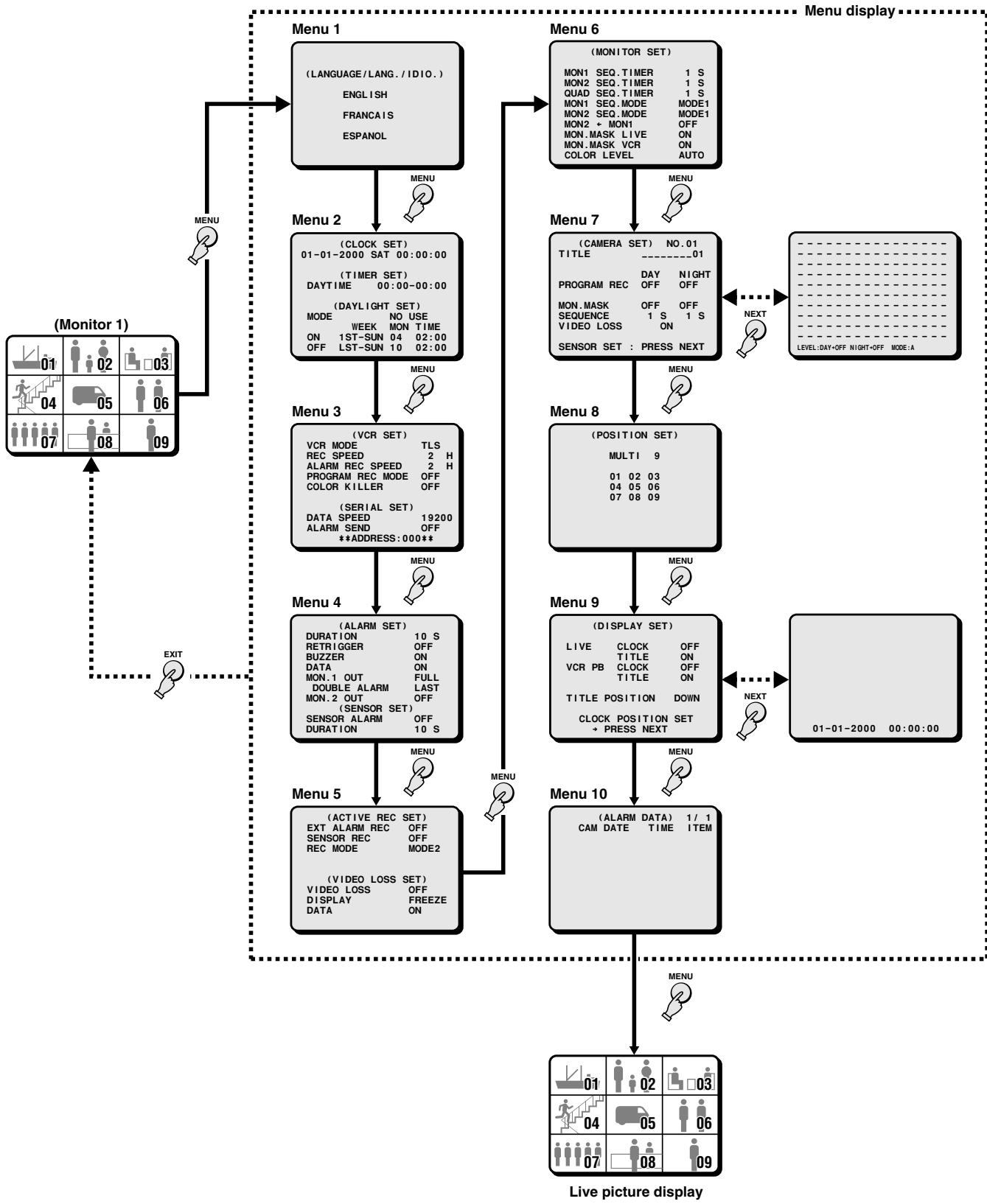
To display the menus, press the MENU button.
flowchart
Live picture display flowchart showing menu navigation from Monitor 1 to Live Picture Display via multiple functional modules including Monitator, Camera, Position, Display, and Media.(LANGUAGE/LANG./IDIO.)
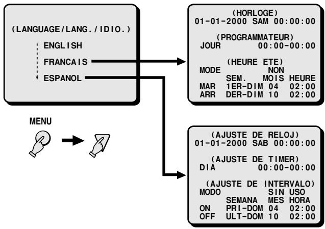
The default menu language is English. The available language settings are English, French and Spanish.
Setting the language
1 Press the MENU button once to display the (LANGUAGE/LANG./IDIO.) menu.
2 Press the ▼ button to highlight the desired language.
3 Press the MENU button to go to the next menu, or Press the EXIT button to exit the menu display and the selected language is set.
All the on-screen menus and settings will be displayed in the selected language.
flowchart
graph TD
    A["(LANGUAGE/LANG./IDIO.)"] --> B["(HORLOGE) 01-01-2000 SAM 00:00:00"]
    A --> C["(PROGRAMMATEUR) JOUR 00:00-00:00"]
    A --> D["(HEURE ETE) MODE SEM. MOIS HEURE MAR 1ER-DIM 04 02:00 ARR DER-DIM 10 02:00"]
    A --> E["(AJUSTE DE RELOJ) 01-01-2000 SAB 00:00:00"]
    A --> F["(AJUSTE DE TIMER) DIA 00:00-00:00"]
    A --> G["(AJUSTE DE INTERVALO) MODO SEMANA MES HORA ON PRI-DOM 04 02:00 OFF ULT-DOM 10 02:00"]
    H["MENU"] --> I["→"]
CLOCK AND DAYLIGHT SAVING SETTING
(CLOCK SET)
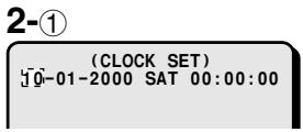
The default setting is as indicated below. The clock will start after the actual time and date are set and the operations under (TIMER SET) are completed.
Default clock settings: 01-01-2000 SAT 00:00:00 (January 1, 2000 at 00:00)
1 Press the MENU button twice to display the (CLOCK SET) menu.
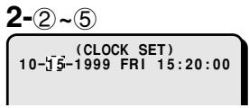
2 Example: Setting the clock to October 15, 1999 at 3:20 PM
① Press the + (or −) button to set the month (10), then press the ▶ button.
② Press the + (or −) button to set the day (15), then press the ▶ button.
③ Press the + (or −) button to set the year (1999), then press the ▶ button.
④ Press the + (or −) button to set the hours (15), then press the ▶ button.
⑤ Press the + (or −) button to set the minutes (20), then press the ▶ button.
NOTE: The day of the week (FRI) will be automatically set according to the date entered.
3 Press the ▼ button to go to (TIMER SET).
Press the MENU button to go to the next menu screen, or
Press the EXIT button to exit the menu display.


NOTE: To set the display mode for the clock, refer to "DISPLAY SET (CLOCK, TITLE)" on page 44.
(TIMER SET)
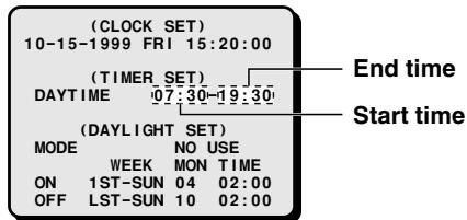
You can set a DAY and a NIGHT range for the 24 hour day period, in order to set each camera mode and programmed recording accordingly.
1 Set the daytime period start and end time.
2 Example: Day period from 7:30 AM to 7:30 PM Night period from 7:30 PM to 7:30 AM
① Using the + (or −) button, select (7) for the starting hour of the DAYTIME period, then press the ▶ button.
② Using the + (or −) button, select (30) for the starting minutes of the DAYTIME period, then press the ▶ button.
NOTE:
- The times for the day period only need to be set. The night period will be automatically set accordingly.
- If the day start and end time are the same, the DAYTIME settings will be active 24 hours a day.
3 Press the MENU button to go to the next menu screen, or
Press the EXIT button to exit the menu display.
3

(DAYLIGHT SET)
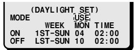
The default daylight saving time function setting is "NO USE", so the daylight adjustment will not be made.
If the unit will be used in an area where there is a daylight saving time change, set it to "USE", then if necessary, set when the daylight saving time is changed.
The default settings are:
Daylight saving time from the first Sunday of April, at 2:00 AM (1ST-SUN 04 02:00) to last Sunday of October, at 2:00 AM (LST-SUN 10 02:00).
■ TO MAKE CHANGES TO THE SETTINGS
1 Press the ▼ button to highlight the “NO USE” setting, then press the + (or −) button to select “USE”, and press the ▼ button one more time.
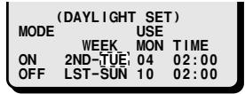
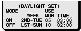
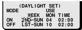
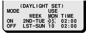
2 Example: Setting the daylight saving time from the second Tuesday of May at 3:00 AM, to the fourth Tuesday of September at 3:00 AM.
① Press the + (or −) button to set the WEEK (2ND), then press the ▶ button.
Menu: 1ST, 2ND, 3RD, 4TH or LST (first, second, third, fourth or last)
② Press the + (or −) button to set the WEEK (TUE), then press the ▶ button.
Menu: SUN, MON, TUE, WED, THU, FRI, SAT or SUN
③ Press the + (or −) button to set the MON (05), then press the ▶ button.
Menu: 1, 2, 3, 4 ..... 11, 12
(for January, February, March ..... December)
④ Press the + (or −) button to set the TIME (03), then press the ▼ button.
- Following the same procedure as above, set when the time is changed back from daylight saving time to standard time (the OFF settings).
3 Press the MENU button to go to the next menu screen, or
Press the EXIT button to exit the menu display.
1

2-②

2-④

2-①

2-③

VCR SETTING AND EXTERNAL CONTROL
COMMUNICATION SPEED SETTING
Menu 3
(VCR SET)
You must set this unit output to match the type (Timelapse or Real time VCR) and settings of the VCR used for recording.
■ Setting the VCR Output
1 Press the MENU button 3 times to display the (VCR SET) menu.
2 Using the + (or −) button, select the desired “VCR MODE” setting, then press the ▼ button.
Following this procedure, select the settings for REC SPEED, ALARM REC SPEED, PROGRAM REC MODE and COLOR KILLER.
3 Press the ▼ button to go to the (SERIAL SET) menu, or
Press the MENU button to go to the next menu screen, or
Press the EXIT button to exit the menu display.
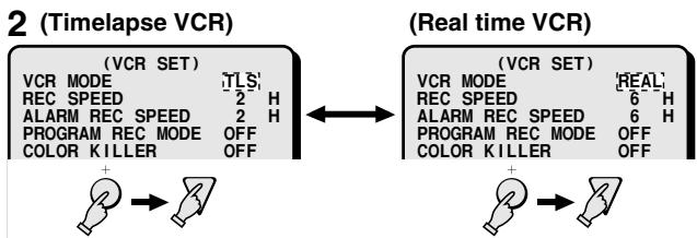
flowchart
graph LR
    A["2 (Timelapse VCR)"] --> B["(VCR SET)"]
    A --> C["VCR MODE"]
    A --> D["REC SPEED"]
    A --> E["ALARM REC SPEED"]
    A --> F["PROGRAM REC MODE"]
    A --> G["COLOR KILLER"]
    H["(Real time VCR)"] --> I["(VCR SET)"]
    H --> J["VCR MODE"]
    H --> K["REC SPEED"]
    H --> L["ALARM REC SPEED"]
    H --> M["PROGRAM REC MODE"]
    H --> N["COLOR KILLER"]
    O["+"] --> P["→"]
    Q["+"] --> R["→"]
VCR SET menu
If the VCR is not Equipped with a SW (switching) Output Connector
VCR MODE
TLS: If using a timelapse VCR. (Default setting)
REAL: If using a real time VCR.
REC SPEED
The recording speed settings on this unit correspond to recording durations on a T-120 tape.
With a timelapse VCR
Set the recording speed to match the recording speed of the timelapse VCR.
The available speeds are: 2 (2H) (Default setting), 12 (12H), 24 (24H), 48 (48H), 72 (72H), 96 (96H), 120, 168, 240, 360, 480, 720, 960 (960H)
With a real time VCR
Set the recording speed to match the recording speed of the real time VCR.
The available speeds are: 6 (6H) (Default setting), 18 (18H), 30 (30H), 48 (48H), 72 (72H), 96 (96H), 120, 168, 240, 360, 480, 720, 960 (960H)
NOTE: Real time VCRs speed is based on a T-160 cassette tape. When setting this unit to 6H, 18H or 30H, refer to the table 1 for the speed correspondence, and select the speed on the VCR accordingly.
Table 1
| REC SPEED setting | Recording speed setting on the real time VCR |
| 6 (6H) | 8H (8-hour mode) |
| 18 (18H) | 24H (24-hour mode) |
| 30 (30H) | 40H (40-hour mode) |
ALARM REC SPEED
With a timelapse VCR
Set the recording speed to use when an alarm trigger is received to match the alarm recording speed of the timelapse VCR.
The available speeds are:
2 (2H) (Default setting), 12 (12H), 24 (24H), NC, F2
NC: When an alarm trigger is received, the recording speed is not changed and stays as set under "REC SPEED".
F2: Use this setting when using the SW output terminal on a timelapse VCR that does not output a switching signal in 2H mode.
With a real time VCR
Set the recording speed to use when an alarm trigger is received to match the alarm recording speed of the real time VCR.
The available speeds are:
6 (6H) (Default setting), 18 (18H), NC, F6
NC: When an alarm trigger is received, the recording speed is not changed and stays as set under "REC SPEED".
F6: Use this setting when using the SW output terminal on a real time VCR that does not output a switching signal in 6H mode.
PROGRAM REC MODE (Default setting: OFF)
Using the programmed recording mode you can decide to only output the recorded live pictures from a certain camera or to give priority to the pictures from a certain camera.
This will set the programmed recording mode.
MODE1: Only the live pictures from the camera for which programmed recording is set are recorded.
MODE2: The live pictures from the camera for which programmed recording is set are recorded together with the live pictures from the other cameras.
OFF: Programmed recording will not be done.
NOTE:
- Programmed recording of multiple cameras is done by switching to each camera in order.
- In the (CAMERA SET) menu, set for each camera if programmed recording is to be conducted or not (see page 36).
- The recording mode set here is the same as the ACTIVE REC recording mode (see page 34). The programmed recording mode is the normal recording mode applied to the camera, while the active recording mode will modify the recording mode for the camera when an external alarm or a video sensor trigger is received.
- Any camera for which programmed recording is turned off, will not be recorded when an external alarm or a video sensor trigger is received. To record from a camera for which programmed recording is turned off, when an external alarm or a video sensor trigger is received, set the active recording mode to on.
COLOR KILLER (Default setting: OFF)
Used to playback a tape recorded through a black and white multiplexer, using a color multiplexer.
ON: When using a black and white tape, the color killer function is active.
OFF: The color killer function is not active.
NOTE: Model MPX-MD92 does not have COLOR KILLER.
VCR SETTING AND EXTERNAL CONTROL COMMUNICATION
SPEED SETTING
If the VCR is Equipped with a SW (switching) Output Connector (using the VCR switching signal)
Make the connection from this unit to the VCR SW output connector. The video signal output by this unit will be automatically switched to the recording speed according to the switching signal output by the VCR (switching pulse setting on the VCR).
The (VCR SET) menu “REC SPEED” and “ALARM REC SPEED” items do not need to be set.
If a switching signal is not output at the switching terminal
Some VCR models may not output a switching signal in 2H or 6H mode. In such a case, make the settings as indicated in the table below.
| VCR SET menu settings | Timelapse VCR | Real time VCR |
| REC SPEED | 2 (2H) | 6 (6H) |
| ALARM REC SPEED | F2 | F6 |
NOTE: When the recording speed is set to F2 or F6, the alarm recording speed is fixed to 2H or 6H. Therefore, when using a recording speed other than 2H or 6H, do not use the F2 or F6 setting.
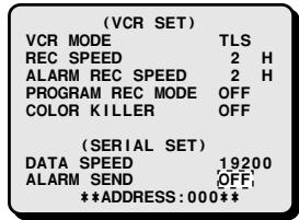
(SERIAL SET)
Connect the multiplexer to a computer, using a 9-pin D-SUB cable (sold separately), then set the maximum communication speed between the unit and the computer.
For detailed information, please refer to "INTERFACE SPECIFICATIONS" on page 48.
Setting the RS232C/RS485 communication
1 Press the ▼ button to highlight the setting to modify.
2 Using the + (or −) button, select the desired “DATA SPEED” setting, then press the ▼ button.
3 Using the + (or −) button, select the desired “ALARM SEND” setting.
4 Press the MENU button to go to the next menu screen, or
Press the EXIT button to exit the menu display.
2
![(VCR SET) VCR MODE TLS REC SPEED 2 H ALARM REC SPEED 2 H PROGRAM REC MODE OFF COLOR KILLER OFF (SERIAL SET) DATA SPEED [19200] ALARM SEND OFF **ADDRESS: 000**](/content/2024/12/96752/images/a655b853d118077339bd65ecb16deed851f4b376743be0a8cad66c370de59ad6.jpg)
3

SERIAL SET menu
DATA SPEED (Default setting: 19200 bps)
The available settings are: 2400, 4800, 9600, 19200 bps
ALARM SEND (Default setting: OFF)
ON: The alarm information is output at the RS232C/RS485 terminals.
OFF: The alarm information is not output at the RS232C/RS485 terminals.
Unit address confirmation
If multiple units are going to be controlled through a system controller (sold separately) via the RS485 connection, each unit must have a address for remote control purposes. The address set for the unit can be checked by accessing the (VCR SET) menu.
1 Press the MENU button three times to display the (VCR SET) menu.
The unit address is displayed on the last line of the menu. The unit address can be set using the Interface setting DIP switches on the back panel of the unit. (see page 49)
2 Press the MENU button to go to the next menu screen, or
Press the EXIT button to exit the menu display.
1
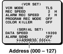
(Interface setting DIP switches)
(ALARM SET)
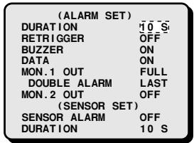
When an alarm trigger is received from sensors such as a door bell, movement sensor, etc. you can set the display mode and the recording mode for the pictures from the concerned camera. Using the (SENSOR SET) settings (see page 32), the triggers received from the video sensors can be set to operate as alarm triggers.
Changing the Settings
1 Press the MENU button 4 times to display the (ALARM SET) menu.
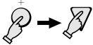
2 Using the + (or −) button, select the desired setting, then press the ▼ button.
- Repeat step 2, until all the settings are as desired.
3 Press the ▼ button to go to the (SENSOR SET) menu, or
Press the MENU button to go to the next menu screen, or
Press the EXIT button to exit the menu display.
2
ALARM SET menu
DURATION (Default setting: 10 S)
The available durations are (seconds):
1, 2, 3, 4, 5, 10, 20 (in 10 seconds increments)... 180, CC, NC, INDIV., OFF
CC: The alarm will go on as long as the alarm signal is received (minimum 1 second).
NC: The alarm will continue until reset.
INDIV.: The alarm duration will be as set for each of the cameras.
OFF: No alarm duration setting.
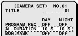
NOTE: If the "INDIV." setting is used, in the (CAMERA SET) menu, enter the desired alarm duration for each camera (see page 38).
RETRIGGER (Default setting: OFF)
To set if an alarm is received while the unit is already in alarm mode.
ON: During alarm mode, other alarm triggers will be received and the alarm duration will be extended.
OFF: The unit will not receive another alarm, while one is already being received.
BUZZER (Default setting: ON)
ON: A buzzer will be heard when an alarm trigger is received.
OFF: The buzzer will not be heard.
DATA (Default setting: OFF)
ON: The alarm data is recorded.
OFF: The alarm data is not recorded.
MON.1 OUT
(A)
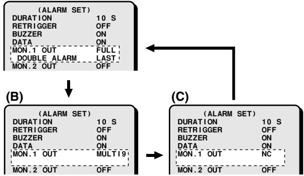
flowchart
graph TD
    subgraph (B)
        A["ALARM SET"] --> B["DURATION 10 S"]
        A --> C["RETRIGGER OFF"]
        A --> D["BUZZER ON"]
        A --> E["DATA ON"]
        A --> F["MON.1 OUT FULL"]
        A --> G["DOUBLE ALARM LAST"]
        A --> H["MON.2 OUT OFF"]
    end
    subgraph (C)
        I["ALARM SET"] --> J["DURATION 10 S"]
        I --> K["RETRIGGER OFF"]
        I --> L["BUZZER ON"]
        I --> M["DATA ON"]
        I --> N["MON.1 OUT NC"]
        I --> O["MON.2 OUT OFF"]
    end
(A) FULL (Default setting):
If an alarm trigger is received, the picture from the camera corresponding to the alarm input will be displayed full screen.
- DOUBLE ALARM (Default setting: LAST)
When using the "FULL" setting at the "MON.1 OUT" line, the following settings are possible.
LAST: When triggers from multiple cameras are received in full screen mode, the picture from the camera of the last alarm received is displayed.
FIRST: When triggers from multiple cameras are received in full screen mode, the picture from the camera of the first alarm received only is displayed. Camera pictures from subsequent alarm triggers will not be displayed.
SWITCH: When triggers from multiple cameras are received in full screen mode, the picture from each concerned camera will be displayed sequentially at 1 second interval.
(B) MULTI9: When an alarm trigger is received, the display will switch to a 9 divisions screen.
(C) NC: The display mode will remain unchanged when an alarm trigger is received.
MON.2 OUT (Default setting: OFF)
ON: Monitor 2 display will switch to full screen alarm display, when an alarm trigger is received.
OFF: Monitor 2 display will not change.
(SENSOR SET)
When the internal video sensor detects a movement in the live video signal, it can be set to trigger an alarm. Priority recording of the concerned pictures can also be set (ACTIVE REC).
Setting the SENSOR SET Mode
1 Press the ▼ button to highlight the setting to modify.
2 Using the + (or −) button, select the desired “SENSOR ALARM” setting, then press the ▼ button.
Following this procedure, select the settings for "DURATION".
3 Press the MENU button to go to the next menu screen, or
Press the EXIT button to exit the menu display.
2
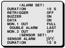

SENSOR SET menu
SENSOR ALARM (Default setting: OFF)
This will set if the internal video sensor triggers are considered as alarm triggers.
ON: The sensor triggers will be considered as alarms, and when received the display will switch to the selected alarm display mode and the buzzer will be heard.
OFF: The sensor triggers are not considered as alarms.
AND: Only when a sensor trigger and an alarm trigger are received simultaneously, it will be considered as an alarm.
NOTE: If SENSOR ALARM is set to AND, a trigger to an ALARM IN terminal alone will not be considered as an alarm.
DURATION (Default setting: 10 S)
When a video sensor detects a movement, this will set the active recording mode duration (see page 33).
The available durations are:
1, 2, 3, 4, 5, 10, 20 (in 10 seconds increments)... 180
NOTE: When the SENSOR ALARM settings "ON" and "AND" are used, the internal video sensor can trigger an alarm operation. The alarm duration is set by the "DURATION" setting in (ALARM SET) (see page 31).
ACTIVE RECORDING AND VIDEO LOSS
SETTING
(ACTIVE REC SET)
To set the priority recording mode when an external alarm or video sensor trigger is received.
Setting the ACTIVE REC Recording Mode
1 Press the MENU button 5 times to display the (ACTIVE REC SET) menu.
2 Using the + (or −) button select the desired “EXT ALARM REC” setting, then press the ▼ button.
All the other settings are selected using the same procedure.
3 Press the ▼ button to go to the (VIDEO LOSS SET) menu, or
Press the MENU button to go to the next menu screen, or
Press the EXIT button to exit the menu display.
2
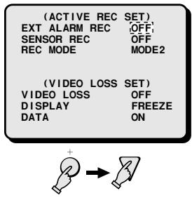
ACTIVE REC SET menu
EXT ALARM REC (Default setting: OFF)
ON: When an external alarm trigger is received, active recording is initiated, the concerned camera pictures being recorded in priority.
OFF: When an external alarm trigger is received, active recording will not be initiated.
SENSOR REC (Default setting: OFF)
ON: When a video sensor trigger is received, active recording is initiated, the concerned camera pictures being recorded in priority.
OFF: When a video sensor trigger is received, active recording will not be initiated.
REC MODE (Default setting: MODE2)
This setting selects the active recording operations.
MODE1: The live pictures from the camera corresponding to the alarm trigger only are recorded.
MODE2: The live pictures from the camera corresponding to the alarm trigger is recorded together with the signal from the other cameras.
Please refer to "ACTIVE REC Settings Examples" on page 34.
NOTE: Programmed recording function will select the camera to record or the camera priority recording normal mode, but the active recording mode will modify the recording mode for that camera when an external alarm or a video sensor trigger is received.
(VIDEO LOSS SET)
When the live picture signal feed is interrupted, you can set the action taken (frozen picture or color bars), and if the video loss is recorded as alarm data.
Setting the Video Loss Mode
1 Press the ▼ button to highlight the "VIDEO LOSS" setting.
2 Using the + (or −) button select the desired “VIDEO LOSS” setting, then press the ▼ button.
All the other settings are selected using the same procedure.
3 Press the MENU button to go to the next menu screen, or Press the EXIT button to exit the menu display.
3
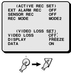
VIDEO LOSS SET menu
VIDEO LOSS (Default setting: OFF)
You can set the action to take when there is an interruption in the video signal feed.
OFF: The video loss will not be active independently of the setting entered for each camera.
INDIV.: The ON/OFF setting will be as set for each of the cameras.
NOTE: If the "INDIV." setting is used, in the (CAMERA SET) menu, enter the desired setting for each camera (see page 36).
DISPLAY (Default setting: FREEZE)
FREEZE: When there is a video loss, the image just previous to the interruption is frozen on-screen.
TEST: When there is a video loss, color bars are displayed on-screen.
NOTE: • Depending on the timing of the video loss, a complete picture may not be displayed.
- Even if a frozen image is selected for the monitor display, color bars only can be recorded.
DATA (Default setting: ON)
ON: The video losses data is recorded as alarm data.
OFF: The video losses data is not recorded.
NOTE: If the "ON" setting is used, you can review the video losses data (camera number, date, time) in the (ALARM DATA) menu (see page 45).
ACTIVE REC Settings Examples
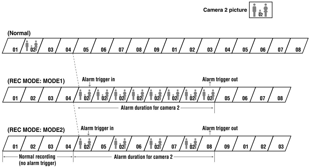
Example 1: Recording on the tape when an alarm trigger is received from camera 2
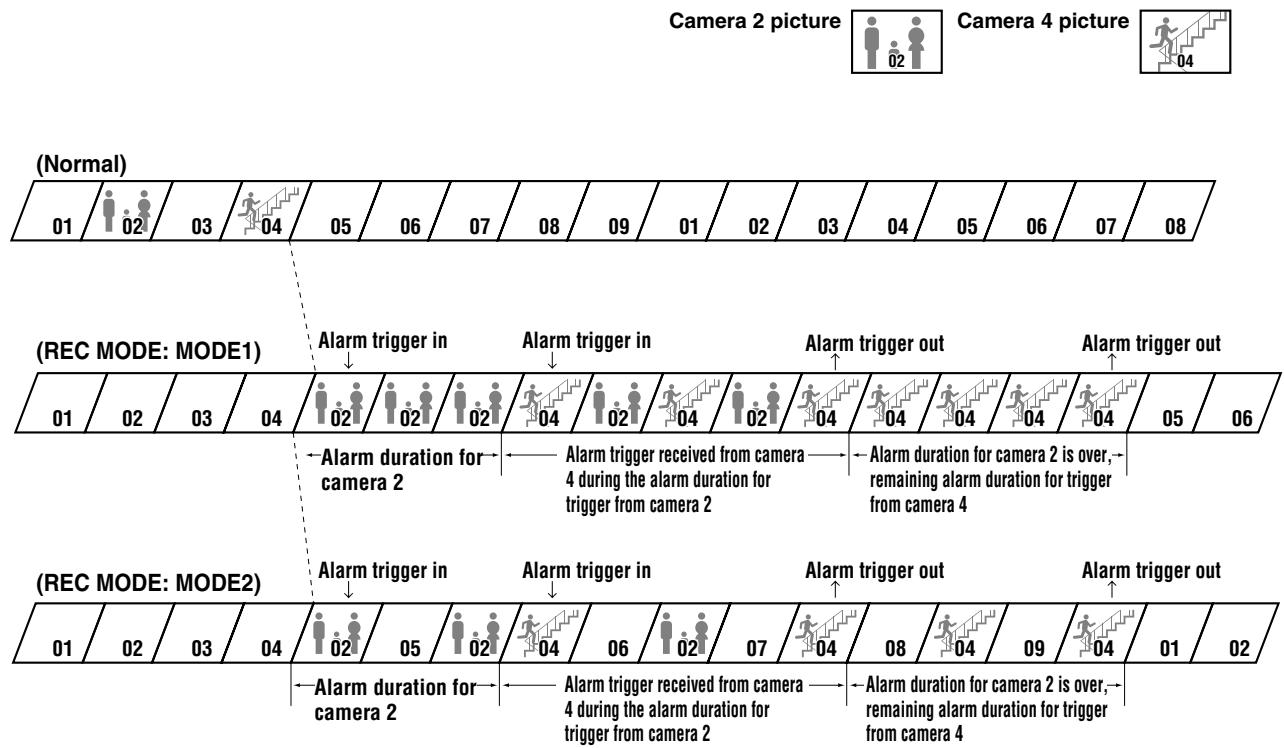
Example 2: Recording on the tape when an alarm trigger is received from camera 4 when an alarm trigger has already been received from camera 2
flowchart
graph TD
    A["01 Normal"] --> B["02"]
    B --> C["03"]
    C --> D["04"]
    D --> E["05"]
    E --> F["06"]
    F --> G["07"]
    G --> H["08"]
    H --> I["09"]
    I --> J["01"]
    J --> K["02"]
    K --> L["03"]
    L --> M["04"]
    M --> N["05"]
    N --> O["06"]
    O --> P["07"]
    P --> Q["08"]

    R["(Rec MODE: MODE1)"] --> S["Alarm trigger in"]
    S --> T["Alarm duration for camera 2"]
    T --> U["Alarm trigger received from camera 4 during the alarm duration for trigger from camera 2"]
    U --> V["Alarm duration for camera 2 is over, remaining alarm duration for trigger from camera 4"]
    V --> W["Alarm trigger out"]
    W --> X["Alarm duration for camera 2 is over, remaining alarm duration for trigger from camera 4"]
    X --> Y["Alarm trigger out"]

    Z["(Rec MODE: MODE2)"] --> AA["Alarm trigger in"]
    AA --> AB["Alarm duration for camera 2"]
    AB --> AC["Alarm trigger received from camera 4 during the alarm duration for trigger from camera 2"]
    AC --> AD["Alarm duration for camera 2 is over, remaining alarm duration for trigger from camera 4"]
    AD --> AE["Alarm trigger out"]
    AE --> AF["Alarm trigger out"]
NOTE: The ACTIVE REC examples are given for function illustration purposes only. The actual recordings will vary according to the various settings.
You can set the automatic sequential display speed on each monitor and the display sequence order. Also, you can have the live and/or recorded picture from certain cameras masked so that they are not visible on-screen.
(MONITOR SET)
Setting the Monitor Display
1 Press the MENU button 6 times to display the (MONITOR SET) menu.
2 Press the ▼ button to highlight the setting to modify. Using the + (or −) button, select the desired setting, then press the ▼ button.
Following this procedure, select the settings or MON1 SEQ. TIMER ... COLOR LEVEL.
3 Press the MENU button to go to the next menu screen, or
Press the EXIT button to exit the menu display.
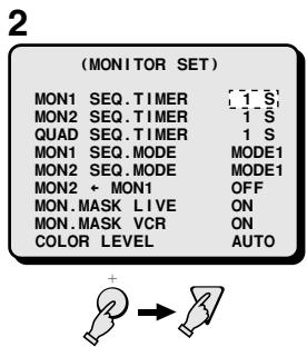
MONITOR SET menu
MON1 SEQ.TIMER (Default setting: 1 S)
To set the full screen automatic sequential display speed (interval) on monitor 1.
The available intervals are: 1 – 30 seconds, INDIV.
MON2 SEQ.TIMER (Default setting: 1 S)
The available intervals are: 1 – 30 seconds, INDIV.
NOTE: If the "INDIV." setting is used, in the (CAMERA SET) menu, enter the desired setting for each camera (see page 40).
QUAD SEQ.TIMER (Default setting: 1 S)
To set the 4 divisions screen automatic sequential display speed (interval).
The available intervals are: 1 – 30 seconds
MON1 SEQ.MODE (Default setting: MODE1)
MODE1: The cameras are displayed sequentially in order (1 to 9).
MODE2: The cameras are displayed sequentially in the order set in the (POSITION SET) menu, when the 9 cameras are displayed in a 9 divisions screen (see page 43).
MON2 SEQ.MODE (Default setting: MODE1)
MODE1: The cameras are displayed full screen sequentially in order (1 to 9).
MODE2: The cameras are displayed sequentially in the order set in the (POSITION SET) menu, when the 9 cameras are displayed in a 9 divisions screen (see page 43).
MON2←MON1 (Default setting: OFF)
ON: The display on monitor 2 will be the same as the one on monitor 1.
OFF: The display mode on monitor 2 will an automatic sequential display or full screen display of live pictures.
MON.MASK LIVE (Default setting: ON)
ON: If, for certain cameras, in the (CAMERA SET) menu, the "MON consider" item is set to "ON", the live picture from those cameras will not be visible on-screen.
OFF: The live picture from all cameras will be visible on-screen regardless of the “MON.MASK” item setting of each camera, in the (CAMERA SET) menu.
MON.MASK VCR (Default setting: ON)
ON: If, for certain cameras, in the (CAMERA SET) menu, the "MON consider" item is set to "ON", the recorded picture from those cameras will not be visible on-screen.
OFF: The recorded picture from all cameras will be visible on-screen regardless of the "MON.MASK" item setting of each camera, in the (CAMERA SET) menu.
NOTE: The individual monitor masking setting is entered for each camera in the (CAMERA SET) menu (see page 39).
COLOR LEVEL (Default setting: AUTO)
AUTO: In divided screen display mode, the colors will be adjusted automatically.
If in divided screen mode the colors depth changes and the image is not clear, press the + (or −) button to select the desired level.
The available settings are:
1, 2, 3, 4, 5, AUTO, 5, 6, 7, 8, 9 (A higher number will set the colors to a depth setting.)
NOTE: Model MPX-MD92 does not have COLOR LEVEL function.
For each camera connected to the unit, you can enter a camera title, such as the camera location, etc., that will be displayed together with the picture from that camera. Also, each camera operating mode and timer recording mode can be set.
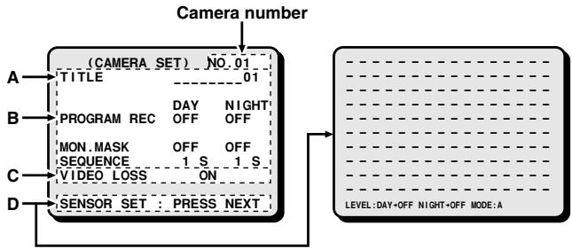
(CAMERA SET)
1 Press the MENU button 7 times to display the (CAMERA SET) menu.
2 The following settings are available.
When finished, press the EXIT button to exit the menu display.
flowchart
graph TD
    A["Camera number"] --> B["(CAMERA SET) NO. 01"]
    B --> C["TITLE 01"]
    B --> D["PROGRAM REC DAY NIGHT OFF"]
    D --> E["MON.MASK OFF ON"]
    E --> F["SEQUENCE 1 S 1 S"]
    F --> G["VIDEO LOSS ON"]
    G --> H["SENSOR_SET PRESS NEXT"]
    H --> I["LEVEL: DAY+OFF NIGHT+OFF MODE:A"]
A camera title (up to 10 characters) to be displayed with the live picture of the camera can be entered.
The camera title displayed location can be set in the (DISPLAY SET) menu.
B A day period and a night period can be set and the following actions can be set accordingly.
B1: PROGRAM REC
Set to ON (or OFF) for programmed recording (or no programmed recording) for each camera.
B2: AL. DURATION
Set the alarm duration for each camera.
B3: MON. MASK
Set to ON (or OFF) for each camera, so that the image from that camera is greyed out (or is not greyed out) and is not visible on the monitor.
Also, in the (MONITOR SET) menu, you must set the monitor masking to be applied to live and/or recorded monitoring.
B4: SEQUENCE
Set the sequential display interval for each camera.
C VIDEO LOSS
Set to ON (or OFF), then in the (VIDEO LOSS SET) menu set the "VIDEO LOSS" item to "INDIV." and enter each setting. If the video signal is interrupted during live picture mode, the image just previous to the interruption is frozen on-screen or color bars can be displayed. However, the frozen image and color bars settings cannot be used together.
D SENSOR SET
Sensor areas can be set for every camera screen in live picture mode. By setting certain areas that operate as video sensors, priority recording of the concerned camera pictures can be done when a movement is detected within the set sensor area.
A Setting the camera title
Each camera is selected by pressing the appropriate SELECT (1 - 9) button.
Example: To set the title "HALL-1F" for camera 3
① Press the SELECT (3) button.
② Using the + (or −) button set the first character “H”, then press the ▶ button.
By pressing the + (or −) button repeatedly, the characters are selected as follows:
- Letters: A, B, C, ....X, Y, Z
- Numbers: 0, 1, ....8, 9
- Symbols: -, :, ., /, *, _ (blank space)
③ Following the same procedure, enter the rest of the title "ALL-1F".
Press the MENU button to go to the next menu screen, or
Press the EXIT button to exit the menu display.
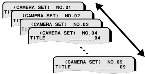
flowchart
graph TD
    A["(CAMERA SET) NO.01"] --> B["(CAMERA SET) NO.02"]
    B --> C["(CAMERA SET) NO.03"]
    C --> D["(CAMERA SET) NO.04"]
    D --> E["......04"]
    E --> F["(CAMERA SET) NO.09"]
    F --> G["......09"]
①②
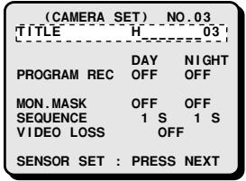
③
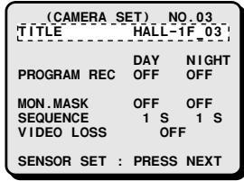
B1 Setting up programmed recording for each camera
1 Press the MENU button twice to display the (TIMER SET) menu, then check that the day and night periods are set as desired. (For more information on the day and night periods settings, see "TIMER SET" on page 27.)
2 Press the MENU button once to display the (VCR SET) menu.
Press the ▼ button to highlight the "PROGRAM REC MODE" setting.
3 Using the + (or −) button, set “MODE1” or “MODE2”. (For more information on each mode operation, see “PROGRAM REC MODE” on page 29.)
4 Press the MENU button four times to display the (CAMERA SET) menu.
5 Press the SELECT (1 – 9) button to select the desired camera (ex: camera 5).
6 Press the ▼ button to highlight the "PROGRAM REC" setting.
① Press the + (or −) button to set "ON" in the DAY column, then press the ▶ button.
② Press the + (or −) button to set "ON" in the NIGHT column.
Programmed recording will be conducted according to the "MODE1" or "MODE2" setting entered in the (VCR SET) menu.
7 Press the MENU button to go to the next menu screen, or
Press the EXIT button to exit the menu display.
CAMERA SET menu
PROGRAM REC (Default setting: DAY and NIGHT to OFF)
ON: When the time set in the (TIMER SET) menu is reached, the pictures from this camera will be recorded in priority.
OFF: Programmed recording will not be done.
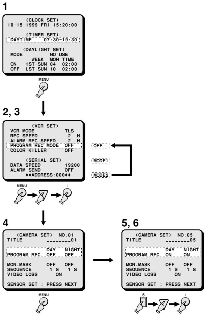
flowchart
graph TD
    A["1 (CLOCK SET)<br>10-15-1999 FRI 15:20:00<br>(TIMER SET)<br>DAYTIME 07:30-19:30<br>(DAYLIGHT SET)<br>MODE NO USE<br>WEEK MON TIME<br>ON 1ST-SUN 04 02:00<br>OFF LST-SUN 10 02:00"] --> B["MENU"]
    B --> C["2,3"]
    C --> D["(VCR SET)<br>VCR MODE TLS<br>REC SPEED 2 H<br>ALARM REC SPEED 2 H<br>PROGRAM REC MODE OFF<br>COLOR KILLER OFF<br>(SERIAL SET)<br>DATA SPEED 19200<br>ALARM SEND OFF<br>**ADDRESS:000**"]
    D --> E["OFF"]
    D --> F["MODE1"]
    D --> G["MODE2"]
    E --> H["4"]
    F --> H
    G --> H
    H --> I["5,6 (CAMERA SET) NO.01<br>TITLE ____01<br>PROGRAM REC OFF OFF<br>MON.MASK OFF OFF<br>SEQUENCE 1 S 1 S<br>VIDEO LOSS ON<br>SENSOR SET : PRESS NEXT"]
    I --> J["5"]
    J --> K["?"]
    K --> L["?"]
    L --> M["+"]
B2 Setting the alarm duration for each camera
1 Press the MENU button twice to display the (TIMER SET) menu, then check that the day and night periods are set as desired. (For more information on the day and night periods settings, see “TIMER SET” on page 27.)
2 Press the MENU button twice to display the (ALARM SET) menu.
3 Using the + (or −) button, set “INDIV.” for the “DURATION” item.
NOTE: In the (CAMERA SET) menu, the item "AL.DURATION" will only be displayed if the "DURATION" item is set to "INDIV.".
4 Press the MENU button three times to display the (CAMERA SET) menu.
5 Press the SELECT (1 – 9) button to select the desired camera (ex: camera 5).
6 Press the ▼ button to highlight the "AL.DURATION" setting.
① Press the + (or −) button to set the desired duration (ex: 20 sec.) in the DAY column, then press the ▶ button.
② Press the + (or −) button to set the desired duration (ex: 30 sec.) in the NIGHT column.
If there is an alarm triggered, the alarm duration will be as set for each camera.
7 Press the MENU button to go to the next menu screen, or
Press the EXIT button to exit the menu display.
CAMERA SET menu
AL. DURATION (Default setting: DAY and NIGHT to 10 S)
If in the (ALARM SET) menu, the item “DURATION” is set to “INDIV.”, enter the desired alarm duration for each camera.
The available durations are:
1, 2, 3, 4, 5, 10, 20 (in 10 seconds increments)... 180, CC, NC, OFF
CC: The alarm will go on as long as the alarm signal is received (minimum 1 second).
NC: The alarm will continue until reset.
OFF: No alarm duration setting.
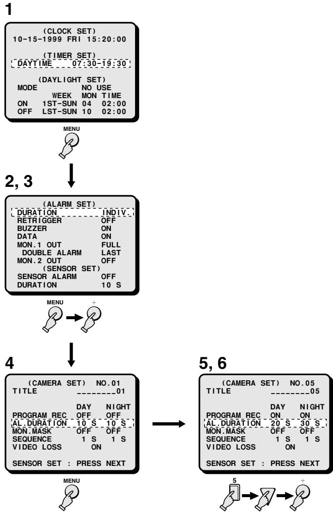
flowchart
graph TD
    A["(CLOCK SET)<br>10-15-1999 FRI 15:20:00"] --> B["(TIMER SET)<br>DAYTIME 07:30-19:30"]
    B --> C["(DAYLIGHT SET)<br>MODE NO USE<br>WEEK MON TIME<br>ON 1ST-SUN 04 02:00<br>OFF LST-SUN 10 02:00"]
    C --> D["MENU"]
    D --> E["2,3"]
    E --> F["(ALARM SET)<br>DURATION INDIV.<br>RETRIGGER OFF<br>BUZZER ON<br>DATA ON<br>MON.1 OUT FULL<br>DOUBLE ALARM LAST<br>MON.2 OUT OFF<br>(SENSOR SET)<br>SENSOR ALARM OFF<br>DURATION 10 S"]
    F --> G["MENU +"]
    G --> H["4"]
    H --> I["(CAMERA SET) NO.01<br>TITLE ----01"]
    I --> J["(CAMERA SET) NO.05<br>TITLE ----05"]
    J --> K["PROGRAM REC DAY NIGHT<br>ON ON<br>AL.DURATION 20 S 30 S<br>MON.MASK OFF OFF<br>SEQUENCE 1 S 1 S<br>VIDEO LOSS ON<br>SENSOR SET : PRESS NEXT"]
    K --> L["5 → 2 → 2 +"]
B3 Setting the monitor masking for each camera
1 Press the MENU button twice to display the (TIMER SET) menu, then check that the day and night periods are set as desired. (For more information on the day and night periods settings, see "TIMER SET" on page 27.)
2 Press the MENU button five times to display the (CAMERA SET) menu.
3 Press the SELECT (1 - 9) button to select the desired camera (ex: camera 5).
4 Press the ▼ button to highlight the "MON consider" setting.
① Press the + (or −) button to set “ON” in the DAY column, then press the ▶ button.
② Press the + (or −) button to set "ON" in the NIGHT column.
5 Press the EXIT button to exit the menu mode and return to live picture mode, then press the MENU button six times to display the (MONITOR SET) menu.
6 Press the ▼ button to highlight the "MON.MASK LIVE" setting.
① Press the + (or −) button to set “ON” for the “MON.MASK LIVE” item, then press the ▼ button.
② Press the + (or −) button to set "ON" for the "MON.MASK VCR" item.
7 Press the MENU button to go to the next menu screen, or
Press the EXIT button to exit the menu display.
CAMERA SET menu
MON. MASK (Default setting: DAY and NIGHT to OFF)
If in the (MONITOR SET) menu, monitor masking is set to "ON" for live and/or recorded monitoring, set this item for each camera.
ON: The pictures from this camera will be masked (not displayed).
OFF: The pictures from this camera will be visible.
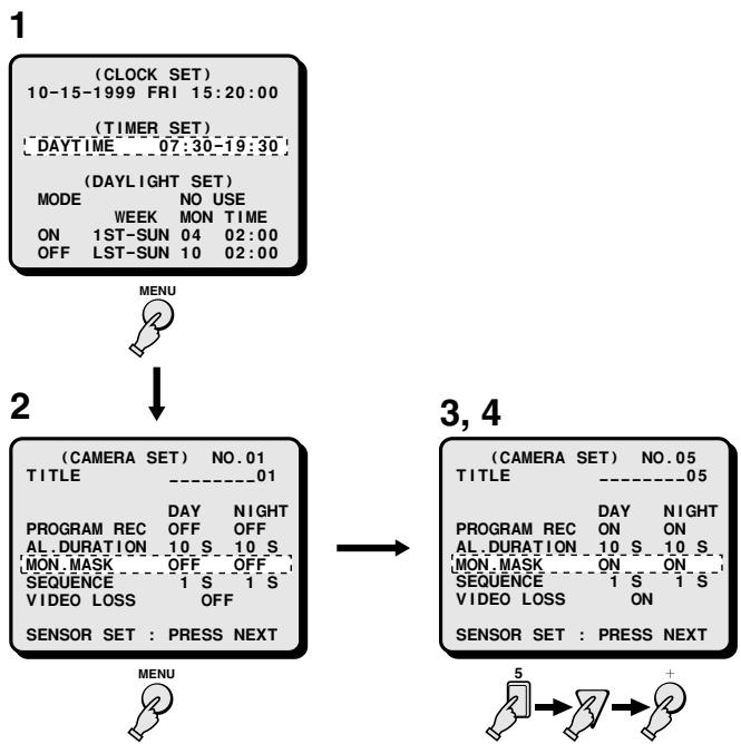
flowchart
graph TD
    A["(CLOCK SET)<br>10-15-1999 FRI 15:20:00"] --> B["(TIMER SET)<br>DAYTIME 07:30-19:30"]
    B --> C["(DAYLIGHT SET)<br>MODE NO USE<br>WEEK MON TIME<br>ON 1ST-SUN 04 02:00<br>OFF LST-SUN 10 02:00"]
    C --> D["MENU"]
    D --> E["(CAMERA SET) NO.01<br>TITLE ----01"]
    E --> F["(CAMERA SET) NO.05<br>TITLE ----05"]
    F --> G["(CAMERA SET) NO.05<br>TITLE ----05"]
    G --> H["(CAMERA SET) NO.05<br>PROGRAM REC ON ON<br>AL.DURATION 10 S 10 S<br>MON.MASK ON ON<br>SEQUENCE 1 S 1 S<br>VIDEO LOSS OFF<br>SENSOR SET : PRESS NEXT"]
    H --> I["5 → 2 → +"]
5,6
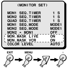
Example
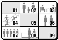
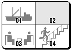
B4 Setting the sequential display interval for each camera
1 Press the MENU button twice to display the (TIMER SET) menu, then check that the day and night periods are set as desired. (For more information on the day and night periods settings, see "TIMER SET" on page 27.)
2 Press the MENU button four times to display the (MONITOR SET) menu.
3 ① Using the + (or −) button, set "INDIV." for the "MON1 SEQ.TIMER" item, then press the ▼ button.
② Using the + (or −) button, set "INDIV." for the "MON2 SEQ.TIMER" item.
4 Press the MENU button once to display the (CAMERA SET) menu.
5 Press the SELECT (1 - 9) button to select the desired camera (ex: camera 5).
6 Press the ▼ button to highlight the "SEQUENCE" setting.
① Press the + (or −) button to set the desired sequential display interval (ex: 10 sec.) in the DAY column, then press the ▶ button.
② Press the + (or −) button to set the desired sequential display interval (ex: 20 sec.) in the NIGHT column.
7 Press the MENU button to go to the next menu screen, or
Press the EXIT button to exit the menu display.
CAMERA SET menu
SEQUENCE (Default setting: DAY and NIGHT to 1 S)
If in the (MONITOR SET) menu, the items "MON1 SEQ.TIMER" and/or "MON2 SEQ.TIMER" are set to "INDIV.", enter the desired sequential display interval for each camera.
The available durations are: 1 to 30 sec., SKIP
SKIP: In automatic sequential display, this camera will not be displayed.
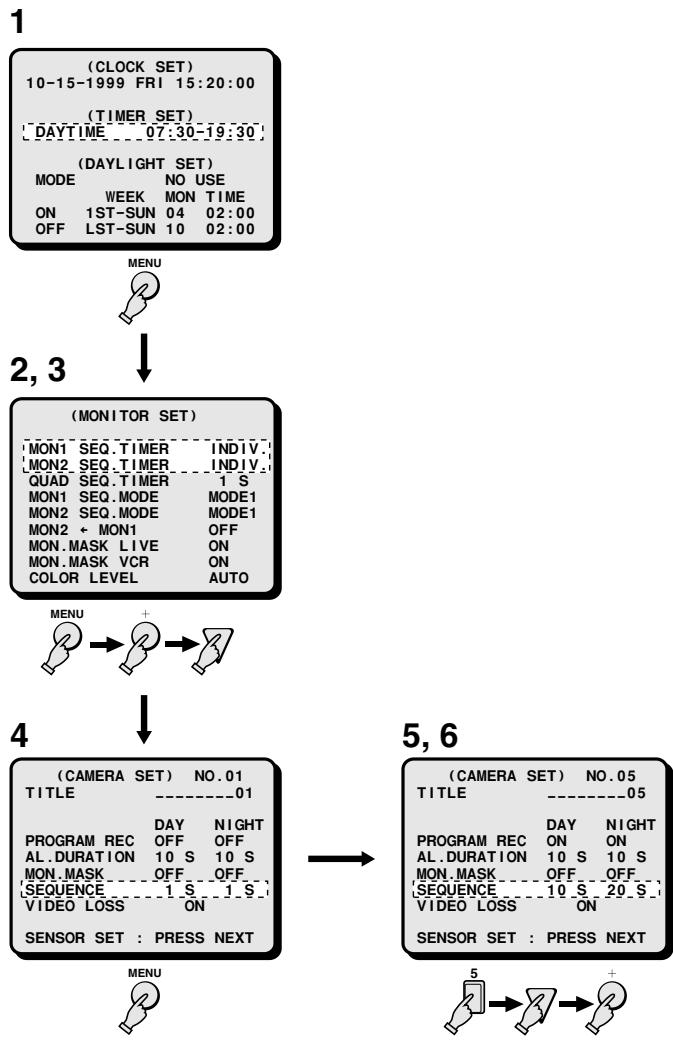
flowchart
graph TD
    A["(CLOCK SET)<br>10-15-1999 FRI 15:20:00"] --> B["(TIMER SET)<br>DAYTIME 07:30-19:30"]
    B --> C["(DAYLIGHT SET)<br>MODE NO USE<br>WEEK MON TIME<br>ON 1ST-SUN 04 02:00<br>OFF LST-SUN 10 02:00"]
    C --> D["MENU"]
    D --> E["2,3"]
    E --> F["(MONITOR SET)<br>MON1 SEQ.TIMER INDIV.<br>MON2 SEQ.TIMER INDIV.<br>QUAD SEQ.TIMER 1 S<br>MON1 SEQ.MODE MODE1<br>MON2 SEQ.MODE MODE1<br>MON2 + MON1 OFF<br>MON consider LIVE ON<br>mon consider VCR ON<br>color level AUTO"]
    F --> G["MENU +"]
    G --> H["4"]
    H --> I["(CAMERA SET) NO.01<br>TITLE 01"]
    I --> J["PROGRAM REC DAY NIGHT<br>OFF OFF<br>AL.Duration 10 S 10 S<br>MON MASK OFF OFF<br>SEQUENCE 1 S 1 S<br>VIDEO LOSS ON<br>SENSOR SET : PRESS NEXT"]
    J --> K["5,6"]
    K --> L["(CAMERA SET) NO.05<br>TITLE 05"]
    L --> M["PROGRAM REC DAY NIGHT<br>ON ON<br>AL.Duration 10 S 10 S<br>MON MASK OFF OFF<br>SEQUENCE 10 S 20 S<br>VIDEO LOSS ON<br>SENSOR SET : PRESS NEXT"]
    M --> N["5 → 2 → 2 +"]
C Setting the video loss operation mode
1 Press the MENU button four times to display the (VIDEO LOSS SET) menu, then press the ▼ button to highlight the “VIDEO LOSS” setting.
2 Using the + (or −) button, set “INDIV.” for the “VIDEO LOSS” item.
3 Press the MENU button twice to display the (CAMERA SET) menu.
4 Press the SELECT (1 - 9) button to select the desired camera (ex: camera 5).
5 Press the ▼ button to highlight the "VIDEO LOSS" setting.
Using the + (or −) button, set "ON" for the "VIDEO LOSS" item.
6 Press the MENU button to go to the next menu screen, or
Press the EXIT button to exit the menu display.
CAMERA SET menu
VIDEO LOSS (Default setting: ON)
Set the action to take when there is an interruption in the live video signal feed.
ON: A video loss alarm trigger is sent.
OFF: No video loss alarm trigger sent.
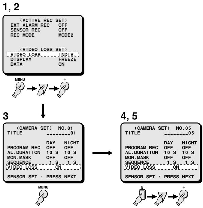
flowchart
graph TD
    A["1, 2"] --> B["(ACTIVE REC SET)<br>EXT ALARM REC OFF<br>SENSOR REC OFF<br>REC MODE MODE2"]
    B --> C["(VIDEO LOSS SET)<br>VIDEO LOSS INDIV.<br>DISPLAY FREEZE<br>DATA ON"]
    C --> D["3"]
    D --> E["(CAMERA SET) NO.01<br>TITLE ----01"]
    E --> F["PROGRAM REC DAY NIGHT<br>OFF OFF<br>AL.DURATION 10 S 10 S<br>MON.MASK OFF OFF<br>SEQUENCE 1 S 1 S<br>VIDEO LOSS ON"]
    F --> G["SENSOR SET : PRESS NEXT"]
    G --> H["4, 5"]
    H --> I["(CAMERA SET) NO.05<br>TITLE ----05"]
    I --> J["PROGRAM REC DAY NIGHT<br>OFF OFF<br>AL.DURATION 10 S 10 S<br>MON.MASK OFF OFF<br>SEQUENCE 1 S 1 S<br>VIDEO LOSS ON"]
    J --> K["SENSOR SET : PRESS NEXT"]
    K --> L["5"]
    L --> M["-->"]
    M --> N["+"]
D Setting the video sensor area position, sensitivity level and response mode
1 Press the SELECT (1 - 9) button to select the desired camera (ex: camera 6).
2 Press the NEXT button.
The live picture from the selected camera and the video sensor setting screen for that camera are displayed.
3 Set the video sensor area position.
① Using the ▼, ▲, ◀ and ▶ buttons, move the cursor to the desired position according to the picture in the background.
② Using the + (or −) button, set A or B for the selected point. Every time the + button is pressed, the setting will change as follows:
$$ \mathbf {A} \rightarrow \mathbf {B} \rightarrow - \rightarrow \mathbf {A}... $$
Repeat steps ① and ② to set all the desired video sensor points of the desired area(s).
- Set the desired point(s) to setting A or B.
- indicates a sensor point without any setting (there are 10 lines of 16 points each), that is not used as video sensor.
- To erase a line of video sensor points (A or B), move the cursor to the line to erase, then press the MENU RESET button.
4 Set the sensor sensitivity level.
① Using the ▲ (or ▼) button highlight the “LEVEL : DAY” setting.
② Press the ▶ button, then using the + (or −) button set the desired sensitivity level for the “DAY” period.
Follow the same procedure to set the desired sensitivity level for the “NIGHT” period.
The available sensitivity levels are: OFF
1, 2, 3...10 (10 being the least sensitive, default setting), OFF.
NOTE: The sensor sensitivity level can only be checked for the time of the setting. (i.e., the night level setting cannot be checked during the day.)
5 Set the sensor response mode.
① Press the ▶ button to highlight the “MODE” setting.
② Using the + (or −) button set the desired mode.
• MODE: A (default setting)
The video sensor will send a trigger when it detects movement at the video sensor area points A.
- MODE: A AND B
Set points A and points B at a predetermined distance, so that only large subjects, that are detected by both video sensor points simultaneously send an alarm trigger. Smaller objects that are detected only by one set of video sensor points at the time will not send an alarm trigger.
• MODE: A AND NB (Fig. 1)
Set the video sensor points A at the centre of the main area, and video sensor points B at the periphery, where no movement will be detected. A trigger will be sent when change is only detected at the video sensor points A, not at the video sensor points B. For example, if the whole screen (A and B) brightness changes due to a change in lighting or sunrays, a trigger is not sent. But, if a change is detected only at the centre of the screen (A), a trigger is sent.
6 Press the NEXT button to return to the (CAMERA SET) menu display, or
Press the EXIT button to exit the menu display.
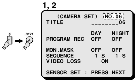
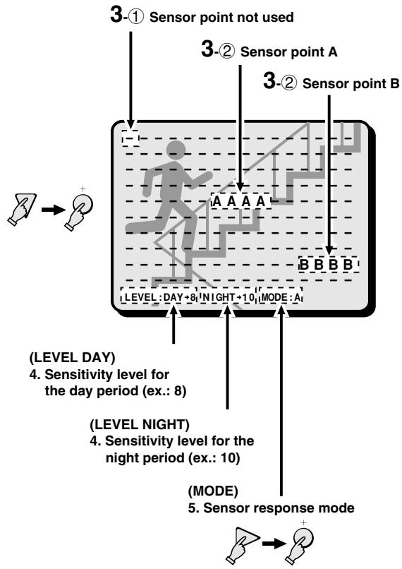
flowchart
graph TD
    A["Sensor point A"] --> B["Day 8"]
    C["Sensor point B"] --> D["Night 10"]
    E["Sensor point not used"] --> F["Day 8"]
    G["Sensor point not used"] --> H["Day 9"]
    I["Sensor point not used"] --> J["Day 10"]
    K["Sensor point not used"] --> L["Day 11"]
    M["Sensor point not used"] --> N["Day 12"]
    O["Sensor point not used"] --> P["Day 13"]
    Q["Sensor point not used"] --> R["Day 14"]
    S["Sensor point not used"] --> T["Day 15"]
    U["Sensor point not used"] --> V["Day 16"]
    W["Sensor point not used"] --> X["Day 17"]
    Y["Sensor point not used"] --> Z["Day 18"]
    AA["Sensor point not used"] --> AB["Day 19"]
    AC["Sensor point not used"] --> AD["Day 20"]
    AE["Sensor point not used"] --> AF["Day 21"]
    AG["Sensor point not used"] --> AH["Day 22"]
    AI["Sensor point not used"] --> AJ["Day 23"]
    AK["Sensor point not used"] --> AL["Day 24"]
    AM["Sensor point not used"] --> AN["Day 25"]
    AO["Sensor point not used"] --> AP["Day 26"]
    AQ["Sensor point not used"] --> AR["Day 27"]
    AS["Sensor point not used"] --> AT["Day 28"]
    AU["Sensor point not used"] --> AV["Day 29"]
    AW["Sensor point not used"] --> AX["Day 30"]
    AY["Sensor point A"] --> AZ["A"]
    BA["Sensor point B"] --> BB["B"]
    BC["Sensor point B'"] --> BD["B"]
    BE["Sensor point B'"] --> BF["B"]
    BG["Sensor point B'"] --> BH["B"]
    BI["Sensor point B'"] --> BJ["B"]
    BK["Sensor point B'"] --> BL["B"]
    BM["Sensor point B'"] --> BN["B"]
    BO["Sensor point B'"] --> BP["B"]
    BQ["Sensor point B'"] --> BR["B"]
    BS["Sensor point B'"] --> BT["B"]
    BU["Sensor point B'"] --> BV["B"]
    BW["Sensor point B'"] --> BX["B"]
    BY["Sensor point B'"] --> BZ["B"]
    CA["Sensor point B'"] --> CB["B"]
    CC["Sensor point B'"] --> CD["B"]
    DD["Sensor point B'"] --> DE["B"]
    FD["Sensor point B'"] --> FDZ["B"]
    DG["Sensor point B'"] --> DGY["B"]
    DGZ["B"] --> DGZ
(Fig. 1)
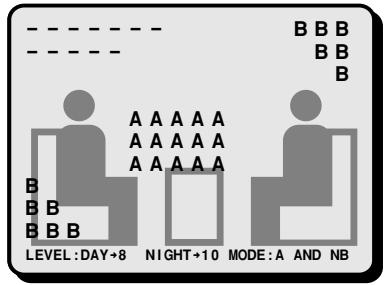
You can set where each camera will be displayed when viewing a split screen display. Setting for 9 divisions split screen is available.
(POSITION SET)
Changing a camera position
1 Press the MENU button 8 times to display the (POSITION SET) menu.
The 9 divisions setting screen is displayed.
2 Example: To interchange the display positions of camera 4 and camera 9.
① Using the ▼, ▲, ◀ and ▶ buttons, move the cursor to the first camera number (04).
② Press the + (or −) button to change the number to the desired camera number (09).
- When a camera is moved to a certain position, it will switch display positions with the camera that was previously displayed at that position.
3 Press the MENU button to go to the next menu screen, or
Press the EXIT button to exit the menu display.
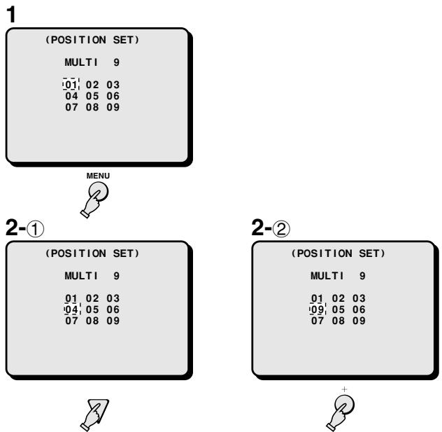
flowchart
graph TD
    A["(POSITION SET)\nMULTI 9\n01 02 03\n04 05 06\n07 08 09"] --> B["MENU"]
    B --> C["2-①"]
    C --> D["(POSITION SET)\nMULTI 9\n01 02 03\n04 05 06\n07 08 09"]
    E["2-②"] --> F["(POSITION SET)\nMULTI 9\n01 02 03\n09 05 06\n07 08 09"]
    F --> G["+"]
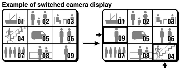
flowchart
graph TD
    A["Example of switched camera display"] --> B["Step 01: Camera Display"]
    A --> C["Step 02: Camera Display"]
    A --> D["Step 03: Camera Display"]
    A --> E["Step 04: Camera Display"]
    A --> F["Step 05: Camera Display"]
    A --> G["Step 06: Camera Display"]
    A --> H["Step 07: Camera Display"]
    A --> I["Step 08: Camera Display"]
    A --> J["Step 09: Camera Display"]
CLOCK AND TITLE DISPLAY SETTINGS
The clock and the camera title settings entered in the menus (CLOCK SET) and (CAMERA SET, TITLE) can be displayed on-screen, and their display position can be set.
(DISPLAY SET)
Setting the clock and title display
1 Press the MENU button 9 times to display the (DISPLAY SET) menu.
2 Using the + (or −) button select the desired setting, then press the ▼ button.
Following this procedure, select the settings for LIVE CLOCK, TITLE and VCR PB CLOCK, TITLE.
3 Press the ▼ button to highlight the "TITLE POSITION" setting.
4 Using the + (or −) button select the desired title display position.
UP: The title will display at the top of the screen.
DOWN: The title will display at the bottom of the screen. (Default setting)
5 Press the NEXT button to switch to the "CLOCK POSITION SET" screen. To return to the (DISPLAY SET) menu, press the NEXT button again.
Press the MENU button to go to the next menu screen, or
Press the EXIT button to exit the menu display.
1, 2
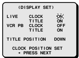
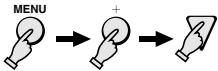
3,4
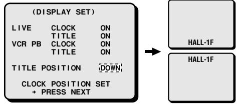
flowchart
graph LR
    A["(DISPLAY SET)"] --> B["LIVE CLOCK ON"]
    A --> C["TITLE ON"]
    A --> D["VCR PB CLOCK ON"]
    A --> E["TITLE ON"]
    A --> F["TITLE POSITION DOWN"]
    A --> G["CLOCK POSITION SET"]
    G --> H["→ PRESS NEXT"]
    B --> I["HALL-1F"]
    G --> J["HALL-1F"]

DISPLAY SET menu
LIVE CLOCK (Default setting: OFF)
OFF: The date and time are not displayed during live picture mode.
ON: The date and time are displayed during live picture mode.
LIVE TITLE (Default setting: ON)
OFF: The camera title is not displayed during live picture mode.
ON: The camera title is displayed during live picture mode.
VCR PB CLOCK (Default setting: OFF)
OFF: The recorded date and time are not displayed during VCR playback picture mode.
ON: The recorded date and time are displayed during VCR playback picture mode.
VCR PB TITLE (Default setting: ON)
OFF: The recorded camera title is not displayed during VCR playback picture mode.
ON: The recorded camera title is displayed during VCR playback picture mode.
Setting the clock display position
1 Press the NEXT button.
The clock display position setting screen is displayed.
2 Using the ▲ (or ▼) button, set the clock display position.
3 Press the NEXT button to return to the (DISPLAY SET) menu
Press the MENU button to go to the next menu screen, or
Press the EXIT button to exit the menu display.
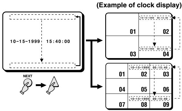
flowchart
graph TD
    A["10-15-1999 15:40:00"] --> B["10-15-1999 00:15:40"]
    A --> C["10-15-1999 02"]
    A --> D["10-15-1999 03"]
    A --> E["10-15-1999 04"]
    F["NEXT"] --> G["Next Step"]
    G --> H["01 02 03"]
    H --> I["04 05 06"]
    I --> J["07 08 09"]
    style A fill:#f9f,stroke:#333
    style F fill:#ccf,stroke:#333
The alarm recordings are done according to the settings entered in the (ALARM SET), (SENSOR SET) and (VIDEO LOSS SET) menus. Information about the alarms (alarm data) is also recorded and can be displayed on-screen.
(ALARM DATA)
Displaying the Alarm Data
1 Press the MENU button 10 times to display the (ALARM DATA) menu.
2 Press the NEXT (or ▼) button to display the next screen of alarm data entries.
The alarm data is displayed from the most recent ones, 8 entries per screen, up to a maximum of 100 entries (13 screens).
Press the ▲ button to display the previous screen of alarm data entries.
3 Press the EXIT button to exit the menu display.
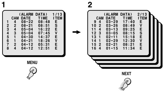
flowchart
graph LR
    A["1: (ALARM DATA) 1/13 CAM DATE TIME ITEM"] --> B["2: (ALARM DATA) 2/13 CAM DATE TIME ITEM"]
    A --> C["MENU"]
    B --> D["NEXT"]
The codes in the ITEM column indicate the type of alarm data.
E: External alarm trigger (see page 46)
S: Video sensor trigger (see page 42, 47)
V: Video loss (see page 46)
NOTE:
- When the number of recorded alarm data entries reaches 100, the oldest ones are erased as new ones are recorded.
- The illustrated alarm data entries screens are a sample of alarm inputs.
ALARMS OPERATIONS
■ LIVE PICTURES MODE ALARM
There are three types of live pictures alarms; the alarms set by an external alarm trigger, the alarms set by a loss of the video signal and the alarms set by the video sensors.
EXTERNAL ALARMS
Connect external inputs such as a door bell, an interphone, etc., to the ALARM IN terminals (1 – 9). These external switches will send triggers to the alarm inputs and the alarm display will be shown in live pictures mode.
Example: If an alarm trigger is received for camera 4 (in multi-display screen)
1 The buzzer is heard and the camera 4 indicator light.
The alarm output changes from HI (5V) to LOW (0V).
2 The image from camera 4 and the camera number (04) will be displayed on monitor 1, EA (External Alarm) will flash at the left of the camera number.
The action taken here will depend on the settings entered in the (ALARM SET) menu (see page 31).
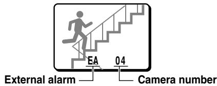
NOTE:
- When the alarm operation is over, the display will return to the mode preceding the alarm trigger.
- An alarm trigger can also be received at a terminal for which a camera is not connected to. In such a case, a grey screen will be displayed and EA (External Alarm) and the corresponding number will be displayed.
Resetting the Alarm
- For an alarm in full screen display mode, press the corresponding SELECT button.
- For an alarm in multi-display screen mode, press the corresponding SELECT button to switch to full screen display mode, then press the same SELECT button one more time.
NOTE:
- The alarm display mode on monitor 1 is selected according to the settings entered in the (ALARM SET) menu.
- During normal monitoring operations the camera select indicator lights according to the displayed camera. If there is an alarm trigger for another camera, the indicator will flash.
VIDEO LOSS ALARM
If there is an interruption of the video signal, the buzzer is heard, and the image just previous to the interruption is frozen on-screen or test chart are displayed and "VIDEO LOSS" will flash on-screen.
The action taken will depend on the settings entered in the (VIDEO LOSS SET) menu (see page 33).
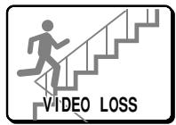
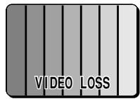
(Test chart)
NOTE:
- If a video signal is not present from the beginning, then “NO VIDEO” will be displayed on a gray screen. This will not trigger a video loss alarm.
- During video loss alarm a frozen image or test chart are displayed on-screen. However, on the video tape, test chart are recorded until the alarm is reset or the video signal is restored.
- Even if the video loss is set to a frozen image, test chart will be displayed when the screen display is switched, or during sequential display.
Resetting the Alarm
- For an alarm in full screen display mode, press the corresponding SELECT button, "NO VIDEO" will be displayed on a grey screen.
- For an alarm in multi-display screen mode, press the corresponding SELECT button to switch to full screen display mode. Then, press the same SELECT button one more time and “NO VIDEO” will be displayed, on a grey screen, on the monitor screen.
NOTE:
- The alarm display mode on monitor 1 is selected according to the settings entered in the (ALARM SET) menu.
- During normal monitoring operations the camera select indicator lights according to the displayed camera. If there is an alarm trigger for another camera, the indicator will flash.
- If the alarm is not reset, "VIDEO LOSS" will be displayed until normal live picture signals are restored. If the display mode is changed it will switch from a frozen picture to test chart.
VIDEO SENSOR ALARM
When in the (SENSOR SET) menu, the “SENSOR ALARM” item is set to “ON” or “AND”, a moving subject detected by the video sensor in the selected area of the image can trigger an alarm.
Example: If movement is detected at camera 4 (in multi-display screen)
1 The buzzer is heard and the SELECT 4 indicator flashes. That particular alarm output changes from OPEN to LOW (0V).
2 The image from camera 4 and the camera number (04) will be displayed on monitor 1, and SA (Sensor Alarm) will flash at the left of the camera number.
The action (such as the alarm duration, alarm recording mode, etc.) taken here will depend on the settings entered in the (SENSOR SET) and the (ACTIVE REC SET) menus (see pages 32, 33).
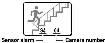
Resetting the Alarm
- For an alarm in full screen display mode, press the corresponding SELECT button during the alarm operation.
- For an alarm in multi-display screen mode, press the corresponding SELECT button to switch to full screen display mode, then press the same SELECT button one more time.
■ RECORDED PICTURES MODE ALARM
There are two types of recorded pictures alarms; the alarms recorded on tape and the alarms set by an external alarm trigger.
Alarms recorded on tape
When a tape with recorded alarm triggers is played back, this unit will trigger an alarm, and the alarm display will appear on the concerned camera picture, but the alarm operation will not be activated as for live pictures mode alarms.
External Alarms
- If during VCR playback, an alarm trigger is received at the ALARM IN terminals on back panel, the concerned camera SELECT indicator flashes, the buzzer is heard and the alarm signal is output at the corresponding ALARM OUT terminal. However, the display on monitor 1 will not switch as for the live pictures mode external alarms operations.
- If in the (ALARM SET) menu, the item "MON.2 OUT" is set to "ON", the alarm screen live pictures will be displayed on monitor 2. To monitor the alarm on monitor 1, switch to live pictures mode.
INTERFACE SPECIFICATIONS
RS232C (9-pin connector layout)
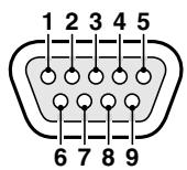
| Pin No. | Signal | Function | Signal direction |
| 1 | - | - | - |
| 2 | RXD | Data reception | Computer → Multiplexer |
| 3 | TXD | Data transmission | Multiplexer → Computer |
| 4 | - | - | - |
| 5 | GND | Ground | - |
| 6 | - | - | - |
| 7 | RTS | Request to send | Multiplexer → Computer |
| 8 | - | - | - |
| 9 | - | - | - |
DATA FORMAT
| Mode | Asynchronous |
| Character length | 8 bits |
| Data transmission speed | 2400, 4800, 9600, 19200 bps(set in the (SERIAL SET) menu) |
| Parity check | None |
| Stop bit | One bit |
■ TRANSMISSION PROTOCOL
The transmission is based on 1 byte units. After the computer has transmitted 1 byte, it will wait for an answer from this unit, then send the following byte of data.
The command ON (F6) is sent to start, and the command OFF (F7) is sent to finish. This unit will receive the commands, and will reply to each command by ACK (0A). (Refer to “COMMAND TABLE 4” on page 52.)
RS-485 (RJ-11 connector layout)
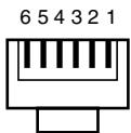
| Pin No. | A terminal signal | B terminal signal |
| 1 | Not used | Not used |
| 2 | Not used | Not used |
| 3 | A signal | B signal |
| 4 | B signal | A signal |
| 5 | Not used | Not used |
| 6 | Not used | Not used |
A: Non-inverting driver output/receiver input
B: Inverting driver output/receiver input
Transmission line: 2 conductors
Transmission system: Half duplex
DATA FORMAT
| Mode | Asynchronous |
| Character length | 8 bits |
| Data transmission speed | 2400, 4800, 9600, 19200 bps(set in the (SERIAL SET) menu) |
| Parity check | None |
| Stop bit | One bit |
■ TRANSMISSION PROTOCOL
A proprietary protocol (SSP: Security Serial Protocol) is used. Operates using a Sanyo controller or a controller using containing this protocol.
SETTING THE DIP SWITCHES
The DIP switches need to be set when a computer, special controller, etc. connected to the RS-232C or RS-485 connectors is used to control the multiplexer. Make sure to turn the multiplexer power off before setting the DIP switches.
(ADDRESS SET)
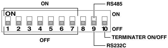
SW No.
1-7: To setup the multiplexer address (only when using the RS-485 connector).
Switch 1 is the least significant bit (LSB) and switch 7 the most significant bit (MSB) (Down: 0, Up: 1)
8: Open (not used)
9: To select the connector used. [232] side (down) for RS-232C, [485] side (up) for RS-485.
10: To setup the termination (only when using the RS-485 connector).
OFF side (down): Not terminated
ON side (up): Terminated
■ RS-232C exclusive use
- Set the DIP switch 9 down ([232] position).
■ RS-485 exclusive use
- Set the address using DIP switches 1 to 7.
Example:
- If the address is 1, set switch 1 to the ON side (up)
- If the address is 10, set switches 2 and 4 to the ON side (up)
-
If the address is 127, set all the switches to the ON side (up)
-
Set the DIP switch 9 up ([485] position).
-
Set the terminator using DIP switch 10
COMMANDS
■ COMMANDS AVAILABLE FROM THE COMPUTER
1-9 (90-98)
To select the picture from a camera to be displayed full screen on monitor 1.
MULTI (82)
To display a 9 divisions split screen on monitor 1.
QUAD (83)
To display a 4 divisions split screen on monitor 1.
PLUS (84)
To display a 6 divisions split screen on monitor 1.
SEQUENCE (87)
To switch the display mode from full screen to sequential display on monitor 1.
ZOOM (85)
To zoom in the picture on monitor 1.
STILL (86)
To freeze the picture on monitor 1.
LIVE (80)
To select the live input mode.
VCR (81)
To select the VCR playback input mode.
MON 2 (88)
To set the output at monitor 2, it can be used in combination with the monitor 1 display.
MENU (74)
To display the menu on monitor 1.
+ (65), - (66)
To select settings (ON/OFF, numbers, letters, symbols) in the menus.
▲ (54), ▼ (64), ▶ (63), ◀ (53)
To change selection in the menus. (To move the cursor up/down, right/left.)
NEXT (75)
To select the sub-menu in (SENSOR SET) and (DISPLAY SET) menus.
EXIT (76)
To go to the next menu, or to exit the menu mode.
MENU RESET (E1)
To reset all the values of the displayed menu to the default values.
CLOCK ADJUST (E0)
To reset the clock minutes and seconds setting to 00:00.
SECURITY LOCK ON (69)
To set the security lock.
SECURITY LOCK OFF (6A)
To cancel the security lock.
INFORMATION GATHERING COMMANDS
STATUS SENSE(D7)
When this command is sent from the computer, this unit will send a 5-byte response (see Table 1).
Fourth and fifth bytes are reserved.
First byte
| Bit | Bit state information | |
| 7 | LIVE/VCR indication | 0: LIVE picture mode1: VCR playback mode |
| 6544 | Monitor 1 display mode indication | 000: Full screen001: 4 divisions split screen010: Multi-display screen011: Plus-display screen100: Menu display |
| 3210 | Monitor 1 displayed channel depending on the display mode indication | (Full screen mode)0000: Channel 10001: Channel 20010: Channel 30011: Channel 40100: Channel 50101: Channel 60110: Channel 70111: Channel 81000: Channel 9(4 divisions split screen)0000: 4 divisions split screen (channels 1, 2, 3, 4)0001: 4 divisions split screen (channels 5, 6, 7, 8)0010: 4 divisions split screen (channels 9)(Multi-display)0000: Full screen1000: 9 divisions split screen(Plus-display)0000: Channel 10001: Channel 20010: Channel 30011: Channel 40100: Channel 50101: Channel 60110: Channel 70111: Channel 81000: Channel 9(Menu display)0001: (LANGUAGE/LANG./IDIO.) menu0010: (CLOCK SET) menu1000: (VCR SET) menu0100: (ALARM SET) menu0101: (ACTIVE REC SET) menu0110: (MONITOR SET) menu0011: (CAMERA SET) menu1110: (POSITION SET) menu0111: (DISPLAY SET) menu1001: (ALARM DATA) menu |
Second byte
| Bit | Bit state information | |
| 7 | EXT/ALARM indication | EXT and ALARM are ON |
| 6 | VIDEO LOSS indication | VIDEO LOSS is ON |
| 5 | SENSOR indication | SENSOR is ON |
| 4 | Reserved | 0 |
| 3 | Monitor 1 display state mode indication | 0000: Normal display mode0001: Sequential display mode0010: Zoomed in mode0011: Still image mode0100: Frozen zoomed in image0101: Zoomed in still image0110: Zoom range setting mode0111: Zoomed in still image range setting mode |
| 2 | ||
| 1 | ||
| 0 |
Third byte
| Bit | Bit state information | |
| 7 | Reserved | - |
| 6 | Reserved | - |
| 5 | Monitor 2 operation | MON2 setup |
| 4 | Monitor 2 operation | 0: Full screen1: Sequential display |
| 3 | Monitor 2 displayed channel | 0000: Channel 10001: Channel 20010: Channel 30011: Channel 40100: Channel 50101: Channel 60110: Channel 70111: Channel 81000: Channel 9 |
| 2 | ||
| 1 | ||
| 0 |
INTERFACE SPECIFICATIONS
ALARM STATUS SENSE(D5)
The external and video loss alarm states are indicated by a 6-byte response (see Table 2).
ALARM STATUS SENSE(D5) byte assignment (Table 2)
First byte
| Bit | |
| 7 | ALARM ON 8 |
| 6 | ALARM ON 7 |
| 5 | ALARM ON 6 |
| 4 | ALARM ON 5 |
| 3 | ALARM ON 4 |
| 2 | ALARM ON 3 |
| 1 | ALARM ON 2 |
| 0 | ALARM ON 1 |
Second byte
| Bit | |
| 7 | |
| 6 | |
| 5 | |
| 4 | |
| 3 | |
| 2 | |
| 1 | |
| 0 | ALARM ON 9 |
Third byte
| Bit | |
| 7 | SENSOR 8 |
| 6 | SENSOR 7 |
| 5 | SENSOR 6 |
| 4 | SENSOR 5 |
| 3 | SENSOR 4 |
| 2 | SENSOR 3 |
| 1 | SENSOR 2 |
| 0 | SENSOR 1 |
Fourth byte
| Bit | |
| 7 | |
| 6 | |
| 5 | |
| 4 | |
| 3 | |
| 2 | |
| 1 | |
| 0 | SENSOR 9 |
Fifth byte
Response when this unit receives a command.
NAK(0B)
Response if this unit did not receive the command.
ALARM(BF)
When there is an alarm, this command is sent as header. Then, the alarm information is sent in a 1-byte transmission (see Table 3).
ALARM information (Table 3)
| Bit | Bit state information | |
| 7 | Alarm information indication | 00: No alarm |
| 6 | 01: External | |
| 10: Video loss | ||
| 11: Sensor alarm | ||
| 5 | Reserved | 0 |
| 4 | Reserved | 0 |
| 3 | Camera number indication | 0000: CAMERA NO. 1 |
| 2 | 0001: CAMERA NO. 2 | |
| 1 | 0010: CAMERA NO. 3 | |
| 0 | 0011: CAMERA NO. 4 | |
| 0100: CAMERA NO. 5 | ||
| 0101: CAMERA NO. 6 | ||
| 0110: CAMERA NO. 7 | ||
| 0111: CAMERA NO. 8 | ||
| 1000: CAMERA NO. 9 |
INTERFACE SPECIFICATIONS
COMMAND TABLE (TABLE 4)
The commands available are indicated in the table.
If a function is not available on the unit, the command will not operate even if sent.
| 0 | 1 | 2 | 3 | 4 | 5 | 6 | 7 | 8 | 9 | |
| 0 | 0 | LIVE | FULL 1 | |||||||
| 1 | 1 | VCR PB | FULL 2 | |||||||
| 2 | 2 | VERSION | MULTI | FULL 3 | ||||||
| 3 | 3 | ← | → | QUAD | FULL 4 | |||||
| 4 | 4 | ↑ | ↓ | MENU | PLUS | FULL 5 | ||||
| 5 | 5 | + | NEXT | ZOOM | FULL 6 | |||||
| 6 | 6 | - | EXIT | STILL | FULL 7 | |||||
| 7 | 7 | SEQ. | FULL 8 | |||||||
| 8 | 8 | MON 2 | FULL 9 | |||||||
| 9 | 9 | SECURITY LOCK ON | ||||||||
| A | ACK | SECURITY LOCK OFF | ||||||||
| B | NAK | |||||||||
| C | GROUP SET* | |||||||||
| D | GROUP CHECK* | |||||||||
| E | GROUP CLEAR* | |||||||||
| F |
| A | B | C | D | E | F | |
| 0 | CLK. ADJ. | |||||
| 1 | MENU RESET | |||||
| 2 | ||||||
| 3 | ||||||
| 4 | ||||||
| 5 | ALARM STATUS SENSE | |||||
| 6 | ON** | |||||
| 7 | STATUS SENSE | OFF* | ||||
| 8 | ||||||
| 9 | ||||||
| A | ||||||
| B | ||||||
| C | ||||||
| D | RS485 TRANSMISSION START* | |||||
| E | RS485 RCV CHECK* | |||||
| F | ALARM* |
* Only RS485
** Only RS232C
SPECIFICATIONS
| Signal format | : Based on NTSC color signal standard (MPX-CD92)Based on NTSC B/W signal standard (MPX-MD92) |
| Camera signal input synchronization | : Asynchronous |
| Camera input terminals (IN) | : VS/VBS, 1.0 Vp-p/75 Ω, BNC connector x 9 |
| Camera output terminals (OUT) | : Throughput of each input, 1.0 Vp-p/75 Ω, BNC connector x 9 |
| VCR input terminal (VCR IN) | |
| Composite input | : VS/VBS, 1.0 Vp-p/75 Ω, BNC connector x 1 |
| S-VHS input terminal (S-VIDEO VCR IN) | : Separate YC signals, DIN connector (S terminal) x 1 (MPX-CD92 only)Y signal: 1.0 Vp-p/75 Ω, unbalanced, synchronous; C signal: 0.286 Vp-p/75 Ω, unbalanced |
| VCR output terminal (VCR OUT) | |
| Composite output | : VS/VBS, 1.0 Vp-p/75 Ω, BNC connector x 1 |
| S-VHS output terminal (S-VIDEO VCR OUT) | : Separate YC signals, DIN connector (S terminal) x 1 (MPX-CD92 only)Y signal: 1.0 Vp-p/75 Ω, unbalanced, synchronous; C signal: 0.286 Vp-p/75 Ω, unbalanced |
| Monitor 1 output terminal (MONITOR OUT 1) | : VS/VBS, 1.0 Vp-p/75 Ω, BNC connector x 1Separate YC signals, DIN connector (S terminal) x 1 (MPX-CD92 only)Y signal: 1.0 Vp-p/75 Ω, unbalanced, synchronous; C signal: 0.286 Vp-p/75 Ω, unbalancedCamera live picture or VCR playback picture signal output: full screen, sequential display, Multi-display screen |
| Monitor 2 output terminal (MONITOR OUT 2) | : VS/VBS, 1.0 Vp-p/75 Ω, BNC connector x 1Camera live picture signal output: full screen (can be set in (MONITOR SET) menu to display the same image as monitor 1) |
| Control terminal (CONTROL) | |
| Alarm input | : No voltage, make-contact switch input x 9 (Low input) |
| Sensor alarm output | : Alarm output x 9 (low output, normally open (NO)) |
| Remote input (R1, R2) | : 2-wire type with resistance-based identification system |
| Alarm output (A) | : DC 5 V, 5.7 kΩ (Low output) |
| Switching input (S) | : Low input, for input signal from SW OUT of timelapse VCR/real time recorder (as per this manufacturer specifications) |
| RS485 control terminal | : RJ-11 type: 2 terminals (A/B), Push-lock type: 3 terminals (A, B, C: Ground) |
| RS-232C terminal | : 9-pin D-SUB |
| Full screen sequence timing | : Available in full screen mode, with interval selectable from 1 – 30 sec. |
| Monitor on-screen display | : Title (up to 10 characters), date, time selectable |
| Menu settings | : 10 menus: Language, Clock, VCR, Alarm, Active REC, Monitor, Camera, Position, Display, Alarm data |
| Alarm sensor | : Internal, 9 channel (each camera input, selectable) |
| Back-up function | : Back-up for up to 30 days of the clock settings after connected for 30 hours continuously |
| Operations | |
| Still | : Available for camera live or VCR playback in full screen and zoomed in pictureCan be set using a menu to operate automatically when there is an alarm trigger |
| 2x zoom | : Available for camera live or VCR playback in full screen and frozen pictureIn full screen mode can switch from frozen to zoomed in picture |
| Power | : AC 120 V, 60 Hz |
| Consumption | : 20 W (MPX-CD92), 18 W (MPX-MD92) |
| Operating environment | : Temperature: 5 to 40°C, Humidity: 10 to 80% |
| Dimensions | : 420 (W) x 86 (H) x 325 (D) mm |
| Weight | : Approx. 4.0 kg |
SANYO INDUSTRIAL MULTIPLEXER WARRANTY
OBLIGATIONS
In order to obtain warranty service, the product must be delivered to and picked up from an Authorized Sanyo Service Center at the user's expense, unless specifically stated otherwise in this warranty. The names and addresses of Authorized Sanyo Service Centers may be obtained by calling the toll-free number listed below.
For product operation, authorized service center referral, service assistance or problem resolution, call
CUSTOMER INFORMATION 1-800-421-5013
Weekdays 8:30 AM – 5:00 PM Pacific Time
For accessories and/or parts, call
PARTS ORDER INFORMATION 1-800-726-9662
Weekdays 8:30 AM – 5:00 PM Pacific Time
THIS WARRANTY IS VALID ONLY ON SANYO PRODUCTS PURCHASED OR RENTED IN THE UNITED STATES OF AMERICA, EXCLUDING ALL U.S. TERRITORIES AND PROTECTORATES. THIS WARRANTY APPLIES ONLY TO THE ORIGINAL RETAIL PURCHASER OR END-USER. THE ORIGINAL DATED BILL OF SALE, SALES SLIP OR RENTAL AGREEMENT MUST BE SUBMITTED TO THE AUTHORIZED SANYO SERVICE CENTER AT THE TIME WARRANTY SERVICE IS REQUESTED.
Subject to the OBLIGATIONS above and EXCLUSIONS below, SANYO Fisher Company warrants this SANYO product against defects in materials and workmanship for the periods specified below. SFC will repair or replace (at its option) the product and any of its parts which fail to conform to this warranty. The warranty period commences on the date the product was first purchased or rented at retail.
| LABOR | PARTS |
| 3 YEARS | 3 YEARS |
EXCLUSIONS
This warranty does not cover (A) the adjustment of customer-operated controls as explained in the appropriate model's instruction manual, or (B) the repair of any product whose serial number has been altered, defaced or removed.
This warranty shall not apply to the cabinet or cosmetic parts, batteries or routine maintenance.
This warranty does not apply to uncrating, setup, installation, removal of the product for repair or reinstallation of the product after repair.
This warranty does not apply to repairs or replacements necessitated by any cause beyond the control of SFC including, but not limited to, any malfunction, defect or failure caused by or resulting from unauthorized service or parts, improper maintenance, operation contrary to furnished instructions, shipping or transit accidents, modification or repair by the user, abuse, misuse, neglect, accident, incorrect power line voltage, fire, flood or other Acts of God, or normal wear and tear.
The foregoing is in lieu of all other expressed warranties and SFC does not assume or authorize any party to assume for it any other obligation or liability.
SFC DISCLAIMS ALL OTHER WARRANTIES EXPRESS OR IMPLIED, WITH REGARD TO THIS PRODUCT (INCLUDING THE WARRANTIES OF MERCHANTABILITY AND FITNESS). IN NO EVENT SHALL SFC BE LIABLE FOR ANY SPECIAL, INCIDENTAL OR CONSEQUENTIAL DAMAGES ARISING FROM THE OWNERSHIP OR USE OF THIS PRODUCT OR FOR ANY DELAY IN THE PERFORMANCE OF ITS OBLIGATIONS UNDER THIS WARRANTY DUE TO CAUSES BEYOND ITS CONTROL. SFC'S LIABILITY FOR ANY AND ALL LOSSES AND DAMAGES RESULTING FROM ANY CAUSE WHATSOEVER, ARISING OUT OF OR IN CONNECTION WITH THE SALE, USE OR OWNERSHIP OF THIS PRODUCT INCLUDING WARRANTOR'S NEGLIGENCE, ALLEGED DAMAGED OR DEFECTIVE GOODS, WHETHER SUCH DEFECTS ARE DISCOVERABLE OR LATENT, SHALL IN NO EVENT EXCEED THE PURCHASE PRICE OF THE PRODUCT.
ATTENTION
For your protection in the event of theft or loss of this product, please fill in the information below for you own personal records.
Model No.
Serial No.
(Located on back or bottom side of unit.)
Date of Purchase
Purchase Price
Where Purchased
- INSTRUCTION MANUAL MANUEL D'INSTRUCTIONS MANUAL DE INSTRUCCIONES
- MPX-CD92 MPX-MD92
- Multiplexer
- Multiplexeur
- Multiplexor
- About this manual
- For the customers in Canada
- CAUTION
- Declaration of Conformity
- Location
- Avoiding Electrical Shock and Fire
- SERVICE
- CONTENTS
- FEATURES
- ACCESSORIES
- ⑯ AC Power socket (AC IN\~)
- ⑰ Power cord holder
- CONNECTION
- CONNECTIONS TO THE S-VIDEO TERMINALS
- CONNECTIONS TO THE ALARM IN AND RS232C/RS485 TERMINALS
- A RS485 (RJ-11) terminal connection
- B Using the push-lock terminals
- C SENSOR ALARM OUT terminals
- REMOTE CONTROLLER CIRCUIT CONNECTIONS
- Live Picture Mode (see page 10)
- NOTE:
- VCR Playback Mode (see page 18)
- Menu Setting Mode (see page 25)
- ① Press the MENU button to display the menu
- ② NEXT button
- ④ EXIT/DISPLAY button (see page 9)
- ⑤ +, - buttons...press repeatedly
- SECURITY LOCK FUNCTION
- Camera Live Picture Mode Lock
- Press the LIVE button for about 3 seconds.
- VCR Playback Mode Lock
- Press the VCR button for about 3 seconds.
- Canceling the Security Lock
- SETTINGS BACKUP FUNCTION
- Battery Life
- Replacing the Battery
- RESET FUNCTION
- Using the ALL RESET button
- Using the MENU RESET Button
- ■ Clock, title display operations
- Press the LIVE button.
- Live picture mode operations steps on monitor 1
- LIVE PICTURE MODE
- Live picture mode operations steps on monitor 2 (see page 17)
- Press a SELECT (1 - 9) button.
- Example: To freeze the image from camera 2
- Press the SELECT 2 button.
- Press the STILL button.
- To cancel the still image display mode
- Example: To zoom in the image from camera 3
- Press the SELECT 3 button.
- Press the ZOOM button.
- To cancel the zoomed in image display mode
- Example: To zoom in the image from camera 4 and set the zoom range
- Example: To freeze the zoomed in image from camera 2
- Automatic sequential full screen display
- Press the SEQUENCE button.
- DIVISIONS SPLIT SCREEN OPERATIONS
- Press the QUAD button.
- Switching the 4 divisions split screen
- Automatic sequential 4 divisions split screen display
- MULTI-DISPLAY SCREEN OPERATIONS
- Press the MULTI button.
- Example: To display the image from camera 9 in the plus screen area
- Automatic sequential plus display
- Example: To display the recorded image from camera 2 in the plus screen area
- Press the VCR button.
- Press the SELECT 2 button.
- Automatic sequential plus display of recorded pictures
- Press the SEQUENCE button.
- To cancel the automatic sequential plus display
- MONITOR 2 OPERATIONS
- Live pictures will be displayed on monitor 2 even during VCR playback mode
- Press the MON 2 button.
- Example: To display full screen the image from camera 4 on monitor 2
- To switch the display mode on monitor 2 from full screen to full screen automatic sequential display
- ■ TO DISPLAY ON MONITOR 2 THE SAME IMAGE AS ON MONITOR 1
- Press the VCR button.
- VCR playback mode operations steps on monitor 1
- VCR playback mode operations steps on monitor 2 (see page 17)
- Example: To freeze the recorded image from camera 2
- Example: To zoom in the recorded image from camera 3
- Example: To zoom in the recorded image from camera 4 and set the zoom range
- Press the SELECT 4 button.
- Press the SELECT 4 button for about 2 seconds.
- Press the ▲, ▼, ◀ or ▶ button repeatedly to move the zoom range frame to the desired area of the image.
- Press the SELECT 4 button.
- Example: To freeze the zoomed in recorded image from camera 2
- Press the STILL button.
- To cancel the still and zoomed in image display modes
- Example: To display the recorded image from camera 9 in the plus screen area
- To cancel the sequential plus display
- (LANGUAGE/LANG./IDIO.)
- Setting the language
- CLOCK AND DAYLIGHT SAVING SETTING
- (CLOCK SET)
- (TIMER SET)
- (DAYLIGHT SET)
- The default settings are:
- ■ TO MAKE CHANGES TO THE SETTINGS
- VCR SETTING AND EXTERNAL CONTROL
- COMMUNICATION SPEED SETTING
- (VCR SET)
- ■ Setting the VCR Output
- VCR SET menu
- If the VCR is not Equipped with a SW (switching) Output Connector
- VCR MODE
- REC SPEED
- With a timelapse VCR
- With a real time VCR
- ALARM REC SPEED
- The available speeds are:
- PROGRAM REC MODE (Default setting: OFF)
- COLOR KILLER (Default setting: OFF)
- VCR SETTING AND EXTERNAL CONTROL COMMUNICATION
- SPEED SETTING
- If the VCR is Equipped with a SW (switching) Output Connector (using the VCR switching signal)
- If a switching signal is not output at the switching terminal
- (SERIAL SET)
- Setting the RS232C/RS485 communication
- SERIAL SET menu
- DATA SPEED (Default setting: 19200 bps)
- ALARM SEND (Default setting: OFF)
- Unit address confirmation
- (ALARM SET)
- Changing the Settings
- ALARM SET menu
- DURATION (Default setting: 10 S)
- The available durations are (seconds):
- RETRIGGER (Default setting: OFF)
- BUZZER (Default setting: ON)
- DATA (Default setting: OFF)
- MON.1 OUT
- FULL (Default setting):
- MON.2 OUT (Default setting: OFF)
- (SENSOR SET)
- Setting the SENSOR SET Mode
- SENSOR SET menu
- SENSOR ALARM (Default setting: OFF)
- The available durations are:
- ACTIVE RECORDING AND VIDEO LOSS
- SETTING
- (ACTIVE REC SET)
- Setting the ACTIVE REC Recording Mode
- ACTIVE REC SET menu
- EXT ALARM REC (Default setting: OFF)
- SENSOR REC (Default setting: OFF)
- REC MODE (Default setting: MODE2)
- (VIDEO LOSS SET)
- Setting the Video Loss Mode
- VIDEO LOSS SET menu
- VIDEO LOSS (Default setting: OFF)
- DISPLAY (Default setting: FREEZE)
- DATA (Default setting: ON)
- ACTIVE REC Settings Examples
- (MONITOR SET)
- Setting the Monitor Display
- MONITOR SET menu
- MON1 SEQ.TIMER (Default setting: 1 S)
- MON2 SEQ.TIMER (Default setting: 1 S)
- QUAD SEQ.TIMER (Default setting: 1 S)
- MON1 SEQ.MODE (Default setting: MODE1)
- MON2 SEQ.MODE (Default setting: MODE1)
- MON2←MON1 (Default setting: OFF)
- MON.MASK LIVE (Default setting: ON)
- MON.MASK VCR (Default setting: ON)
- COLOR LEVEL (Default setting: AUTO)
- The available settings are:
- (CAMERA SET)
- B1: PROGRAM REC
- B2: AL. DURATION
- B3: MON. MASK
- B4: SEQUENCE
- A Setting the camera title
- Example: To set the title "HALL-1F" for camera 3
- B1 Setting up programmed recording for each camera
- CAMERA SET menu
- B2 Setting the alarm duration for each camera
- B3 Setting the monitor masking for each camera
- MASK (Default setting: DAY and NIGHT to OFF)
- B4 Setting the sequential display interval for each camera
- SEQUENCE (Default setting: DAY and NIGHT to 1 S)
- C Setting the video loss operation mode
- VIDEO LOSS (Default setting: ON)
- D Setting the video sensor area position, sensitivity level and response mode
- Press the SELECT (1 - 9) button to select the desired camera (ex: camera 6).
- Press the NEXT button.
- Set the video sensor area position.
- Set the sensor sensitivity level.
- The available sensitivity levels are: OFF
- Set the sensor response mode.
- • MODE: A (default setting)
- - MODE: A AND B
- • MODE: A AND NB (Fig. 1)
- Press the NEXT button to return to the (CAMERA SET) menu display, or
- (POSITION SET)
- Changing a camera position
- CLOCK AND TITLE DISPLAY SETTINGS
- (DISPLAY SET)
- Setting the clock and title display
- DISPLAY SET menu
- LIVE CLOCK (Default setting: OFF)
- LIVE TITLE (Default setting: ON)
- VCR PB CLOCK (Default setting: OFF)
- VCR PB TITLE (Default setting: ON)
- Setting the clock display position
- (ALARM DATA)
- Displaying the Alarm Data
- ALARMS OPERATIONS
- ■ LIVE PICTURES MODE ALARM
- EXTERNAL ALARMS
- Example: If an alarm trigger is received for camera 4 (in multi-display screen)
- Resetting the Alarm
- VIDEO LOSS ALARM
- VIDEO SENSOR ALARM
- Example: If movement is detected at camera 4 (in multi-display screen)
- ■ RECORDED PICTURES MODE ALARM
- Alarms recorded on tape
- INTERFACE SPECIFICATIONS
- ■ TRANSMISSION PROTOCOL
- SETTING THE DIP SWITCHES
- SW No.
- ■ RS-232C exclusive use
- ■ RS-485 exclusive use
- Example:
- COMMANDS
- ■ COMMANDS AVAILABLE FROM THE COMPUTER
- 1-9 (90-98)
- MULTI (82)
- QUAD (83)
- PLUS (84)
- SEQUENCE (87)
- ZOOM (85)
- STILL (86)
- LIVE (80)
- VCR (81)
- MON 2 (88)
- MENU (74)
- + (65), - (66)
- ▲ (54), ▼ (64), ▶ (63), ◀ (53)
- NEXT (75)
- EXIT (76)
- MENU RESET (E1)
- CLOCK ADJUST (E0)
- SECURITY LOCK ON (69)
- SECURITY LOCK OFF (6A)
- INFORMATION GATHERING COMMANDS
- STATUS SENSE(D7)
- ALARM STATUS SENSE(D5)
- ALARM STATUS SENSE(D5) byte assignment (Table 2)
- NAK(0B)
- ALARM(BF)
- COMMAND TABLE (TABLE 4)
- SPECIFICATIONS
- SANYO INDUSTRIAL MULTIPLEXER WARRANTY
- OBLIGATIONS
- EXCLUSIONS
- ATTENTION
Brand : SANYO
Model : MPX-MD92
Category : MiniDisc player