DX-WD1335 - TV Stand Dynex - Free user manual and instructions
Find the device manual for free DX-WD1335 Dynex in PDF.


| Product Type | TV Stand |
| Brand | Dynex |
| Model | DX-WD1335 |
| Dimensions (W x D x H) | Approximately 50 x 20 x 30 inches (127 x 51 x 76 cm) |
| Weight | Approximately 45 lbs (20.4 kg) |
| Material | Engineered wood with laminate finish |
| Color / Finish | Black or Espresso (check product variant) |
| Maximum TV Size | Up to 55 inches |
| Weight Capacity (Top Shelf) | Up to 50 lbs (22.7 kg) |
| Weight Capacity (Per Shelf) | Up to 15 lbs (6.8 kg) |
| Number of Shelves | 2 open shelves |
| Number of Drawers | None |
| Cabinet Doors | Yes, 2 doors with adjustable hinges |
| Assembly Required | Yes, detailed instructions included |
| Tools Required | Phillips screwdriver and hammer (not included) |
| Warranty | 1-year limited warranty |
| Cleaning Instructions | Wipe with a damp cloth; avoid abrasive cleaners |
| Safety Features | Anti-tip kit included; use to secure to wall |
| Ventilation | Open back design for cable management and airflow |
| Country of Origin | China |
Frequently Asked Questions - DX-WD1335 Dynex
User questions about DX-WD1335 Dynex
0 question about this device. Answer the ones you know or ask your own.
Ask a new question about this device
Download the instructions for your TV Stand in PDF format for free! Find your manual DX-WD1335 - Dynex and take your electronic device back in hand. On this page are published all the documents necessary for the use of your device. DX-WD1335 by Dynex.
USER MANUAL DX-WD1335 Dynex
ASSEMBLY INSTRUCTIONS
DX-WD1335
Wood TV Stand

Tools needed...... 2
Parts 3
Hardware......4
Assembly instructions 5
Safety information and specifications

CAUTION: This stand's wood surface is intended only for use with a product not weighing more than 50 lbs (22.7 kg) and having width that will permit it to sit evenly on the stand with no more than one-inch overhang on each side on the top shelf. Using with other products, including products that weigh more than the maximum weight allowed, may result in instability, which may cause possible injury.
Model #: DX-WD1335
Distributed by Best Buy Purchasing, LLC
Weight capacity (top shelf): 50 lbs (22.7 kg)
Weight capacity (lower shelf): 25 lbs (11.34 kg.)
Overall dimensions (W × H × D):
36 × 21.75 × 15.75 in. (91.44 × 55.25 × 40 cm)
Top shelf (W × D): 35.25 × 12.75 in. (89.54 × 32.39 cm)
Usable lower shelf (W × H × D):
30.25 × 5.5 × 12.75 in. (76.84 × 13.97 × 32.39 cm)

Tools needed


No. 2 Phillips screwdriver
Package contents: parts
Note: Some parts have a label on the edge to help distinguish similar parts from each other. Use this illustration to help identify similar parts.

| Item Description Qty. | |
| A Right end 1 | |
| B Left end 1 | |
| C Top 1 | |
| D Lower shelf 1 | |
| E Back 1 |
| Item Description Qty. | ||
| F Right front leg 1 | ||
| G Left front leg 1 | ||
| H Rear leg 2 | ||
| I | Skirt | 1 |
| J | Stop molding | 1 |
Package contents: hardware
Make sure that you have all the hardware necessary to assemble your new TV stand:
| Label | Hardware Qty. | |
| K |  Twist-lock® fastener Twist-lock® fastener | 2 |
| L |  Hidden cam Hidden cam | 13 |
| M |  Cam dowel Cam dowel | 6 |
| N | 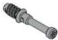 Cam screw Cam screw | 7 |
| O |  Angle bracket Angle bracket | 2 |
| P |  Wood dowel Wood dowel | 2 |
| Label Hardware Qty. | |||
| Q |  | Cam cover | 6 |
| R | [XDIYX] | Glue | 1 |
| S |  | Warning label | 1 |
| T |  |  Black 1-7/8" flat head screw Black 1-7/8" flat head screw | 11 |
| U |  |  Black 9/16" large head screw Black 9/16" large head screw | 4 |

102030405060708090100mm
Step 1:
Caution: Assemble your TV stand on carpeted floor or on the empty carton to avoid scratching your stand or the floor.
Push a Twist-lock ® fastener (K) into each of the two the holes in the back (E).

You'll need:

K(2)
Step 2:
1 Push 13 hidden cams (L) into the ends (A and B), top (C), and back (E). Make sure that the arrows on the hidden cams (L) are pointing toward the closest edge.
2 Insert the metal end of a cam dowel (M) into each hidden cam, except in the top (C) and short edge of each end (A and B).
Important: Do not tighten the hidden cams in this step.

You'll need:

L (13) M (6)
Step 3:
Screw seven cam screws (N) into the front legs (F and G) and stop molding (J).

You'll need:

N (7)
Tightening hidden cams:
In the remaining steps, use these illustrations for instructions on tightening hidden cams.
Warning: Risk of damage or injury. Hidden cams must be completely tightened. Hidden cams that are not completely tightened will loosen, and parts may separate.

In the illustration below, the hidden cam has not been tightened enough.
Make sure that you turn the hidden cam a minimum of 190° to a maximum of 210° . Note the position of the arrow on the hidden cam.


You'll need:

Phillips screwdriver
Step 4:
Align the stop molding (J) with the top (C), then tighten the three hidden cams.


Step 5:
Align the ends (A and B) with the back (E), then tighten the two hidden cams.
Edges with hidden cams

You'll need:

Phillips screwdriver
Step 6:
Caution: Check the parts carefully before assembling. Disassembly of glued parts is extremely difficult.
1 Fill the holes in the stop molding (J) 1/4 to 1/2 full with glue (R), then insert the wood dowels (P) into the holes. Wipe away the excess glue.
2 Drop a few beads of glue (R) into the holes in the ends (A and B).
3 Align the ends (A and B) and the back (E) with the top (C) and the stop molding (J). Make sure that the dowels, Twist-lock ® fasteners, and cam dowels align with the correct holes, then tighten the four hidden cams and two Twist-lock ® fasteners.
Note: Wipe away the excess glue with a damp cloth.
To use a Twist-lock® fastener:
1 Insert the dowel end of the fastener into the hole of the adjoining part.
Note: The dowel end of the fastener must remain fully inserted in the hole of the adjoining part while locking the fastener.
2 Tighten the fastener with a Phillips screwdriver as tight as possible.


Step 7:
1 Attach two angle brackets (O) to the stop molding (J) using two black 9/16" large head screws (U).
2 Fasten the skirt (I) to the stop molding (J) using two black 9/16" large head screws (U).
Note: There are no pre-drilled holes in the skirt. The screws tighten into the groove.

You'll need:

O (2)

U (4)

Phillips screwdriver
Step 8:
1 Align right front leg (F) with the right end (A) and the left front leg (G) with the left end (B), then tighten the four hidden cams (L).
2 Attach the rear legs (H) to the ends (A and B) using four black 1-7/8" flat head screws (T).
Important: Make sure that the rear legs (H) angle out and away from the stand.

You'll need:

Phillips screwdriverT (4)
Step 9:
Fasten the lower shelf (D) to the ends (A and B) and back (E) using seven black 1-7/8" flat head screws (T).


Step 10:
1 Carefully turn your TV stand upright.
2 Apply the warning label (S) to the top (C) so that the TV will hide the label. Peel off the backing and apply the label as shown in the diagram.
Note: This is a permanent label intended to last for the life of the product. After you apply the label, do not try to remove it.
3 Push a cam cover (Q) onto each visible hidden cam.


For customer service, call: 800-305-2204 (U.S./Canada markets)
Need help? Call 800-305-2204
DYNEX™
Certificate of Conformity
-
This certificate applies to the Sauder Woodworking Product identified by this instruction booklet.
-
This certificate applies to the compliance of this product with the CPSC Ban on Lead-Containing Paint (16 CFR 1303).
-
This product was manufactured by: Sauder Woodworking Company
502 Middle Street
Archbold, Ohio 43502
(419) 446-2711
- Date of Manufacture: ____
Lot number: 345399
www.dynexproducts.com (800) 305-2204
Distributed by Best Buy Purchasing, LLC
7601 Penn Ave. South, Richfield, MN 55423 U.S.A.
© 2012 BBY Solutions, Inc.
All rights reserved.
DYNEX is a trademark of BBY Solutions, Inc. Registered in some countries. All other products and brand names are trademarks of their respective owners.
12-0625
ENGLISH
Brand : Dynex
Model : DX-WD1335
Category : TV Stand