
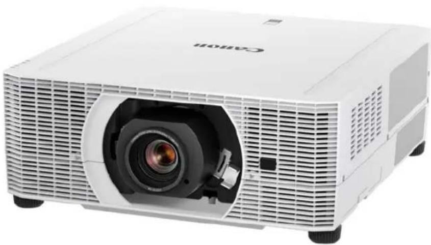
REALiS WUX6700 - Video projector CANON - Free user manual and instructions
Find the device manual for free REALiS WUX6700 CANON in PDF.


| Product Type | Video Projector |
| Brand | Canon |
| Model | REALiS WUX6700 |
| Display Technology | LCOS (Liquid Crystal on Silicon) |
| Native Resolution | WUXGA (1920 x 1200) |
| Brightness | 6000 Lumens |
| Contrast Ratio | 2000:1 |
| Light Source | Laser Phosphor |
| Lens Shift | Vertical: ±60%, Horizontal: ±10% |
| Zoom Ratio | 1.5x Power Zoom |
| Inputs | HDMI (x2), DVI-D, RGB (D-Sub 15-pin), Composite, Component, S-Video |
| Network | Ethernet (RJ-45), Wi-Fi (optional) |
| Weight | Approx. 8.5 kg |
| Dimensions (W x H x D) | 470 x 150 x 400 mm |
| Power Consumption | 500W (max) |
| Noise Level | 35 dB (Eco mode) |
| Warranty | 3 years (parts and labor) |
| Safety | Overheat protection, auto shutoff, security lock |
| Maintenance | Filter cleaning every 1000 hours; no lamp replacement needed |
| Repairability | Spare parts available (fans, power supply, optical engine) |
Frequently Asked Questions - REALiS WUX6700 CANON
User questions about REALiS WUX6700 CANON
0 question about this device. Answer the ones you know or ask your own.
Ask a new question about this device
Download the instructions for your Video projector in PDF format for free! Find your manual REALiS WUX6700 - CANON and take your electronic device back in hand. On this page are published all the documents necessary for the use of your device. REALiS WUX6700 by CANON.
USER MANUAL REALiS WUX6700 CANON
MULTIMEDIA PROJECTOR
WUX7500
WUX6700
WUX5800
User's Manual
natural_image
Exterior view of a white CAHON projector with an open lens (no text or symbols visible)
AISYS
Aspectual Illumination System
CHDBT ^TM ASE
WiFi
HDMI ^TM
CERTIFIED
HIGH DEFINITION MULTIMEDIA INTERFACE
PJLink™
Safety Instructions
Before Use
Basic Guide
Projection Procedure
Convenient Projection Features
Installation Procedure
Connection Procedure
Adjusting the Image
Special Arrangements
Menu Guide
Using Menus
Menu Configuration
Menu Description
Maintenance
Product Specifications
Troubleshooting
How to Use This Manual
Thank you for purchasing a Canon projector.
The WUX7500/WUX6700/WUX5800 Multimedia Projector is a high-performance projector that is capable of projecting a high-resolution computer screen and high-quality digital image on a large screen.
This Manual
This is the user's manual for WUX7500/WUX6700/WUX5800 Multimedia Projector (hereafter, "projector"). The "Basic Guide" describes basic steps before projection and introduces features that are convenient in presentations and other situations.
The “Installation Guide” covers how to install the projector and join a network, and the “Menu Guide” explains setting menus and how to use them.
Read this manual thoroughly to make the most of your projector. We recommend requesting installation by a qualified technician or the Canon Customer Support Center.
Symbols of Button Operations
The projector can be operated using the buttons on the remote control or on the side of the projector. The remote control allows you to operate all functions of the projector.
In this document, the button's operations are shown as below.
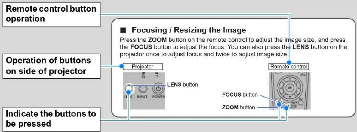
Symbols Used in This Manual
Sections labeled with these symbols give the following kinds of information.

Indicates precautions and information to note when using the projector.
4K6021Z/4K6020Z/4K5020Z/WUX7000Z/WUX6600Z/WUX5800Z/WUX7500/WUX6700/WUX5800
Notification of an Addition to Functions with a Firmware Upgrade
4K6021Z (Ver. 01.010100)
4K6020Z/4K5020Z (Ver. 01.040300)
WUX7000Z/WUX6600Z/WUX5800Z (Ver. 01.040400)
WUX7500/WUX6700/WUX5800 (Ver. 01.040200)
■ Addition of a Dynamic Contrast Function (4K6021Z/4K6020Z/4K5020Z/WUX7000Z/WUX6600Z/WUX5800Z only)
Refer to "Contrast detail adjustment" in this manual.
■ Addition of a Set Value Copy Function (Common to All Models)
You can copy the set values of a projector to other projectors from a computer via a network by connecting this device to wired LAN or wireless LAN.
You cannot copy the following settings.
- [Input settings] Tab Input level / Color space / Progressive / PC-free multi projection / Split screen
•[Image adjustment] Tab Image Priority / Image Mode (*1)
•[Install settings] Tab Zoom / Keystone / Digital image shift / Professional Settings → RGB alignment, Lens shift mode, Marginal Focus and Edge Blending / Lens position
- [System settings] Tab User screen settings → User logo / On screen → Menu position / Remote control channel / Other settings
•[Network settings] Tab Items Other Than PJLink, AMX Device Discovery and Crestron RoomView
•[Information] Tab Contents
- Other Zoom, Focus, Lens shift, Input, Digital zoom, Mute and Freeze
Steps to Copy Set Values
1 Connect the computer and projectors to wired LAN or wireless LAN (*2) (*3).
2 Startup the web browser. Input "http://(IP address of the projector for reading)/professional/read" and then press the [Enter] key.
3 Input the login username and password on the web screen (*4). The READ screen will be displayed.
4 Press the [Start read] button.
5 Press the [OK] button once the reading has been completed.
The read file will be saved in the download folder.
6 Input "http://(IP address of the projector for writing)/professional/write" in the address of the web browser and then press the [Enter] key.
Input the login username and password on the web screen in the same way as with step 3.
The WRITE screen will be displayed.
7 Press the [Browse] button. Select the set value file you saved in step 5 and then press the [Start write] button.
8 Press the [OK] button once the writing has been completed.
* If you wish to copy set values to multiple projectors, repeat steps 6 to 8.
(*1) If the user memory has already been created at the copy source, that content will be reflected in the copy destination. If it has not already been created at the copy source, the user memory at the copy destination will be retained.
(*2) Refer to "Network settings" in this manual for details.
(*3) Operating conditions:
- The projector should be in the projection or standby state (4K6021Z/4K6020Z/4K5020Z/WUX7000Z/WUX6600Z/WUX5800Z)
- The projector should be in the projection state (WUX7500/WUX6700/WUX5800)
- The wired or wireless network function should be on
(*4) Refer to "Password settings" in this manual for details.

Caution
Communications may fail due to a timeout if the standby power settings of the projector are in “Low-power” depending on the browser specifications.
In that case, reload the page and re-read/write.
Table of Contents
How to Use This Manual...... 2
Projector Highlights...... 5
Safety Instructions...... 7
Safety Symbols in this Manual ..... 13
Precautions for Use 14
Power Supply 14
Installation and Use 16
Lamp 19
Remote Control Batteries.... 20
Handling.... 20
For Safe Use 22
Carrying and Installation.... 22
Before Installation.... 24
Precautions When Carrying / Shipping the Projector.... 24
Precautions for Installation...... 24
Wireless LAN (Wi-Fi).... 29
Open Source Software .... 30
Before Use 31
Included Accessories 31
Projector Part Names and Functions.... 32
Remote Control 36
Basic Guide ......41
Projection Procedure...... 42
Step 1 Connect Other Equipment..... 43
Step 2 Turn the Projector On .... 44
Step 3 Select an Input Signal...... 45
Step 4 Adjust the Image .... 46
Step 5 Select the Image Quality (Image Mode).... 47
Turn the Projector Off.... 49
Convenient Projection
Features 50
Convenient Features 50
Projecting Images on a USB Flash Drive 54
Projecting Two Images Side by Side 58
Installation Guide......60
Installation Procedure......61
Relationship Between Projecting Distance and Image Size .... 61
Installing / Removing the Lens Unit ... 65
Installation 68
Adjusting Peripheral Focus 72
Connection Procedure......76
Connecting Other Equipment 76
Connecting to a Network.... 81
Controlling the Projector from a Computer 95
Adjusting the Image .....97
Filling the Screen 97
Adjusting Keystone Distortion ..... 101
Adjustment Using a Test Pattern ..... 105
Special Arrangements .....106
Projecting from Multiple Projectors at Once (Edge Blending) 106
Using PC-Free Multi Projection ..... 112
Menu Guide ......116
Using Menus ....117
Menu Configuration ......120
Menu Description ......126
Input settings 126
Image adjustment 134
Install settings.... 142
System settings 153
Network settings 173
Checking Projector Information ..... 188
Projector Web Screen Menu.....189
Maintenance /
Product Specifications /
Troubleshooting .....206
Maintenance....207
Cleaning the Projector...... 207
Cleaning the Air Filter.... 207
Replacing the Air Filter.... 208
Replacing the Lamp.... 210
Replacement Lamp 211
Lamp Replacement Procedure ..... 212
Table of Contents
Product Specifications ...... 214
Troubleshooting...... 224
LED Indicator Details...... 224
Symptoms and Solutions...... 225
Index...... 232
Option 234
Projector Highlights
High-Resolution LCOS Projection
Projection at 1920x1200 (WUXGA), thanks to high-resolution reflective liquid crystal on silicon (LCOS) panels.
Peripheral Focus Adjustment
Image focus can be adjusted on the edges of the screen, enabling use in dome projection.
HDBaseT Input
The projector supports HDBaseT, a next-generation connectivity standard.
HDBaseT offers a convenient connection for carrying high-quality video and audio signals equivalent to HDMI across distances up to 100 m (328.1') over a single LAN cable.
Lens Shift
Lens shift enables motorized image repositioning up, down, left, or right for greater freedom in installation.
Motorized Zoom and Focus Adjustment
Efficient setup using motorized zoom and focus adjustment.
Full Range of Lens Units Available
Choose the optimal lens unit for the projection distance or purpose.
Superior Video Viewing Experience
Refinements in motion blur reduction make video projection more enjoyable to watch.
Scheduling
Automate projector tasks according to your schedules. Turn the projector on or off, switch input signals, and more.
Edge Blending
Blend the overlapping edges of images from multiple projectors to make the overall image more seamless.
Networked Multi-Projection (NMPJ)
Project images from multiple computers via a network connection.
Wi-Fi Connectivity
In addition to wired LAN connectivity, the projector also supports Wi-Fi.
In Projector Access Point (PJ AP) mode, the projector can be connected to up to five computers without using a wireless access point.
Canon Service Tool for PJ (Canon ST)
An iOS app for easy remote control and status management of projectors over Wi-Fi. Connect to a projector used as an access point (P82), or connect via an existing access point (P82). Note that a password is required when using Canon ST (P189).
Safety Instructions
Before installing and operating the projector, read this manual thoroughly.
This projector provides many convenient features and functions. Operating the projector properly enables you to manage those features and maintain it in good condition for many years to come.
Improper operation may result in not only shortening the product life, but also malfunctions, fire hazards, or other accidents.
If your projector does not seem to be operating properly, read this manual again, check operations and cable connections, and try the solutions in the
“Troubleshooting” section in the back of this manual. If the problem still persists, contact the Canon Customer Support Center.

CAUTION
RISK OF ELECTRIC SHOCK DO NOT OPEN

CAUTION: TO REDUCE THE RISK OF ELECTRIC SHOCK, DO NOT REMOVE COVER (OR BACK). NO USER-SERVICEABLE PARTS INSIDE EXCEPT LAMP REPLACEMENT. REFER SERVICING TO QUALIFIED SERVICE PERSONNEL.

THIS SYMBOL INDICATES THAT DANGEROUS VOLTAGE CONSTITUTING A RISK OF ELECTRIC SHOCK IS PRESENT WITHIN THIS UNIT.

THIS SYMBOL INDICATES THAT THERE ARE IMPORTANT OPERATING AND MAINTENANCE INSTRUCTIONS FOR THIS UNIT IN THE OWNER'S MANUAL.
CAUTION
Not for use in a computer room as defined in the Standard for the Protection of Electronic Computer / Data Processing Equipment, ANSI / NFPA 75.

Safety Precautions
WARNING:
• THIS APPARATUS MUST BE GROUNDED.
• TO REDUCE THE RISK OF FIRE OR ELECTRIC SHOCK, DO NOT EXPOSE THIS APPLIANCE TO RAIN OR MOISTURE.
- This projector produces intense light from the projection lens. Do not stare directly into the lens, otherwise eye damage could result. Be especially careful that children do not stare directly into the beam.
• Install the projector in a proper position. Otherwise it may result in a fire hazard. - Do not cover the ventilation slots on the projector. Heat build-up can reduce the service life of your projector, and can also be dangerous.
- If the projector is unused for an extended time, unplug the projector from the power outlet.
- Do not project the same image for a long time.
An afterimage may remain on the LCD panels due to the characteristics of the panels of the projector.

CAUTION ON HANGING FROM THE CEILING
When hanging the projector from the ceiling, clean the air intake vents and top of the projector periodically with a vacuum cleaner. If you leave the projector unclean for a long time, the cooling fans can be clogged with dust, and it may cause a breakdown or a disaster.
DO NOT SET THE PROJECTOR IN GREASY, WET, OR SMOKY CONDITIONS SUCH AS IN A KITCHEN TO PREVENT A BREAKDOWN OR A DISASTER. IF THE PROJECTOR COMES IN CONTACT WITH OIL OR CHEMICALS, IT MAY BECOME DETERIORATED.
■ READ AND KEEP THIS OWNER'S MANUAL FOR LATER USE.
All the safety and operating instructions should be read before beginning to operate the product.
Read all of the instructions given here and retain them for later use. Unplug this projector from the AC power supply before cleaning. Do not use liquid or aerosol cleaners on the projector. Use a damp cloth for cleaning.
Follow all warnings and instructions marked on the projector.
For added protection of the projector during a lightning storm, or when it is left unattended or unused for long periods of time, unplug it from the wall outlet. This will prevent damage due to lightning and power surges.
Do not expose this unit to rain or use near water... for example, in a wet basement, near a swimming pool, etc...
Do not use attachments not recommended by the manufacturer as they may result in hazards.
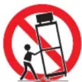
Do not place this projector on an unstable cart, stand, or table. The projector may fall, causing serious injury to a child or adult, and serious damage to the projector. Use only with a cart or stand recommended by the manufacturer, or sold with the projector. Wall or shelf mounting should be carried out in accordance with the manufacturer's directions, and should use a mounting kit approved by the manufacturers.
An appliance and cart combination should be moved with care. Sudden stops, excessive force, and uneven surfaces may cause the appliance and cart combination to overturn.
Slots and openings in the rear and front of the cabinet are provided for ventilation, to insure reliable operation of the equipment and to protect it from overheating.
The openings should never be covered with cloth or other materials, and the bottom opening should not be blocked by placing the projector on a bed, sofa, rug, or other similar surface. This projector should never be placed near or over a radiator or heat register.
This projector should not be placed in a built-in installation such as a book case unless proper ventilation is provided.
Safety Instructions
Never push objects of any kind into this projector through cabinet slots as they may touch dangerous voltage points or short out parts that could result in a fire or electric shock. Never spill liquid of any kind onto the projector.
Do not install the projector near the ventilation duct of air-conditioning equipment.
This projector should be operated using only the type of power source indicated on the marking label. If you are not sure of the type of power supplied, contact the Canon Customer Support Center or local power company.
Do not overload wall outlets and extension cords as this can result in fire or electric shock. Do not allow anything to rest on the power cord. Do not locate this projector where the cord may be damaged by people walking on it.
Do not attempt to service this projector yourself as opening or removing covers may expose you to dangerous voltages or other hazards. Refer all servicing to qualified service personnel.
Unplug this projector from the wall outlet and refer servicing to qualified service personnel under the following conditions:
a. When the power cord or plug is damaged or frayed.
b. If liquid has been spilled into the projector.
c. If the projector has been exposed to rain or water.
d. If the projector does not operate normally after following the operating instructions. Adjust only those controls that are covered in the operating instructions as improper adjustment of other controls may result in damage and will often require extensive work by a qualified technician to restore the projector to normal operating condition.
e. If the projector has been dropped or the cabinet has been damaged.
f. When the projector exhibits a distinct change in performance—this indicates a need for servicing.
When replacement parts are required, be sure the service technician uses replacement parts specified by the manufacturer that have the same characteristics as the original parts. Unauthorized substitutions may result in fire, electric shock, or injury.
Upon completion of any service or repairs to this projector, ask the service technician to perform routine safety checks to determine that the projector is in safe operating condition.
AC Power Cord Requirement
The AC Power Cord supplied with this projector meets the requirements for use in the country you purchased it.
AC Power Cord for the United States and Canada:
The AC Power Cord used in the United States and Canada is listed by the Underwriters Laboratories (UL) and certified by the Canadian Standard Association (CSA).
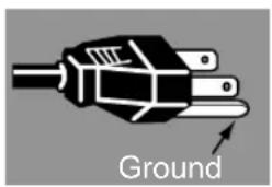
The AC Power Cord has a grounding-type AC line plug. This is a safety feature to ensure the plug fits into the power outlet. Do not try to tamper with this safety feature. Should you be unable to insert the plug into the outlet, contact your electrician.
natural_image
Diagram of a plug with labeled 'Ground' and an arrow pointing to the handle (no other text or symbols)THE SOCKET-OUTLET SHOULD BE INSTALLED NEAR THE EQUIPMENT AND EASILY ACCESSIBLE.

For the U.S. and Canada, LAMP (S) INSIDE THIS PRODUCT CONTAIN MERCURY AND MUST BE RECYCLED OR DISPOSED OF ACCORDING TO LOCAL, MUNICIPAL, STATE, PROVINCIAL, OR FEDERAL LAWS.
For lamp recycling and disposal information please call 1-800-OK-CANON for the U.S. and Canada.

Only for European Union and EEA (Norway, Iceland and Liechtenstein)
These symbols indicate that this product is not to be disposed of with your household waste, according to the WEEE Directive (2012/19/EU), the Battery Directive (2006/66/EC) and/or national legislation implementing those Directives.
If a chemical symbol is printed beneath the symbol shown above, in accordance with the Battery Directive, this indicates that a heavy metal (Hg = Mercury, Cd = Cadmium, Pb = Lead) is present in this battery or accumulator at a concentration above an applicable threshold specified in the Battery Directive.

This product should be handed over to a designated collection point, e.g., on an authorized one-for-one basis when you buy a new similar product or to an authorized collection site for recycling waste electrical and electronic equipment (EEE) and batteries and accumulators. Improper handling of this type of waste could have a possible impact on the environment and human health due to potentially hazardous substances that are generally associated with EEE. Your cooperation in the correct disposal of this product will contribute to the effective usage of natural resources.
For more information about the recycling of this product, please contact your local city office, waste authority, approved scheme or your household waste disposal service or visit www.canon-europe.com/weee, or www.canon-europe.com/battery.
Federal Communication Commission Notice
This device complies with Part 15 of the FCC Rules. Operation is subject to the following two conditions:
- This device may not cause harmful interference, and
- This device must accept any interference received, including interference that may cause undesired operation.
Note: This equipment has been tested and found to comply with the limits for a Class A digital device, pursuant to Part 15 of the FCC Rules. These limits are designed to provide reasonable protection against harmful interference when the equipment is operated in a commercial environment. This equipment generates, uses, and can radiate radio frequency energy and, if not installed and used in accordance with the instruction manual, may cause harmful interference to radio communications. Operation of this equipment in a residential area is likely to cause harmful interference in which case the user will be required to correct the interference at his own expense. The cable with a ferrite core provided with the projector must be used with this equipment in order to comply with Class A of the FCC Rules. Use of a shielded cable is required to comply with Class A of FCC Rules. Do not make any changes or modifications to the equipment unless otherwise specified in the instructions. If such changes or modifications should be made, you could be required to stop operation of the equipment.
Warning:
This is a class A product. In a domestic environment this product may cause radio interference in which case the user may be required to take adequate measures.
The cable with a ferrite core provided with the projector must be used with this equipment in order to comply with Class A.
Use of a shielded cable is required to comply with Class A.
Safety Symbols in this Manual
This section describes the safety symbols used in this manual. Important projector safety information is identified by the following symbols. Always observe the safety information by these symbols.
 | Denotes the risk of death or serious injury from improper handling if the information is not observed. To ensure safe use, always observe this information. |
 | Denotes the risk of injury from improper handling if the information is not observed. To ensure safe use, always observe this information. |
 | Denotes the risk of electric shock from improper handling if the information is not observed. To ensure safe use, always observe this information. |
 | Denotes the risk of burns from improper handling if the information is not observed. To ensure safe use, always observe this information. |
 Prohibition Prohibition | Denotes prohibited actions. |
 Caution Caution | Denotes required actions or information that must be observed. |
Precautions for Use
As this section contains important safety-related information, be sure to read the following carefully beforehand in order to use your projector correctly and safely.

Warning
Power Supply
During installation, keep the projector plug easily accessible so that the projector can be unplugged immediately if necessary, or keep a circuit breaker within reach.
If the following situations occur, turn the power off, remove the power plug from the power outlet and contact the Canon Customer Support Center. Failure to do so could cause a fire or result in an electric shock.

- If smoke is emitted
- If an unusual smell or noise is emitted
- If water or other liquid has entered the projector
- If metal or any other foreign material has entered the projector
- If the projector is knocked over or dropped and the cabinet is damaged
Pay attention to the following points regarding the power source, power plug and handling of the connector. Failure to do so may cause a fire or electric shock.

Prohibition

- Do not place any objects on the power cord and do not allow it to become trapped under the projector.
- Do not cover the power cord with a carpet.
- Do not modify or excessively bend, twist, pull, wind, or bundle the power cord.
- Keep the power cord away from heaters and other sources of heat.
- Do not use a damaged power cord. If the power cord is damaged, contact the Canon Customer Support Center.
- Do not use any power source with a voltage other than the voltage indicated (AC 100 – 240 V).
- Do not insert any metal objects into the contact parts of the power plug or connector.
- The power cord included with this projector is for use exclusively with this product. Do not use this cord for other products.

- Do not remove the power plug or connector with wet hands.

Warning
Pay attention to the following points regarding the power source, power plug and handling of the connector. Failure to do so may cause a fire or electric shock.

Caution

- Insert the power plug and connector securely up to the base. Additionally, do not use a damaged power plug or an outlet that is loose.
- Do not pull the power cord and be sure to hold the power plug or connector when removing. Incorrect handling may damage the power cord.
- When using an extension cord, do not exceed the cord's rated capacity.
- Do not exceed the rated capacity of the outlet (as by using it for more than one piece of equipment), which poses a risk of fire from overheating.
- Periodically inspect the power plug and outlet and remove any dust or dirt from between the plug and the outlet.
- Do not touch the projector itself, the power cord, or the cable if lightening strikes.
- Do not move the projector until you have switched off the power, removed the power plug from the power outlet and unplugged any other cables.
- Unplug the projector before cleaning or maintenance.
- Before you install or remove the lens unit, be sure to unplug the power plug of the projector from the power outlet.

Warning
Installation and Use
Pay attention to the following points regarding installation and handling of the projector. Failure to do so may cause a fire, electric shock or personal injury.

- Do not use the projector where it might get wet, such as outdoors or by bathtubs or showers.
- Do not place containers containing a liquid on top of the projector.
- Make sure to implement anti-fall measures such as an anti-fall wire when installing the projector in high places, for example, installing it on the ceiling.
- Do not remove the cabinet from the projector or disassemble it. The interior of the projector contains high-voltage components as well as parts that are hot. If inspection, maintenance or repair is required, contact the Canon Customer Support Center.
- Do not disassemble or modify the projector (including consumable parts) or the remote control.
- Do not look directly into the exhaust vents during use.
- Do not insert any object into vents in the projector, such as the air intake vent or exhaust vents.
- Do not place a pressurized can in front of the exhaust vents. The pressure of the contents of the can may increase due to heat from the exhaust vents and this could result in an explosion.
- When cleaning off dust or dirt from projector parts such as the lens or filter, never use any spray that is flammable. Internal parts that become hot may ignite and cause a fire.
- Do not use adhesives, lubricants, oils, or alkaline detergents for maintenance of the projector. They could adhere to the cabinet and damage it, possibly resulting in the projector falling from its mounting and causing an accident or personal injury.
- As strong light beams are emitted while the projector is in use, do not look directly into the projector lens. Doing so could cause an

eye injury. Pay particular attention to prevent small children from doing so.
- Operators shall control access to the beam within the hazard distance or install the product at a height that will prevent eye exposure within the hazard distance.

Prohibition

Warning
Pay attention to the following points regarding installation and handling of the projector. Failure to do so may cause a fire, electric shock or personal injury.

Prohibition
- Light from the projector is classified as Risk Group 2 (RG2) according to IEC 62471-5:2015. However, it may be classified as Risk Group 3 (RG3) when a replacement lens with a projection ratio larger than 2.6 is used. Refer to the Hazard Distance table for various replacement lenses (P18).
- Do not hold or install optical instruments (such as magnifying glasses, reflectors, or glasses) in the path of light from the projector. If projected light is refracted or reflected and enters people's eyes, it may result in eye injury.
- No direct exposure to the beam shall be permitted.
- Do not lift the projector alone. Have at least one assistant.
- When setting the projector on a high surface for projection, be sure the surface is flat and stable.
- Do not use the projector on a soft surface such as carpet or sponge mat, etc.
- For ceiling mounting or other installation work, request service from a qualified technician or the Canon Customer Support Center. Poor installation work could result in an accident.
- To avoid hazards such as parts falling when the lens of a ceiling-mounted projector is replaced, request service from a qualified technician or the Canon Customer Support Center.
- Do not use where combustible or explosive gases may occur. The lamp in the projector becomes hot and poses a risk of fire if it ignites.
RG2-3 label
This projector may become RG3 when an interchangeable lens with throw ratio greater than 2.6 is installed. Refer to the manual for the lens list and hazard distance before operation. Such combinations of projector and lens are intended for professional use only, and are not intended for consumer use. Ce projecteur peut devenir RG3 si une lentille interchangeable avec un ratio de projection supérieur à 2.6 est installée. Se reporter au mode d'emploi pour la liste des lentilles et la distance à risque avant l'utilisation. De telles combinaisons de projecteur et de lentilles sont destinées à l'usage de professionnels uniquement, et ne sont pas destinées à l'usage de consommateurs. Dieser Projektor kann RG3 werden, wenn ein Wechselobjektiv mit einem Projektionsverhältnis größer als 2.6 eingesetzt wird. Schauen Sie vor der Inbetriebnahme im Handbuch nach der Objektivliste und dem Sicherheitsabstand. Solche Kombinationen aus Projektor und Objektiv sind nur für den professionellen Einsatz bestimmt, nicht für die Benutzung durch Verbraucher. このプロジェクトは, 投写比2.6より大きい交換レンズを装着すると, RG3になることがある。運転前に取扱説明書のレンズ一覧と障害距離を参照すること。 RG3になるプロジェクトとレンズの組み合わせは、業務用であって、民生用ではない。
Hazard Distance When Equipped with a Replacement Lens (IEC 62471-5)
| Projection ratio*1 | WUX7500 WUX | X6700 WUX5800 | ||
| RS-SL01ST 1.4 | 9-2.24:1 —* | 2 | ||
| RS-SL02LZ | 2.19-3.74:1 | 167 cm (5.5') | 167 cm (5.5') | 154 cm (5.1') |
| RS-SL03WF 0.80:1 —* | 2 | |||
| RS-SL04UL | 3.55-6.94:1 | 400 cm (13.1') | 400 cm (13.1') | 367 cm (12') |
| RS-SL05WZ 1.00-1.50:1 —* | 2 | |||
| RS-SL06UW 0.54:1 —* | 2 | |||
*1 Projection ratios are calculated values based on a 16:10 screen aspect and 100-inch screen size.
*2 Light from the projector is classified as Risk Group 2 (RG2) according to IEC 62471-5:2015.
Hazard Distance
- During projection, looking into the lens from distances closer than this poses a risk of vision impairment or other serious injury.
- When a projection lens with a hazard distance indicated on it is used with the projector, the operator shall either install the product at a height that will prevent eye exposure within the hazard distance or control access to ensure that persons do not approach within the hazard distance.

Warning
Lamp
This projector uses a high-pressure mercury lamp. The mercury lamp has the following characteristics.
- The lamp will gradually become darker over time.
- Impact, abrasion, or use of worn-out lamps may cause lamps to rupture (accompanied by a loud noise) or burn out.
- Lamps are more likely to rupture after the lamp replacement message is displayed (see "Replacing the Lamp" (P210)). Replace the lamp with a new one as soon as possible.
- Useful life of lamps varies widely from lamp to lamp and depending on the environment of use. Some lamps may fail or rupture soon after they are first used.
- Be prepared by keeping a spare lamp.
Note the following precautions during lamp replacement or when a lamp has ruptured.

Caution
- If the lamp ruptures, dust and gas (containing mercury vapor) may come out of the exhaust vents. If this happens, immediately open the windows and doors to provide ventilation to the room.
Ruptured lamps may scatter shards of glass inside the projector. Contact a qualified technician or the Canon Customer Support Center for cleaning and inspection of the projector interior and lamp replacement. - If you accidentally inhale gas from the lamp or get any pieces in your eyes or mouth, consult a doctor immediately.
Note the following precautions when replacing lamps that stop working. Failure to do so could result in personal injury.

Caution
- If illumination suddenly stops, either when you turn the projector on or after it has been on for a while, the lamp may have ruptured. In this case, never attempt to replace the lamp by yourself. Always request service from a qualified technician or the Canon Customer Support Center.
- With ceiling-mounted projectors, the lamp may fall out when you open the lamp cover, or during replacement. During replacement, make sure no one is under the projector, and stand to the side of the lamp cover, not directly under it.

Warning
Remote Control Batteries
Pay attention to the following points regarding handling of batteries. Failing to do so could result in a fire or personal injury.

Prohibition
- Do not heat, short circuit or disassemble the batteries, or place them in a fire.
- Do not attempt to recharge the batteries that are included with the remote control.
- Remove the batteries when they are flat or when the remote control will not be used for a long period of time.
- When replacing the batteries, replace both at the same time. Also, do not use two batteries of a different type at the same time.
- Insert the batteries with the + and – terminals in the correct directions.
- If any liquid from inside the batteries leaks out and contacts your skin, be sure to wash the liquid off thoroughly.

Caution

Caution
Handling
Pay attention to the following points regarding installation and handling of the projector.
- If the projector will not be used for a long period of time, be sure to remove the power plug from the power outlet to ensure safety. Failure to do so presents a risk of fire if dust accumulates on the plug or outlet.

Caution
- Do not plug headphones or earphones into the AUDIO OUT terminal. Doing so may cause hearing impairment.
- Do not set the volume too high initially. Doing so may cause hearing impairment from sudden sounds played at high volume. Lower the volume before turning off the projector, and after startup, raise it gradually.

- Do not touch parts of the cabinet around and above the exhaust vents, which may become hot during projection. Pay particular attention in preventing young children from touching these parts. Additionally, do not place any metal objects around or above the exhaust vents. Such objects may become hot from the projector, which may result in burns or other injury.

Caution
Pay attention to the following points regarding installation and handling of the projector.

- Do not place any heavy objects on top of the projector or sit/stand on it. Pay particular attention to prevent small children from doing so. The projector may be knocked over and this could result in damage or a personal injury.
- Do not place the projector on an unstable or slanted surface. Doing so may cause the projector to fall or be knocked over and could result in a personal injury.
- Do not place any objects in front of the lens during projection. Doing so could cause a fire.
- The projector is provided with a lens shift function to move the lens up, down, left, and right using the motor. Do not touch the lens v
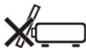
Touching the lens when it is moving may result in personal injury.
- Before replacing the lens unit, wait at least 30 minutes after the projector is turned off to allow the lens unit to cool down. Failure to do so may result in burns or injury.
When handling the lamp, pay attention to the following points.


- Be sure not to handle the lamp immediately after it has been used. Be sure to switch off the power and wait for approximately 1 hour for the lamp and the projector to cool down sufficiently. Failure to do so could result in a burn due to heat from the lamp or projector.
Caution
Carrying and Installation
Pay attention to the following points when carrying or transporting the projector.

- If transportation is necessary, the lens unit should be removed before transporting the projector. If the projector is subjected to excessive impacts during transportation, the lens unit may be damaged.
- This projector is a precision instrument. Do not knock it over or subject it to impacts. Doing so may cause a malfunction.
- Retract the adjustable feet before moving the projector. Leaving the feet extended may cause damage.
- When carrying or holding up the projector after attaching the lens unit, be sure not to hold the lens. Doing so may cause damage to the lens unit.
- Do not touch the lens with bare hands. Any smudges or fingerprints on the lens may affect image quality.
- Protection of the projector cannot be guaranteed if used packaging or shock-absorbent materials are reused. Fragments from shock-absorbent material may also enter the interior of the projector which could cause a malfunction.
Caution
Pay attention to the following points when installing or using the projector.
- Be careful of condensation. If the projector is abruptly taken to a warmer location, or if the room temperature rises abruptly, moisture in the air may condense on the lens or mirror and affect projected images. In this case, wait a while and make sure the moisture has evaporated before resuming use.
-
Do not install the projector in a location where the temperature is high or low. Doing so may cause a malfunction. Ranges for the environment of use and storage are as follows.
-
Environment of use: 0^ (32°F) to 40^ (104°F), 20% to 85% RH
• Storage temperature: -20°C (-4°F) to 60°C (140°F)
- When using the projector at altitudes above 2,300 m (7,545.8'):
Adjust projector installation settings from the menu (P147). Failure to adjust the settings may shorten the lamp life or damage the lamp.
- Do not install the projector facing the wrong direction. Install the projector so that it is not tilted left or right by more than 10^ . Failure to do so may shorten the lamp life or damage the lamp.
- Do not block the air intake or exhaust vents. Blocking the vents may trap heat inside the projector, which may shorten the useful life of optical components or other parts and damage the projector.
- Install the projector leaving at least 50 cm (1.6") between air intake/exhaust vents and walls on each side of the projector. Leave a gap of at least 2 cm (0.8") from the bottom of the projector. There is an air intake underneath the projector. Failure to leave enough space may trap heat inside the projector and damage it.

Caution
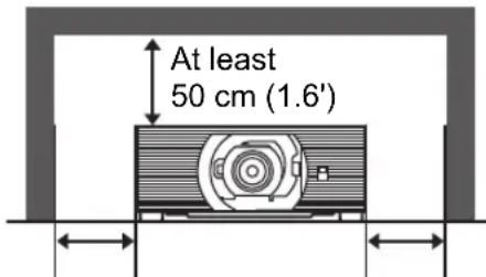
At least 50 cm (1.6')
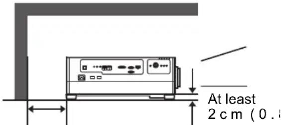
At least 50 cm (1.6')
- Do not place any objects on top of the projector that may change shape or color due to heat.
- Do not install the projector near high-voltage electrical power lines or an electrical power source. This may cause malfunction.
- Clean the air filter regularly (P207). Dust that accumulates inside over long periods without cleaning may eventually damage the projector or affect picture quality.
- Afterimages may occur when the image changes after the same image has been projected for some time. This is due to the nature of the LCD panels and does not indicate a problem. The afterimage will dissipate after a while during normal projection.
Precautions When Carrying / Shipping the Projector
Prepare the projector as described below before carrying it.

- Disconnect the cables connected to the projector. Carrying the projector with the cables attached may cause an accident.
- Retract the adjustable feet before moving the projector. Leaving the feet extended may cause damage.
- Do not subject the projector to strong impacts or vibrations.
Precautions for Installation
Be sure to read “Safety Instructions” and “For Safe Use” (P7 – P22). Also take the following precautions during installation.

- Do not strike the projector or subject it to impact. Doing so may cause a malfunction.
- Do not install the projector standing on one side or in other unsteady positions. The projector may be damaged if it tips over.
■ Do Not Use in the Following Environments

- Locations with excessive humidity, dust, oily smoke or tobacco smoke
Adhesion to the lens, mirrors or other optical parts may reduce image quality. - Near high-voltage power lines or sources of electrical power This may cause malfunction.
- On soft surfaces such as carpets or cushioned mats This may cause a fire or damage the projector.
- Locations with excessive temperature or humidity
- Locations subject to vibration or impact
- Near heat or smoke detectors
- Near the ocean, or near air conditioner vents
- Locations where corrosive gases occur, such as sulfur gas from hot springs
This may damage the projector. Acceptable ranges for operating and storage temperature and humidity are as follows.
* Operating temperature and humidity applies to when the projector is projecting or in standby mode.
| Operating temperature | Operating humidity Storage temperature | |
| 0°C (32°F) – 40°C (104°F) | 20% – 85% | -20°C (-4°F) – 60°C (140°F) |
■ Do Not Touch the Lens with Bare Hands

Do not touch the lens with bare hands. Any smudges or fingerprints on the lens may affect image quality.
■ Allow a 30 Min. Warm Up before Focus Adjustment (P46), if Possible
The focus position may not stabilize immediately after startup, due to lamp heat. When adjusting focus, it is also helpful to use the test pattern (10) (P105, P152).
■ Install at a Sufficient Distance from Walls and Other Obstructions

If the air intake or exhaust vent is blocked, heat will accumulate inside the projector, possibly resulting in a shortened projector lifetime or a malfunction.
Similarly, do not install in narrow, enclosed spaces with poor ventilation. Install in a well-ventilated location.
Ensure a minimum clearance of 50 cm (1.6')
above, on both sides, and behind the projector. Also ensure a minimum clearance of 2 cm (0.8") below the projector.
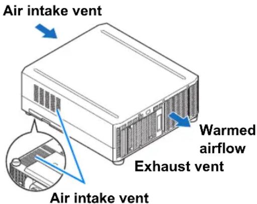
■ Be Careful of Condensation
If the temperature of the room rises suddenly, moisture in the air may condense on the projector lens and mirror, causing the image to become blurred. Wait until the condensation has evaporated for the image projected to return to normal.
■ At Altitudes above 2,300 m (7,545.8'), Adjust the Settings
Projector settings must be adjusted when using the projector at altitudes of 2,300 m (7,545.8') or higher. Specifically, refer to instructions for [High altitude] (P147) in the [Install settings] menu.
■ When Using Mounted on the Ceiling
When the projector is used mounted on the ceiling or installed in a high location, it is necessary to periodically clean the air intake and exhaust vents, and the area around the air filter. Dust that accumulates in intake or exhaust vents may impair ventilation, raising the temperature inside and posing a risk of damage or fire. Use a vacuum cleaner or similar means to remove dust from the intake vent and exhaust vent.
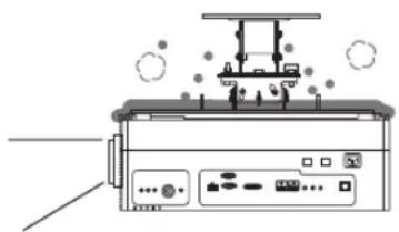
natural_image
Diagram of a printer with base stations and emitting particles (no text or symbols)■ Install Facing in the Correct Direction

- The projector can be installed facing any direction, as shown below. However, projection upward or downward may shorten the useful life of the lamp.
- Do not attempt to install the projector for upward or downward projection by yourself. Always request installation by a qualified technician or the Canon Customer Support Center.
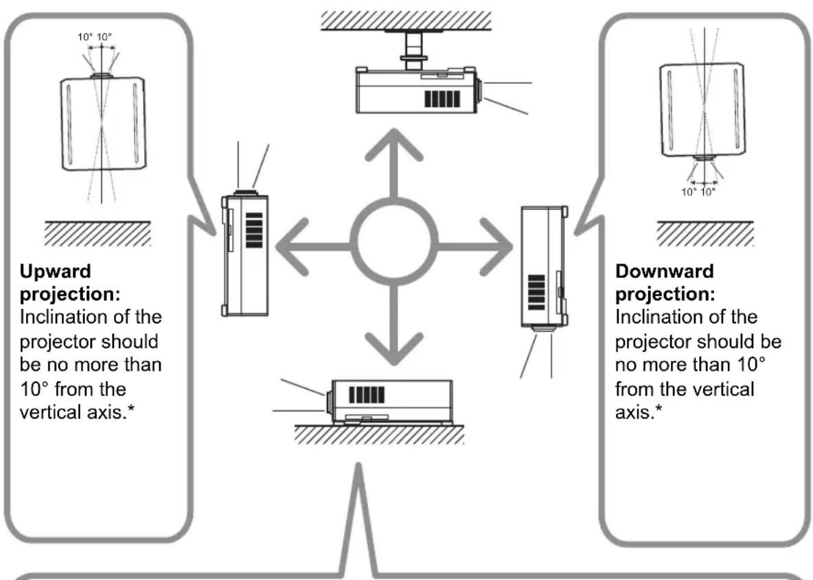
flowchart
graph TD
    A["Upward projection: Inclination of the projector should be no more than 10° from the vertical axis.*"] --> B["Central circle"]
    C["Downward projection: Inclination of the projector should be no more than 10° from the vertical axis.*"] --> B
    B --> D["Central block with internal components"]
    D --> E["Vertical axis with horizontal hatched boundary"]
    style A fill:#f9f,stroke:#333
    style C fill:#f9f,stroke:#333
    style B fill:#ccf,stroke:#333
    style D fill:#ccf,stroke:#333
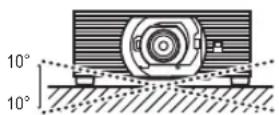
If installing the projector on the floor or hanging from the ceiling, the left/right inclination of the projector should be no more than 10^ .*
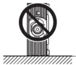
natural_image
Diagram of a mechanical device with a circular crosshair and diagonal line, no text or symbols presentDo not use the projector standing on its side.*
* Failure to do so may damage the lamp.

There are no options for installing the projector other than the ceiling attachment.
Copyright Notice
Please note that enlarging or reducing the size of an image for commercial purposes or public presentation may infringe on the legally protected copyright or the copyright holder of the original material.
Ensure Network Security
Take measures to ensure network security. Note that Canon is not liable in any way for direct or indirect loss from network security incidents, such as unauthorized access.
Before use, configure projector, computer, and network security settings appropriately.
- Set up the projector for connections only within your protected network, behind a firewall or the like, instead of direct Internet connections.
- When using the projector in a wireless network, also configure the Wi-Fi security settings.
- Change the Wi-Fi security key on a regular basis.
About Trademarks
- Ethernet is a registered trademark of Xerox Corporation.
- Microsoft and Windows are registered trademarks or trademarks of Microsoft Corporation in the United States and/or other countries.
• Mac, Mac OS and Macintosh are trademarks of Apple Inc., registered in the United States and/or other countries. - HDMI, the HDMI logo and High-Definition Multimedia Interface are trademarks or registered trademarks of HDMI Licensing, LLC.
- PJLink is a registered trademark of JBMIA and pending trademark in some countries.
- PJLink is a registered trademark, or an application has been submitted for trademark, in Japan, the United States and/or other countries or regions.
• AMX is a registered trademark of Harman International Industries, Inc. - Crestron®, Crestron RoomView®, and Crestron Connected™ are registered trademarks of Crestron Electronics, Inc.
- Extron and XTP are trademarks or registered trademarks of RGB Systems, Inc. in the United States and/or other countries.
- HDBaseT™ and the HDBaseT Alliance logo are trademarks of the HDBaseT Alliance.
• Wi-Fi is a registered trademark of the Wi-Fi Alliance. - Wi-Fi CERTIFIED, WPA, WPA2, and the Wi-Fi CERTIFIED logo are used in reference to methods of configuration developed by the Wi-Fi Alliance.
- All other trademarks are the property of their respective owners.
Wireless LAN (Wi-Fi)
■ Countries and Regions Where Wireless LAN Use Is Permitted
Use of the wireless LAN function is restricted under the laws, etc., of each country and region, and violation of these restrictions may be subject to punishment. Check the Canon website for a list of countries and regions where use of the wireless LAN function permitted.
Canon assumes no responsibility whatsoever for problems, etc., that may arise from use of the wireless LAN function in countries and regions other than those listed.
■ Model Number
WUX7500/WUX6700/WUX5800 (including WLAN module model: CH9-1346)
Complies with IMDA Standards DB00671
Statement on EC directive
Hereby, Canon Inc. declares that this equipment is in compliance with Directive 2014/53/EU. The full text of the EU declaration of conformity is available at the following Internet address:
http://www.canon-europe.com/ce-documentation
Wireless LAN Specifications WUX7500/WUX6700/WUX5800
Frequency band(s): 2,401 MHz – 2,473 MHz
Maximum radio-frequency power: 12.7 dBm
FCC/IC NOTICE
Model: WUX7500/WUX6700/WUX5800 (including WLAN Module Model CH9-1346, FCC ID: AZD221)
This device complies with Part 15 of FCC Rules and ISED's applicable licence-exempt RSS standard(s). Operation is subject to the following two conditions: (1) this device may not cause interference, and (2) this device must accept any interference, including interference that may cause undesired operation of this device.
This transmitter must not be co-located or operated in conjunction with any other antenna or transmitter except Canon accessories supplied or designated for this product.
This equipment complies with FCC/IC radiation exposure limits set forth for an uncontrolled environment and meets the FCC radio frequency (RF) Exposure Guidelines and RSS-102 of the IC radio frequency (RF) Exposure rules. This equipment should be installed and operated keeping the radiator at least 20 cm or more away from person's body.
Open Source Software
The product contains Open Source Software modules.
For details, check the files obtained from "Software Used in This Product" on the download site (http://www.canon.com/iprj/). Please refer to the license information for each module, which is contained in the corresponding file.
Some third-party software permits the distribution of software modules in executable form only under the condition that the source code of such modules be made available freely. For information on how to acquire the source code for such third-party software, contact the distributor from whom the product was purchased.
Before Use
Included Accessories
Before use, make sure the following items are included in the package.
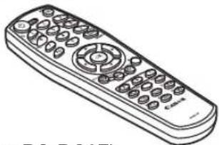
- Remote control
natural_image
Line drawing of a remote control with keypad and scroll (no text or symbols)(part no.: RS-RC07)
- Batteries for the remote control (AAA size x2)
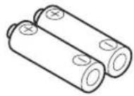
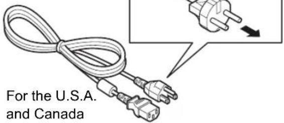
• Power cord (1.8 m / 5.9')
For Continental Europe
- Important Information

natural_image
Blank white rectangle with a thin gray border (no text or symbols)- Warranty Card
Projector Part Names and Functions
■ Front Side
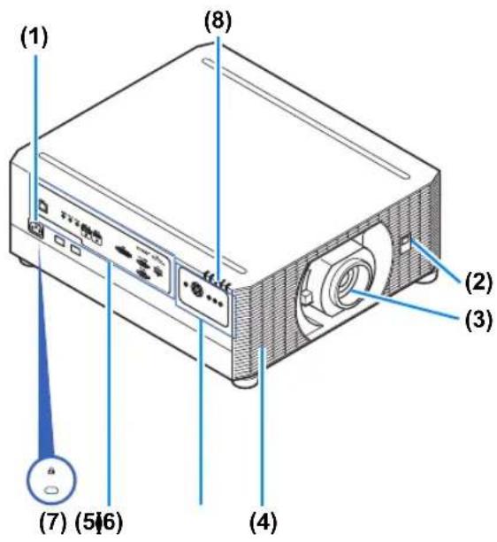
(1) Power cord connector (P80)
(2) Infrared remote receiver (P39)
(3) Lens unit (sold separately)
(4) Air intake vent

Caution
Do not block the air intake. Doing so may cause a malfunction.
(5) Side control (P33)
(6) Terminals and connectors (P35)
(7) Anti-theft lock hole
An anti-theft wire cable (not included) can be connected.
(8) LED indicators (P33)
■ Rear Side
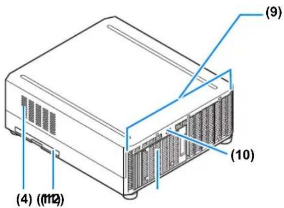
(9) Exhaust vent

Caution
Do not block the air exhaust. Doing so may cause a malfunction.
(10) Infrared remote receiver (P39)
(11) Lamp cover (P212)
(12) Air filter frame (P208)
■ Bottom Side
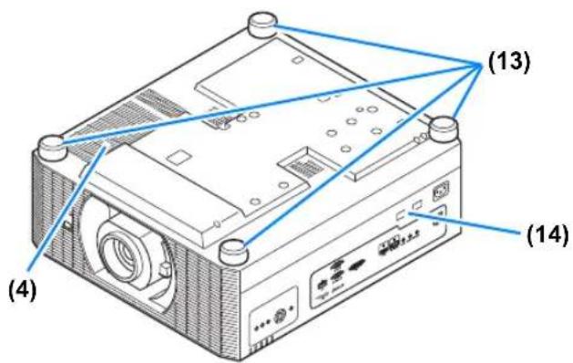
(13) Adjustable feet (P74)
(14) Security bar
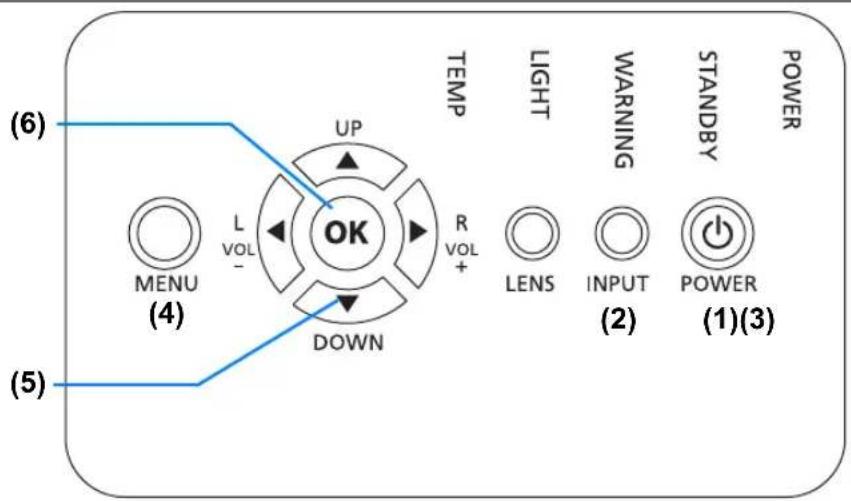
■ Side Control
flowchart
graph TD
    A["MENU (4)"] --> B["UP"]
    B --> C["OK"]
    C --> D["DOWN"]
    D --> E["L VOL -"]
    E --> F["TEMP"]
    F --> G["R VOL +"]
    G --> H["LIGHT"]
    H --> I["WARNING"]
    I --> J["LENS"]
    J --> K["INPUT (2)"]
    K --> L["POWER (1)(3)"]
    style A fill:#fff,stroke:#000
    style B fill:#fff,stroke:#000
    style C fill:#fff,stroke:#000
    style D fill:#fff,stroke:#000
    style E fill:#fff,stroke:#000
    style F fill:#fff,stroke:#000
    style G fill:#fff,stroke:#000
    style H fill:#fff,stroke:#000
    style I fill:#fff,stroke:#000
    style J fill:#fff,stroke:#000
    style K fill:#fff,stroke:#000
    style L fill:#fff,stroke:#000
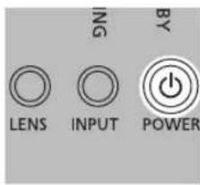
(1) POWER button (P44, P49)
Turns the projector on or off.
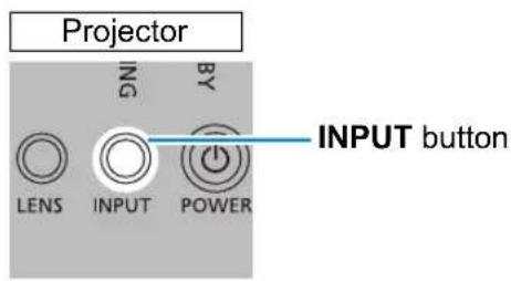
(2) INPUT button (P45)
Switches the input signal.
(3) LENS button
Each time the button is pressed, the screen changes to focus adjustment (P46), zoom (image size) adjustment (P46), or lens shift (image position) adjustment (P68). To adjust, use the [▲/ [ ]or the [▼/ [ ]buttons.
(4) MENU button (P119)
Displays a menu on the screen.
(5) Pointer / VOL buttons (P117)
Up, down, left, or right in menu navigation or other operations. Adjusts the sound volume.
[▲] VOL+ button: Increases the volume.
[▼] VOL- button: Decreases the volume.
(6) OK button (P117)
Determines the item selected from the menu.
■ LED Indicators
The projector status is shown by the LED indicators (off / lit / flashing).
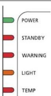
- POWER (green): Lights up or flashes under normal conditions when the power is on.
- STANDBY (red) : Lights up or flashes during standby or when the projector is shut down.
- WARNING (red) : Lights up or flashes when an error occurs.
• LIGHT (orange) : Lights up or flashes when a problem occurs with the lamp or lamp cover.
• TEMP (red) : Lights up or flashes when the internal temperature is high.
LED Indicator Displays
The LED indicators flash or illuminate to indicate the operating status of the projector.
Legend: Example of when the POWER indicator is on; ☐Off : Lit : Flashing
| LED indicator | Operating status | ||||
| POWER (green) | STANDBY (red) | WARNING (red) | LIGHT (orange) | TEMP (red) | |
| Projector not plugged in. | |||||
| In standby mode. | |||||
| Power is on. (Projecting.) | |||||
| Resuming operation (projection) after standby. | |||||
| Cooling down while entering standby or power management mode from power on. | |||||
| In power management mode, with the lamp off. (Flashes green and then red.) | |||||
| Nearly time to replace the lamp (in standby mode). | |||||
| Nearly time to replace the lamp (during projection). | |||||
| Internal temperature is high (in standby mode). | |||||
| Internal temperature is high (during projection). | |||||
| A lamp error has occurred. | |||||
| A temperature error has occurred. | |||||
| The lamp cover is open. | |||||
| Flashes 3 times: Air filter errorFlashes 4 times: Fan errorFlashes 5 times: Power errorFlashes 6 times: Lens unit error | |||||

Caution
A flashing LIGHT indicator means that it is almost time to replace the lamp. Prepare a replacement lamp.
■ Terminals and Connectors
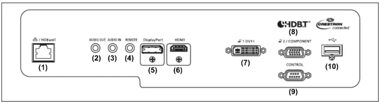
(1) LAN / HDBaseT port (P79, P81)
Receives HDBaseT input including digital video and audio signals.
Carries both video and audio signals across a single LAN cable (shielded twisted pair).
This port can also be used to connect the projector to a network.
(2) AUDIO OUT terminal (P79)
Outputs the audio to external AV equipment. This outputs the audio signal that corresponds to the projected image signal.
(3) AUDIO IN terminal (P79)
Receives audio input. Audio supplied to this terminal is played through the internal speaker when you set [Audio in terminal select] to [Audio in] (P160).
(4) Terminal for wired remote control (P40)
This terminal is used to connect the optional remote control (RS-RC05) using a cable.
(5) DisplayPort port (P77)
Receives DisplayPort input including digital video and audio signals.
Carries both video and audio signals across a single cable.
(6) HDMI terminal (P76)
Receives HDMI input including digital video and audio signals.
Carries both video and audio signals across a single cable.
(7) DVI-I terminal (P77)
Connects the external monitor output from a computer.
Receives digital PC signal (Digital PC).
A VGA-DVI-I cable can also be used to receive analog computer signals (Analog PC-1).
(8) Analog PC-2 / COMPONENT terminal (P78)
Receives the analog PC signal (Analog PC-2).
A component cable can be used to receive the component image signal (Component).
(9) Service port (P221)
Used to control the projector with user commands (P222 - P223).
(10) USB port (P54, P112, P131, P171)
Connects a USB flash drive. Used for projection of images on a USB flash drive, or for firmware updates.
Remote Control
■ Part Names and Functions
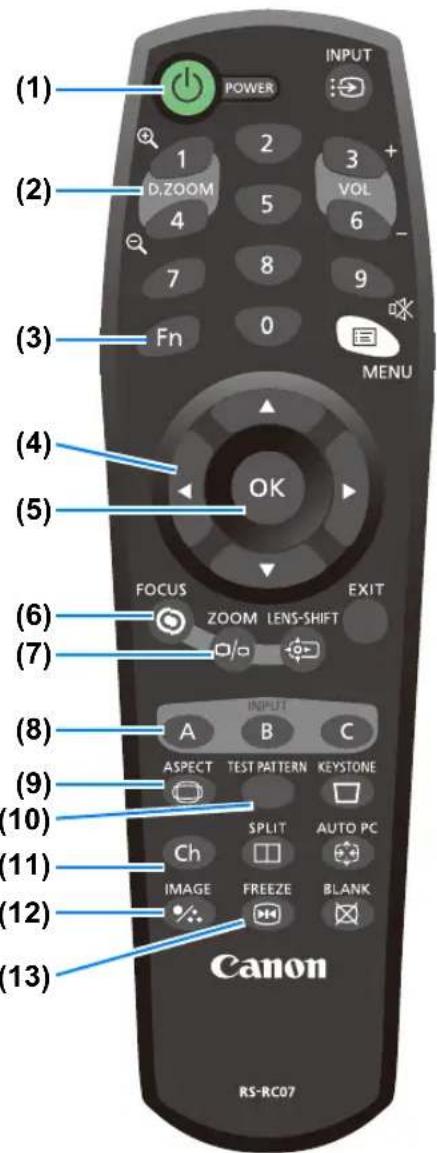
(1) POWER button (P44, P49)
Turns the projector on or off.
(2) D.ZOOM button (P53)
Zooms the image in or out digitally.
[1] button: Zooms the image in (up to 12x).
[4] button: Zooms the image out (1x minimum).
[▲/ [ ]▼[ ] /◀] buttons:
Move the zoom-in location.
(3) Fn button (P160)
Can be assigned a specific function.
(4) Pointer buttons (P117)
Selects the upper, lower, left or right item in the menu. Also used to assign a channel to the remote control.
(5) OK button (P117)
Determines the item selected from the menu.
(6) FOCUS button (P46)
Adjusts focusing.
[▲/ [ ]buttons:
Moves the focus position further away.
[▼/ [ ]◀buttons:
Moves the focus position nearer.
(7) ZOOM button (P46)
Adjusts the image size.
[▲/ [ ]buttons:
Increase the image size.
[▼/ [ ]◀buttons:
Decrease the image size.
(8) INPUT A-C button (P160)
Can be assigned to input signal selection (one source for each of the three buttons).
(9) ASPECT button (P100, P127)
Changes the aspect ratio of the projected image.
(10) TEST PATTERN button (P152)
Displays the test pattern.
(11) Ch button (P159)
Changes the remote control channel.
(12) IMAGE button (P47)
Switches the image mode (image quality).
(13) FREEZE button (P50)
Freezes the projected image.
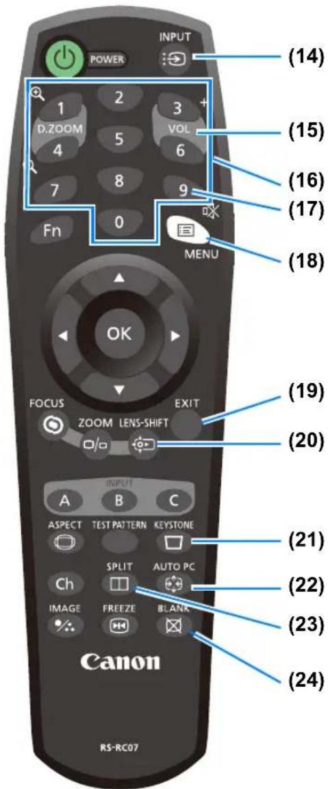
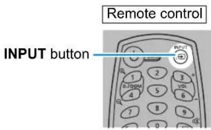
(14) INPUT button (P45)
Switches the input signal.
(15) VOL button (P52)
Adjusts the sound volume.
[3] button: Increases the volume.
[6] button: Decreases the volume.
(16) Number buttons (P165, P174, P176)
Enter password and TCP/IP setting values.
(17) MUTE button (P52)
Mutes the sound.
(18) MENU button (P119)
Displays a menu on the screen.
(19) EXIT button (P118)
Cancels functions such as menu display or test pattern during operation and returns to the image display.
(20) LENS-SHIFT button (P68)
Moves the lens up, down, left, or right.
[▲/ [ ]▼[ ] / [◀] buttons:
Moves the image.
(21) KEYSTONE button (P101)
Corrects keystone distortion.
The [Keystone] setting enables both horizontal/vertical keystone correction (by adjusting top/bottom/left/right length) and corner correction.
- Moves the image up, down, left, or right when the screen aspect setting is [16:9 D. image shift] or [4:3 D. image shift].
- To move the image, use the [ ]/ [ ]▼ or the [ ]/ [ ]buttons.
(22) AUTO PC button (P127)
Adjusts the image for optimal projection of computer signals when analog PC input is used.
(23) SPLIT button (P58)
Activates the split screen function.
(24) BLANK button (P50)
Temporarily blacks out the image.
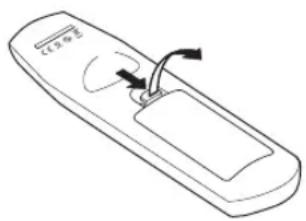
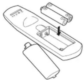
■ Installing Remote Control Batteries
1 Open the battery compartment lid. Slide the lid while pressing it down.
2 Insert batteries. Insert 2 new AAA batteries in the compartment with the + and – terminals positioned correctly.
3Close the compartment lid. Slide the lid until you hear a click to securely close it.
natural_image
Line drawing of a remote control device with battery and switch components (no text or symbols)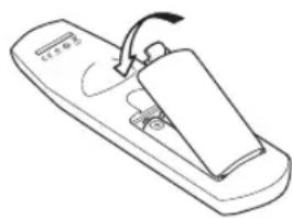
natural_image
Line drawing of a handheld device with a clip and handle (no text or symbols)
- If buttons on the remote control are inoperative when you attempt to operate the projector, replace the batteries with new ones.
- Do not drop the remote control or subject it to impact.
- Do not spill any liquids on the remote control. Doing so may cause a malfunction.


Pay attention to the following points when handling the batteries. Failing to do so could result in a fire or personal injury.
- Do not heat, short circuit or disassemble the batteries, or place them in a fire.
- Do not attempt to recharge the batteries that are included with the remote control.
- Remove the batteries when they are flat or when the remote control will not be used for a long period of time.
- When replacing the batteries, replace both at the same time. Also, do not use two batteries of a different type at the same time.
- Insert the batteries with the + and – terminals in the correct directions.
- If any liquid from inside the batteries leaks out and contacts your skin, be sure to wash the liquid off thoroughly.
■ Remote Control Operating Range
The remote control is an infrared type. Point it at the infrared remote receiver on the front or rear of the projector to operate it.
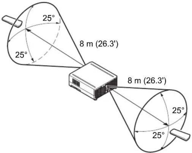

- Use the remote control no further than approximately 8 m (26.3') from the projector.
- Use the remote control within an angle of 25^ in any direction from directly in front of the infrared remote receiver.
- The remote control may be inoperative if there is an obstacle between the remote control and the projector or the infrared remote receiver on the projector is exposed to direct sunlight or strong light of lighting equipment.
- When you use 2 or more projectors at the same time, change the channel settings to prevent the 2 remote controls from interfering with each other (P159).
■ Using an Optional Wired Remote (RS-RC05)
To use a wired remote control with the projector, use the RS-RC05, sold separately. Use a cable with a 3.5 mm stereo mini jack (not included).
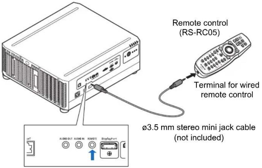

- Infrared operations cannot be performed if a cable is connected to the projector or the remote control.
- Use a cable with a 3.5mm stereo mini jack (not included) with a length of 30m (98.4') or less.
Basic Guide
Projection Procedure
The steps to prepare for projection are as follows.
Step 1 Connect Other Equipment (P43)

Configure the computer's network settings (P84)
Step 2 Turn the Projector On (P44)

Step 3 Select an Input Signal (P45)

Step 4 Adjust the Image (P46)

Step 5 Select the Image Quality (Image Mode) (P47)

Other Projection

- Projecting images stored on a USB flash drive (P54)
- Split-screen display from multiple connected devices (P58)
- Projecting a single image from multiple projectors (P112)
Turn the Projector Off (P49)
Step 1 Connect Other Equipment
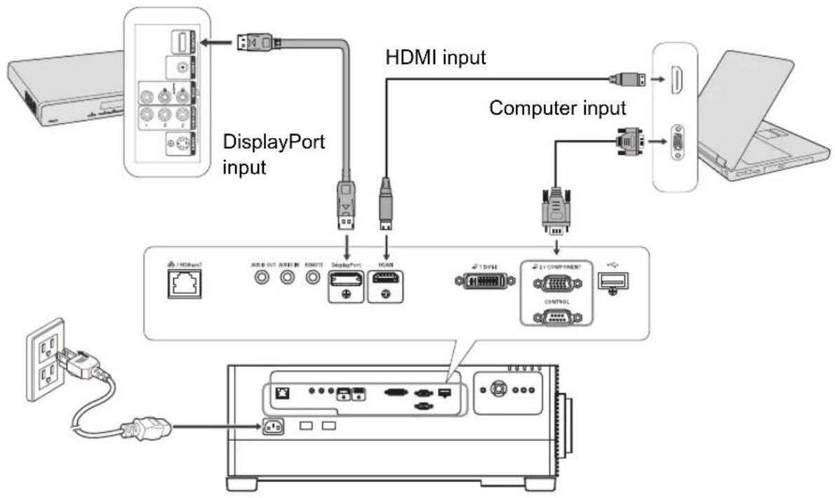
flowchart
graph TD
    A["Server"] --> B["DisplayPort input"]
    B --> C["HDMI input"]
    C --> D["Computer input"]
    D --> E["Laptop"]
    B --> F["DisplayPort"]
    B --> G["HDMI"]
    F --> H["1 HDMI"]
    G --> I["2 / COMPONENT"]
    H --> J["1 HDMI"]
    I --> K["2 / COMPONENT"]

When you connect a computer to the network, you will need to complete the IP address settings. For details, see "Configuring the Computer's Network Settings" (P84).
Step 2 Turn the Projector On
1Press the POWER button.
Remote control
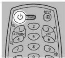
Projector
2Turn on the computer or other equipment.
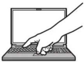
natural_image
Line drawing of a hand pressing on a laptop keyboard (no text or symbols)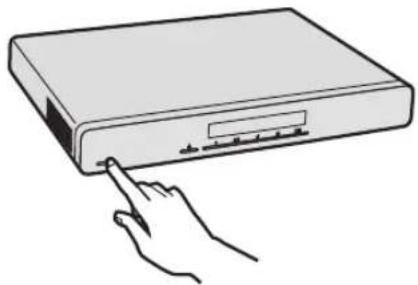
natural_image
Line drawing of a hand pressing a button on a device (no text or symbols)
- If a window is projected for menu language selection, use the pointer buttons to choose a language, and then press the OK button.
- If you have set a password, the password input screen appears. Enter your password (P165, P166).
- When "No signal" appears, press the INPUT button to select the input signal.
- If a computer screen is not projected, adjust the display settings on the computer. For details about how to switch display output, refer to the manual for your computer.
Step 3 Select an Input Signal
To switch between signals from connected devices, select an input signal in the [Input] menu.
The selected signal changes each time you press the INPUT button, or each time you press the [▲/ [ ]▼buttons when the [Input] window is shown.
The currently active input signal is marked with a green circle and enclosed by a orange border.
Names of input signals available for projection are displayed in white, and unavailable signal names are grayed out.
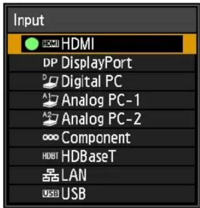
In single-image mode
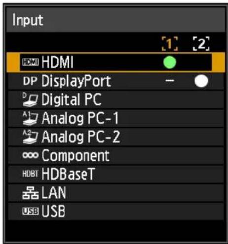
In split-screen mode

- [Digital PC] and [Analog PC-1] may be grayed out even when available.
- Screens of computers connected to the projector over a network can be projected when you have selected [LAN] as the input signal. For details, refer to the NMPJ user's manual.
- Images on USB flash drives can be projected when you have selected [USB] as the input signal. For details, see “Projecting Images on a USB Flash Drive” (P54).
- In split-screen mode, the side without control rights is identified by a white circle.
- Input signals can also be selected by using the INPUT A-C buttons on the remote control, depending on settings. For details, see "[INPUT A-C] button settings" (P160).
Step 4 Adjust the Image
■ Adjusting the Computer's Output Resolution
The projector's maximum resolution is 1920x1200 (P214).
For details on adjusting your computer's output resolution, refer to the manual for your computer.
■ Focusing / Resizing the Image
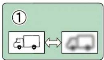
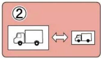
Press the ZOOM button on the remote control to adjust the image size, and press the FOCUS button to adjust the focus. You can also press the LENS button on the projector once to adjust focus and twice to adjust image size.
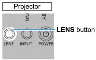
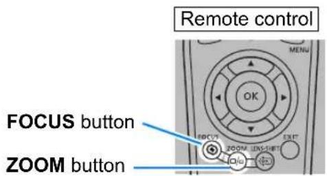
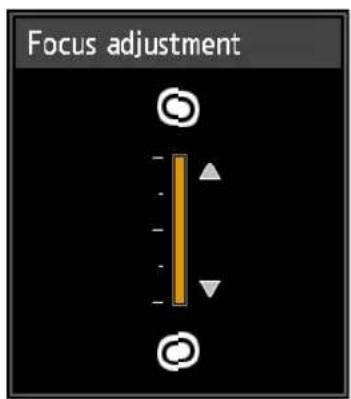
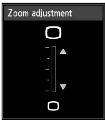
Focus adjustment Zoom adjustment
flowchart
graph LR
    A["Truck"] <--> B(Van)
flowchart
graph LR
    A["Truck 1"] <--> B["Truck 2"]

- Use the Auto PC function to adjust shift in computer image or the flickering of the screen (P127).
- Correct any keystone distortion by pressing the KEYSTONE button (P101).
- Select the screen aspect or projection aspect according to the aspect ratio of the screen, type of input image signal etc. (P97 – P99).
- Select an image mode depending on the projected image.
Step 5 Select the Image Quality (Image Mode)
Pressing the IMAGE button on the remote control, you can select an image mode to suit the projected image.
In each image mode, you can further adjust the brightness, contrast, sharpness, gamma, color adjustment, advanced adjustment, and lamp mode.
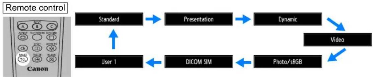
flowchart
graph TD
    A["Standard"] --> B["Presentation"]
    B --> C["Dynamic"]
    C --> D["Video"]
    E["User 1"] --> F["DICOM SIM"]
    F --> G["Photo/sRGB"]
    G --> D
    style A fill:#f9f,stroke:#333
    style B fill:#ccf,stroke:#333
    style C fill:#cfc,stroke:#333
    style D fill:#fcc,stroke:#333
    style E fill:#ffc,stroke:#333
    style F fill:#cfc,stroke:#333
    style G fill:#fcc,stroke:#333
■ Image Modes
| Image mode | Details |
| (1) Ambient Brightness(2) Types of Images(3) Effect on Projection | |
| Standard | (1) Bright(2) Computer screens, or media played with video software(3) Whites and natural colors |
| Presentation | (1) Bright(2) Images mainly consisting of text(3) Keeps the screen bright |
| Dynamic | (1) Bright(2) Media played with video software(3) Keeps the screen bright |
| Video | (1) Somewhat dark(2) Video from camcorders(3) Close to the color space of TVs |
| Photo/sRGB | (1) Somewhat dark(2) Digital photos from sRGB-compatible cameras(3) Conforms to the sRGB standard |
| DICOM SIM | (1) Somewhat dark(2) Monochrome images (medical use, for example)(3) Adjusted to the GSDF curve specified in DICOM Standard Part 14 |
| User 1 – 5 | Up to 5 user-selected combinations of image quality settings can be stored in the memory (P135). Stored settings can be selected as an image mode. |
■ Projecting an Image in the DICOM SIM Mode
In the DICOM simulation mode (hereinafter referred to as “DICOM SIM”), this projector can project a monochrome medical image such as an X ray radiography, CT image, MRI image, etc. in the tone similar to the DICOM (Digital Imaging and Communications in Medicine) standard. Typically, to project the image according to the DICOM standard, it requires the grayscale tone correction using a luminance meter according to the environment. In this projector, there are 21 types of tone settings for various ambient lights. You can correct the tone in a simplified manner by selecting the DICOM test pattern (P105).
It is suited to project an image in a medical lecture, academic conference, in-hospital conference, etc.
This projector is not the display monitor for a medical image. It cannot be used for the radiological image reading or medical examination.

- It is recommended to check the tone every time when using this projector since it does not have the tone correction and calibration functions against the secular change.
- It may take approximately 30 minutes until the projection brightness of this projector becomes stabled.
Switching the mode to the DICOM SIM Mode
1 Press the IMAGE button on the remote control until [DICOM SIM] is displayed or select [DICOM SIM] from [Image mode] in the [Image adjustment] menu.

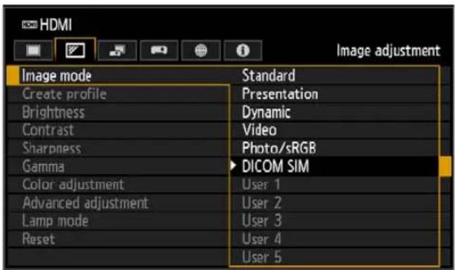
2Display test patterns by pressing the TEST PATTERN button on the remote control or selecting [On] in [Test pattern] of the [Install settings] menu. Press the [A/ [ ]buttons to select the DICOM test pattern.
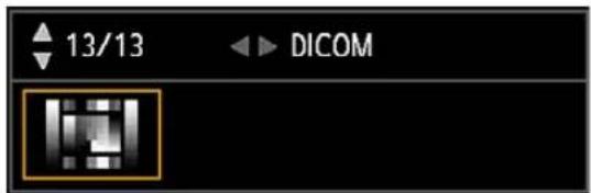
3 As you view the test pattern, perform [Gamma] (P136) adjustment from the [Image adjustment] menu until the image is optimal.
4Press the OK button after the setting.

Perform one of the followings to obtain an appropriate projection:
• Darken the ambient light
- Reduce the image size
- Reduce the projection distance
Turn the Projector Off
1 Press the POWER button.
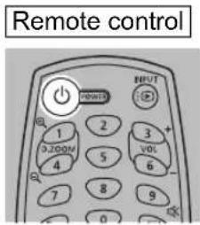
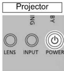
2When this window is displayed, press the POWER button again.
After you turn the power off, the projector will enter standby mode once it cools down.
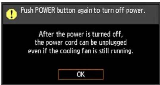

- If you want to continue projecting without turning off the power, press a button other than POWER, or else wait until the confirmation message disappears.
• After turning off the projector, wait at least 5 minutes before turning it on again. It may shorten the lamp life if you turn on the projector immediately after turning it off. - Using the projector for extended periods may shorten the life of the lamp and internal optical components.
- Unplug the projector if it will not be used for an extended period. Note that the [Date and time] setting will be reset, so you will need to set it again.
- In power management mode, the projector may go off automatically after some time (P162).
Convenient Projection Features
Convenient Features
This section describes convenient features during presentations and in other situations.
Temporarily Blacking Out an Image
Projection can be temporarily blanked after a presentation, or to divert the audience's attention away from the screen.
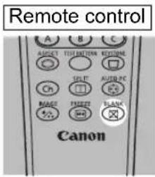
Press the BLANK button on the remote control to black out the image.
Press the BLANK button again to show the image.
- You can set the screen state while blacking out the image in the menu (P154).
- The lamp remains illuminated while the image is blacked out.
Freezing the Picture
Projection can be temporarily frozen during computer operations that would be distracting, or to pause playback of video or animation.
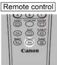
Press the FREEZE button on the remote control to freeze the moving image. The following icon appears. Press the FREEZE button again to return to the original display.
- It is also cancelled when the input signal is terminated.
Projecting a Test Pattern from the Menu
Even without any input signals, the projector can project a test pattern. Test patterns can be projected during installation to check how the projector is installed. For details on projecting test patterns, see “Test pattern” (P152) or “Adjustment Using a Test Pattern” (P105).
Specifying Power-Saving Settings
Set power-saving settings as needed.
The following four settings are available. For details, refer to the page describing each function.
- Lamp mode (P141)
Adjust lamp and fan power consumption in the image mode.
- Standby power settings (P162)
Conserves energy in standby mode by disabling some network functions.
• Power management mode (P162)
Automatically turns off the lamp or the power after a certain period if the projector is idle without an input signal.
• Power management duration (P163)
Specify the period after which the lamp or the projector should go off automatically if left idle without an input signal when [Power management mode] is set to [Light source off] or [Standby].
Adjusting the Volume
Useful when:
- You want to adjust the volume level of the projector or external speakers.
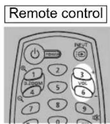
Press the VOL button. The following screen appears.
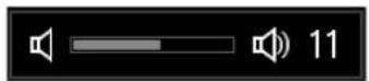
- You can also adjust the volume level with the [ ]◀ [ ] ▶buttons of the projector.
- Adjust the volume or mute setting on the computer if the volume level is too low.
- You can also adjust the volume level of the speakers connected via the audio output terminal.
Muting the Sound
Useful when:
- You want to temporarily mute unnecessary sound.
- You want to immediately mute the sound.
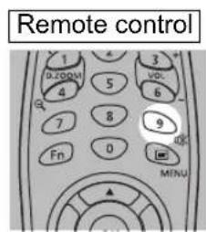
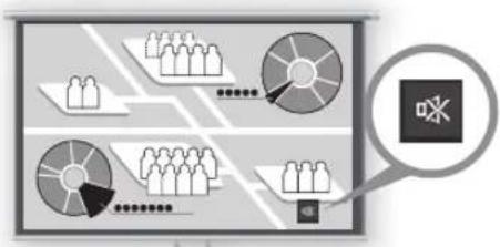
Press the MUTE button on the remote control to mute the sound. The following icon appears.
flowchart
graph TD
    A["User Group 1"] --> B["Shopping Cart"]
    C["User Group 2"] --> B
    D["User Group 3"] --> B
    E["User Group 4"] --> B
    F["User Group 5"] --> B
    G["User Group 6"] --> B
    H["User Group 7"] --> B
    I["User Group 8"] --> B
    J["User Group 9"] --> B
    K["User Group 10"] --> B
    L["User Group 11"] --> B
    M["User Group 12"] --> B
    N["User Group 13"] --> B
    O["User Group 14"] --> B
    P["User Group 15"] --> B
    Q["User Group 16"] --> B
    R["User Group 17"] --> B
    S["User Group 18"] --> B
    T["User Group 19"] --> B
    U["User Group 20"] --> B
    V["User Group 21"] --> B
    W["User Group 22"] --> B
    X["User Group 23"] --> B
    Y["User Group 24"] --> B
    Z["User Group 25"] --> B
    AA["User Group 26"] --> B
    AB["User Group 27"] --> B
    AC["User Group 28"] --> B
    AD["User Group 29"] --> B
    AE["User Group 30"] --> B
    AF["User Group 31"] --> B
    AG["User Group 32"] --> B
    AH["User Group 33"] --> B
    AI["User Group 34"] --> B
    AJ["User Group 35"] --> B
    AK["User Group 36"] --> B
    AL["User Group 37"] --> B
    AM["User Group 38"] --> B
    AN["User Group 39"] --> B
    AO["User Group 40"] --> B
    AP["User Group 41"] --> B
    AQ["User Group 42"] --> B
    AR["User Group 43"] --> B
    AS["User Group 44"] --> B
    AT["User Group 45"] --> B
    AU["User Group 46"] --> B
    AV["User Group 47"] --> B
    AW["User Group 48"] --> B
    AX["User Group 49"] --> B
    AY["User Group 50"] --> B
Screen
Press the MUTE button again to cancel the mute function.
- You can also mute the sound of the speakers connected via the audio output terminal.
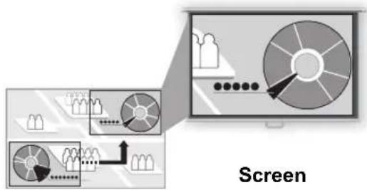
Zooming Part of an Image
Useful when:
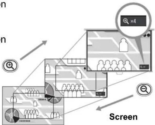
- Zooming in on an object such as a small graph during a presentation (up to 12x).
- Focusing on the current subject.
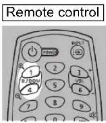
Press the +D.ZOOM button on the remote control to enlarge a part of the image. Press the -D.ZOOM button to reduce the image size.
• The magnification appears on the screen.
flowchart
graph TD
    A["User"] --> B["Search"]
    B --> C["Screen"]
    C --> D["User"]
    style A fill:#f9f,stroke:#333
    style B fill:#ccf,stroke:#333
    style C fill:#cfc,stroke:#333
    style D fill:#fcc,stroke:#333
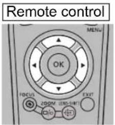
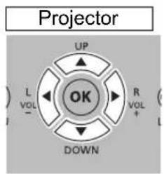
You can move the enlarged area by using the [▲] / [▼] / [ ] buttons.
flowchart
graph TD
    A["User Interaction"] --> B{Decision}
    B -->|Yes| C["Process Step"]
    B -->|No| D["End"]
    C --> E["Screen"]
    D --> E
    style A fill:#f9f,stroke:#333
    style E fill:#bbf,stroke:#333
You can restore the original size of the image by pressing the OK button.

The D.ZOOM buttons work differently than [Zoom] in the [Install settings] menu (P144).
Projecting Images on a USB Flash Drive
JPEG images stored on a USB flash drive connected to the projector can be projected. Individual images can be selected for projection, or you can project all images in a slideshow.
JPEG images up to 10912x8640 can be projected.
1 Insert a USB flash drive in the USB port.
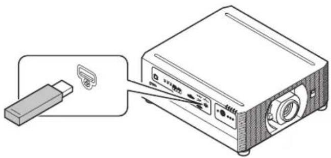
natural_image
Diagram of a projector connected to a small electronic device (no text or symbols visible)2Press the INPUT button to select [USB].
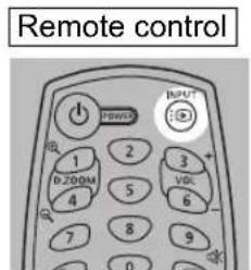
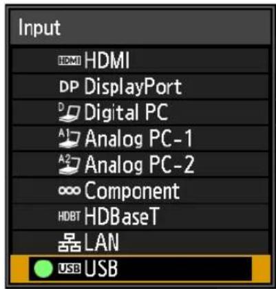
3In the USB file browser, select a file for projection. For details on the USB file browser, see "Description of USB File Browser" (P55), and for details on choosing files, see "Selecting an Image for Projection" (P57).
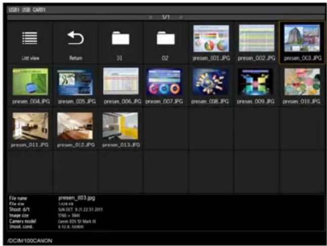

A USB card reader can also be used in the USB port.
Ending Projection
Remove the USB flash drive.

- USB flash drives with security features are not recognized by the projector and cannot be selected as the image source.
- If the projector cannot mount the file system, the drive name is grayed out and the following icon is displayed. In this case, the USB flash drive cannot be used.
! USB1 USB CARD1
- Up to six USB flash drives, 999 folders, or 9,999 files can be displayed.
- If there are multiple drives, a drive selection screen is displayed. Use the [▲] ▼ [ ] buttons to select the desired drive, and then press the OK button. Files on the drive are now listed.
- On file and drive selection screens, you can switch between thumbnail and list display.
- Network input is not available when [USB] is selected as the other input signal in split-screen display.
- Motion blur reduction is not available when projecting JPEG files on a USB flash drive (P163).
- The projector can also play a slideshow of images on a USB flash drive automatically (P57).
■ Description of USB File Browser
When a USB flash drive is connected to the projector, the USB file browser appears.
In the USB file browser, you can select the image file to be projected by operating the file list in the USB flash drive.
Thumbnail view List view
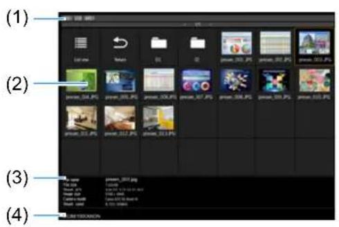
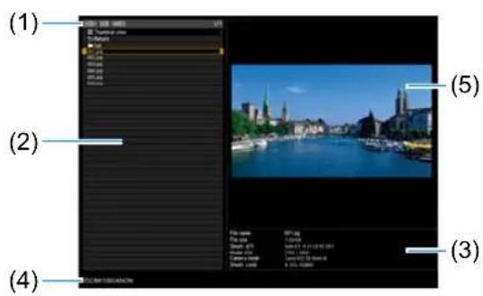
(1) List title
Identifies the current USB flash drive and number of pages in the file list displayed (Current page number/total number of pages).
(2) Drive/file list
Lists recognized USB flash drives and files in folders on the drive, by name. Select an image file or folder with the pointer buttons. The following icons are shown.
| Icon Function Icon Function | |||
 | Recognized USB flash drive (in thumbnail view) |  | Switch to list view (in thumbnail view) |
 | Correctly displayed USB flash drive (in list view) |  | Switch to thumbnail view (in list view) |
 | Unrecognized USB flash drive (in thumbnail view) |  | Go to the parent folder |
 | Unrecognized USB flash drive (in list view) |  | Folder |
 | No removable media in the card reader or similar device (in thumbnail view) |  | Unsupported JPEG file (in thumbnail view) |
 | No removable media in the card reader or similar device (in list view) | ||

File or folder names in Arabic are not displayed correctly.
(3) File information area
Information of the image selected in the file list appears here.
- File name
- File size
- Shoot. d/t
- Image size
- Camera model
- Shoot. cond.
(4) File path area
Path name of the image selected in the file list appears here.
(5) Preview area (in list view)
Image selected in the Drive/file list appears with reduced size. ? displayed when an unsupported JPEG format is selected.
If a folder is currently selected, the folder icon appears.
■ Selecting an Image for Projection
This section describes the steps for selecting an image in the USB file browser and projecting on the screen.
Selecting a Drive
This step may not be necessary when a USB flash drive is connected directly to the projector's USB port.
If a USB memory card reader having multiple memory slots is connected, the drive (memory slot) list is displayed in the file list.
Select the drive in which the memory card is inserted with [▲/ [ ], and press the OK button.
• Active drives are displayed in white text, while inactive drives are grayed out.
Selecting a Folder
Folders that contain images can be selected.
- To return to the higher level, select

Selecting an Image File for Projection
In list view, when you select an image file, a small preview of the image is shown in the preview area.
For full-screen projection of the image, press the OK button.
To return to the higher level, select

Changing the View
To switch the view, select [Thumbnail view] or [List view] in the Drive/file list and press the OK button.
■ Controlling Images in Full-Screen Projection
When images are projected, you can perform the following operations.
Project the previous or next image by pressing the [▲/ [ ]▼buttons.
Rotate images left or right 90° by pressing the [◀] / [ ] buttons.
Return to the USB file browser by pressing the OK button.
- These operations are also available during slideshows. (Except when [Animation effect] is enabled.)
- If the image contains rotational information, the image is rotated to an appropriate direction automatically.
■ Running a Slideshow of Data Saved in a USB Flash Drive
Multiple images on a USB flash drive can be projected consecutively, with each shown for a specific interval.
Setting a Slideshow Interval
Set the projection interval in [Slideshow interval] (P130) in the menu.
Projecting Two Images Side by Side
Images from two connected devices can be projected side by side. This is split-screen display. When you activate split-screen display, the current image is shown on the left side, and the new image is shown at right. You can change the source of images shown on each side by pressing the INPUT button.
Supply two signals to the projector.
You can combine the following input in split-screen display.
Note that split-screen display is not
available for some combinations of input signals.
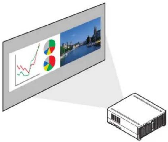
Split-Screen Combinations
○ : Can be combined
○*: Can be combined (50:50 display)
—: Cannot be combined
To start split-screen display, press the SPLIT button on the remote control.
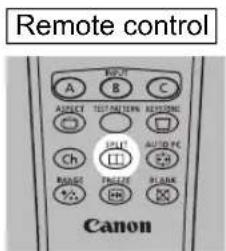
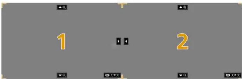
A number is displayed in the center of one image area. The left image is "1," and the right image, "2." The image labeled with a number has "control rights," and the sound for that image will be played.
■ Switching Input Signals
If or is displayed in the center of the image area, you can switch control rights to the other side by using the [◀] / [ ] buttons on the remote control.
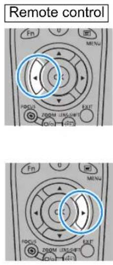
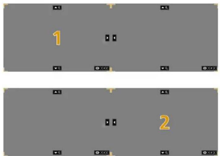
Press the INPUT button, and then select the input signal for the side with control rights.
To determine which side is currently under your control, check the image ID in orange in the upper right of the menu.
The side without control rights is labeled with a white circle.
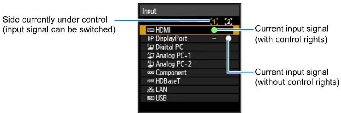

- Display of the centered number fades in a while, but you can view it again by pressing the SPLIT button on the remote control.
- To exit split-screen display, press the EXIT button on the remote control.
- You can also switch to split-screen display by selecting [Split screen] in the [Input settings] menu (P132).
- Some functions cannot be adjusted, such as [Sharpness] (P136), [Dynamic gamma] (P138), and [Motion blur reduction] (P163).
- Some functions are not available, such as [Image flip H/V] (P143), [Screen aspect] (P144), [Keystone] (P145) and [Logo capture] (P154).
- For split-screen image adjustment, use the [Image priority] setting (P141).
- Image mode colors differ somewhat from those in single-image mode.
Installation Guide
Before setting up the projector, be sure to read "Before Installation" (P24).
Relationship Between Projecting Distance and Image Size
The projected image size is determined by the distance between the projector and the screen (projection distance) as well as the zoom. Refer to the following table and decide the distance between the projector and screen.
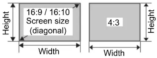
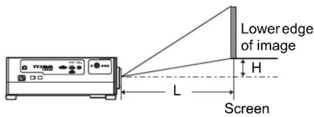
L: Projection distance
H: Height from center of lens to lower edge of image
At a screen aspect of 16:10
| Lens unit RS-SL | L01ST RS-SL02 | LZ RS-SL04UL | RS-SL05WZ | Height H**[cm] | |||||||
| Projection ratio* 1.49 - 2.24:1 2.19 | -3.74:1 3.55 - | 6.94:1 1.00 - 1.50:1 | RS-SL01STRS-SL02LZRS-SL04ULRS-SL05WZ | ||||||||
| Diagonal | Image size[cm] | Projection distance L [m (feet)] | |||||||||
| Width | Height | Wide limit | Tele limit | Wide limit | Tele limit | Wide limit | Tele limit | Wide limit | Tele limit | ||
| 40 86 | 54 | 1.3(4.3) | 1.9(6.2) | 1.9(6.2) | 3.2(10.5) | — | — | 0.9(3.0) | 1.3(4.3) | -35.0 - +2.7 | |
| 60 | 129 | 81 | 1.9(6.2) | 2.9(9.5) | 2.8(9.2) | 4.8(15.7) | 4.6(15.1) | 9.0(29.5) | 1.3(4.3) | 1.9(6.2) | -52.5 - +4.0 |
| 80 17 | 2 108 | 2.6(8.5) | 3.9(12.8) | 3.8(12.5) | 6.4(21.0) | 6.1(20.0) | 12.0(39.3) | 1.7(5.6) | 2.6(8.5) | -70.0 - +5.4 | |
| 100 | 215 | 135 | 3.2(10.5) | 4.8(15.7) | 4.7(15.4) | 8.0(26.3) | 7.6(24.9) | 14.9(48.9) | 2.2(7.2) | 3.2(10.5) | -87.5 - +6.7 |
| 150 3 | 23 202 | 4.8(15.7) | 7.2(23.6) | 7.1(23.3) | 12.1(39.7) | 11.4(37.4) | 22.3(73.2) | 3.2(10.5) | 4.9(16.1) | -131 - +10.1 | |
| 200 | 431 | 269 | 6.4(21.0) | 9.6(31.5) | 9.5(31.2) | 16.1(52.8) | 15.2(49.9) | 29.8(97.8) | 4.3(14.1) | 6.5(21.3) | -175 - +13.5 |
| 250 5 | 38 337 | 8.0(26.2) | 12.1(39.7) | 11.9(39.0) | 20.2(66.3) | 18.9(62.0) | 37.2(122.0) | 5.4(17.7) | 8.1(26.6) | -219 - +16.8 | |
| 300 | 646 | 404 | 9.6(31.5) | 14.5(47.6) | 14.2(46.6) | 24.2(79.4) | 22.7(74.5) | 44.6(146.3) | 6.5(21.3) | 9.7(31.8) | -263 - +20.2 |
| 350 7 | 54 471 | 11.3(37.1) | 16.9(55.4) | 16.6(54.5) | 28.3(92.8) | 26.4(86.6) | 52.0(170.6) | 7.5(24.6) | 11.4(37.4) | -306 - +23.6 | |
| 400 | 862 | 538 | 12.9(42.3) | 19.3(63.3) | 19.0(62.3) | 32.3(106.0) | 30.2(99.1) | 59.4(194.9) | 8.6(28.2) | 13.0(42.7) | -350 - +26.9 |
| 450 9 | 69 606 | 14.5(47.6) | 21.7(71.2) | 21.4(70.2) | 36.4(119.4) | 34.0(111.5) | 66.8(219.2) | 9.7(31.8) | 14.6(47.9) | -394 - +30.3 | |
| 500 | 1077 | 673 | 16.1(52.8) | 24.1(79.1) | 23.8(78.1) | 40.4(132.5) | 37.7(123.7) | 74.2(243.4) | 10.8(35.4) | 16.3(53.5) | -438 - +33.7 |
| 550 1 | 185 740 | 17.7(58.1) | 26.6(87.3) | 26.1(85.6) | 44.5(146.0) | 41.5(136.2) | 81.6(267.7) | 11.8(38.7) | 17.9(58.7) | -481 - +37.0 | |
| 600 | 1292 | 808 | 19.3(63.3) | 29.0(95.1) | 28.5(93.5) | 48.5(159.1) | 45.2(148.3) | 89.0(292.0) | 12.9(42.3) | 19.5(64.0) | -525 - +40.4 |
| Lens unit RS-SL03WF RS-SL06UW Height H** [cm] | ||||||
| Projection ratio* 0.80:1 0.54:1 | RS-SL03WF RS-SL06UW | |||||
| Diagonal | Image size [cm] | Projection distance L[m (feet)] | ||||
| Width Height | ||||||
| 40 | 86 | 54 | 0.69 (2.3) | 0.45 (1.5) | -33.0 - -20.8 | -35.0 - +13.5 |
| 60 129 | 81 | 1.04 (3.4) | 0.69 (2.3) -49 | .5 - -31.3 -52 | .5 - +20.2 | |
| 80 | 172 | 108 | 1.38 (4.5) | 0.92 (3.0) | -66.0 - -41.7 | -70.0 - +26.9 |
| 100 | 215 | 135 | 1.73 (5.7) | 1.16 (3.8) | -82.5 - -52.1 | -87.5 - +33.7 |
| 150 | 323 | 202 | 2.59 (8.5) | 1.75 (5.7) | -123 - -78.1 | -131 - +50.5 |
| 200 | 431 | 269 | 3.45 (11.3) | 2.33 (7.3) | -165 - -104 | -175 - +67.3 |
| 250 | 538 | 337 | 4.31 (14.1) | 2.92 (9.6) | -206 - -130 | -219 - +84.1 |
| 300 | 646 | 404 | 5.17 (17.0) | 3.51 (11.5) | -248 - -156 | -263 - +101 |
* Projection ratios are based on projection to 100-inch screens.
** Height (H) is based on [Normal] lens shift mode.
For details on the image position in [Expanded] mode, see "Adjustment Using Lens Shift" (P70).
At a screen aspect of 16:9
| Lens unit | RS-SL01ST | RS-SL02LZ | RS-SL04UL | RS-SL05WZ | Height H**[cm] | ||||||
| Projection ratio* | 1.53 – 2.30:1 | 2.25 – 3.84:1 | 3.65 – 7.13:1 | 1.03 – 1.54:1 | RS-SL01STRS-SL02LZRS-SL04ULRS-SL05WZ | ||||||
| Diagonal | Image size (cm) | Projection distance L [m (feet)] | |||||||||
| Width | Height | Wide limit | Tele limit | Wide limit | Tele limit | Wide limit | Tele limit | Wide limit | Tele limit | ||
| 40 | 89 | 50 | 1.3(4.3) | 2.0(6.6) | 1.9(6.2) | 3.3(10.8) | — | — | 0.9(3.0) | 1.3(4.3) | -33.2 – +5.5 |
| 60 | 133 | 75 | 2.0(6.7) | 3.0(9.8) | 2.9(9.5) | 4.9(16.1) | 4.8(15.7) | 9.3(30.5) | 1.3(4.3) | 2.0(6.6) | -49.8 – +8.3 |
| 80 | 177 | 100 | 2.6(8.5) | 4.0(13.1) | 3.9(12.8) | 6.6(21.7) | 6.3(20.7) | 12.3(40.4) | 1.8(5.9) | 2.7(8.9) | -66.4 – +11.1 |
| 100 | 221 | 125 | 3.3(10.8) | 5.0(16.4) | 4.9(16.1) | 8.3(27.2) | 7.9(25.9) | 15.4(50.5) | 2.2(7.2) | 3.3(10.8) | -83.0 – +13.8 |
| 150 | 332 | 187 | 5.0(16.4) | 7.4(24.3) | 7.3(24.0) | 12.4(40.7) | 11.7(38.4) | 23.0(75.5) | 3.3(10.8) | 5.0(16.4) | -125 – +20.8 |
| 200 | 443 | 249 | 6.6(21.7) | 9.9(32.5) | 9.7(31.8) | 16.6(54.5) | 15.6(51.2) | 30.6(100.4) | 4.4(14.4) | 6.7(22.0) | -166 – +27.7 |
| 250 | 553 | 311 | 8.3(27.2) | 12.4(40.7) | 12.2(40.0) | 20.7(67.9) | 19.4(63.6) | 38.2(125.3) | 5.5(18.0) | 8.3(27.2) | -208 – +34.6 |
| 300 | 664 | 374 | 9.9(32.5) | 14.9(48.9) | 14.6(47.9) | 24.9(81.7) | 23.3(76.4) | 45.8(150.3) | 6.6(21.7) | 10.0(32.8) | -249 – +41.5 |
| 350 | 775 | 436 | 11.6(38.1) | 17.4(57.1) | 17.1(56.1) | 29.1(95.5) | 27.2(89.2) | 53.4(175.2) | 7.7(25.3) | 11.7(38.4) | -291 – +48.4 |
| 400 | 886 | 498 | 13.2(43.3) | 19.9(65.3) | 19.5(64.0) | 33.2(108.9) | 31.0(101.7) | 61.0(200.1) | 8.9(29.2) | 13.4(44.0) | -332 – +55.3 |
| 450 | 996 | 560 | 14.9(48.9) | 22.3(73.2) | 22.0(72.2) | 37.4(122.7) | 34.9(114.5) | 68.6(225.1) | 10.0(32.8) | 15.0(48.2) | -374 – +62.3 |
| 500 | 1107 | 623 | 16.5(54.1) | 24.8(81.4) | 24.4(80.1) | 41.5(136.2) | 38.8(127.3) | 76.3(250.3) | 11.1(36.4) | 16.7(54.8) | -415 – +69.2 |
| 550 | 1218 | 685 | 18.2(59.7) | 27.3(89.6) | 26.9(88.3) | 45.7(149.9) | 42.6(139.8) | 83.9(275.3) | 12.2(40.0) | 18.4(60.4) | -457 – +76.1 |
| 580 | 1284 | 722 | 19.2(63.0) | 28.8(94.5) | 28.3(92.8) | 48.2(158.1) | 44.9(147.3) | 88.4(290.0) | 12.8(42.0) | 19.4(63.6) | -482 – +80.3 |
| Lens unit RS-SL03WF RS-SL06UW Height H** [cm] | ||||||
| Projection ratio* 0.82:1 0.55:1 | RS-SL03WF RS-SL06UW | |||||
| Diagonal | Image size [cm] | Projection distance L[m (feet)] | ||||
| Width Height | ||||||
| 40 | 89 | 50 | 0.71 (2.3) | 0.48 (1.6) | -31.2 – -18.7 | -33.2 – +16.6 |
| 60 | 133 | 75 1.0 | 7 (3.5) 0.72 (2.4) | -46.7 – -28.0 | -49.8 – +24.9 | |
| 80 | 177 | 100 | 1.42 (4.7) | 0.96 (3.1) | -62.3 – -37.3 | -66.4 – +33.2 |
| 100 | 221 | 125 | 1.77 (5.8) | 1.20 (3.9) | -77.9 – -46.6 | -83.0 – +41.5 |
| 150 | 332 | 187 | 2.66 (8.7) | 1.79 (5.9) | -117 – -69.9 | -125 – +62.3 |
| 200 | 443 | 249 | 3.54 (11.6) | 2.39 (7.8) | -156 – -93.3 | -166 – +83.0 |
| 250 | 553 | 311 | 4.43 (14.5) | 2.99 (9.8) | -195 – -117 | -208 – +104 |
| 290 | 642 | 361 | 5.14 (16.9) | 3.47 (11.4) | -226 – -135 | -241 – +120 |
* Projection ratios are based on projection to 100-inch screens.
** Height (H) is based on [Normal] lens shift mode.
For details on the image position in [Expanded] mode, see "Adjustment Using Lens Shift" (P70).
At a screen aspect of 4:3
| Lens unit | RS-SL01ST | RS-SL02LZ | RS-SL04UL | RS-SL05WZ | Height H**[cm] | ||||||
| Projection ratio* | 1.69 – 2.53:1 | 2.48 – 4.23:1 | 4.01 – 7.85:1 | 1.13 – 1.70:1 | RS-SL01STRS-SL02LZRS-SL04ULRS-SL05WZ | ||||||
| Diagonal | Image size[cm] | Projection distance L [m (feet)] | |||||||||
| Width | Height | Wide limit | Tele limit | Wide limit | Tele limit | Wide limit | Tele limit | Wide limit | Tele limit | ||
| 40 | 81 | 61 | 1.4(4.6) | 2.2(7.2) | 2.1(6.9) | 3.6(11.8) | — | — | 1.0(3.2) | 1.4(4.6) | -39.6 – +3.0 |
| 60 | 122 | 91 | 2.2(7.2) | 3.3(10.8) | 3.2(10.5) | 5.5(18.0) | 5.2(17.1) | 10.2(33.5) | 1.5(4.9) | 2.2(7.2) | -59.4 – +4.6 |
| 80 | 163 | 122 | 2.9(9.5) | 4.4(14.4) | 4.3(14.1) | 7.3(24.0) | 6.9(22.6) | 13.5(44.3) | 2.0(6.6) | 2.9(9.5) | -79.2 – +6.1 |
| 100 | 203 | 152 | 3.6(11.8) | 5.5(18.0) | 5.3(17.4) | 9.1(29.9) | 8.6(28.2) | 16.9(55.4) | 2.4(7.9) | 3.7(12.1) | -99.1 – +7.6 |
| 150 | 305 | 229 | 5.5(18.0) | 8.2(26.9) | 8.0(26.2) | 13.7(44.9) | 12.9(42.3) | 25.3(83.0) | 3.7(12.1) | 5.5(18.0) | -149 – +11.4 |
| 200 | 406 | 305 | 7.3(24.0) | 10.9(35.8) | 10.7(35.1) | 18.3(60.0) | 17.1(56.1) | 33.7(110.6) | 4.9(16.1) | 7.3(24.0) | -198 – +15.2 |
| 250 | 508 | 381 | 9.1(29.9) | 13.7(44.9) | 13.4(44.0) | 22.9(75.1) | 21.4(70.2) | 42.1(138.1) | 6.1(20.0) | 9.2(30.2) | -248 – +19.1 |
| 300 | 610 | 457 | 10.9(35.8) | 16.4(53.8) | 16.1(52.8) | 27.4(89.9) | 25.7(84.3) | 50.4(165.4) | 7.3(24.0) | 11.0(36.1) | -297 – +22.9 |
| 350 | 711 | 533 | 12.7(41.7) | 19.1(62.7) | 18.8(61.7) | 32.0(105.0) | 29.9(98.1) | 58.8(192.9) | 8.5(27.9) | 12.9(42.3) | -347 – +26.7 |
| 400 | 813 | 610 | 14.6(47.9) | 21.9(71.9) | 21.5(70.5) | 36.6(120.1) | 34.2(112.2) | 67.2(220.5) | 9.8(32.2) | 14.7(48.2) | -396 – +30.5 |
| 450 | 914 | 686 | 16.4(53.8) | 24.6(80.7) | 24.2(79.4) | 41.2(135.2) | 38.4(126.0) | 75.6(248.0) | 11.0(36.1) | 16.6(54.5) | -446 – +34.3 |
| 500 | 1016 | 762 | 18.2(59.7) | 27.3(89.6) | 26.9(88.3) | 45.8(150.3) | 42.7(140.1) | 84.0(275.6) | 12.2(40.0) | 18.4(60.4) | -495 – +38.1 |
| 530 | 1077 | 808 | 19.3(63.3) | 29.0(95.1) | 28.5(93.5) | 48.5(159.1) | 45.2(148.3) | 89.0(292.0) | 12.9(42.3) | 19.5(64.0) | -525 – +40.4 |
| Lens unit RS-SL03WF RS-SL06UW Height H** [cm] | ||||||
| Projection ratio* 0.91:1 0.61:1 | RS-SL03WF RS-SL06UW | |||||
| Diagonal | Image size [cm] | Projection distance L[m (feet)] | ||||
| Width Height | ||||||
| 40 | 81 | 61 | 0.78 (2.6) | 0.53 (1.7) | -37.4 – -23.6 | -39.6 – +15.2 |
| 60 122 | 91 | 1.17 (3.8) | 0.79 (2.6) -56 | 1 – -35.4 -59 | 4 – +22.9 | |
| 80 | 163 | 122 | 1.56 (5.1) | 1.05 (3.4) | -74.7 – -47.2 | -79.2 – +30.5 |
| 100 | 203 | 152 | 1.95 (6.4) | 1.32 (4.3) | -93.4 – -59.0 | -99.1 – +38.1 |
| 150 | 305 | 229 | 2.93 (9.6) | 1.97 (6.5) | -140 – -88.5 | -149 – +57.2 |
| 200 | 406 | 305 | 3.90 (12.8) | 2.63 (8.6) | -187 – -118 | -198 – +76.2 |
| 250 | 508 | 381 | 4.88 (16.0) | 3.29 (10.8) | -234 – -147 | -248 – +95.3 |
| 260 | 528 | 396 | 5.07 (16.6) | 3.42 (11.2) | -243 – -153 | -258 – +99.1 |
* Projection ratios are based on projection to 100-inch screens.
** Height (H) is based on [Normal] lens shift mode.
For details on the image position in [Expanded] mode, see "Adjustment Using Lens Shift" (P70).
Installing / Removing the Lens Unit
- Before installing or removing the lens unit, be sure to disconnect the power plug or connector. Failure to do so may result in fire, electric shock, or injury.
- When hanging the projector from a ceiling, put the projector down on the floor or a workbench before attaching or replacing the lens unit. Failure to do so could result in parts falling off the projector and may cause a malfunction or personal injury.
- The projector is provided with a lens shift function to move the lens up, down, left, and right using the motor. Do not touch the lens while it is moving. Touching the lens when it is moving may result in personal injury.
- Before replacing the lens unit, wait at least 30 minutes after the projector is turned off to allow the lens unit to cool down. Failure to do so may result in burns or injury.
- When installing and removing the lens unit, be sure not to touch the surface of the lens with your hands or scratch it.
- Do not apply force to parts (e.g. lead wires) that are connected to the lens unit or lens motor. Doing so may cause a malfunction.
- Do not replace the lens unit in a dusty location. If any dust or dirt enters the projector, this may adversely affect picture quality.
- When carrying or holding up the projector after attaching the lens unit, be sure not to hold the lens. Doing so may cause damage to the lens unit.
- If transportation is necessary, the lens unit should be removed before transporting the projector. If the projector is subjected to excessive impacts during transportation, the lens unit may be damaged.
- For details about which devices the projector is compatible with, contact the Canon Customer Support Center.

■ Installing the Lens Unit
1 After confirming that the lens lever is raised, hold the lens unit with the lens connector on the left side and insert it in the projector, keeping the lens connector aligned with the connector in the projector.
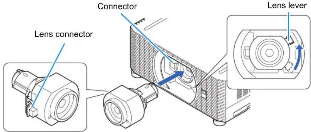

Keep the lens unit level as you insert it straight into the projector. Inserting it crooked may prevent the lens lever from moving freely or make projection blurry.
2Turn the lens lever clockwise to secure the lens unit.
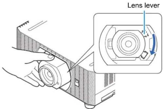

- When securing the lens unit, make sure it is fully inserted in the projector, and then turn the lens lever clockwise (toward the bottom, as shown) to secure it. If it is not fully inserted, this may prevent the lens lever from moving freely or make projection blurry.
- The projector stores certain information about lenses. This information must be set again when lenses are replaced. After lens replacement, lens shift reset is performed automatically when the projector is restarted. However, when reinstalling the same type of lens, perform lens shift reset manually (P151).
- Also refer to instructions included with the replacement lens.
Removing the Lens Unit
1 Raise the lens lever by turning it counterclockwise.
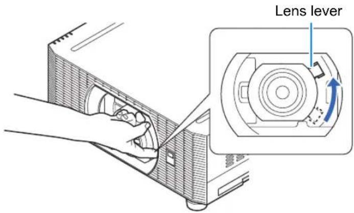
2Hold the lens unit securely as you remove it.

When removing the lens unit, keep it level as you pull it straight out of the projector.
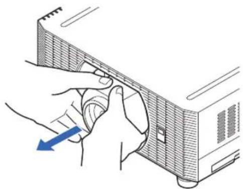
natural_image
Illustration of hands inserting a device into a rack (no text or symbols)Installation
Place the projector in front of the screen.

- To avoid keystone distortion, install the projector so that it is at right angles to the screen.
- The screen must not be exposed to direct sunlight or light from lighting equipment. In a bright room, it is recommended that lights be turned off, curtains be drawn, and other steps taken to make the screen easier to see.
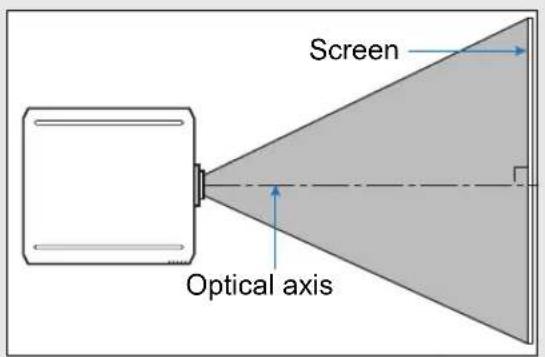
■ Tabletop or Floor Installation (Lower Than the Screen)
To adjust the projection position, use the lens shift function or the adjustable feet.
1 Press the LENS-SHIFT button on the remote control to display the lens shift adjustment window.
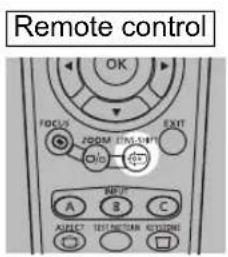
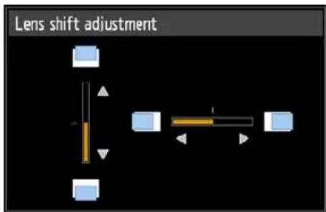
Press the LENS button on the projector repeatedly to switch between windows for parameters adjusted by controlling the lens.
To access the lens shift adjustment window, press the LENS button three times (or four times if you have set [Marginal focus] to [On]).
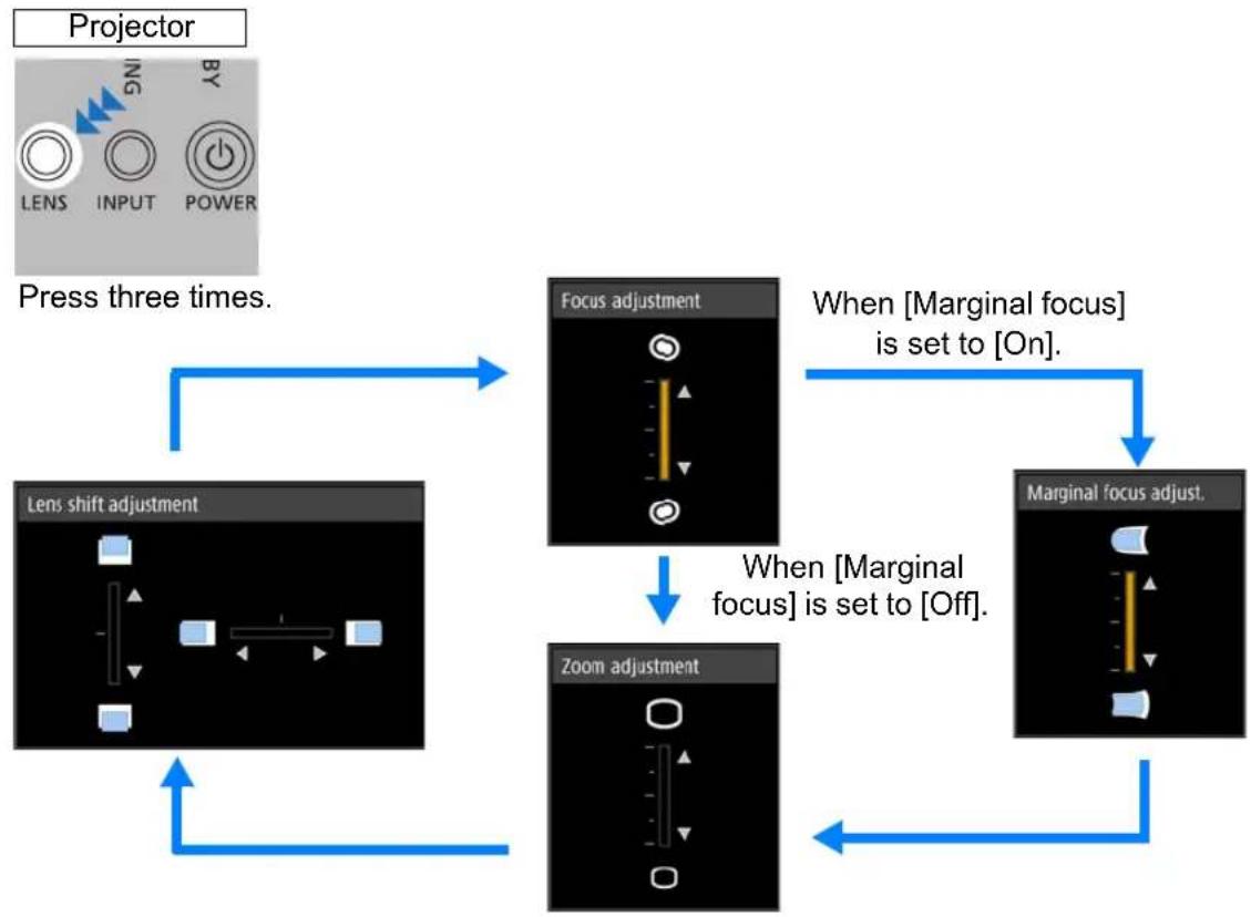
flowchart
graph TD
    A["Projector"] --> B["Press three times."]
    B --> C["Lens shift adjustment"]
    C --> D["Focus adjustment"]
    D --> E["Marginal focus adjust."]
    E --> F["Zoom adjustment"]
    F --> G["When [Marginal focus"] is_set_to["On"].]
    G --> H["When [Marginal focus"] is_set_to["Off"].]
    H --> I["Press three times."]
2Press the pointer buttons to adjust.
To raise or lower the image, use the [4] / [ ] buttons on the remote control or projector.
To move the image left or right, use the [◀] / [▶buttons on the remote control or projector.
To continue moving the image in a specific direction, hold down the corresponding button.
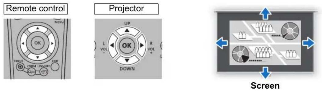
Adjustment Using Lens Shift
You can reposition the image in all directions by shifting the lens up, down, left, or right. This feature is referred to as lens shift. The projector's lens shift range is as follows.
Amount movable in up/down direction
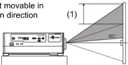
At maximum upward lens shift
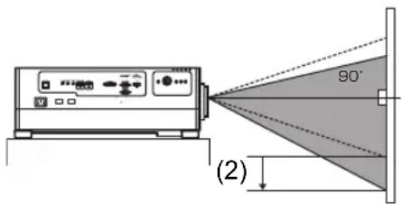
At maximum downward lens shift
Amount movable in left/right direction
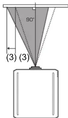
At maximum leftward lens shift
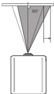
At maximum rightward lens shift
Amount of Lens Shift for Each Replacement Lens
| Lens unit Lens shift mode: Normal Lens shift mode: Expanded* | ||
| RS-SL01ST | Up (1) : +55%Down (2) : -15%Left/right (3) : ±10% | Up (1) : +90%Down (2) : -90%Left/right (3) : ±30% |
| RS-SL02LZ | ||
| RS-SL04UL | ||
| RS-SL05WZ | ||
| RS-SL03WF Up (1) : +11 | .3%Down (2) : -11.3%Left/right (3) : ±4.6% | |
| RS-SL06UW Up (1) : +75%Down (2) : -15%Left/right (3) : ±30% | ||
* Image quality may decrease in [Expanded] lens shift mode, depending on the extent of lens shift.

Before using this feature, connect the projector to a computer or AV equipment (P76) and plug the projector in (P80).
Area Outside the Lens Shift Range (in [Normal] Lens Shift Mode\*)
- Zoom Lenses: RS-SL01ST/RS-SL02LZ/RS-SL04UL/RS-SL05WZ
When the shift exceeds 44% in the upward direction, the amount of available shift in the left/right directions decreases. When the lens is shifted upward to the maximum of 55% (1), the lens cannot be shifted left or right.
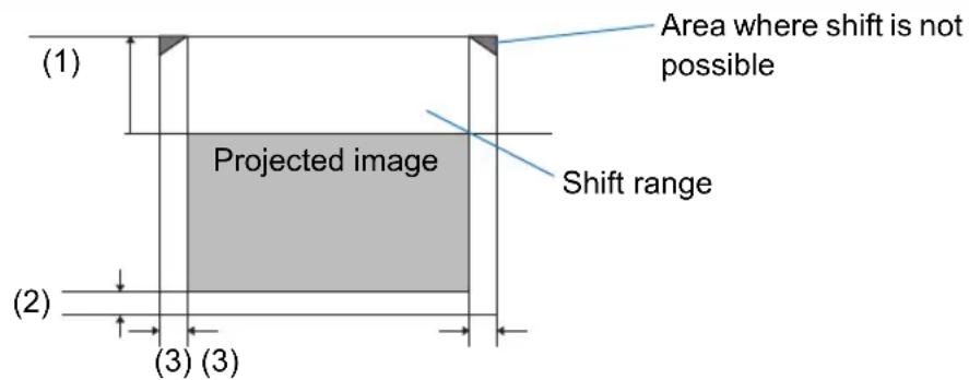
- Short Fixed Lens: RS-SL03WF
The more you shift the lens up or down, the less you can shift it left or right. When the lens is shifted upward or downward to the maximum of 11.3%, the lens cannot be shifted left or right.
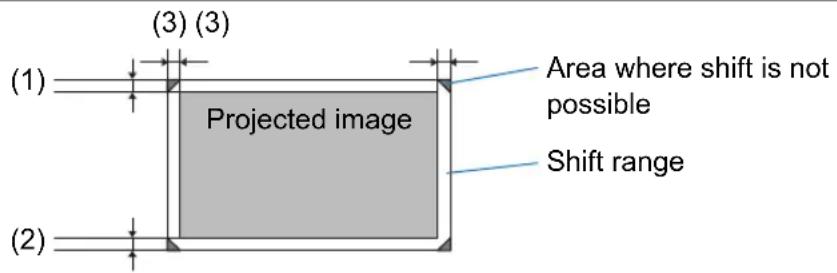
- Ultra-wide Zoom Lens: RS-SL06UW
The more you shift the lens up or down, the less you can shift it left or right. When the lens is shifted upward to the maximum of 75%, the lens cannot be shifted left or right.
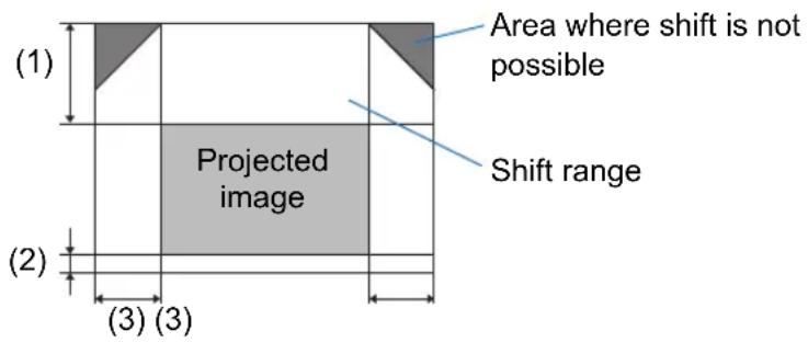
![CANON REALiS WUX6700 - Area Outside the Lens Shift Range (in [Normal] Lens Shift Mode\*) - 4](/content/2026/05/965391/images/717500221c2832f9ebd901cb069e6c6e1a37a5cba45b805f8cf632e75b9c428d.jpg)
In [Expanded] lens shift mode, the lens can be shifted to each corner position, however image quality may decrease.
Resetting the Position
During screen position adjustment, press and hold the LENS-SHIFT button on the remote control or the LENS button on the projector to display the [Lens shift reset] window. The selections for the lens currently used are displayed. Use the pointer buttons to select one of them, then press the OK button.
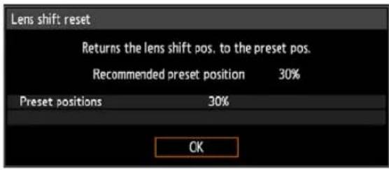
| Lens unit type Available items | |
| RS-SL01ST | 50%: Up 50%, left/right 0%0%: Up/down/left/right 0% |
| RS-SL02LZ | |
| RS-SL04UL | |
| RS-SL05WZ | |
| RS-SL03WF | 0%: Up/down/left/right 0% |
| RS-SL06UW | |

• After resetting, the lens may be slightly misaligned from your selected position.
- For precise positioning, use the lens shift function to fine-tune the position.
Adjusting Peripheral Focus
This feature enables focus adjustment around the edges of the screen.
- Use marginal focus adjustment for curved screens, such as domes.
- Use marginal focus adjustment to bring images on flat screens into focus if image edges remain warped after you adjust the overall focus.

- The marginal focus feature is not available depending on the type of lens installed.
• [Marginal focus] must be set to [On] in advance (P147).
■ Bringing Image Edges into Focus
To adjust peripheral focus, press the FOCUS button on the remote control or the LENS button on the projector.
1 Press the FOCUS button on the remote control twice to display the marginal focus adjustment window.
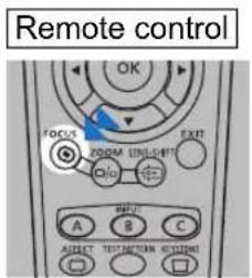
Press twice.
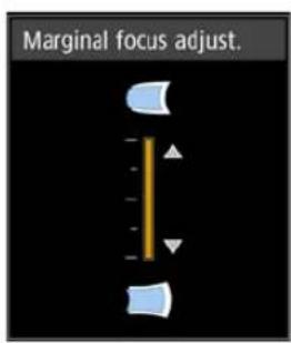
Installation Procedure
Pressing the LENS button on the projector repeatedly switches between windows for lens-related parameters.
Press the LENS button twice to display the marginal focus adjustment window.
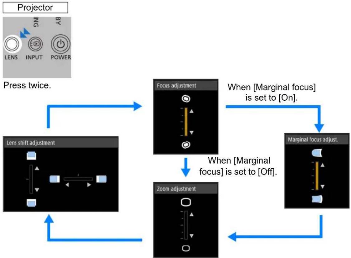
flowchart
graph TD
    A["Projector"] --> B["Press twice."]
    B --> C["Lens shift adjustment"]
    C --> D["Focus adjustment"]
    D --> E["Marginal focus adjust."]
    E --> F["Zoom adjustment"]
    F --> G["When [Marginal focus"] is_set_to["On"].]
    G --> H["Marginal focus adjust."]
    H --> I["When [Marginal focus"] is_set_to["Off"].]
    I --> J["Lens shift adjustment"]
    J --> K["Focus adjustment"]
    K --> L["Zoom adjustment"]
    L --> M["When [Marginal focus"] is_set_to["On"].]
    M --> N["Marginal focus adjust."]
2Press the pointer buttons to adjust the focus at image edges.
Press the [▲/ [ ]▶[ ] /▼] buttons to adjust peripheral focus.
Installation Procedure
The focus at the center of the screen may become blurred when the indicator is moved to nearly to the top or bottom edge in the [Marginal focus adjust.] window. If this happens, perform steps (1) to (3) below repeatedly to adjust the focus of the entire screen.
(1) Use [Focus adjustment] (P46) to adjust the focus at the center of the screen.
(2) Use [Marginal focus adjust.] to adjust the focus at the edges of the screen.
(3) Check the focus at the center of the screen.

When using the lens shift adjustment function, the optical axis may be shifted further from the center of the screen than when the function is not used. This can be adjusted by performing steps (1) to (3) repeatedly.
3Once image edges are in focus, press the OK or FOCUS button.
■ Resetting Adjustment
Clears the values set in marginal focus adjustment and returns the lens marginal focus to the standard position.
In the [Install settings] menu, select [Professional settings] > [Marginal focus] > [Reset] to reset the adjustment.
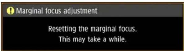
After the above window disappears, the values set in [Marginal focus] are cleared and the lens marginal focus is returned to the standard position. A reset can be applied regardless of whether [Marginal focus] is set to [On] or [Off].

Setting [Marginal focus] to [Off] will not reset the setting value for marginal focus. Select [Off] to preserve the setting value and prevent further adjustment.
Adjustment Using the Adjustable Feet
Adjustment in a range of ±1.8^ is possible using the adjustable feet.
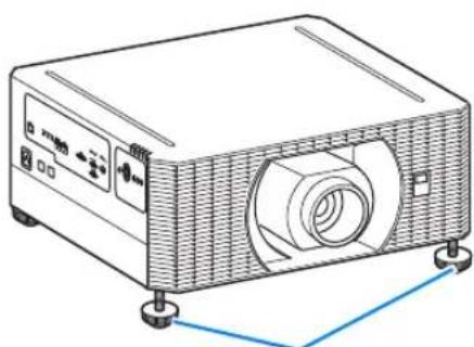
natural_image
Line drawing of a projector with control panel and base mount (no text or symbols)Adjustable feet
■ High Installation, Ceiling Mounting, and Rear Projection
Projector features enable projection from a shelf or other high surface. You can also mount the projector on the ceiling (ceiling mounting) with it turned upside down or place it behind the screen (rear projection) if you use a translucent screen. In [Image flip H/V] (P143) in the menu, choose a method of projection that corresponds to how the projector is installed.
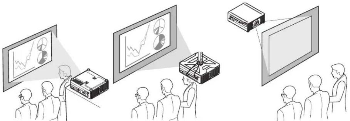
natural_image
Illustration of a presentation or presentation setup with multiple screens, a presenter, and audience members (no text or symbols present)Ceiling mounting Rear projection Installation on high surface
1 Press the MENU button on the remote control or projector, and then select [Install settings] > [Image flip H/V].
2Select the orientation of how the projector is installed.
| Option Function | |
| None Select for normal projection, without inversion. | |
| Ceiling mounted | Select when the projector is installed upside-down on the ceiling.The projected image is inverted in both vertical and horizontal directions. |
| Rear | Select this to project an image from behind the screen.The projected image is inverted in the horizontal direction. |
| Rear, Ceiling mounted | Select this to project an image from behind the screen with the projector hung from the ceiling.The projected image is inverted in the vertical direction. |
When setting the projector on a high surface for projection, be sure the surface is flat and stable. Failure to do so poses a risk of the projector falling and causing accidents or injury.
Ceiling mounting requires an optional ceiling attachment (part no.: RS-CL15) and ceiling-mount arm (part no.: RS-CL17). Depending on the installation environment, an extension pipe (part no.: RS-CL08 or RS-CL09) may also be required. Contact the Canon Customer Support Center for more detailed information.

- Make sure to use the optional ceiling attachment.
- You should never install the ceiling attachment by yourself.
Connection Procedure
Connecting Other Equipment

Caution
Before connecting the projector to other equipment, turn off both the projector and the other equipment.
■ HDMI Connections
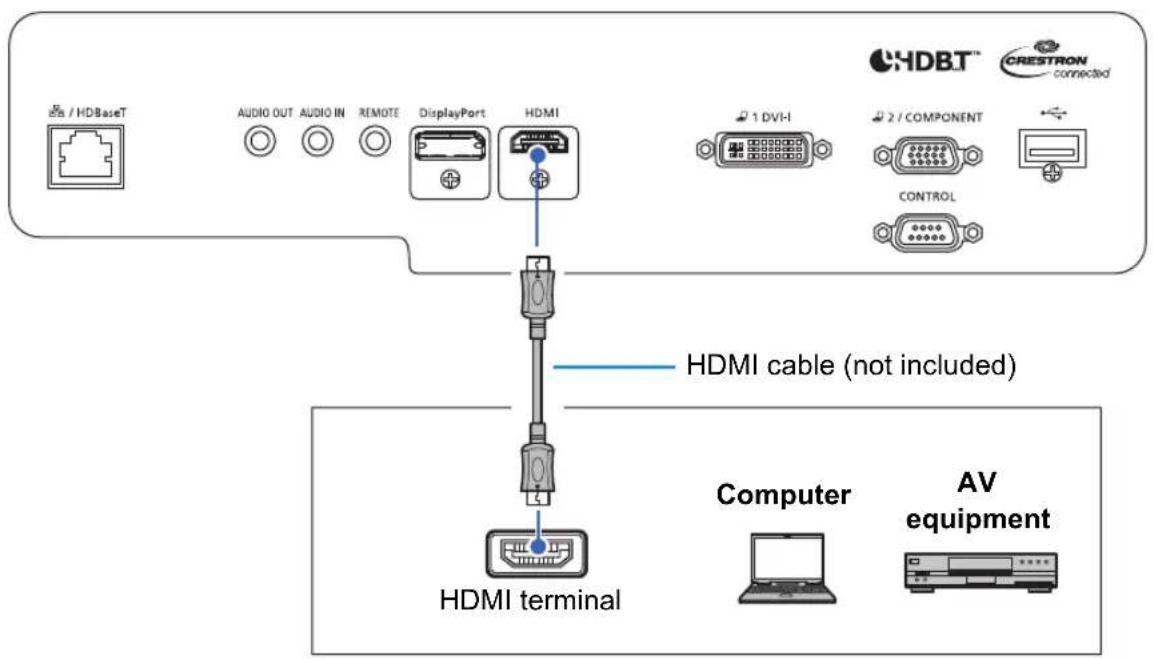
■ DVI-I Connections

flowchart
graph TD
    A["Computer"] --> B["DVI-D-sub 15 conversion cable"]
    A --> C["DVI-I cable (not included)"]
    B --> D["Monitor output terminal (Mini D-sub 15-pin)"]
    C --> E["Monitor output terminal (DVI terminal)"]
    F["ChDBT™"] --> G["AUDIO OUT"]
    F --> H["AUDIO IN"]
    F --> I["REMOTE"]
    F --> J["DisplayPort"]
    F --> K["HDMI"]
    G --> L["1 DVI-I"]
    H --> L
    I --> L
    J --> L
    K --> L
    L --> M["2 / COMPONENT"]
    L --> N["CONTROL"]
■ DisplayPort Connections
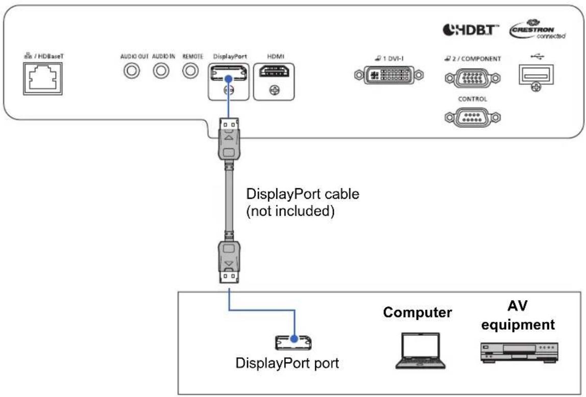
flowchart
graph TD
    A["DisplayPort cable (not included)"] --> B["DisplayPort port"]
    B --> C["Computer"]
    B --> D["AV equipment"]
■ Analog PC-2 / COMPONENT Connections
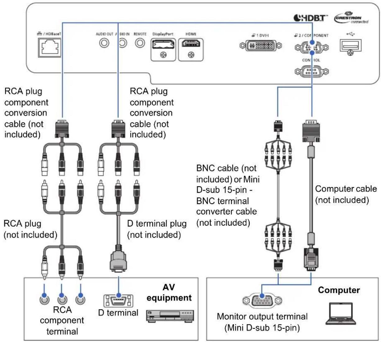
flowchart
graph TD
    A["HDBT™"] -->|RCA plug component conversion cable (not included)| B["RAA"]
    A -->|RCA plug component conversion cable (not included)| C["DRAA"]
    A -->|RCA plug component conversion cable (not included)| D["DRAA"]
    A -->|RCA plug component conversion cable (not included)| E["DRAA"]
    A -->|RCA plug component conversion cable (not included)| F["DRAA"]
    A -->|RCA plug component conversion cable (not included)| G["DRAA"]
    A -->|RCA plug component conversion cable (not included)| H["DRAA"]
    A -->|RCA plug component conversion cable (not included)| I["DRAA"]
    A -->|RCA plug component conversion cable (not included)| J["DRAA"]
    A -->|RCA plug component conversion cable (not included)| K["DRAA"]
    A -->|RCA plug component conversion cable (not included)| L["DRAA"]
    A -->|RCA plug component conversion cable (not included)| M["DRAA"]
    A -->|RCA plug component conversion cable (not included)| N["DRAA"]
    A -->|RCA plug component conversion cable (not included)| O["DRAA"]
    A -->|RCA plug component conversion cable (not included)| P["DRAA"]
    A -->|RCA plug component conversion cable (not included)| Q["DRAA"]
    A -->|RCA plug component conversion cable (not included)| R["DRAA"]
    A -->|RCA plug component conversion cable (not included)| S["DRAA"]
    A -->|RCA plug component conversion cable (not included)| T["DRAA"]
    A -->|RCA plug component conversion cable (not included)| U["DRAA"]
    A -->|RCA plug component conversion cable (not included)| V["DRAA"]
    A -->|RCA plug component conversion cable (not included)| W["DRAA"]
    A -->|RCA plug component conversion cable (not included)| X["DRAA"]
    A -->|RCA plug component conversion cable (not included)| Y["DRAA"]
    A -->|RCA plug component conversion cable (not included)| Z["DRAA"]
    A -->|RCA plug component conversion cable (not included)| AA["DRAA"]
    A -->|RCA plug component conversion cable (not included)| AB["DRAA"]
    A -->|RCA plug component conversion cable (not included)| AC["DRAA"]
    A -->|RCA plug component conversion cable (not included)| AD["DRAA"]
    A -->|RCA plug component conversion cable (not included)| AE["DRAA"]
    A -->|RCA plug component conversion cable (not included)| AF["DRAA"]
    A -->|RCA plug component conversion cable (not included)| AG["DRAA"]
    A -->|RCA plug component conversion cable (not included)| AH["DRAA"]
    A -->|RCA plug component conversion cable (not included)| AI["DRAA"]
    A -->|RCA plug component conversion cable (not included)| AJ["DRAA"]
    A -->|RCA plug component conversion cable (not included)| AK["DRAA"]
    A -->|RCA plug component conversion cable (not included)| AL["DRAA"]
    A -->|RCA plug component conversion cable (not included)| AM["DRAA"]
    A -->|RCA plug component conversion cable (not included)| AN["DRAA"]
    A -->|RCA plug component conversion cable (not included)| AO["DRAA"]
    A -->|RCA plug component conversion cable (not included)| AP["DRAA"]
    A -->|RCA plug component conversion cable (not included)| AQ["DRAA"]
    A -->|RCA plug component conversion cable (not included)| AR["DRAA"]
    A -->|RCA plug component conversion cable (not included)| AS["DRAA"]
    A -->|RCA plug component conversion cable (not included)| AT["DRAA"]
    A -->|RCA plug component conversion cable (not included)| AU["DRAA"]
    A -->|RCA plug component conversion cable (not included)| AV["DRAA"]
    A -->|RCA plug component conversion cable (not included)| AW["DRAA"]
    A -->|RCA plug component conversion cable (not included)| AX["DRAA"]
    A -->|RCA plug component conversion cable (not included)| AY["DRAA"]
    A -->|RCA plug component conversion cable (not included)| AZ["DRAA"]
    A -->|RCA plug component conversion cable (not included)| BA["DRAA"]
    A -->|RCA plug component conversion cable (not included)| BB["DRAA"]
    A -->|RCA plug component conversion cable (not included)| BC["DRAA"]
    A -->|RCA plug component conversion cable (not included)| BD["DRAA"]
    A -->|RCA plug component conversion cable (not included)| BE["DRAA"]
    A -->|RCA plug component conversion cable (not included)| BF["DRAA"]
    A -->|RCA plug component conversion cable (not included)| BG["DRAA"]
    A -->|RCA plug component conversion cable (not included)| BH["DRAA"]
    A -->|RCA plug component conversion cable (not included)| BI["DRAA"]
    A -->|RCA plug component conversion cable (not included)| BJ["DRAA"]
    A -->|RCA plug component conversion cable (not included)| BK["DRAA"]
    A -->|RCA plug component conversion cable (not included)| BL["DRAA"]
    A -->|RCA plug component conversion cable (not included)| BM["DRAA"]
    A -->|RCA plug component conversion cable (not included)| BN["DRAA"]
    A -->|RCA plug component conversion cable (not included)| BO["DRAA"]
    A -->|RCA plug component conversion cable (not included)| BP["DRAA"]
    A -->|RCA plug component conversion cable (not included)| BQ["DRAA"]
    A -->|RCA plug component conversion cable (not included)| BR["DRAA"]
    A -->|RCA plug component conversion cable (not included)| BS["DRAA"]
    A -->|RCA plug component conversion cable (not included)| BT["DRAA"]
    A -->|RCA plug component conversion cable (not included)| BU["DRAA"]
    A -->|RCA plug component conversion cable (not included)| BV["DRAA"]
    A -->|RCA plug component conversion cable (not included)| BW["DRAA"]
    A -->|RCA plug component conversion cable (not included)| BX["DRAA"]
    A -->|RCA plug component conversion cable (not included)| BYD["DRAA"]
    A -->|RCA plug component conversion cable (not included)| BZ["DRAA"]
    A -->|RCA plug component conversion cable (not included)| CA["AV equipment"]
    A -->|RCA plug component conversion cable (not included)| CB["AV equipment"]
    A -->|RCA plug component conversion cable (not included)| CC["AV equipment"]
    A -->|RCA plug component conversion cable (not included)| CD["AV equipment"]
    A -->|RCA plug component conversion cable (not included)| CE["AV equipment"]
    A -->|RCA plug component conversion cable (not included)| CF["AV equipment"]
    A -->|RCA plug component conversion cable (not included)| CG["AV equipment"]
    A -->|RCA plug component conversion cable (not included)| CH["AV equipment"]
    A -->|RCA plug component conversion cable (not included)| CI["AV equipment"]
    A -->|RCA plug component conversion cable (not included)| CJ["AV equipment"]
■ LAN / HDBaseT Connections
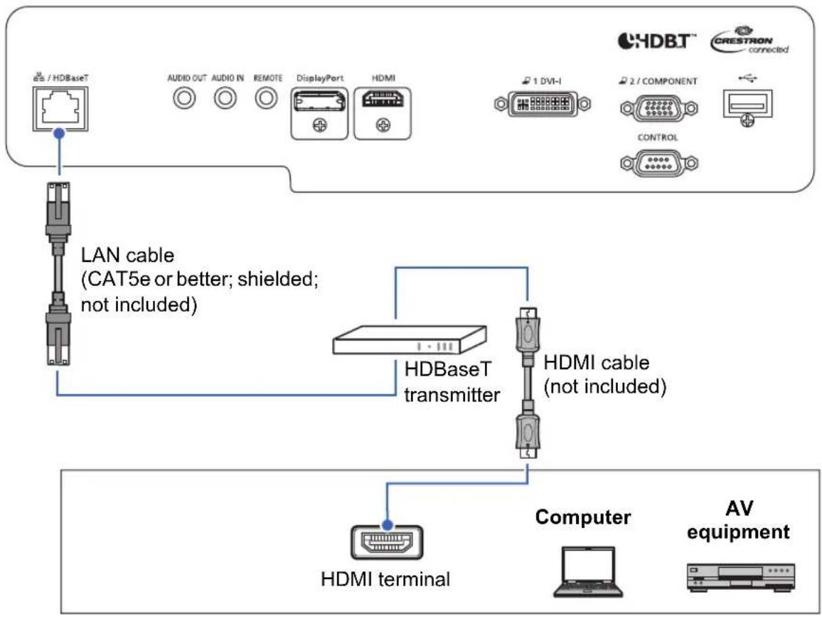
flowchart
graph TD
    A["GS / HDBaseT"] --> B["LAN cable (CAT5e or better; shielded; not included)"]
    B --> C["HDBaseT transmitter"]
    C --> D["Computer"]
    D --> E["AV equipment"]
    F["HDMI terminal"] --> C
    G["1 DVI-I"] --> H["HDMI"]
    I["2 / COMPONENT"] --> J["CONTROL"]
    K["AUDIO OUT"] --> L["LED"]
    M["AUDIO IN"] --> N["LED"]
    O["REMOTE"] --> P["LED"]
    Q["DisplayPort"] --> R["LED"]
    S["HDMI"] --> T["LED"]
■ Audio Input/Output Connections
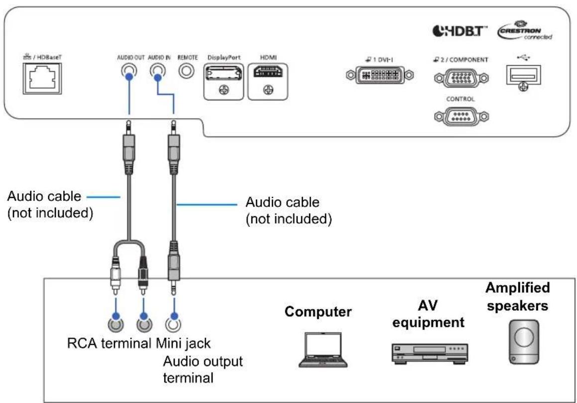
■ Plugging the Projector In
Connect the power cord to the projector and plug it in.
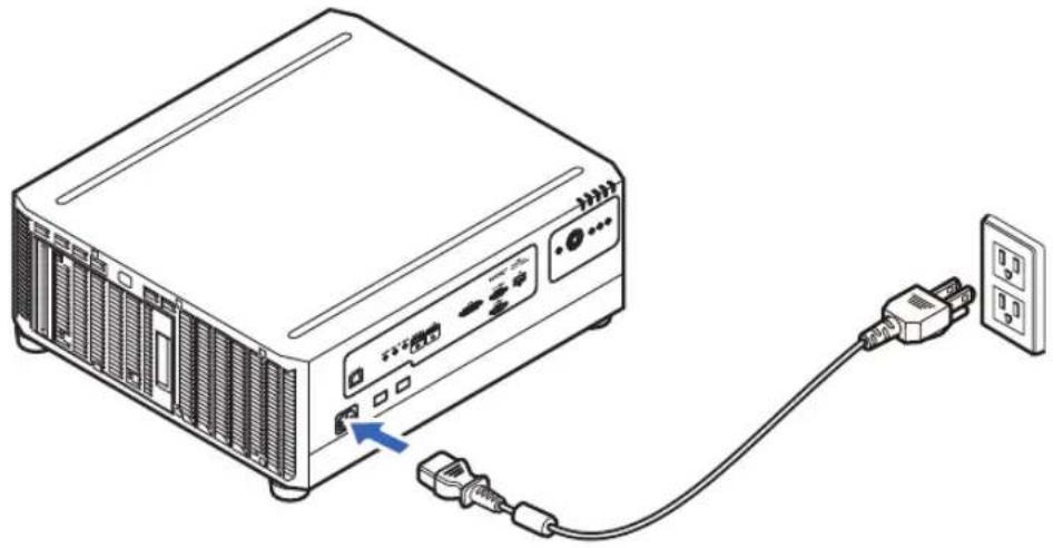
natural_image
Line drawing of a projector connected to a wall socket via cable (no text or symbols)
Insert the power plug and connector securely up to the base.

• After turning off the projector, wait at least 5 minutes before turning it on again. Turning the projector on immediately after turning it off may shorten the lamp life.
- Unplug the power cord if the projector will not be used for a long period of time.
- [Date and time settings] may be reset if the power cord is left unplugged for a long period of time (P166).
Connecting to a Network
■ Network Connection Overview
Connecting the projector to a network enables you to control the projector from a computer and receive notification of projector errors via email.
Depending on the method of network connection, preparation on the computer side may be necessary.
■ Connection Methods
The projector can be connected to a wired network with a LAN cable or to a wireless network via Wi-Fi.
Wired Networks
Use a LAN cable to connect the projector and computer to the network. Connect the LAN cable to the projector's LAN / HDBaseT port to enable communication.
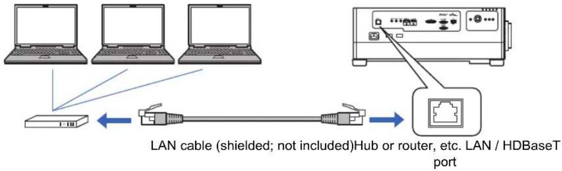
flowchart
graph TD
    A["Laptop"] --> B["Switch"]
    C["Laptop"] --> B
    D["Laptop"] --> B
    E["Router"] --> F["Port"]
    B <--> G["LAN cable (shielded; not included)Hub or router, etc. LAN / HDBaseT port"]
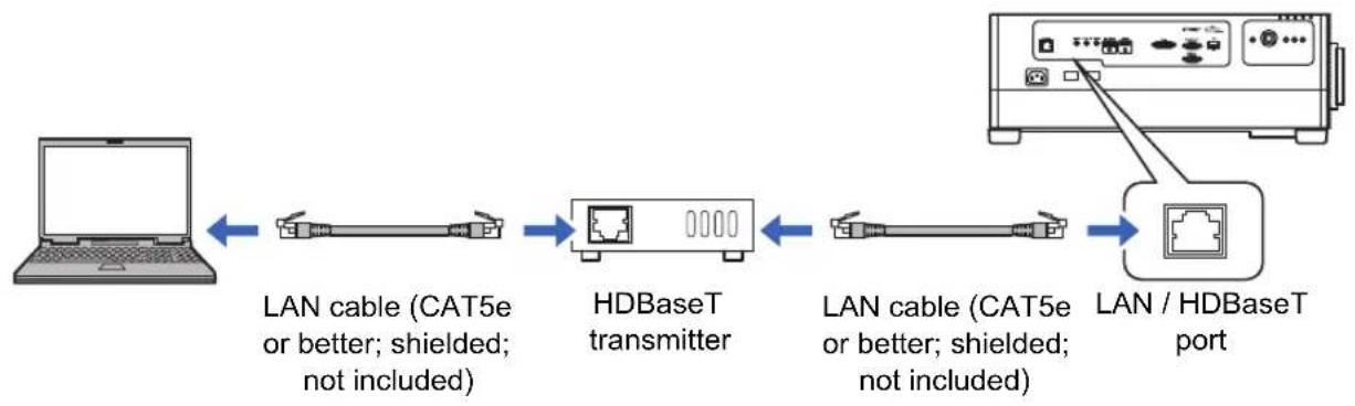
flowchart
graph LR
    A["Laptop"] -->|LAN cable (CAT5e or better; shielded; not included)| B["HWBaseT transmitter"]
    B -->|LAN cable (CAT5e or better; shielded; not included)| C["LAN / HDBaseT port"]
    C --> D["Computer with Ethernet port"]
Wireless Networks
- Projector Access Point (PJ AP) Mode
The projector can be used as an access point for direct communication with wireless LAN-compatible computers.
Up to five computers can be connected at once.
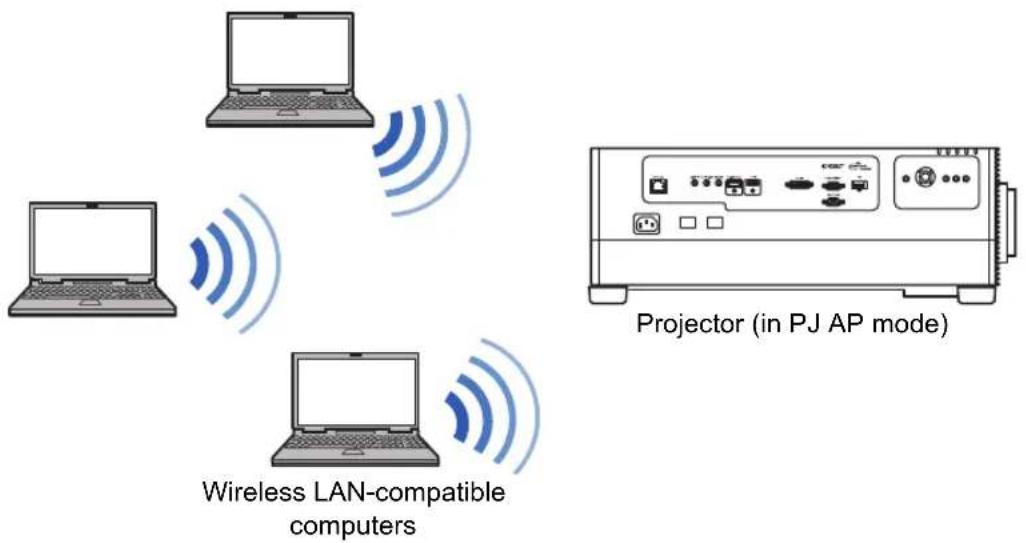
The following network features are available in PJ AP mode.
- Web features
• NMPJ features (networked screen projection) - User commands
- SNMP features
Other network features (PJLink, Mail, AMX Device Discovery and Crestron RoomView) are not available.
• Infrastructure Mode
The projector can also be used as a wireless LAN client for connections to a wireless LAN access point.
In this case, the projector is connected to computers via the wireless LAN access point.
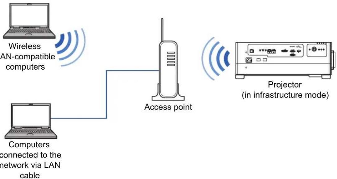
flowchart
graph LR
    A["Computers connected to the network via LAN cable"] --> B["Access point"]
    C["Wireless LAN-compatible computers"] --> B
    B --> D["Projector (in infrastructure mode)"]
Network connection
- The following network features are available in infrastructure mode.
- Web features
- Mail features
- NMPJ features (networked screen projection)
- User commands
- SNMP features
Other network features (PJLink, AMX Device Discovery and Crestron RoomView) are not available.
- The following restrictions apply in infrastructure mode.
- Access point SSIDs not in ASCII code (single-byte letters, numbers, or symbols) may cause character corruption in search result display.
- Connectivity cannot be assured if access point SSIDs include characters not in ASCII code (single-byte letters, numbers, or symbols).
When multiple access points have the same SSID, only search results for the access point with the strongest signal are shown.
- Remember to set your preferred network (wired or wireless) to [On] if [Network (wired/wireless)] on the projector is set to [Off/Off] and the network connection is disabled (P175). For wireless networks, choose the type of connection.
- The LAN / HDBaseT port provides a maximum transfer rate of 100 Mbps.
- Referring to “Checking Projector Information” (P188), confirm that the projector’s IP address is not the same as that of other computers on the network. To set a projector IP address, follow the instructions in “Basic Wired Network Settings [Wired]” (P195) or “Basic Wireless Network Settings [Wireless]” (P197) and use the web screen, or use the projector’s “Detailed settings (wired)” (P176) or “Detailed settings (wireless)” (P180).
- In a network environment where a DHCP server is operating, select [On] in [DHCP] on the projector to enable the DHCP function and connect it (P176, P182).

- Wired LAN features and infrastructure mode cannot be used at the same time.
- PJ AP and infrastructure modes cannot be used at the same time.
- Wired LAN and PJ AP mode cannot be used in the same subnetwork.
- When you connect the computer to the network for the first time, it is also necessary to perform settings on the computer. In this case, consult the network administrator regarding the necessary settings.
- Configuring the Computer’s Network Settings
Instructions for setting a computer's IP address (for wired connections or wireless connections) are as follows for each operating system.
Windows 10
1 Click the Start button (Windows logo) in the lower left of the screen.
2From [Windows system tools] on the Start menu that is displayed, click [Control Panel].
- On some versions of Windows 10, you must first click [All Apps] in order to display [Windows system tools].
3Click [View network status and tasks].
- In icon view:
Click [Network and Sharing Center].
4Click [Change adapter settings].
5For a wired connection, right-click [Ethernet], or for a wireless connection, right-click [Wi-Fi]. Next, click [Properties].
6In the [This connection uses the following items] list, select [Internet Protocol Version 4 (TCP/IPv4)] and click the [Properties] button. Make a note of the original network settings (IP address, subnet mask, default gateway, etc).
7 Select [Use the following IP address] and set the IP address and subnet mask.
The projector's own default IP address is "192.168.254.254" for wired connections and "192.168.253.254" for wireless connections. Specify a different IP address.
8 When the settings are completed, click the [OK] button, and then click the [Close] button in the [Ethernet Properties] window to close it.
Windows 8.1
1 Click the down arrow in the lower left of the start screen.
2Click [Control Panel].
- From the desktop screen:
Press Win+X.
In the shortcut menu displayed in the lower left, click [Control Panel].
3Click [View network status and tasks].
- In icon view:
Click [Network and Sharing Center].
4Click [Change adapter settings].
5For a wired connection, right-click [Ethernet], or for a wireless connection, right-click [Wi-Fi]. Next, click [Properties].
6Select [Internet Protocol Version 4 (TCP/IPv4)] and click the [Properties] button. Make a note of the original network settings (IP address, subnet mask, default gateway, etc).
7 Select [Use the following IP address] and set the IP address and subnet mask.
The projector's own default IP address is “192.168.254.254” for wired connections and “192.168.253.254” for wireless connections. Specify a different IP address.
8 When the settings are completed, click the [OK] button, and then click the [Close] button in the [Local Area Connection Properties] window to close it.
Windows 7
1 From the PC [Start] menu, select [Control Panel].
2Click [Network and Internet], and then click [View network status and tasks].
3From the menu on the left side of the window, click [Change adapter settings].
4 For a wired connection, right-click [Local Area Connection], or for a wireless connection, right-click [Wireless Network Connection]. Next, click [Properties].
5Select [Internet Protocol Version 4 (TCP/IPv4)] and click the [Properties] button. Make a note of the original network settings (IP address, subnet mask, default gateway, etc).
6Select [Use the following IP address] and set the IP address and subnet mask.
The projector's own default IP address is “192.168.254.254” for wired connections and “192.168.253.254” for wireless connections. Specify a different IP address.
7 When the settings are completed, click the [OK] button, and then click the [Close] button in the [Local Area Connection Properties] window to close it.
Mac OS X
1 Open the Apple Menu and select [System Preferences].
2In the System Preferences window, click [Network] to display the Network window.
3For a wired connection, select [Built-in Ethernet], or for a wireless connection, select [Wi-Fi]. Next, select [Detail].
4Click the [TCP/IP] tab. Make a note of the original network settings (IP address, subnet mask, router, DNS server, and so on).
5Create a new network environment and set the IP address and subnet mask.
The projector's own default IP address is "192.168.254.254" for wired connections and "192.168.253.254" for wireless connections. Specify a different IP address.
6Click [OK], then select [Apply] to close the network preference window.
Resetting the IP Address Setting of the Computer
Follow the same procedure as for changing the IP address and reset the values to the original values based on the notes taken before the change.
■ Setting Up the Network
Displaying the Network Configuration Screen
1 Turn on the computer and projector.

Network functions are not available until about 40 seconds after the projector is plugged in.
2Launch a web browser, enter "http://(projector IP address)" in the address bar, and press the Enter key.
The projector web screen appears.
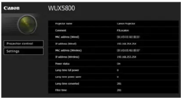
The following information is displayed.
| Projector control Displays the projector control screen. | |
| Settings Shows the settings screen. | |
| Projector name The name of the projector on the network | |
| Comment Relevant notes, such as where the projector is installed | |
| MAC address (Wired) MAC address of the wired LAN | |
| IP address (Wired) IP address of the wired LAN (IPv4) | |
| MAC address (Wireless) MAC address of the wireless LAN | |
| IP address (Wireless) IP address of the wireless LAN (IPv4) | |
| PowerStatus The power status of the projector | |
| Lamp time full power Lamp operating time in [Full power] lamp mode | |
| Lamp time power saver | Lamp operating time in [Power saver 1] lamp mode |
| Lamp time converted | Lamp operating time (converted value) |
| Filter time | Air filter operating time |
| Alert | Error message (if an error has occurred)Temperature abnormalityFaulty lampFaulty air filter unitFaulty cooling fanFaulty power supplyFaulty lens |

The factory default IP address is "192.168.254.254" for wired connections (IPv4) and "192.168.253.254" for wireless connections (IPv4). If DHCP settings are used, ask the network administrator for the projector IP address. It is possible to check the IP address from the projector menu (P176).
3Click [Settings] on the web screen.
The password input window appears.
4Enter the user name and password on the password input window, then click [OK].
The factory default user name is "root" and the password is "system". The settings screen is displayed. Complete the network settings on this screen.
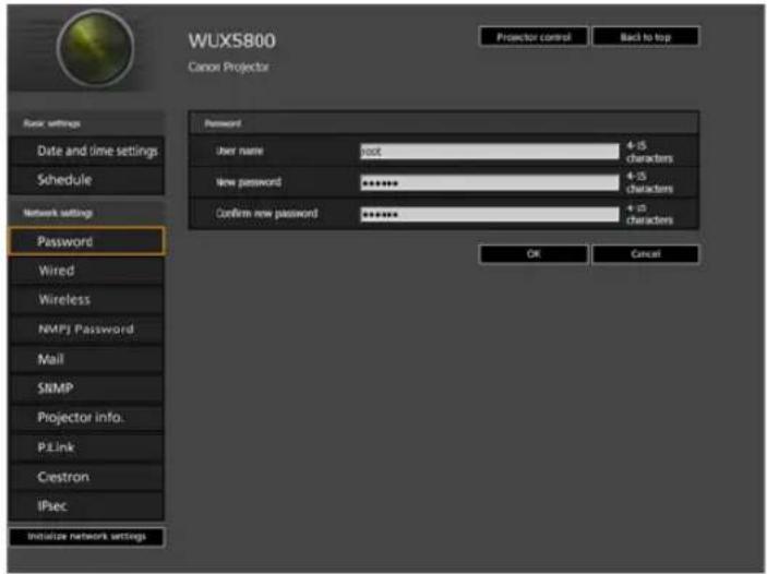
For details on the projector's web screen, see "Projector Web Screen Menu" (P189).
![CANON REALiS WUX6700 - 4Enter the user name and password on the password input window, then click [OK]. - 2](/content/2026/05/965391/images/b11ba1194abe1d7231c455195f99a249c5a47043311431ed43165ad7eb33b488.jpg)
To control the projector from the computer, click [Projector control] (P95).
Network Setting
1 Select a function to set up from the settings screen menu.

2Enter setting details in the fields shown (1), and then click [OK] (2).
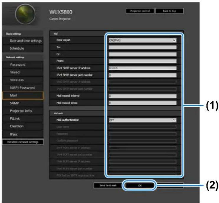
3A confirmation window appears. Check the contents and if they are correct, click [Apply].
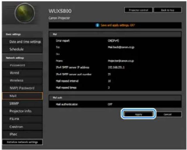
The settings are applied to the projector.
Selecting [Wired], [Wireless] or [Password] in the menu will cause this message to be displayed: "Save completed. Please change setting and reconnect."
If you select functions other than above, "Save completed" is displayed. Click [Back to top] to return to the top page of the web screen.
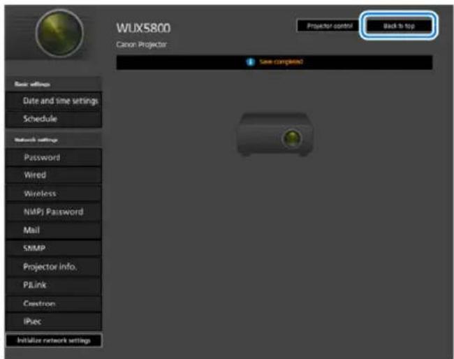
Setting Errors
When a setting-related error occurs, the error name is displayed on the screen, and a “! mark is displayed next to the input field which caused the error.
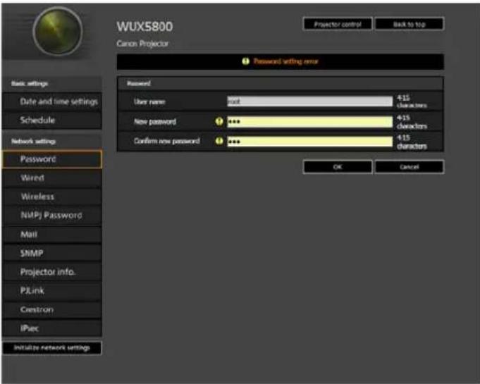
The error meanings are as shown below.
| Error Meaning | |
| Input error A setting outside the valid range | was set on the settings screen. |
| Password setting error The set password and confirmation password did not match. | |
| Invalid SMTP The SMTP server IP address has not been set. | |
| System failed to connect SMTP server. Failed to connect to the SMTP server attempting to send a test mail. | |
| System failed to connect POP3 server. Failed to connect to the POP3 server attempting to send a test mail. | |
| System doesn't support this auth type. An authentication type was set which is not supported by the server. | |
| System failed to authenticate. Authentication failed attempting to send a test mail. | |
| The system failed to send the test mail. Sending of test mail failed due to a connection failure with the SMTP server or an error which does not ordinarily occur. | |
| Wired network is down Wired networking is disabled. | |
| At the time of Monday, it is already set.* Failed to set the schedule, because operation is already scheduled for the specified time and day. | |
| Cannot make network settings because IPsec setting is ON. | It is not possible to make network settings because IPsec is set to [ON]. |
| Cannot make IPsec settings because DHCP setting is ON. | It is not possible to make IPsec settings because DHCP is set to [ON]. |
* Messages vary depending on the day.
Resetting Network Settings to the Default Settings
1 Perform steps 1 – 3 on “Setting Up the Network” (P87) to display the settings screen.
2Click [Initialize network settings].
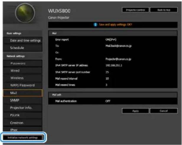
3A confirmation window appears. Click [OK].
■ Error Notification Mails
The messages shown in the following error list are sent when an error occurs in the projector.
Error list
| Errors related to temperature | Error name Temperature abnormality | |
| Text The | internal temperature of the projector is abnormally high, or else the ambient air temperature exceeds the threshold. If the problem is with the projector, verify that it is properly installed and is being used correctly, and let the inside of the projector cool down for a while with the power plug disconnected from the wall outlet before resuming projection. Remove any objects that are blocking the air intake or exhaust vent. If the air filter is clogged, try cleaning or replacing it. If the same warning is displayed again, the main unit may be faulty. Please contact your dealer. | |
| Errors related to the lamp | Error name Faulty lamp | |
| Text The | lamp has burnt out. Replace the lamp with a new one. If the same warning is displayed again, the lamp drive circuit or a related component may be faulty. Please contact your dealer. | |
| Errors related to the air filter | Error name Faulty air filter unit | |
| Text The | air filter is incorrectly installed, or a related component may be faulty. With the power off, re-install the air filter correctly, then turn the power back on. If the same warning is displayed again, please contact your dealer. | |
| Errors related to the fan | Error name Faulty cooling fan | |
| Text The | cooling fan or a related component may be faulty. With the power off, disconnect the power plug from the wall outlet, and then plug it in again and turn the power back on. If the same warning is displayed again, please contact your dealer. | |
| Errors related to the power | Error name Faulty power supply | |
| Text The | power supply voltage may be abnormal, or a related component may be faulty. With the power off, disconnect the power plug from the wall outlet, and then plug it in again and turn the power back on. If the same warning is displayed again, please contact your dealer. | |
| Errors related to the lens | Error name | Faulty lens |
| Text The | lens unit is incorrectly installed, or a related component may be faulty. With the power off, disconnect the power plug from the wall outlet, check whether the lens unit is installed properly, then turn the power back on. If the same warning is displayed again, please contact your dealer. | |
Controlling the Projector from a Computer
The projector can be controlled from a computer over a wired or wireless network connection.
1Turn on the computer and projector.
2 Launch a web browser, enter "http://(projector IP address)" in the address bar, and press the Enter key.
The projector web screen appears.

The factory default IP address is “192.168.254.254” for wired connections and “192.168.253.254” for wireless connections. If DHCP settings are used, ask the network administrator for the projector IP address. It is possible to check the IP address from the projector menu (P176).
3Click [Projector control] on the web screen.
The password input window appears.
4 Enter the user name and password on the password input window, then click [OK].
The factory default user name is "root" and the password is "system". The projector control screen appears.
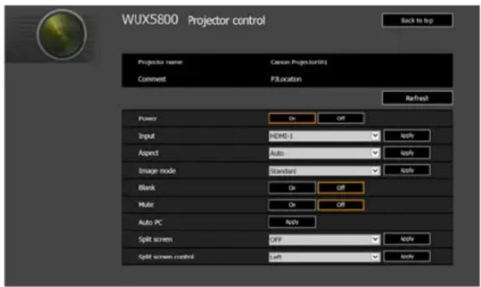
The projector can be controlled from this screen.
| Item Explanation | |
| Projector name | The name of the connected projector is displayed (P203). |
| Comment | Shows notes, such as where the projector is installed (P203). |
| Refresh Refreshes | the displayed contents with the most recent information. |
| Power Turns projector power on or off. | |
| Input Select an input signal and click [Apply] to change to that input signal (P45). | |
| Aspect | Select an aspect and click [Apply] to change to that aspect (P100). |
| Image mode Select an image mode and click [Apply] to change to that image mode (P47). | |
| Blank Switches the blank setting on or off (P50). | |
| Mute Switches the mute setting on or off (P52). | |
| Auto PC | Click [Apply] to perform Auto PC adjustment (P127). |
| Split screen Select the setting for split-screen mode and click [Apply] to switch split-screen display on or off. | |
| Split screen control | Select the control rights setting for split-screen mode and click [Apply] to switch the side currently under control. |
| Information The control results and control error information are displayed at the top of the screen. | |
5When the operations are finished, click [Back to top] to return the initial web screen.
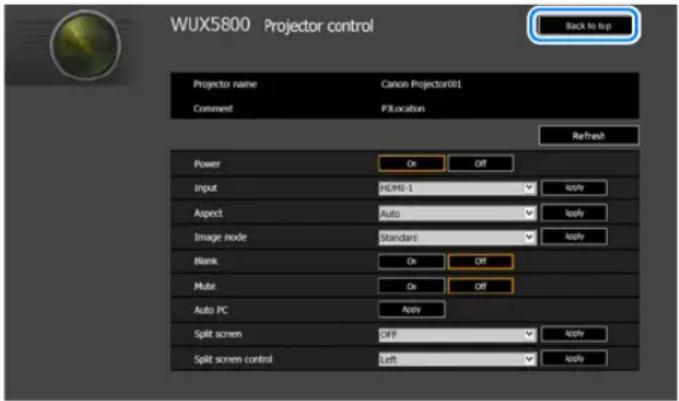
Adjusting the Image
Filling the Screen
Select an optimum screen aspect or an optimum projection aspect according to the aspect ratio of the screen, type of input image signal and so on for the projection to make best use of the screen size.
Specify the screen aspect and projection aspect, referring to the following table.
When projecting at the original aspect ratio on a 16:10 screen
| Original Aspect Ratio | Screen aspect setting (P99) | Aspect setting (P100) | Screen image |
| (16:10)1920 x 12001440 x 9001280 x 800 | [16:10] | [16:10][Auto] | 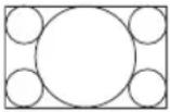 |
| (16:9)1920 x 10801280 x 720 | [16:9][Auto] | 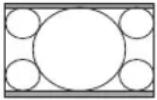 | |
| (4:3)1600 x 12001400 x 1050640 x 480 | [4:3][Auto] | 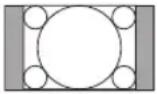 |
When projecting at the original aspect ratio on a 16:9 screen
| Original Aspect Ratio | Screen aspect setting (P99) | Aspect setting (P100) | Screen image |
| (16:10)1920 x 12001440 x 9001280 x 800 | [16:9][16:9 D. image shift] | [Auto] | 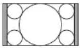 |
| (16:9)1920 x 10801280 x 720 | [16:9][Auto] | 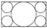 | |
| (4:3)1600 x 12001400 x 1050640 x 480 | [4:3][Auto] | 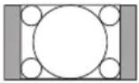 |
When projecting at the original aspect ratio on a 4:3 screen
| Original Aspect Ratio | Screen aspect setting (P99) | Aspect setting (P100) | Screen image |
| (16:10)1920 x 12001440 x 9001280 x 800 | [4:3][4:3 D. image shift] | [16:10][Auto] | 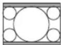 |
| (16:9)1920 x 10801280 x 720 | [16:9][Auto] | 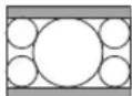 | |
| (4:3)1600 x 12001400 x 1050640 x 480 | [4:3][Auto] | 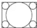 |
When projecting to fill a 16:10 screen
| Original Aspect Ratio | Screen aspect setting (P99) | Aspect setting (P100) | Screen image |
| (16:10)1920 x 12001440 x 9001280 x 800 | [16:10] | [16:10][Auto] | 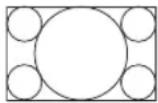 |
| (16:9)1920 x 10801280 x 720 | [16:10] | 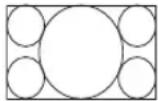 | |
| (4:3)1600 x 12001400 x 1050640 x 480 | [16:10] | 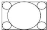 |
When projecting to fill a 16:9 screen
| Original Aspect Ratio | Screen aspect setting (P99) | Aspect setting (P100) | Screen image |
| (16:10)1920 x 12001440 x 9001280 x 800 | [16:9][16:9 D. image shift] | [16:9] | 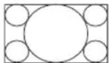 |
| (16:9)1920 x 10801280 x 720 | [16:9][Auto] | 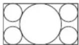 | |
| (4:3)1600 x 12001400 x 1050640 x 480 | [16:9] | 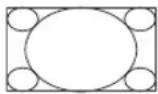 |
When projecting to fill a 4:3 screen
| Original Aspect Ratio | Screen aspect setting | Aspect setting (P100) | Screen image |
| (16:10)1920 x 12001440 x 9001280 x 800 | [4:3][4:3 D. image shift] | [4:3] | 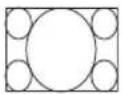 |
| (16:9)1920 x 10801280 x 720 | [4:3] | 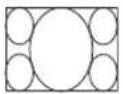 | |
| (4:3)1600 x 12001400 x 1050640 x 480 | [4:3][Auto] | 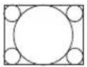 |
■ Selecting Screen Aspect
Select the correct aspect ratio for the screen which is used.
From the menu window, select [Install settings] > [Screen aspect].
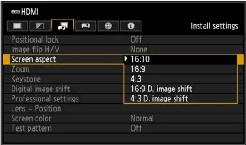
| Option Function | |
| 16:10* | Select this when you use a screen with an aspect ratio of 16:10. Also select this screen aspect when projecting on a wall. |
| 16:9* Select this when you | use a screen with an aspect ratio of 16:9. |
| 4:3* Select this when you | use a screen with an aspect ratio of 4:3. |
| 16:9 D. image shift | Select this when you use a screen with an aspect ratio of 16:9. Although keystone correction is not available in this mode, the image can be shifted up or down when projecting straight ahead. |
| 4:3 D. image shift | Select this when you use a screen with an aspect ratio of 4:3. Although keystone correction is not available in this mode, the image can be shifted left or right when projecting straight ahead. |
* Keystone distortion can be corrected in this mode.

- Changing the screen aspect will reset any keystone or digital image shift setting.
- [Auto] may be automatically selected in [Aspect] depending on the screen aspect setting.
■ Selecting an Aspect Ratio
Select an aspect ratio type based on the input signal type, aspect ratio of the screen and resolution.
Press the ASPECT button on the remote control to change the aspect ratio type.*
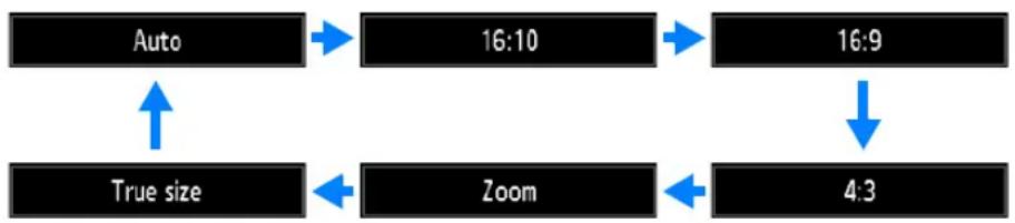
flowchart
graph TD
    A["Auto"] --> B["16:10"]
    B --> C["16:9"]
    C --> D["4:3"]
    D --> E["Zoom"]
    E --> F["True size"]
    F --> A
| Option Function | |
| Auto | An image is projected at the aspect ratio of the input signal. Select this mode for normal image projection. |
| 16:10* | The image is projected using an input signal aspect ratio of 16:10. Select this if an image of 16:10 aspect ratio cannot be correctly projected in [Auto] mode. |
| 16:9 | The image is projected using an input signal aspect ratio of 16:9. Select this if an image of 16:9 aspect ratio cannot be correctly projected in [Auto] mode. |
| 4:3 | The image is projected using an input signal aspect ratio of 4:3. Select this if an image of 4:3 aspect ratio cannot be correctly projected in [Auto] mode. |
| Zoom* | This cuts the upper/lower or left/right part of the screen according to the screen aspect and zooms in the center of the image. Select this if a letter box is displayed (black lines at the top/bottom of the screen) when watching video. |
| True size* | The image is projected with the original resolution of the input signal. Screens of computers with a lower display resolution than the projector are displayed smaller but clearer than in other aspect ratios. |
* There may be some cases when this cannot be selected, depending on the input signal and/or resolution. Menus that are not available are grayed out or hidden.

- For LAN and USB input, [Auto] is selected automatically.
- Different contents are displayed for different screen aspects or input signal types.
- The aspect ratio type can also be switched from the menu accessed from [Input settings] > [Aspect] (P127).
■ Relationship between Aspect and Screen Aspect

- If a computer image with an aspect ratio of 16:9 is not projected correctly when the setting is [Auto], select [16:9] as the screen aspect.
- For a 16:9 image with black borders at the top and bottom, such as a terrestrial broadcast movie, you can project the 16:9 image area so that it is projected on the entire screen by selecting [Zoom] in [Aspect].
There may be some cases that [Zoom] cannot be selected depending on the input signal and/or resolution. - For keystone correction, select an option other than [4:3 D. image shift] or [16:9 D. image shift] for Screen aspect.
Adjusting Keystone Distortion
Two types of correction are available: horizontal/vertical correction and corner correction.
Use horizontal/vertical keystone correction to adjust image width or height distortion separately, and use corner correction to adjust the position of each corner of the image.
Keystone correction is also possible by pressing the KEYSTONE button on the remote control or projector.
■ Horizontal/Vertical Keystone Correction
1 Select [Install settings] > [Keystone] > [Horizontal-vertical keystone].
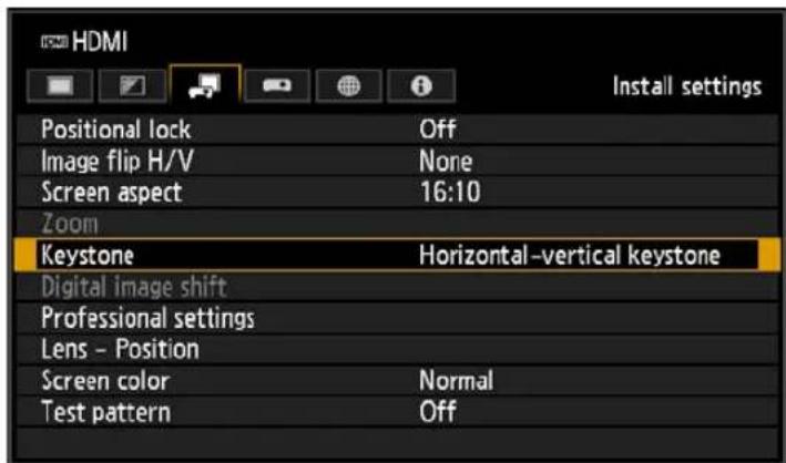
2 Press the KEYSTONE button on the remote control or projector to display the [Horizontal-vertical keystone adjustment] window.
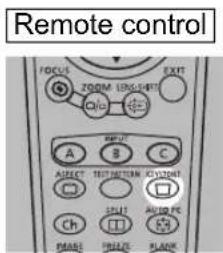
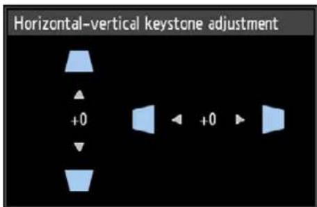
3Press the pointer buttons to adjust the dimensions, and then press the OK button.
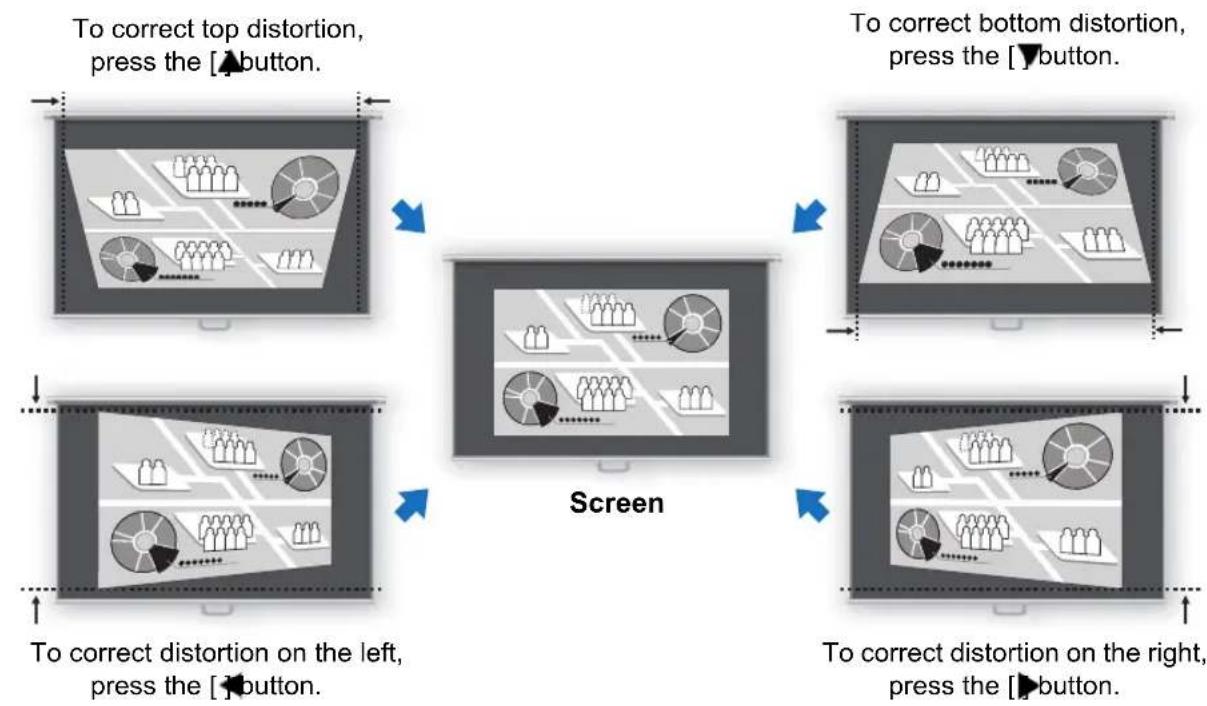
flowchart
graph TD
    A["To correct top distortion, press the [▲button."]] --> B["Screen"]
    C["To correct bottom distortion, press the [▼button."]] --> B
    D["To correct distortion on the left, press the [◀button."]] --> B
    E["To correct distortion on the right, press the [▶button."]] --> B

- [Zoom] (P144) in the [Install settings] menu is not available during horizontal/vertical keystone correction.
- The available horizontal-vertical keystone range may vary depending on the lens, zoom position, and shift position.
■ Corner Adjustment
1 Select [Install settings] > [Keystone] > [Corner adjustment].
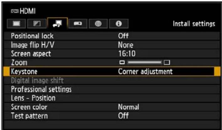
Adjusting the Image
2Press the KEYSTONE button on the remote control or projector to display the [Corner adjustment] window.
Remote control
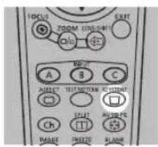
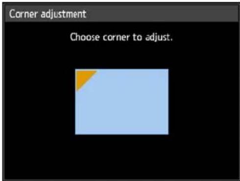
3Press the pointer button of the corner for correction, and then press the OK button.
Remote control
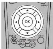
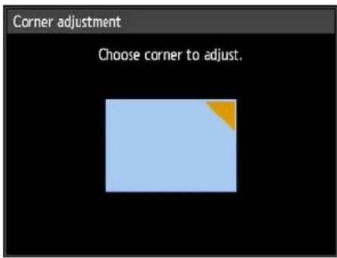
4Press the pointer buttons to adjust the corner, and then press the OK button.
Remote control
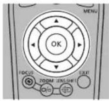
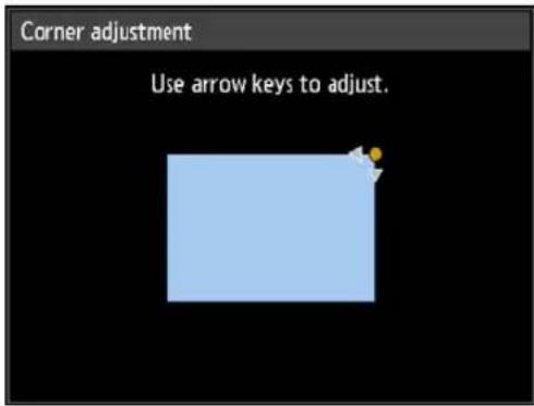

Corner adjustment settings will be cleared if you subsequently use [Zoom] (P144) in the [Install settings] menu.
Adjusting the Image
Resetting the Keystone Adjustment
First, press the KEYSTONE button on the remote control or projector twice to display the [Keystone reset] window.
Next, select [OK] with the [◀] button, and then press the OK button.
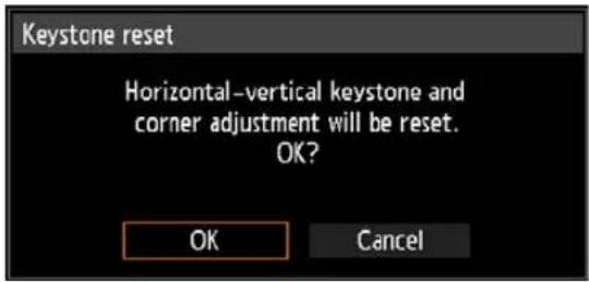
Adjustment Using a Test Pattern
Resolution and colors can be adjusted during installation by using test patterns. To access the test pattern menu, select [Test pattern] > [On] (P152) in the [Install settings] menu or press the TEST PATTERN button on the remote control. While the test pattern is displayed, you can use the [▲/ [ ]▼buttons to switch patterns. Also, if there is an option pattern available, you can use the [◀/ [ ]▶ buttons to switch pattern. A dialog box is shown during test pattern display that identifies the current test pattern and provides operating instructions. Watch the test pattern projected as you adjust the image. The following test patterns can be displayed.
Use [▲/ [ ]▼o switch patterns
Use [◀/ [ ]▶to switch option patterns
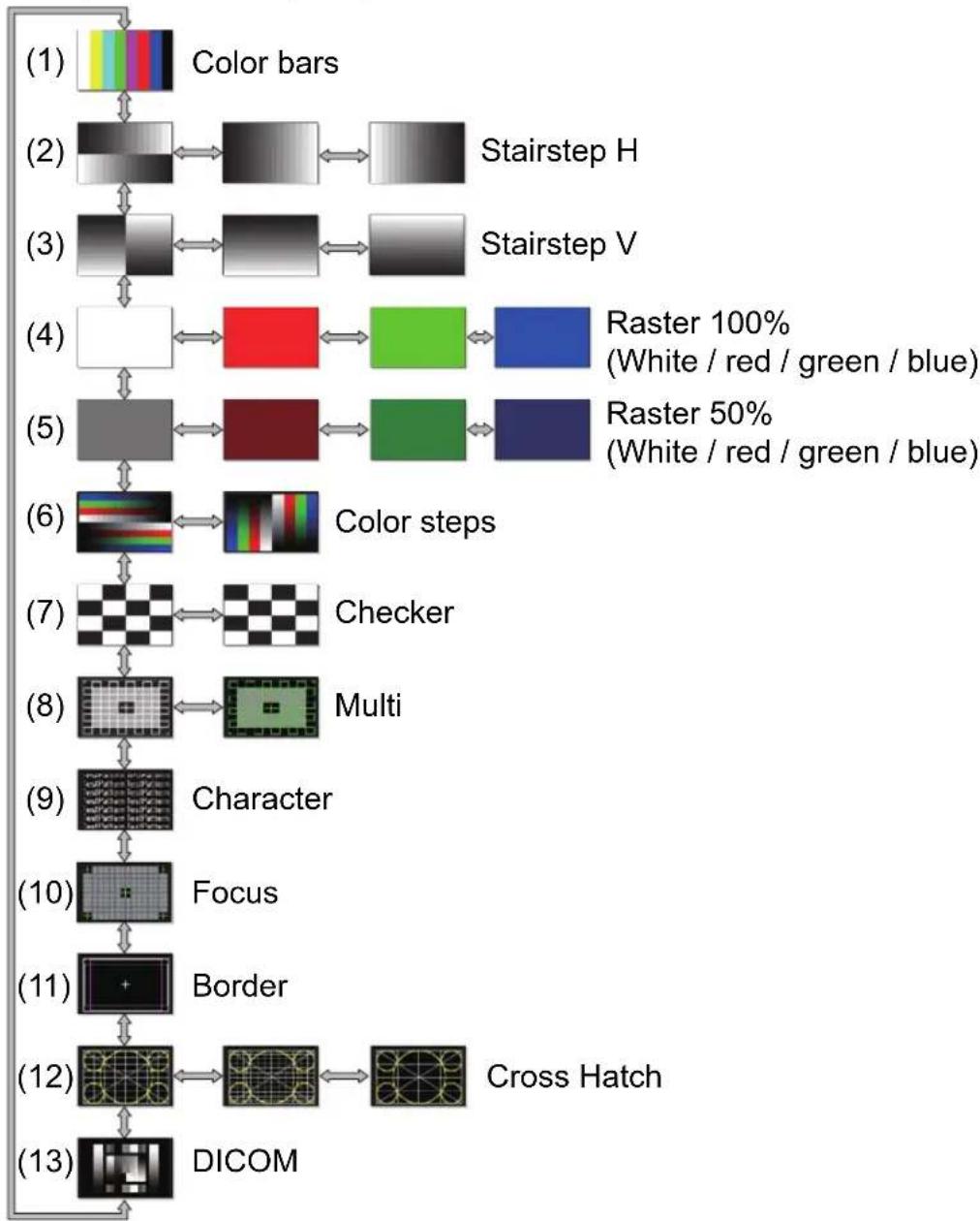
flowchart
graph TD
    A["(1) Color bars"] --> B["(2) Stairstep H"]
    B --> C["(3) Stairstep V"]
    C --> D["(4) Raster 100% (White / red / green / blue)"]
    D --> E["(5) Raster 50% (White / red / green / blue)"]
    E --> F["(6) Color steps"]
    F --> G["(7) Checker"]
    G --> H["(8) Multi"]
    H --> I["(9) Character"]
    I --> J["(10) Focus"]
    J --> K["(11) Border"]
    K --> L["(12) Cross Hatch"]
    L --> M["(13) DICOM"]
Special Arrangements
Projecting from Multiple Projectors at Once (Edge Blending)
Overlapping edges of images from multiple projectors used together can be blended to make the overall image more seamless. This feature is called edge blending.
Follow these steps for basic edge blending with two projectors side by side.

Keep in mind when projecting from multiple projectors that each unit may have a different color balance. Thus, even with the same model, differences in color may be noticeable.
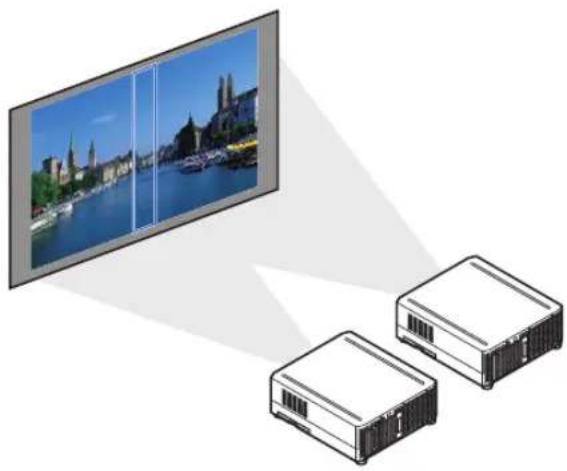
natural_image
Illustration showing a TV screen displaying a scenic cityscape with boats, connected to two rectangular storage units (no text or symbols present)1 Select [Install settings] > [Professional settings] > [Edge blending] > [Adjust].
| Edge blending | ||
| Side | Width | Start position |
| Left | 0 | 0 |
| Right | 0 | 0 |
| Top | 0 | 0 |
| Bottom | 0 | 0 |
| Color blending adjustment | Off | |
| Black level adjustment | Off | |
| Marker | Off | |
| Reset | ||
| Corner adjustment | ||
| Return | ||
2Set [Marker] to [On].
Marker lines are projected on the images. The red marker indicates the start position for adjustment, and the green marker, the end position.
Initially, only the red marker is visible when you prepare for edge blending, because it is projected over the green marker.
![CANON REALiS WUX6700 - 2Set [Marker] to [On]. - 1](/content/2026/05/965391/images/40d3adfb046e1820227d0cd5e7d0f71ec1a6ce87d0e71eed5a13f897cbf91a59.jpg)
natural_image
Diagram showing two rectangular panels with internal structures and a central vertical bar, no text or symbols present.3In [Side], select [Start position] and use the [ ] ▲[ ] buttons to move the start marker to the outer edge of the overlapping area.
Do this for each edge; on the top, bottom, left, and right.
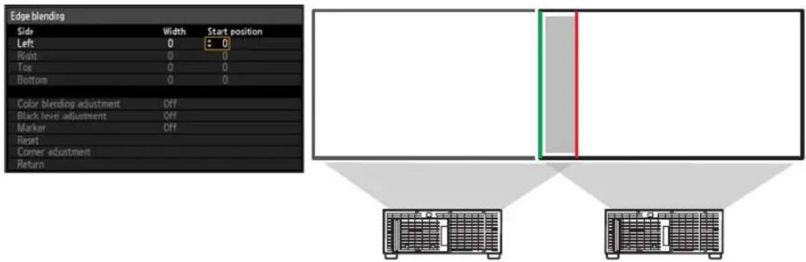
4Select [Width] and use the [ ] ▲[ ] buttons to move the end marker to the inner edge of the overlapping area.
Do this for each edge; on the top, bottom, left, and right.
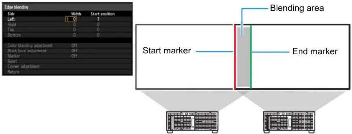
Special Arrangements
The area between the starting and ending markers is called the blending area. Shading is applied to this area, and the brightness is adjusted to match portions that overlap with other areas. After you complete settings for one image, do the same thing for the other one to specify the blending area. Adjust the settings to make the blending area for each image the same.
5Set [Marker] to [Off].
■ Adjusting the Overlapping Area
Adjust the overlapping area to create a smoother transition between projected images.
Matching Colors in the Overlapping Area
In overlapping projection, portions of images in the overlapping area that pick up other colors or are miscolored may be more noticeable. You can make this overlapping area appear less distracting by performing [Color blending adjustment].
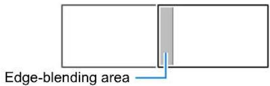
1 Select [Install settings] > [Professional settings] > [Edge blending] > [Adjust] > [Color blending adjustment] > [Adjust].
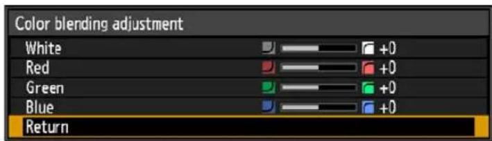
2First adjust red, green, and blue together by changing the [White] value, and then adjust [Red], [Green], and [Blue] values individually.
3 Repeat this adjustment on all projectors.
Matching Black in the Overlapping Area
In overlapping projection, dark colors are projected with less intensity than other colors in the overlapping area. You can make this overlapping area less distracting by adjusting the black level of non-overlapping image areas.
Here, the non-overlapping image area (from the end marker toward the center of the image) is called area "D."
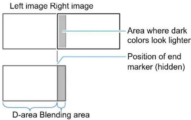
Normally, three areas are identified in the context of end markers: A, B, and C. In the following instructions, only area D is adjusted, and the widths of A, B, and C are left at the default value of 0.

To prepare for adjustment, select [System settings] > [User screen settings] > [No signal screen] > [Black], start projection with no input signal, and turn off the room lights, so that you can check dark image areas.
1 Select [Install settings] > [Professional settings] > [Edge blending] > [Adjust] > [Black level adjustment] > [Adjust].
2Select [Adjustment type] > [Black level].
3After selecting [D-area base], as you watch the image, adjust the values so that the brightness and colors of the blending area and area D match.
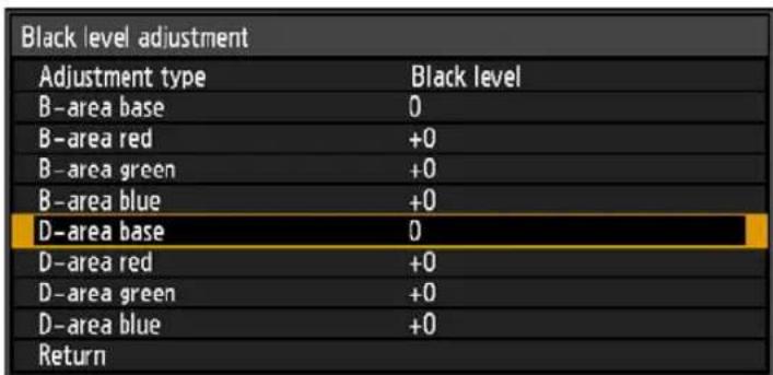
4 Repeat this adjustment on all projectors.
■ Making Overlapping Edges Less Noticeable
The black level along the right edge of area D (along the blending area) may be more noticeable than that of surrounding areas. By adjusting the black level of area B, you can make the transition smoother. To compensate, adjust each area as follows.
When the projected image has multiple blending areas (on the top, bottom, and each side), the width of areas A, B, and C must be adjusted to suit these blending areas.
In this example, instructions are given for adjusting area B.
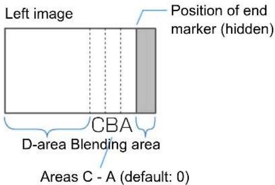
Area A: Black level cannot be adjusted.
Area B: Adjust to a black level different from that of area D.
Area C: Adjust to provide a smooth transition relative to the black levels of areas B and D.
1 Select [Install settings] > [Professional settings] > [Edge blending] > [Adjust] > [Black level adjustment] > [Adjust].
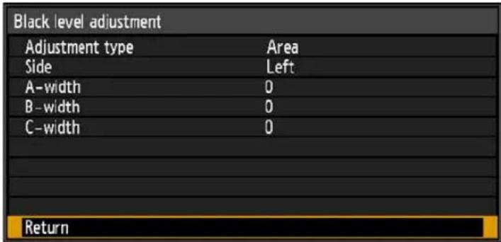
2Select [Adjustment type] > [Area] > [Side] > [Right].
3Select [B-width], and then adjust the width of area B to roughly match the area where the black level is noticeable.
4Select [Adjustment type] > [Black level]. Adjust [B-area base] as you watch the image.
5As you watch the image, adjust the width of areas A, B, and C.
6Readjust the black level of area B, as needed.
![CANON REALiS WUX6700 - Select [Install settings] > [Professional settings] > [Edge blending] > [Adjust] > [Black level adjustment] > [Adjust]. - 2](/content/2026/05/965391/images/3340f2813e292e40160a68c912f4e5cbc6306f51fc574214668e1c636775e74c.jpg)
- Results of adjusting the black level of area B are applied to all sides.
- If you perform adjustments using [Color blending adjustment] or other menus, that may not eliminate the distracting colors and differences in brightness in areas where the images overlap.
- Blending can be fine-tuned by adjusting [Adjustment type] > [Black level] > [Red], [Green], and [Blue].
■ Corner Adjustment
Projected images from multiple projectors used in overlapping projection must be precisely repositioned. Positions of each corner in the blending area can be aligned with the blending area of the reference projector.
1 On the reference projector, configure keystone (P145) and edge-blending (P148) settings, and then set the edge-blending markers to [On] (P106).
2 Select [Install settings] > [Professional settings] > [Edge blending] > [Adjust] > [Corner adjustment].
3Select a point to adjust, and move it so that the image as a whole looks symmetrical.
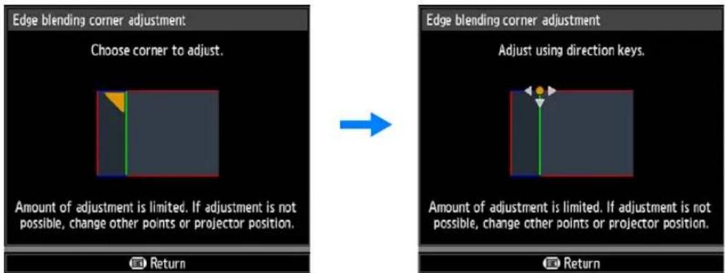
4As you watch the projected images, fine-tune markers of the projector you are adjusting so that they overlap the reference projector markers as much as possible.
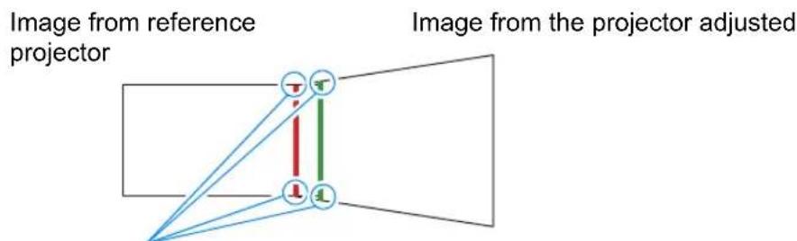
Adjust positions of each of the four corners in the overlapping area. Correcting the position of one point will also move the point on the opposite side of the overlapping area, so that the screen as a whole is corrected.
5 Set the reference projector's edge-blending markers to [Off] (P106).
![CANON REALiS WUX6700 - Set the reference projector's edge-blending markers to [Off] (P106). - 1](/content/2026/05/965391/images/36f5d741915159b874ef521429e94019ef5eb7b0c5cec2e4038003fd34ce908e.jpg)
- First, complete [Side] adjustment (P106).
- Sides set to an edge-blending width of 12 or more can be adjusted when [Keystone] is set to [Corner adjustment] and the aspect ratio is [16:10].
• To reset adjustment, use [Keystone] (P145). - A small edge-blending width may limit the amount of adjustment available.
Using PC-Free Multi Projection
A JPEG image on a USB flash drive can be divided among up to nine projectors and combined into a single, large image.
When projectors are connected via a wired LAN, the projector that produces the image in the upper left is called the Primary projector and the other eight, Secondary projectors. The image as a whole is controlled by the Primary projector.
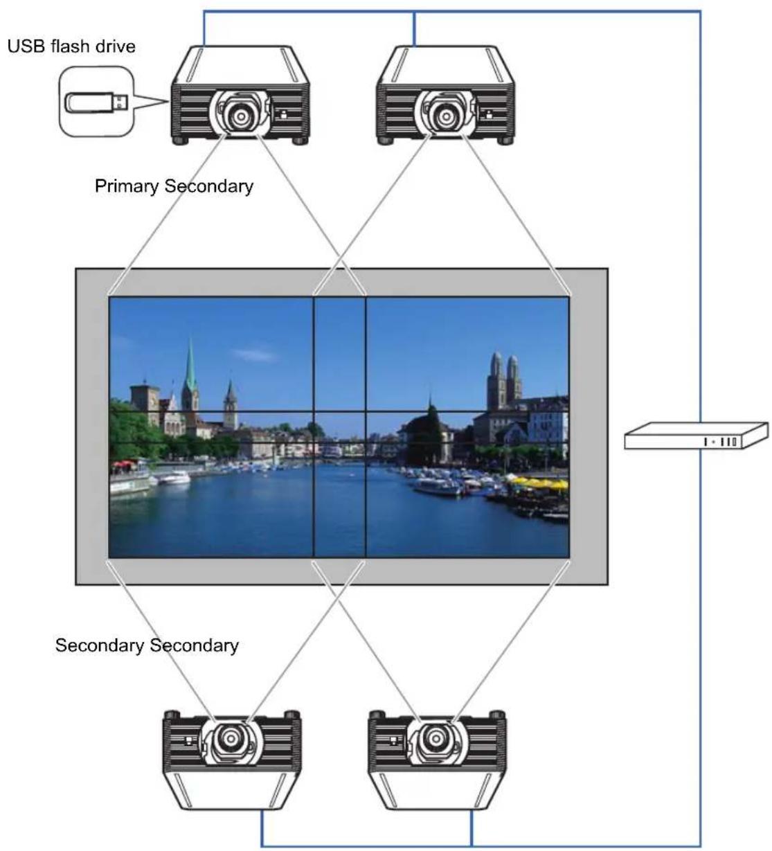
flowchart
graph TD
    A["USB flash drive"] --> B["Primary Secondary Camera"]
    C["Primary Secondary Camera"] --> B
    D["Secondary Secondary Camera"] --> B
    E["Secondary Secondary Camera"] --> B
    B --> F["1 - 110"]

PC-free multi projection is not available over a wireless LAN.
Special Arrangements
This feature is available with the following number of projectors and layout patterns. The projector you assign as the Primary projector, identified in the layout pattern as [1] , always projects the upper-left image.
| No. of Projectors | Layout Pattern (Columns x Rows) | ||
| 2 | [2 x 1] | ||
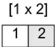 |  | ||
| 3 | [1 x 3] | ||
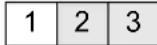 | |||
| 4 | [1 x 4] | [2 x 2] | |
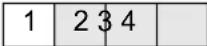 | 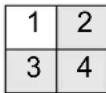 | ||
| 5 | [1 x 5] | ||
 | |||
| 6 | [1 x 6] | [2 x 3] | [3 x 2] |
 | 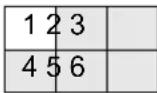 | 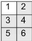 | |
| 7 | [1 x 7] | ||
 | |||
| 8 | [1 x 8] | [2 x 4] | 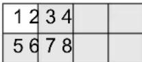 |
 | |||
| 9 | [1 x 9] | [3 x 3] | 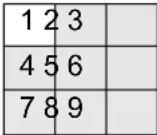 |
 | |||
Set up the projectors as follows.
1 On each projector, configure installation and image adjustment settings such as edge blending (P106) and keystone correction (P101) to blend overlapping areas.
2Connect the projectors with LAN cables and set [Network (wired/wireless)] to [On/Off] or [On/On (Pj AP)] (P175).
3Configure some projectors as Secondaries.
Select [Input settings] > [PC-free multi projection] > [Mode setting] > [Secondary].
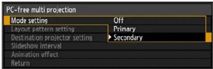

Complete this setting on each Secondary projector.
4Configure one projector as the Primary projector.
(1) Select [Input settings] > [PC-free multi projection] > [Mode setting] > [Primary].
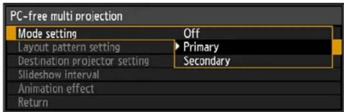
(2) Configure the following settings in [PC-free multi projection].
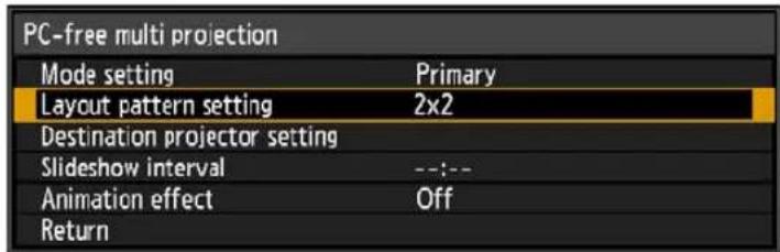
- [Layout pattern setting]
Specify the total number of projectors and the layout pattern (P113).
• [Destination projector setting]
Specify Secondary projector IP addresses. - [Slideshow interval]
Specify the slideshow interval (5 seconds to 10 minutes).
• [Animation effect]
Specify the transition to use for slideshows.
5On the Primary projector, select [Input settings] > [PC-free multi projection] > [Destination projector setting] > [Confirm] and check the number assigned to each projector.
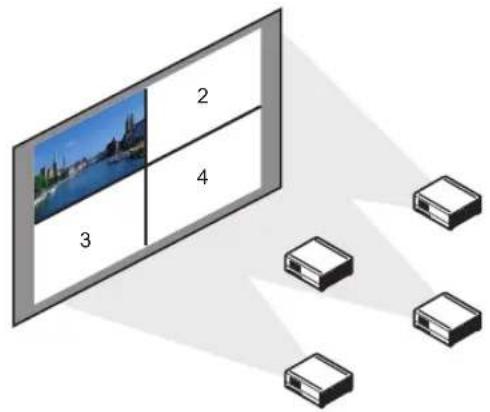
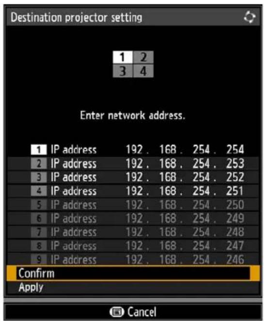

- If the projector is turned off and then on again during projection, the slideshow automatically resumes from the first image in the folder last used for projection.
- If the image does not switch to the image for the corresponding number, adjust the IP address setting.
Menu Guide
Using Menus
Use the menus to set the operation of the projector in detail.
1 Press the MENU button to display the menu window.
Remote control
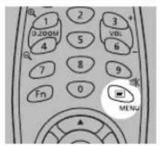
Projector
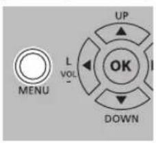
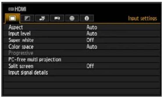
2Press the [ ] /[ ] buttons to select a tab.
Remote control
Projector
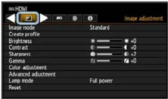
- If the tab position is not highlighted in orange, press the [ ]N [ ] Buttons to move the current selection to the top.
3Press the [ ] ▲[ ] buttons to select an item.
Remote control
Projector
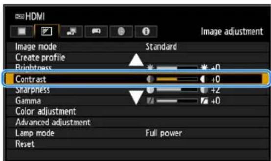
4Select contents.
How to select the contents varies depending on the item.
Selecting from a list Example: Aspect (P127)
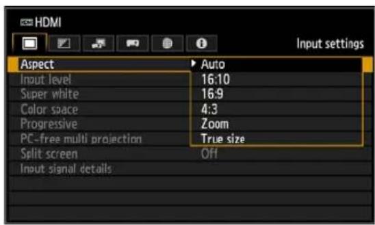
- Select [Aspect].
- Press the OK button or [ ] button to display a list of the contents.
- Use the [ ] buttons to select the desired contents.
- When you have found the contents you desired, press the OK button or [▶].
Adjusting with the [ ]/ [ ]buttons
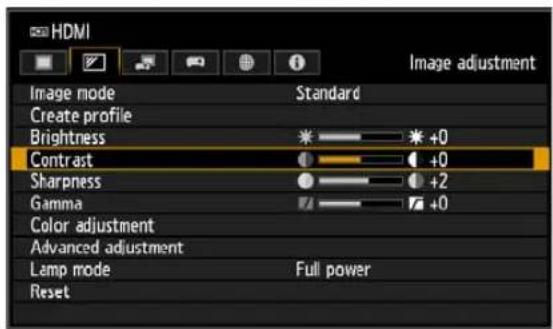
Example: Contrast (P135)
- Select [Contrast].
- Use the [ ]◀ [ ] ▶buttons to adjust the setting.
Selecting from a different screen (1)
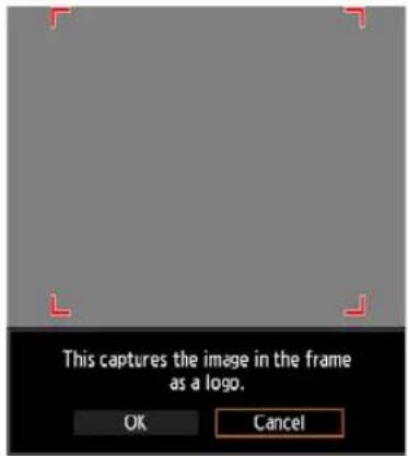
Example: Logo capture (P154)
- Select [Logo capture].
- Press the OK button to display a different screen.
- Then follow the instruction on the screen.
Selecting from a different screen (2)
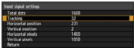
Example: Tracking (P128)
- Select [Input signal settings].
- Press the OK button to display a different screen.
- Use the [ ] ▲ [ ] Buttons to select [Tracking].
- Use the [ ]◀ [ ] ▶buttons to select the value.
5Pressing the MENU button causes the menu screen to disappear. The menu screen will also disappear if the EXIT button is pressed.
The menu screen is divided into 6 tabs as shown below.
![[Input settings] tab (P126) You can set the type of signal or the method of projection of the images input. [Image adjustment] tab (P134) You can adjust the image quality and colors according to your preference. [Install settings] tab (P142) This setting is used when installing the projector. [System settings] tab (P153) You can set the operation of the projector. [Network settings] tab (P173) These settings are for when using the projector from a PC via a network. [Information] tab (P188) You can check information about the signal types of the images projected and other information. HDMI Aspect Input level Super white Color space Progressive PC-free multi projection Split screen Input signal details Contents of menu Auto Auto Off Auto Off Menu items](/content/2026/05/965391/images/e51dce385922fb6033f180473f91d8a4f344ed4cd33d35888ec2d74911173547.jpg)
Input settings (P126)
| Menu Option | Submenu Details | |||
| Aspect Auto*, 16:10 (1) | 16:9 (2), 4:3 (2), Zoom (3), True size (2) P127 | |||
| Auto PC (4) P127 | ||||
| Input signal select (4) P127 | ||||
| Input signal settings (4) | Total dots, Tracking, Horizontal position, Vertical position, Horizontal pixels, Vertical pixels | P128 | ||
| Input level (5) Auto*, No | normal, Expanded P129 | |||
| Super white (5) Off, On* | P129 | |||
| Color space (5) Auto*, RGB, YCbCr P129 | ||||
| Progressive (3) Off, Film/auto*, Video 1, Video 2, 25p/30p(PsF) P130 | ||||
| Slideshow interval (6) | [--:--] | P130 | ||
| Animation effect (6) | Off*, Cross fade, Fade out/in | P130 | ||
| PC-free multi projection | Mode setting | Off*, Primary, Secondary | P131 | |
| Layout pattern setting | Total number, Layout pattern | P131 | ||
| Destination projector setting | IP address, Confirm, Enter | P131 | ||
| Slideshow interval | [--:--] | P132 | ||
| Animation effect | Off*, Cross fade, Fade out/in | P132 | ||
| Split screen | Off*, On | P132 | ||
| Settings | Split screen | Off*, On | ||
| Control rights | Left screen*, Right screen | |||
| Swap right-left | Yes, No | |||
| Layout | Mode 3-7, Mode 5-5, Mode 7-3 | |||
| Input signal details (5) | Format information, Color/Range information, DP Link information | P133 | ||
*: Factory default, or state after [Factory defaults] is executed.
Displayed for the following input signals.
(1): HDMI, DisplayPort, Digital PC, Analog PC, HDBaseT
(2): HDMI, DisplayPort, Digital PC, Analog PC, Component, HDBaseT
(3): HDMI, DisplayPort, Component, HDBaseT
(4): Analog PC
(5): HDMI, DisplayPort, HDBaseT
(6): USB
Image adjustment (P134)
| Menu Option / Submenu Details | ||||
| Image mode | Standard*, Presentation, Dynamic, Video, Photo/sRGB, DICOM SIM, User 1 – 5 | P135 | ||
| Create profile / Save profileBaseline image mode | User 1, User 2, User 3, User 4, User 5 | P135 | ||
| Brightness | P135 | |||
| Contrast | P135 | |||
| Sharpness | P136 | |||
| Gamma | P136 | |||
| Color adjustment | Color level, Color balance, Color temperature, R Gain, G Gain, B Gain, R Offset, G Offset, B Offset | P136 | ||
| Advanced adjustment | Ambient light (7) | Off* | P137 | |
| Adjust | Type, Level | |||
| Random noise reduction (8) | Off*, Low, Middle, High | P137 | ||
| MPEG noise reduction (8) | Off*, Low, Middle, High | P138 | ||
| Mosquito noise reduction (9) | Off*, Low, Middle, High | P138 | ||
| Dynamic gamma (*1) | Off*, Low, Middle, High | P138 | ||
| Menu | Option / Submenu | Details | ||
| Advanced adjustment | Colorimetry (10) Auto*, BT.709, BT.2020 P138 | |||
| Mem. color correct (*1) | Flesh | Off*, Weak, Middle, Strong | P139Sky | |
| Off*, Weak, Middle, Strong | ||||
| Green | Off*, Weak, Middle, Strong | |||
| 6-axis color adjust Off*, Adjust P139 | ||||
| Fine-Tune Gamma (11) Off*, Adjust P140 | ||||
| Lamp control Off*, On P140 | ||||
| Lamp mode Full power*, Power saver 1, Power saver 2 P141 | ||||
| Reset OK, Cancel | P141 | |||
| Image priority (in split-screen mode) | Primary*, Secondary | P141 | ||
*: Factory default, or state after [Factory defaults] is executed.
Under the following setting, differs from factory defaults.
(*1): [Weak] when image mode is [Dynamic]
Displayed under the following conditions.
(7): When image mode is [Photo/sRGB]
(8): When the input signal is not LAN or USB
(9): When the input signal is LAN or USB
(10): When image mode is [Video]
(11): When image mode is not [DICOM SIM]
Install settings (P142)
| Menu | Option / Submenu | Details | ||
| Positional lock | Off*, On | P143 | ||
| Image flip H/V | None*, Ceiling mounted, Rear, Rear, Ceiling mounted | P143 | ||
| Screen aspect | 16:10*, 16:9, 4:3, 16:9 D. image shift, 4:3 D. image shift | P144 | ||
| Zoom | P144 | |||
| Keystone | Horizontal-vertical keystone*, Corner adjustment | P145 | ||
| Reset | OK, Cancel | |||
| Digital image shift | P145 | |||
| Professional settings | RGB alignment | Micro-digital image shift | Off*, Adjust | P146 |
| Registration | Off*, Adjust | |||
| High altitude | Off*, On P147 | |||
| Lens shift mode | Normal*, Expanded | P147 | ||
| Marginal focus | Off* | P147On | ||
| Reset | ||||
| Edge blending | Off* | P148 | ||
| Adjust | Side, Left, Right, Top, Bottom, Color blending adjustment, Black level adjustment, Marker, Corner adjustment, Reset | |||
| Menu Option / Submenu Details | ||||
| Lens - Position | Load position 1 – 3 | P151 | ||
| Save position 1 – 3 | ||||
| Lens shift reset | Preset positions | XX% (12), 0% | ||
| OK | ||||
| Screen color | Normal* | P152 | ||
| Greenboard | ||||
| Adjust | R Gain, G Gain, B Gain, R Offset, G Offset, B Offset | |||
| Test pattern | Off* | P152 | ||
| On | ||||
*: Factory default, or state after [Factory defaults] is executed.
(12): XX% indicates the preset position of the installed lens.
System settings (P153)
| Menu Option / Submenu Details | ||||
| User screen settings | Logo capture OK, Cancel P154 | |||
| Logo position | Upper L, Upper R, Center*, Lower L, Lower R | P154 | ||
| No signal screen Black, Blue*, User | ogo P154 | |||
| Screen when blank Black*, Blue, User logo P154 | ||||
| Projector on Skip, Canon logo*, User logo P155 | ||||
| On screen | Menu position | Upper L, Upper R, Center*, Lower L, Lower R | P155 | |
| Menu display time Normal*, Extended P155 | ||||
| Guide Off, On* P156 | ||||
| Show input status Off, On* P156 | ||||
| NMPJ standby guide display | Off, On* P157 | |||
| Split screen ID display | Off, On* P157 | |||
| Lamp warning display | Off, On* P157 | |||
| Air filter warning display | Off, On* P157 | |||
| Overheat warning display | Off*, On P157 | |||
| Remote control/Side control | Beep | Off, On* P158 | ||
| Key repeat | Off, On* P158 | |||
| Key lock | Off*, Main unit, Remote (wireless) | P158 | ||
| IR receiver settings | All*, Front, Rear | P159 | ||
| Remote control channel | Ch1, Ch2, Ch3, Ch4, Independent* | P159 | ||
| [INPUT A-C] button settings | INPUT A | Disable, HDMI*, DisplayPort, Digital PC, Analog PC-1, Analog PC-2, Component, HDBaseT, LAN, USB | P160 | |
| INPUT B | Disable, HDMI, DisplayPort*, Digital PC, Analog PC-1, Analog PC-2, Component, HDBaseT, LAN, USB | |||
| INPUT C | Disable, HDMI, DisplayPort, Digital PC, Analog PC-1, Analog PC-2*, Component, HDBaseT, LAN, USB | |||
| [Fn] button settings Disable*, Split screen P160 | ||||
| Menu | Option / Submenu | Details | ||
| Audio in terminal select | HDMI Off, Audio in, HDMI* | P160 | ||
| DisplayPort Off, Audio in, DisplayPort* | ||||
| Digital PC Off, Audio in* | ||||
| Analog PC-1 Off, Audio in* | ||||
| Analog PC-2 Off, Audio in* | ||||
| Component Off, Audio in* | ||||
| HDBaseT Off, Audio in, HDBaseT* | ||||
| LAN Off, Audio in, LAN* | ||||
| USB Off, Audio in* | ||||
| HDBaseT signal quality P161 | ||||
| Extron XTP | Off*, On P161 | |||
| Serial communication | Service port*, HDBaseT | P161 | ||
| Detail | Baud rate, Data bits, Parity | |||
| Stop bit 1*, 2 | ||||
| Power supply settings | Standby power setting Normal, Low-power* P162 | |||
| Power management mode | Disabled, Light source off, Standby* | P162 | ||
| Power management duration | 5 min., 10 min., 15 min.*, 20 min., 30 min., 60 min. | P163 | ||
| Direct power on | Off*, On | P163 | ||
| Motion blur reduction | Off*, Weak, Strong | P163 | ||
| Language | English*, Deutsch, Français, Italiano, Español, Português, Svenska, Русский, Nederlands, Suomi, Norsk, Türkçe, Polski, Magyar, Čeština, Dansk, إنجليزی, 中文简体, 中文繁體, 한국어, 日本語 | P164 | ||
| Other settings | Password settings | Off*, On | P165 | |
| Register password | P166 | |||
| Date and time settings | Date and time | P166 | ||
| Date display format | Year/month/date, Month/date/year, Date/month/year | |||
| Daylight saving time | Off*, On, Edit | |||
| Region, Time zone | ||||
| SNTP | Off, On (IPv4), On (IPv6) | |||
| Schedule | Default | Off*, On, Edit | P167 | |
| Special period 1 – 5 | Off*, On, Edit | |||
| Gamma restore | Off*, Adjust | P170 | ||
| Lamp counter | Reset | Yes, No | P171 | |
| Air filter counter | Reset | Yes, No | P171 | |
| Power counter | P171 | |||
| Firmware | Yes, No | P171 | ||
| Factory defaults | OK, Cancel | P172 | ||
*: Factory default, or state after [Factory defaults] is executed.
Network settings (P173)
| Menu | Option / Submenu | Details | ||
| Network settings lock | Unlock | Password input | P174 | |
| Lock* | ||||
| Network password setting | Off, On* P174 | |||
| Register network password | Password input | P174 | ||
| Network (wired/ wireless) | Off/Off*, On/Off, On/On (Pj AP), Off/On (Pj AP), Off/On (Infra) | P175 | ||
| Detailed settings (wired) | MAC address | P176 | ||
| Detailed IPv4 address settings | IP address, Subnet mask, Gateway address | |||
| DHCP Off*, On | ||||
| TCP/IP settings | IP address, Subnet mask, Gateway address | |||
| IPv6 Off*, On | P177 | |||
| Detailed IPv6 address settings | Link local, Auto <1> - <5>, Manual, Gateway | |||
| Auto settings Off, On* | ||||
| Manual settings | IP address, Prefix length, Gateway address | |||
| Network setting initialization Yes, No | P179 | |||
| Detailed settings (wireless) | Mode, SSID, Security, Channel, Signal strength, MAC address | P180 | ||
| Wi-Fi Protected Setup | PBC OK, Cancel | |||
| PIN OK, Cancel | ||||
| Manual settings | Mode | |||
| SSID | Update SSID 1 - 14 SSID input Manual SSID input | |||
| Security | Open, WEP, WPA2 AES, WPA/WPA2 TKIP/AES | |||
| Channel | ||||
| Key ID 1, 2, 3, 4 | ||||
| Key type ASCII, HEX | ||||
| Key | ||||
| Detailed IPv4 address settings | IP address, Subnet mask, Gateway address | P182 | ||
| DHCP Off*, On | ||||
| TCP/IP settings | IP address, Subnet mask, Gateway address | |||
| IPv6 Off*, On | ||||
| Detailed IPv6 address settings | Link local, Auto <1> - <5>, Manual, Gateway | |||
| Auto settings Off, On* | ||||
| Manual settings | IP address, Prefix length, Gateway address | |||
| Network setting initialization Yes, No | ||||
| PJLink Off, On* P185 | ||||
| AMX Device Discovery | Off*, On P186 | |||
| Crestron RoomView Off*, On P186 | ||||
| Information | E-mail sender address | P187 | ||
| E-mail recipient address | ||||
| Detailed information (wired) | IPv4 | |||
| IPv6 | Link local, Auto, Manual | |||
| Detailed information (wireless) | IPv4 | |||
| IPv6 | Link local, Auto, Manual | |||
*: Factory default, or state after [Factory defaults] is executed.
Information (P188)
| Menu |
| Model name |
| Input signal |
| Firmware |
| Serial no. |
| Projector usage time |
| IP address (wired) |
| IP address (wireless) |
| Projector name |
| Comments |
| System information ID |
*: Factory default, or state after [Factory defaults] is executed.

The following settings are not reset even when factory defaults are restored.
- Selected input signal
• [Image adjustment] - Save profile
- Baseline image mode
- Fine-Tune Gamma (saved value)
• [Install settings]
- Lens - Position
- High altitude
- Lens shift mode
- Marginal focus (setting value)
- Registration
- [System settings]
- Remote control channel
- Extron XTP
- Serial communication (Stop bit)
- Standby power setting
- Language
- Date and time settings
- Schedule
- Gamma restore
- Lamp counter
- Air filter counter
- Power counter
- Firmware
• [Network settings]
• [Information]
Menu Description
Input settings
This section describes settings for aspect ratio, resolution, and projection from a USB flash drive.
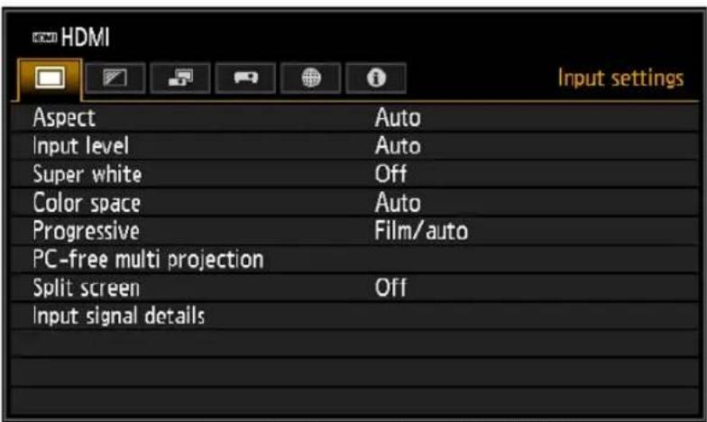
Menu screen when the input signal is HDMI
| Menu Function | Details | |
| Aspect Select an image as | aspect ratio. P127 | |
| Auto PC | Automatically adjusts display position misalignment and screen flickering. | P127 |
| Input signal select Manually set a resolution to suit computer images. P127 | ||
| Input signal settings Complete input signal settings. P128 | ||
| Input level | Select the input level for HDMI, HDBaseT or DisplayPort signals. | P129 |
| Super white | Select super white mode for HDMI, HDBaseT or DisplayPort signals. | P129 |
| Color space | Select the color space for HDMI, HDBaseT or DisplayPort signals. | P129 |
| Progressive | Select progressive processing for still images in cinematic content or moving images in videos. | P130 |
| Slideshow interval | Specify how long individual images on a USB flash drive are projected in slideshows. | P130 |
| Animation effect | Specify the transition between images on a USB flash drive in slideshows. | P130 |
| PC-free multi projection | Specify settings for projecting images on a USB flash drive to multiple networked projectors. | P131 |
| Split screen Project two input images side by side. P132 | ||
| Input signal details | Shows input signal details for each input terminal used. | P133 |
Menus that are not available are grayed out or hidden.
Aspect

[Input settings] > [Aspect]
Select a projection aspect ratio for images.
The ASPECT button on the remote control can also be used to select the [Aspect] settings.
| Option Function | |
| Auto | An image is projected at the aspect ratio of the input signal. Suitable for most projection. |
| 16:10 The image is projected using an input signal aspect ratio of 16:10. | |
| 16:9 The image is projected using an input signal aspect ratio of 16:9. | |
| 4:3 The image is projected using an input signal aspect ratio of 4:3. | |
| Zoom | This cuts the upper/lower or left/right part of the screen according to the screen aspect and zooms in or out of the center of the image. |
| True size | The image is projected with the original resolution of the input signal. |
Menus that are not available are grayed out or hidden.

- For LAN and USB input, [Auto] is selected automatically.
- Different contents are displayed for different screen aspects or input signal types.
- A screen aspect setting of [16:10] cannot be selected for component signals.
Auto PC

[Input settings] > [Auto PC]
Automatically adjusts display position misalignment and screen flickering when the input signal is [Analog PC-1] or [Analog PC-2].

If the Auto PC adjustment is insufficient, perform the following operations.
- Select the input signal that matches the computer resolution from [Input signal select].
- If adjustment remains insufficient, adjust [Total dots], [Tracking], [Horizontal/Vertical position] and [Horizontal/Vertical pixels] in [Input signal settings] (P128).
- For supported signals, see the table on page 214 – 215.
Input signal select

[Input settings] > [Input signal select]
Select a suitable resolution if Auto PC does not project computer images correctly when the input signal is [Analog PC-1] or [Analog PC-2].
Select the input signal that matches the computer resolution. Press the OK button to confirm the setting, and then press the MENU button.

For supported signals, see the table on page 214 - 215.
Input signal settings

[Input settings] > [Input signal settings]
Complete input signal settings when the input signal is [Analog PC-1] or [Analog PC-2]. Use the [◀/ [ ]buttons to adjust the levels as needed.
Perform this adjustment if the Auto PC function (P127) cannot adjust the projected image correctly.
| Input signal settings | |
| Total dots | 1688 |
| Tracking | 32 |
| Horizontal position | 231 |
| Vertical position | 2 |
| Horizontal pixels | 1400 |
| Vertical pixels | 1050 |
| Return | |
| Submenu Function | |
| Total dots | Adjust the total number of horizontal dots. Adjust it when stripes are displayed on the screen. |
| Tracking | Fine-tune the timing of image generation from signals. Adjusts the tracking when the image distorts or flickers. |
| Horizontal position | Adjust the horizontal image position to correct horizontal misalignment. |
| Vertical position Adjust the vertical image position to correct vertical misalignment. | |
| Horizontal pixels Adjust the horizontal image resolution. | |
| Vertical pixels Adjust the vertical image resolution. | |
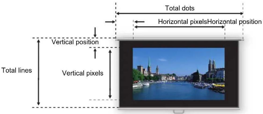
Input level

[Input settings] > [Input level]
Adjust the input level for content projected via HDMI, HDBaseT or DisplayPort.
| Option Function |
| Auto Automatically switches the input level based on the input signal. |
| Normal Limits the input level to 16 – 235. |
| Expanded Enables a full input level of 0 – 255. |

- You can select this only when the type of signal sent from AV equipment is RGB.
- In [Auto] mode, the signal level is selected automatically. (Some AV equipment and HDBaseT transmitters may not support this.)
- If your AV equipment HDMI output can be set to [Normal] or [Expanded], we recommend [Expanded]. The contrast of images will be improved and dark scenes will be rendered more realistically. In this case, set [Input level] to [Auto] or [Expanded]. For more detailed information, refer to the user's manual for the AV equipment connected to the projector.
Super white

[Input settings] > [Super white]
Select to project white signals in HDMI, HDBaseT or DisplayPort input that are in a range of 16 – 235 at 100% – 109% brightness (235 – 255).
| Option Function | |
| Off | Disable super white.Project white signals with an input level of 235 at 100% brightness. All white signals with an input value exceeding 235 are also projected at 100% brightness. |
| On | Convert input signals in a range of 16 – 235 so that an input level of 255 is projected as white 109% at 100% brightness. |

- Super white has no effect when [Input level] is set to [Expanded].
- Set this option to [Off] if projection looks distorted or unnatural when it is [On].
- Setting this option to [On] will darken the overall image.
Color space

[Input settings] > [Color space]
Select the color space for HDMI, HDBaseT or DisplayPort signals.
| Option Function | |
| Auto Selects the optimal color format for input signals. | |
| RGB Forces the projector to handle the input signal as an RGB signal. | |
| YCbCr | Forces the projector to handle the input signal as a color difference signal. |
Progressive

[Input settings] > [Progressive]
Performs progressive processing optimized for still images in cinematic content or moving images in videos, when interlaced HDMI signals are supplied.
| Option Function | |
| Off Does not perform | progressive processing. |
| Film/auto | Suitable for still images or typical moving images. Performs progressive processing for video or cinematic content. |
| Video 1 | Suitable for projecting video with high image quality and relatively slow movement. Performs progressive processing optimized for HD video. |
| Video 2 | Suitable for projecting video with faster movement. Performs progressive processing optimized for fast-moving video. |
| 25p/30p(PsF) | Performs progressive processing optimized for 1080 PsF/25 or 1080 PsF/30 video (25 or 30 fps, respectively). |

- Select [Off] when flickers and horizontal lines are noticeable in media that has a lot of fast-moving action.
- Not available in split-screen mode.
Slideshow interval

[Input settings] > [Slideshow interval]
You can project images on a USB flash drive automatically, one after another. Use the [◀/ [ ]buttons to set the interval after which images are switched in a range of 1 seconds to 60 minutes, in the format min.:sec.

- Switching the input signal to an option other than [USB] will stop any slideshow in progress. To resume the slideshow from the last image shown, return the input signal to [USB].
- If you use digital zoom during a slideshow, the digital zoom will be cancelled when you switch to the next image.
Animation effect

[Input settings] > [Animation effect]
Specify the transition for slideshows of images on a USB flash drive.
| Option Function | |
| Off Disable slideshow transitions. | |
| Cross fade Fade out | one image as the next image fades in. |
| Fade out/in Fade out | one image to black, and then fade the next image in. |
PC-free multi projection

[Input settings] > [PC-free multi projection]
Specify settings when projecting images on a USB flash drive to multiple networked projectors. For instructions, see "Using PC-Free Multi Projection" (P112).
| PC-free multi projection | |
| Mode setting | Primary |
| Layout pattern setting | 2x2 |
| Destination projector setting | |
| Slideshow interval | --:-- |
| Animation effect | Off |
| Return | |
Mode setting
Specify the mode for PC-free multi projection: Primary ^1 or Secondary ^2 mode.
*1 Connect a USB flash drive and stream images for projection to Secondary projectors.
*2 Project images streamed from the Primary projector.
| Option Function |
| Off Disable PC-free multi projection. |
| Primary Projection in Primary mode. |
| Secondary Projection in Secondary mode. |

Before specifying the mode, confirm that you are using a wired network connection and that [Network (wired/wireless)] is set to [On/Off] or [On/On (Pj AP)] (P175).
Layout pattern setting
Specify the total number of projectors and the layout pattern (P113).
| Option Function | |
| Total number | Specify the total number of projectors, including all Primary and Secondary projectors. 2 – 9 projectors can be specified. |
| Layout pattern | Select a layout pattern. Images from the Primary projector are streamed to the upper left in the layout pattern. |
Destination projector setting
Specify IP addresses of projectors set to Secondary mode.
| Option Function | |
| IP address | Enter the IP address of destination projectors. The projector in Primary mode is identified as [1]. The wired IP address specified in [Network settings] is displayed. |
| Confirm | Stream projection to the Secondary projector with the corresponding number (2 – 9), as specified in the IP address field. |
| Enter Confirm the IP address of destination projectors. | |
Slideshow interval
Specify the interval after which slideshow images are switched. Enter the time in a range of 5 seconds to 10 minutes, in the format min.:sec.
This setting is available when the mode is set to [Primary].

If the projector is turned off and then on again during a slideshow in PC-free multi projection mode, the slideshow automatically resumes from the first image in the folder last used for projection.
Animation effect
Specify the animated slideshow transition.
This setting is available when the mode is set to [Primary].
| Option Function | |
| Off Disable slideshow transitions. | |
| Cross fade Fade out one image as the next image fades in. | |
| Fade out/in Fade out one image to black, and then fade the next image in. |
Split screen

[Input settings] > [Split screen]
Two input images from devices connected to the projector can be projected side by side.
| Option Function | ||
| Off Exit split-screen | mode. | |
| On Activate split-screen | green mode. | |
| Settings | ||
| Submenu Function | ||
| Split screen Switch between normal and split-screen projection. | ||
| Control rights | Select the image to control. When the left image is selected, [1] is displayed, and when the right image is selected, [2] is displayed. | |
| Swap right-left | Switch the sides that images are projected on. | |
| Layout | Mode 3-7 Use 30% of the screen width for the left side and 70% for the right. | |
| Mode 5-5 Use 50% of the screen width for the left side and 50% for the right. | ||
| Mode 7-3 Use 70% of the screen width for the left side and 30% for the right. | ||

- Control can be switched to the other side by pressing the [ ]◀[ ] ▶ the remote control when △()◀ ( ) is displayed in the center of the image area.
- When you switch to split-screen display, the left and right signals and input status are shown in the input window.
For details on split-screen mode, see "Projecting Two Images Side by Side" (P58).
Input signal details

[Input settings] > [Input signal details]
Shows details about video signals supplied to the selected input terminal. This menu is displayed for HDMI, DisplayPort, or HDBaseT input.
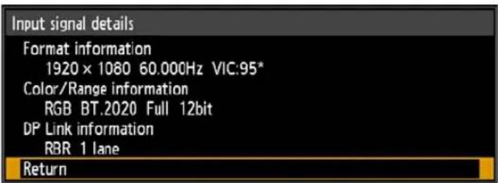
As format information, the resolution, frequency, and Video Identification Code (VIC) are indicated.
As color information, the color format/subsampling and color space are indicated. As range information, the range and depth are indicated.
Additionally, for DisplayPort video signals, DPLink information (rate and number of lanes) is indicated.
Image adjustment
This section describes image quality settings such as brightness, contrast, and sharpness.
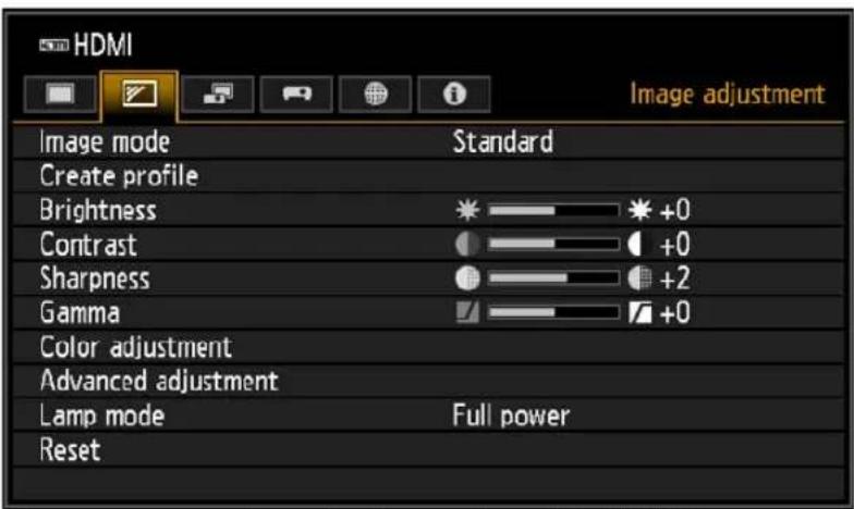
Menu screen when the input signal is HDMI
| Menu Function | Details | |
| Image mode* | Select overall image quality to suit the projected image. | P135 |
| Create profile / Save profile | Save desired image quality settings as profiles. P135 | |
| Baseline image mode Shows the image mode that is basis of the profile. P135 | ||
| Brightness* Adjust image brightness. P135 | ||
| Contrast* Adjust image contrast. P135 | ||
| Sharpness* Adjust image sharpness. P136 | ||
| Gamma* Correct loss of detail in shadows or highlights. P136 | ||
| Color adjustment* Fine-tune image colors. P136 | ||
| Advanced adjustment* | Fine-tune noise reduction and color tone. | P137 |
| Lamp mode* | Select the lamp brightness. | P141 |
| Reset | Restore default image settings. | P141 |
| Image priority* | Select which side is the basis for image processing in split-screen mode. | P141 |
Menus that are not available are grayed out or hidden.
* Any adjustments you make are stored for each combination of input signal and image mode.
Image mode

[Image adjustment] > [Image mode]
Select the overall image quality for projected images. Can also be selected by pressing the IMAGE button on the remote control (P36).
| Option Types of Images Effect | ||
| Standard | Computer screens, or media played with video software | Bright overall; white, with natural colors |
| Presentation Images mainly consisting of text Bright overall | ||
| Dynamic Video content | Bright overall | |
| Video Video from camcorders | Somewhat dark; colors resemble TV | |
| Photo/sRGB | Digital photos from sRGB-compatible cameras | Somewhat dark; conforms to the sRGB standard |
| DICOM SIM | Medical or other monochrome images | Conforms to DICOM Standard Part 14. However, the projector cannot be used in diagnosis or similar applications. |
| User 1 – 5 | Up to five user profiles can be stored for your selected image quality settings. Stored profiles are available in this setting as an image mode. | |
Menus that are not available are grayed out or hidden.

You can adjust the image quality by adjusting the following items in each image mode: [Brightness], [Contrast], [Sharpness], [Gamma], [Color adjustment], [Advanced adjustment], and [Lamp mode]
Create profile

[Image adjustment] > [Create profile]
Save desired image quality settings in up to five user profiles.

- The saved settings are [Brightness], [Contrast], [Sharpness], [Gamma], [Color adjustment], [Advanced adjustment], and [Lamp mode].
- The image mode name which was the basis for the settings change is also saved in the user profile. When a user profile is selected as the image mode, the image mode that was the basis for that user profile is displayed in the menu as [Baseline image mode].
Brightness

[Image adjustment] > [Brightness]
Adjust image brightness.
Contrast

[Image adjustment] > [Contrast]
Sharpen or soften image contrast.
Sharpness

[Image adjustment] > [Sharpness]
Adjust image sharpness.
Gamma

[Image adjustment] > [Gamma]
Correct image areas that are too dark or too bright to see clearly.

For more detailed adjustment, use "Fine-Tune Gamma" (P140).
Color adjustment

[Image adjustment] > [Color adjustment]
Adjust color-related settings such as color level, color balance, and color temperature.
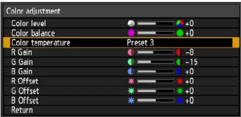
| Submenu Function | |
| Color level Adjusts the intensity of colors. | |
| Color balance Adjusts the color balance of a purplish or greenish image. | |
| Color temperature Adjusts the white color temperature. | |
| R / G / B Gain Adjust the gain of each color. | |
| R / G / B Offset Adjusts the color offset of each color. | |

In [DICOM SIM] image mode, [Color temperature] is not adjusted with numeric values but set to one of the following five presets.
Preset 1: Prioritize brightness, relative to DICOM Standard Part 14.
Preset 2: Prioritize color tone, relative to DICOM Standard Part 14.
Preset 3: Adjust color to conform to DICOM Standard Part 14.
Preset 4: Reproduce colors of X-ray film (Clear base).
Preset 5: Reproduce colors of X-ray film (Blue base).
Advanced adjustment

[Image adjustment] > [Advanced adjustment]
Fine-tune noise reduction and color tone.
| Advanced adjustment | |
| Ambient light | Off |
| Random noise reduction | Off |
| MPEG noise reduction | Off |
| Dynamic gamma | Off |
| Mem. color correct | |
| 6-axis color adjust | Off |
| Fine-Tune Gamma | |
| Lamp control | Off |
| Return | |
Ambient light
Minimize the effect of ambient light on the screen.
| Option Function | |||
| Off Projects an image with no correction. | |||
| Adjust | Type | Tungsten | For ambient light from conventional light bulbs or fluorescent light of this color. |
| Fluorescent | For ambient light from a “day white” fluorescent source. | ||
| Level | L | For an ordinary brightness of ambient light. | |
| H For bright ambient light. | |||
Examples of Ambient Light Level Settings
| Level Example Location | |
| L Projection room, sports bar, etc. | |
| H Conference room, lecture room, etc. |

[Ambient light] is available when the image mode is [Photo/sRGB] (P135).
Random noise reduction
Reduce random image noise*.
* Effective on noise with an irregular frequency or amplitude.
| Option Function | |
| Off Disables random noise reduction. | |
| LowMiddleHigh | Specify one of three levels of intensity of the random noise reduction. |

- Select [Low] for fast-moving images or [High] for slow-moving images.
- This setting is not displayed for LAN or USB input.
MPEG noise reduction
Reduce MPEG image noise*.
* Block noise resembles pixelation and may affect either on JPEG images or in MPEG video.
| Option Function | |
| Off Disables MPEG noise reduction. | |
| LowMiddleHigh | Specify one of three levels of intensity of the MPEG noise reduction. |

This setting is not displayed for LAN or USB input.
Mosquito noise reduction
Reduce mosquito noise*.
* A type of noise affecting image edges or areas where colors change significantly, either on JPEG images or in MPEG video.
| Option Function | |
| Off Disables mosquito noise reduction. | |
| LowMiddleHigh | Specify one of three levels of intensity of the mosquito noise reduction. |

This setting is not displayed for HDMI, HDBaseT, DisplayPort, Digital PC, Analog PC-1, Analog PC-2, or Component input signals.
Dynamic gamma
You can adjust the gradation representation of light and dark portions of an image automatically.
| Option Function | |
| Off Disable dynamic gamma adjustment. | |
| LowMiddleHigh | Specify one of three levels of dynamic gamma adjustment. |
Colorimetry
Select the input color space.
| Option Function | |
| Auto | Automatically determine the optimal color space (BT.709 or BT.2020) based on input signals. |
| BT.709 Forces use | of the BT.709 color space. |
| BT.2020 Forces use | of the BT.2020 color space. |

[Colorimetry] can only be set when the image mode (P135) is [Video].
Mem. color correct
Enhances skin tones, blue skies, and greens, so that these colors are more consistent with people's remembered impressions.
| Submenu Function | ||
| FleshSkyGreen | Off Disable | e correction. |
| WeakMiddleStrong | Specify the level of correction. | |
6-axis color adjust
Fine-tune RGB (red, green, blue) and CMY (cyan, magenta, yellow) hues in images.
| Option Function | |
| Off Disables 6-axis color adjustment. | |
| Adjust | 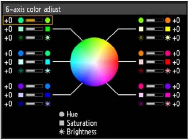 Use the [▲/ [ ]▼buttons to select [ Hue], [ Saturation], or [Brightness], and use the [ ] / [ ] buttons for adjustment.When you are finished adjusting the color, press the OK button.Adjustment is not applied to the projected menu itself. Use the [▲/ [ ]▼buttons to select [ Hue], [ Saturation], or [Brightness], and use the [ ] / [ ] buttons for adjustment.When you are finished adjusting the color, press the OK button.Adjustment is not applied to the projected menu itself. |
| Reset Returns all adjustment values to zero. | |
Fine-Tune Gamma
Adjust white, red, green, and blue gamma curves. Red, green, and blue can be adjusted separately. Adjustments to white are also applied to the three other colors. Note that adjusting any color will overwrite previous adjustments.
Adjustment values can also be saved or loaded by selecting [Save/Load].
Use the [▲] / [▼] buttons to select a color, and then press the OK button.
Next use the [ ]/ [ ]buttons to select a point on the gamma curve, and then use the [ ] / ▲
[▼] buttons to adjust the position of the point. When adjustment is finished, press the OK
button to confirm the setting.
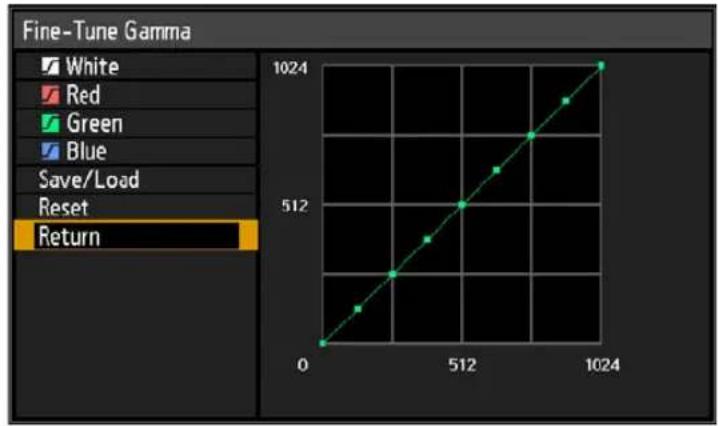
line
Fine-Tune Gamma | X-axis | Y-axis | |---|---| | 0 | 0 | | 512 | 512 | | 1024 | 1024 |
- [Fine-Tune Gamma] is available in image modes other than [DICOM SIM].
- For details on gamma correction, see "Gamma" (P136).
- Use input signals or a test pattern for adjustment.
- Adjustment is not applied to the projected menu itself.
- Up to five adjustment values can be saved.
Lamp control
Dims the lamp automatically when the input signal is completely black.
| Option Function | |
| Off No lamp control. | |
| On | Dims the lamp in response to fully black input signals. Normal brightness is restored once the input signal changes from fully black. |
- The projector automatically enters standby mode if the lamp is dimmed (that is, if the input signal is fully black) for more than one hour. A countdown window is displayed 10 minutes before entering standby.
- The lamp is not dimmed when projection is blanked, when no signals are supplied, or when black is projected during gamma restore.
- Lamp control is not available for the following settings:
- In split-screen mode
- During test pattern projection
- When [Lamp mode] is set to [Power saver 1] or [Power saver 2]
- When [High altitude] is set to [On]
- No lamp control is performed in the first 20 minutes after the projector is turned on.

- All image adjustments are stored as modified settings for the current input signal and image mode.
- Resolution may seem lower with [Random noise reduction], [MPEG noise reduction], or [Mosquito noise reduction].
Lamp mode

[Image adjustment] > [Lamp mode]
Reducing the lamp brightness reduces power consumption and cooling fan noise.
| Option Function | |
| Full power Projects | images at full brightness. |
| Power saver 1 Reduces | lamp brightness to save energy. |
| Power saver 2 Reduces | power consumption and noise even more. |
Reset

[Image adjustment] > [Reset]
Restore the current image quality settings to the factory defaults.
| Option Function | |
| OK Resets the image adjustment settings. | |
| Cancel Cancels resetting of the image adjustment settings. |

- Performing reset when [Image mode] is set to a profile from [User 1] to [User 5] will restore the settings originally saved for that user profile.
- Only the setting for the combination of input signal and image mode for the current projection is reset.
Image priority

[Image adjustment] > [Image priority]
Select which side image adjustment settings to apply in split-screen mode.
| Option Function | |
| Primary | Use the side with control rights as the [Primary] side. For image adjustment settings that are not configured separately, [Primary] side settings apply to both sides. |
| Secondary | Not available when the [Primary] side has control rights. To reverse the side given priority for image adjustment (whether on the left or right side), switch control rights to the other side and change [Secondary] to [Primary]. |

- Can be independently configured
Brightness (P135), Contrast (P135), Gamma (P136), Color adjustment (P136), Fine-Tune Gamma (P140)
• [Primary] setting also applies to [Secondary]
Image mode (P135), Advanced adjustment except Fine-Tune Gamma (P137 - P139), Lamp mode
Install settings
Adjust projection to suit the screen or the type of images, or how the projector is installed.
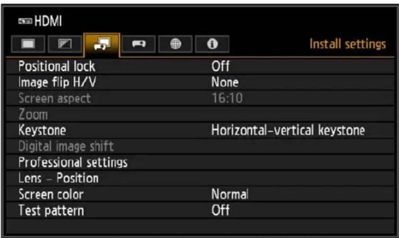
Menu screen when the input signal is HDMI
| Menu Function | Details | |
| Positional lock | Operation of installation-related functions can be prohibited. | P143 |
| Image flip H/V | Specify settings for projection from behind the screen, from the ceiling, or both. | P143 |
| Screen aspect | Select an aspect ratio that matches that of the projection screen. | P144 |
| Zoom | Digitally reduce images projected with the Short Fixed Lens (RS-SL03WF) or the Ultra-wide Zoom Lens (RS-SL06UW). | P144 |
| Keystone Set the type of keystone correction. P145 | ||
| Digital image shift Move the position of the projected image. P145 | ||
| Professional settings Specify advanced installation settings. P145 | ||
| Lens - Position | Store information about the lens position (including focus, zoom, and lens shift settings), which can be used to restore the lens to these positions. | P151 |
| Screen color Adjust projection colors to suit the screen color. P152 | ||
| Test pattern | Project a test pattern to check the resolution and color of projection during installation. | P152 |
Menus that are not available are grayed out or hidden.
Positional lock

[Install settings] > [Positional lock]
Operation of installation-related functions can be prohibited.
- Image flip H/V
- Save position (in [Lens - • Professional settings
- Screen aspect • Focus adjustment]
- Zoom
- Lens shift reset
- Lens shift adjustment
- Keystone
- Digital image shift
- Zoom adjustment
| Option Function | |
| Off The positional lock is not used. | |
| On Prevents adjustment of installation-related functions. | |
Image flip H/V

[Install settings] > [Image flip H/V]
Specify the orientation of how the projector is installed.
| Option Function | |
| None Select for normal projection, without inversion. | |
| Ceiling mounted | Select when the projector is installed upside-down on the ceiling.The projected image is inverted in both vertical and horizontal directions. |
| Rear | Select this to project an image from behind the screen.The projected image is inverted in the horizontal direction. |
| Rear, Ceiling mounted | Select this to project an image from behind the screen with the projector hung from the ceiling.The projected image is inverted in the vertical direction. |

- When mounting the projector on a ceiling, use the optional ceiling attachment (RS-CL15) and ceiling-mount arm (RS-CL17). Contact the Canon Customer Support Center for more detailed information.
- Image flipping will reset any adjustment for keystone distortion. In this case, redo the adjustment.
- Adjusting the [Image flip H/V] setting does not alter button assignments in the projector's side controls.
Screen aspect

[Install settings] > [Screen aspect]
Select an aspect ratio that matches that of the projection screen.
| Option Function | |
| 16:10 Select this when you use a screen with an aspect ratio of 16:10. | |
| 16:9 Select this when you use a screen with an aspect ratio of 16:9. | |
| 4:3 Select this when you use a screen with an aspect ratio of 4:3. | |
| 16:9 D. image shift | Select this when you use a screen with an aspect ratio of 16:9. Although keystone correction is not available in this mode, images can be shifted up or down. |
| 4:3 D. image shift | Select this when you use a screen with an aspect ratio of 4:3. Although keystone correction is not available in this mode, images can be shifted left or right. |

- Changing the screen aspect will reset any keystone or digital image shift setting.
- [Auto] may be automatically selected in [Aspect] depending on the screen aspect setting.
Zoom

[Install settings] > [Zoom]
When the Short Fixed Lens (RS-SL03WF) or the Ultra-wide Zoom Lens (RS-SL06UW) is attached and if the projected image does not fit on the screen, you can display the image by electronically reducing its size. This type of zooming reduces overall image dimensions, relative to the center of the image.
Press the [◀] button on the remote control to project images at a reduced size, and press the [▶] button to enlarge images to full size. Images can be projected at 75 – 100% of the original size.

• D.ZOOM buttons on the remote control cannot be used for this [Zoom] function.
- [Zoom] is not available when the following features are used.
- When [Keystone] is set to [Horizontal-vertical keystone]
- Split-screen mode (P58)
- Using [Zoom] after specifying corner adjustment (P145) will clear corner adjustment settings and apply the zoom setting. Instead, use [Zoom] before fine-tuning the image position with corner adjustment.
- If images still extend off the screen even after you use [Zoom], you can use corner adjustment (P145) to fine-tune the position of image corners, so that images fit on the screen.
- Switching to lenses other than the Short Fixed Lens (RS-SL03WF) or the Ultra-wide Zoom Lens (RS-SL06UW) will reset the setting to 100%.
- The zoom function is not available when [Digital PC], [Analog PC-1], or [Analog PC-2] is selected.
Keystone

[Install settings] > [Keystone]
Two types of keystone correction are available: horizontal/vertical keystone and corner adjustment. Keystone correction can also be reset. Keystone correction can also be applied by pressing the KEYSTONE button on the remote control.
| Submenu Function | |
| Horizontal-vertical keystone | Apply horizontal-vertical keystone correction. Image height and length is adjusted. |
| Corner adjustment | Apply corner adjustment. Each corner of the image can be repositioned. |
| Reset Resets the specified | keystone value. |

- Resetting the keystone value will also reset the zoom setting for the Short Fixed Lens (RS-SL03WF) or the Ultra-wide Zoom Lens (RS-SL06UW).
- The available horizontal-vertical keystone range may vary depending on the lens, zoom position, and shift position.
Digital image shift

[Install settings] > [Digital image shift]
Moves the position of the projected image.
When screen aspect is 16:9 D. image shift, move images vertically using the [▲/ [▼buttons, and for 4:3 D. image shift, move images horizontally using the [ ]◀[ ] ▶ buttons.

This cannot be selected when the screen aspect is 16:9, 16:10 or 4:3.
Professional settings

[Install settings] > [Professional settings]
Specify advanced installation settings.
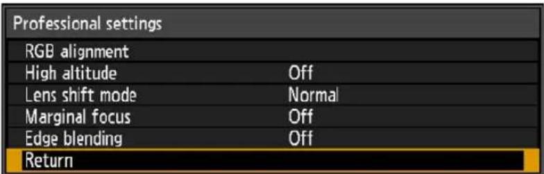
Menu screen when the Ultra-wide Zoom Lens (RS-SL06UW) is attached
RGB alignment
Correct color misalignment.
| Submenu Function | ||
| Micro-digital image shift | Use this setting to fine-tune the position of the projected image. | |
| Submenu Function | ||
| Off Does not perform micro digital image shift. | ||
| Adjust | Submenu Function | |
| Adjust | ||
| Chart | ||
| Return Return to the previous screen. | ||
| Registration | Adjusts colors that are out of alignment. You can adjust red, green and blue registration independently. | |
| Submenu Function | ||
| Off Does not perform image registration. | ||
| Adjust | Submenu Function | |
| Red / Green Blue | ||
| Chart | ||
| Return Return to the previous screen. | ||

Audio is muted while the chart is shown.
High altitude
Switch the fan mode to suit installation at low or high altitudes (above 2,300 m [7,545.8]).
| Option Function | |
| Off Setting for altitudes lower than 2,300 m (7,545.8'). | |
| On Setting for altitudes of 2,300 m (7,545.8') or higher. |

- When [High altitude] is switched, [Lamp mode] of the [Image adjustment] menu automatically changes as follows.
| High altitude Lamp mode | |
| [Off] > [On] | [Full power], [Power saver 1], [Power saver 2] > [Power saver 1] |
| [On] > [Off] | [Full power], [Power saver 1], [Power saver 2] > [Full power] |
- The changed [Lamp mode] can be changed manually in the menu.
- Changing [Lamp mode] manually may shorten the useful life of the lamp.
Lens shift mode
Switch the available lens shift range as needed.
| Option Function | |
| Normal Provides a normal lens shift range. | |
| Expanded Provides an expanded lens shift range. |

- Selecting [Expanded] may lower image quality and keystone correction precision, depending on the extent of lens shift.
- Selecting [Normal] when the lens is in the expanded range (outside the normal position) will execute lens shift reset (P151).
Marginal focus
In dome projection, image focus can be adjusted on the edges of the screen, and the remote control can be used to activate and deactivate this focus adjustment. For detailed instructions, refer to “Adjusting Peripheral Focus” (P72).
| Option Function | |
| Off Disable remote focusing of image edges. | |
| On | Enable remote focusing of image edges. To access the adjustment window, press theLENSbutton on the projector twice or press theFOCUSbutton on the remote twice. |
| Reset Restore edge focusing to the standard position. | |

- The marginal focus feature is not available depending on the type of lens installed.
- Setting this function to [Off] only prevents display of the adjustment window. Adjustment values are still retained. Use this setting to prevent remote focusing of image edges.
Edge blending
Brightness and colors of overlapping edges of images from multiple projectors, which form a blending area, can be adjusted for a more seamless appearance. For detailed instructions, see “Projecting from Multiple Projectors at Once (Edge Blending)” (P106).
| Option Function | |
| Off Disable blending. | |
| Adjust Display the menu for blending area adjustment. |
| Edge blending | ||
| Side | Width | Start position |
| Left | 0 | 0 |
| Right | 0 | 0 |
| Top | 0 | 0 |
| Bottom | 0 | 0 |
| Color blending adjustment | Off | |
| Black level adjustment | Off | |
| Marker | Off | |
| Reset | ||
| Corner adjustment | ||
| Return | ||
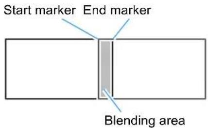
When adjusting the image projected from the right side

- Adjustment may not eliminate different colors or brightnesses in the blending area.
- For best edge-blending results, use all projectors in the same image mode and make the following adjustments.
(1) Brightness, contrast, R/G/B gain and offset, black level, blending color, color temperature, color level, color balance, sharpness, and gamma (P136)
(2) Color adjustment, by using 6-axis color adjustment (P139)
(3) Gamma adjustment, by using fine-tune gamma (P140)
(4) Corner adjustment, by using keystone correction (P145)
| Submenu Function | |||
| Side | Left / Right /Top / Bottom Select the direction of the blending area to adjust. | ||
| Width Specify the width between the start and end markers. | |||
| Start Position Moves the position of the start marker.[H2X0] • Large blending areas may cover input signal dialog boxes and other interface elements. In this case, momentarily set edge blending to [Off] and check the display.• Although the starting marker is normally aligned with the image edge, it can also be aligned toward the center of the image. In this case, the black blending area will lie outside of the starting marker. | |||
| Color blending adjustment | Adjust unwanted colors or discrepancies between colors in the blending area. | ||
| Submenu Function | |||
| Off Do not adjust colors of blended images. | |||
| Adjust | Adjust unwanted colors or discrepancies between colors in the blending area. | ||
| Option Function | |||
| White | Simultaneously adjust red, green, and blue to correct unwanted colors or discrepancies in the blending area. | ||
| Red / Green / Blue | Individually adjust red, green, and blue to correct unwanted colors or discrepancies in the blending area. | ||
| Submenu Function | ||
| Black level adjustment | Because black is lighter in the blending area than in other areas, you can adjust the black level outside the blending area to make this difference in brightness less noticeable.11) 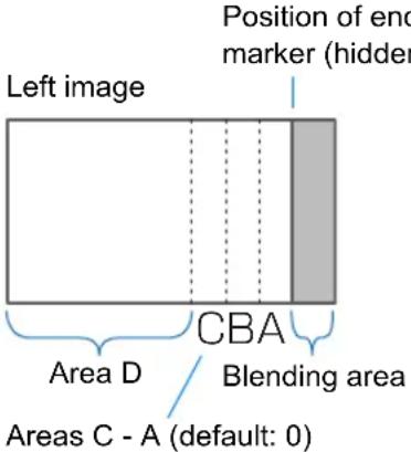 Area A: Black level cannot be adjusted.Area B: Adjust to a black level different from that of area D.Area C: Adjust to provide a smooth transition relative to the black levels of areas B and D. Area A: Black level cannot be adjusted.Area B: Adjust to a black level different from that of area D.Area C: Adjust to provide a smooth transition relative to the black levels of areas B and D. | |
| Submenu Function | ||
| Off Do not adjust the black level. | ||
| Area | Adjust areas C - A to smoothen the boundaries of the blending area. | |
| Option Function | ||
| Side Select the direction to adjust from Left / Right / Top / Bottom. | ||
| A-Width /B-Width /C-Width Adjust the widths of areas A - C. | ||
| Black level | Adjust the black level brightness and color of areas B and D. | |
| Option Function | ||
| B/D-area base Adjust the black level brightness of B/D areas. | ||
| B/D-area red /green / blue Adjust the red, green, and blue components of B/D area black levels individually. | ||
| Submenu Function | |
| Marker | Show the blending area markers. |
| Option Function | |
| Off Hide the blending area markers. | |
| On Show the blending area markers. The start marker is red, and the end marker is green. | |
| Reset Reset the marker settings. | |
| Corner adjustment | Correct image distortion by aligning corners of the blending area with the image from the reference projector. For multi-projection alignment, align the corners with the projector blending area (already adjusted) that forms the basis.Points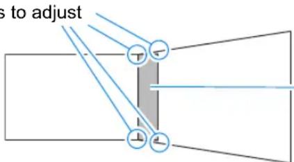 Blending area Blending area |
| Left, Right, Select the direction of the blending area to adjust. As Top, you reposition the corners of the selected area, the Bottom overall image changes to match the adjustment. | |
| Sides set to an edge-blending width of 12 or more can be adjusted when [Keystone] is set to [Corner adjustment] and the aspect ratio is [16:10].To reset adjustment, use [Keystone] (P145). | |
Lens - Position

[Install settings] > [Lens - Position]
The projector can save information about the lens position in memory. Up to three sets of lens information (including focus, zoom, and lens shift settings) can be saved, and the lens can be restored to these positions.
| Submenu Function | |
| Load position 1 – 3 | Restores the lens to the positions saved using Save position 1 – 3. |
| Save position 1 – 3 | Saves the lens position as Save position1 – 3. |
| Lens shift reset | Restores the lens to the preset position.The preset position differs depending on the type of lens.The preset position also changes when the orientation of the projector is changed, due to the ceiling mounted setting, etc.Example: [+50%, 0%] > [-50%, 0%] |

- To lock (protect) the saved position, set [Positional lock] (P143) to [On].
-
The values of the following settings are saved in addition to the lens position information (including focus, zoom, and lens shift settings):
-
Horizontal-vertical keystone / Corner adjustment
- Screen color
- Digital image shift
- Screen aspect
-
Zoom
-
[Load position] is not available unless you perform [Save position] once.
- The original lens position varies depending on the type of lens used.
- When saved lens positions are restored, images may be projected in a slightly different position than the saved position.
- Specifying a somewhat smaller image size than the screen size (image area) enables you to switch among multiple lens positions without having the image extend off the screen.
- When precise positioning is needed, use lens shift, zoom, and focus functions for fine adjustment.
Screen color

[Install settings] > [Screen color]
You can adjust the color quality of the images projected according to the color of the projection screen.
| Submenu Function | |
| Normal | Select this if a standard type of projection screen is used. The images are projected in a light quality similar to that of natural light. |
| Greenboard | Select if a dark green surface such as a blackboard is used as the screen. The color quality similar to [Normal] is obtained on the greenboard. |
| Adjust Select to fine-tune red, green and blue. | |
Test pattern

[Install settings] > [Test pattern]
You can project a test pattern (P105) to check resolution, color, and other details even without supplying an input signal. Also available by pressing the TEST PATTERN button on the remote control.
| Option Function | |
| Off Disable test pattern display. | |
| On Enable test pattern display. | |

- While the test pattern menu is displayed, you can use the [ ] [ ] buttons to switch patterns. Additionally, options of test pattern that have options can be changed with the [ ] [ ] buttons.
- The test pattern menu is no longer displayed after a little while, but you can view it again by pressing the [√] buttons.
System settings
Customize projector and remote control operation, beeping, and other details after startup, during standby, and in other situations.
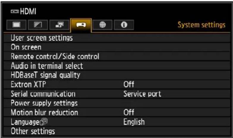
Menu screen when the input signal is HDMI
| Menu Function | Details | |
| User screen settings | Customize user screens shown at startup, when no signal is detected, and in other situations. | P154 |
| On screen | Set the display position and whether to show or hide menus, help information, and warning or caution icons. | P155 |
| Remote control/Side control | Specify operation with remote control or projector buttons. | P158 |
| Audio in terminal select Select the terminal for audio input. P160 | ||
| HDBaseT signal quality Display the video signal quality of HDBaseT input. P161 | ||
| Extron XTP | Connect to Extron XTP devices when connected to a network via HDBaseT. | P161 |
| Serial communication Display serial communication setting values. P161 | ||
| Power supply settings | Specify how power is managed at startup, in standby, and when no signal is supplied. | P162 |
| Motion blur reduction | Motion blur is blurring that occurs during video playback. Motion blur reduction can make this blurring less noticeable. | P163 |
| Language | You can select the language in which the menus are displayed. | P164 |
| Other settings | Set a password, reset counters for lamp or air filter replacement, and access other settings and information. | P165 |
Menus that are not available are grayed out or hidden.
User screen settings

[System settings] > [User screen settings]
Capture a logo and specify logo display settings.
| User screen settings | |
| Logo capture | |
| Logo position | Center |
| No signal screen | Blue |
| Screen when blank | Black |
| Projector on | Canon logo |
| Return | |
Logo capture
Registers the current image as a user logo. Registered user logos can be shown when no signal is received, when the BLANK button is pressed, or as the startup image.
| Option Function | |
| OK | Display the image for logo registration.Align the image with the red boundary lines indicating the portion that will be stored, and then press the OK button. The portion of the image within the boundary lines is now registered. |
| Cancel Cancels logo registration. | |

Only images at an aspect ratio of 16:10 can be registered as user logos.
Logo position
Specify the position of registered user logos.
You can specify the position after a logo has been registered. Choose from upper left, upper right, center, lower left, or lower right.
No signal screen
Customize the screen shown when no input signals are received.
| Option Function | |
| Black The screen is all black. | |
| Blue The screen is all blue. | |
| User logo The user logo is projected. |
Screen when blank
Select the screen shown when projection is temporarily blanked out by pressing the BLANK button on the remote control.
| Option Function | |
| Black The screen is all black. | |
| Blue The screen is all blue. | |
| User logo The user logo is projected. |
Projector on
Select a logo to project after startup until input signals can be projected.
| Option Function | |
| Skip A black screen is projected. | |
| Canon logo Displays the Canon logo that was registered in advance at the factory. | |
| User logo The user logo is projected. |
On screen

[System settings] > [On screen]
Specify display details for on-screen menus, help, and warning or precaution icons.
| On screen | |
| Menu position | Center |
| Menu display time | Normal |
| Guide | On |
| Show input status | On |
| NMPJ wait guide | Off |
| Split screen ID display | On |
| Lamp warning display | On |
| Air filter warning display | On |
| Overheat warning display | Off |
| Return | |
Menu position
Reposition menu display.
Choose from upper left, upper right, center, lower left, or lower right.

Only [Center] is available when edge blending is used. Other display positions are grayed out and not available.
Menu display time
Extend menu display from the standard 10 or 30 seconds to 3 minutes.
| Option Function | |
| Normal The menu is displayed for 10 or 30 seconds. | |
| Extended The menu is displayed for 3 minutes. |
The following display times are also changed.
| Item [Normal] [Extended] | ||
| - Menu screen- Edge blending / Corner adjustment (P148) | 30 seconds | 3 minutes |
| - Input (P45)- Keystone (P101)- Keystone reset (P104)- Focus (P46)- Zoom (P46)- Lens shift (P70)- Lens shift reset (P72)- D.image shift (P145)- D.image shift reset- Aspect (P127)- Image mode (P135)- Volume (P33, P37)- G a m m a ( P136)- Lamp mode (P141) | 10 seconds | 3 minutes |
Guide
Shows the guide screen.
| Option Function | |
| Off Hides the guide | screen. |
| On Shows the guide | screen. |

The guide screen is shown at the following cases.
- No input signal is detected.
- An invalid button is pressed in [BLANK], [FREEZE], or [D.ZOOM] mode (P36).
- When positional lock (P143) is set to [On] and buttons locked by this feature are pressed.
- When the projector is already on and the POWER button is pressed.
Show input status
Specify whether signal status is shown when there is no signal or when you are completing signal settings.
| Option Function | |
| Off The input status is not displayed. | |
| On The input status is displayed. |
NMPJ standby guide display
Specify whether to display a message when waiting for NMPJ connections.
Option Function
| Off No message is displayed during NMPJ connection standby. |
| On A message is displayed during NMPJ connection standby. |
Split screen ID display
Specify whether to show the digit (1 or 2) identifying screens in split-screen mode. Note that even if [Off] is selected, corner markers will be shown to indicate the side with control rights.
Option Function
| Off Hides the screen ID. |
| On Shows the screen ID. |
Lamp warning display
Specify whether to show a lamp replacement message after the lamp has been used for a specified period.
Option Function
| Off The prepare lamp message and the lamp warning are not displayed. |
| On The prepare lamp message and the lamp warning are displayed. |

- When it is almost time to replace the lamp, the projector's [LIGHT] indicator will flash. For details, see “LED Indicator Displays” (P34).
- Setting display to [Off] will disable both the message to prepare a replacement lamp and the warning to replace the lamp. To review the replacement timing, check the lamp counter (P171).
- Lamps that are still used after the timing for lamp replacement are more likely to rupture. Replace the lamp with a new one as soon as possible.
Air filter warning display
A message advising you to perform cleaning can be set to display when the filter needs cleaning.
Option Function
| Off The air filter warning is not displayed. |
| On The air filter warning is displayed. |

Setting [Air filter warning display] to [Off] will disable display of the warning to clean the air filter. We recommend checking the air filter counter (P171) occasionally to know when to replace the filter.
Overheat warning display
Specify whether the icon warning of high temperature (W) is shown when the internal temperature is high and the projector may overheat.
Option Function
| Off Disable high temperature warning icon display. |
| On Enable high temperature warning icon display. |
Remote control/Side control

[System settings] > [Remote control/Side control]
Specify which operations are available using buttons on the remote control or in the projector's side controls.
| Remote control/Side control | |
| Beep | On |
| Key repeat | On |
| Key lock | Off |
| IR receiver settings | All |
| Remote control channel | Independent |
| [INPUT A-C] button settings | |
| [Fn] button settings | Disable |
| Return | |
Beep
You can select whether a beep sounds or not when you operate the projector.
| Option Function | |
| Off Disables the beep. | |
| On Enables the beep. |

The beep will not sound if you mute the projector sound with the MUTE button on the remote control.
Key repeat
Key repeat enables projector or remote control buttons to be held down instead of pressing them repeatedly.
| Option Function | |
| Off Key repeat is not enabled. | |
| On Key repeat is enabled. |
Key lock
Lock the projector or remote (wireless) to prevent operation.
| Option Function | |
| Off | Disables key lock. Operation is possible on the projector or from the remote control. |
| Main unit | Operation is not possible using the projector.Use the remote control. |
| Remote (wireless) | Disables infrared remote control operations (P39). Use buttons on the projector.Operation is also possible with an optional wired remote control (RS-RC05). |
To Unlock Key Lock Function
Turn off the projector and unplug the power plug. Hold down the OK button on the projector and plug in the power cord, as you continue to hold down the OK button. In a moment, a beep will sound, and the controls will be unlocked.

When you access this setting from the projector's side controls, [Main unit] is not available. Similarly, when you access the setting from the remote control, [Remote (wireless)] is not available.
IR receiver settings
Select the infrared receiver of the projector.
| Option Function | |
| All Use both the front and the rear receivers on the projector. | |
| Front Use the front receiver on the projector. | |
| Rear Use the rear receiver on the projector. |
Remote control channel
Separate channels can be assigned to up to four projectors so that a single remote control can be used with each projector.
Selecting the Projector Channel
If a wired remote control is used, there is no need to set the remote control channel.
| Option Function | |
| Ch1 | Select the remote control channel to use with this projector. |
| Ch2 | |
| Ch3 | |
| Ch4 | |
| Independent Can be controlled from a remote control set to any channel. | |
Selecting a Channel on the Remote Control
After changing the projector channel from the menu, always change the remote control channel accordingly.
| Ch1 | Hold down both the Ch button and [1] button for 3 seconds. |
| Ch2 | Hold down both the Ch button and [2] button for 3 seconds. |
| Ch3 | Hold down both the Ch button and [3] button for 3 seconds. |
| Ch4 | Hold down both the Ch button and [4] button for 3 seconds. |
| Independent | Hold down both the Ch button and [0] button for 3 seconds. |
[INPUT A-C] button settings
Select input signals to assign to INPUT A-C buttons on the remote control. This enables direct selection of the input signals.
| Option Function | |
| INPUT A | Choose from the following input signals to assign: [Disable], [HDMI], [DisplayPort], [Digital PC], [Analog PC-1], [Analog PC-2], [Component], [HDBaseT], [LAN], or [USB]. |
| INPUT B | |
| INPUT C | |
[Fn] button settings
You can select a function to assign to the Fn button on the remote control.
| Option Function | |
| Disable | Disables assigning a function to the Fn button on the remote control. |
| Split screen | Enables split-screen mode toggling using the Fn button on the remote control. |
![CANON REALiS WUX6700 - [Fn] button settings - 1](/content/2026/05/965391/images/f57cf8d427a25fd2e3fa84a8281ed667babddc369dd727907285442957cdc928.jpg)
Select a function to assign to the Fn button on the remote control.
Audio in terminal select

[System settings] > [Audio in terminal select]
Select the terminal for audio input used with various input signals.
| Submenu Function | ||
| HDMI | Select the terminal for audio input. | |
| DisplayPort | ||
| Digital PC | Option Function | |
| Off No audio is | output. | |
| Analog PC-1 | Audio in Audio signals from AUDIO IN are output. | |
| Analog PC-2 | HDMI Audio signals from HDMI are output. | |
| Component | HDBaseT Audio signals from HDBaseT are output. | |
| DisplayPort Audio signals from DisplayPort are output. | ||
| HDBaseT | LAN | Audio signals from LAN are output. Audio is transferred by the NMPJ application. |
| LAN | ||
| USB | ||
HDBaseT signal quality

[System settings] > [HDBaseT signal quality]
Display the video signal quality of HDBaseT input. The HDBaseT input signal value received is indicated by a white line.
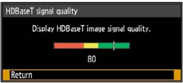
| High Indicated by the green portion. This is the recommended level. | |
| Middle Indicated by the yellow portion. The signal is fluctuating. Check the cable. | |
| Low | Indicated by the red portion. The signal cannot be used. Fix the cable connection or replace the cable. |

Do not coil or bundle cables.
Extron XTP

[System settings] > [Extron XTP]
Specify whether to connect to Extron XTP transmitters when connected via HDBaseT.
| Submenu Function |
| Off Do not connect to XTP devices. |
| On Connect to XTP devices. |
Serial communication

[System settings] > [Serial communication]
Select ports used for serial communication. Otherwise, you can refer to this setting to check setting values for the port selected for serial communication.
| Submenu Function | |
| Service port Use the service port (CONTROL). | |
| HDBaseT Use the HDBaseT port. | |
| Detail | |
| Option Function | |
| Baud rate Modulation rate, in bits per second. | |
| Data bits Number of bits of data. | |
| Parity Number of parity bits. | |
| Stop bit Length of mark representing the end of data bits. Select 1 or 2. | |
Power supply settings

[System settings] > [Power supply settings]
Specify how power is managed at startup, in standby, and when no signal is supplied.
| Power supply settings | |
| Standby power setting | Low-power |
| Power management mode | Light source off |
| Power management duration | 5 min. |
| Direct power on | On |
| Return | |
Standby power setting
Specify network function operating status in standby mode.
| Option Function | |
| Normal | All network functions are available when network functions are enabled, including the web screen and PJLink. |
| Low-power | All functions are disabled except for some wired LAN functions (such as operations over a network). |

- [Standby power setting] is set to [Normal] and cannot be changed when scheduling is enabled (P167).
- [Standby power setting] is set to [Normal] and cannot be changed when wireless LAN is enabled (P175).
- [Standby power setting] is set to [Normal] and cannot be changed when IPsec function is enabled (P205).
Power management mode
Specify to turn the light source off or enter standby if there is no input signal. This feature automatically turns off the light source or power after a certain period if the remote control or projector is not operated.
| Option Function | |
| Disabled Disable power management mode. | |
| Light source off Only turns the light source off. | |
| Standby Turns the projector off and puts it in standby. |

- Projection resumes when the same input signal is restored, when the remote control or projector is operated, or when user commands are sent to turn the projector on.
• After the projector enters standby, restoring projection requires the same steps as when turning the projector on normally. - When [Disabled] is selected, [Direct power on] is not available.
Power management duration
Specify how much time must pass before the light source goes off or the projector enters standby mode, depending on the [Power management mode] setting.
| Option Function | |
| 5 min. – 60 min. | After 30 seconds without an input signal when the projector is idle, the projector starts displaying a countdown of the selected time. |

- If conditions that would start countdown are met while you are blanking projection, blanking is canceled.
- Once countdown begins, audio output stops.
Direct power on
You can turn on the projector by connecting the power cable without pressing the POWER button.
| Option Function | |
| Off | The POWER button must be pressed to turn the projector on. |
| On You can turn on | the projector by connecting the power cable only. |

- Before enabling direct power on, be sure to set [Power management mode] to an option other than [Disabled]. When [Disabled] is selected, [Direct power on] is not available.
• After turning off the projector, wait at least 5 minutes before turning it on again. It may shorten the lamp life if you turn on the projector immediately after turning it off. - The projector is also equipped with a Direct Power Off feature. No damage is caused to the projector even if it is unplugged during projection to turn it off without pressing the POWER button. However, setting adjustments made immediately before unplugging the projector may not be stored.
Motion blur reduction

[System settings] > [Motion blur reduction]
Motion blur is blurring that occurs during video playback. Motion blur reduction can make this blurring less noticeable.
| Option Function | |
| Off Motion blur reduction is not performed. | |
| Weak | Reduce motion blur for fast-moving images. Note that images may be slightly darker, and flickering may occur. |
| Strong | Reduce motion blur for images moving faster than with [Weak]. Note that images may be darker, and flickering may occur. |

- If setting the projector to [Strong] or [Weak] produces distracting flickering, set it to [Off].
- [Motion blur reduction] is not available in [DICOM SIM] image mode. The menu is grayed out.
- Motion blur reduction is not available when [Lamp mode] is set to [Power saver 2].
Language

[System settings] > [Language]
Select the menu display language.
| Language | ||
| EnglishEnglish Russian Czech | Русский | Čeština |
| DeutschGerman Dutch Danish | Nederlands | Dansk |
| FrançaisFrench Finnish Arabic | Suomi | إنجليزی |
| ItalianoItalian Norwegian Chinese (Simplified) | Norsk | 中文简体 |
| EspañolSpanish Turkish Chinese (Traditional) | Türkçe | 中文繁體 |
| PortuguêsPortuguese Polish Korean | Polski | 한국어 |
| SvenskaSwedish Hungarian Japanese | Magyar | 日本語 |
Other settings

[System settings] > [Other settings]
Register a password, set a password, reset counters for lamp or air filter, schedule operation, and access other settings and information.
| Other settings | |
| Password settings | Off |
| Register password | |
| Date and time settings | |
| Schedule | |
| Gamma restore | Off |
| Lamp counter | |
| Air filter counter | |
| Power counter | 3H |
| Firmware | 00.00131 |
| Factory defaults | |
| Return | |
Password settings
Disables the projector unless the correct password is entered.
| Option Function |
| Off The projector can be used even if no password is entered. |
| On The projector cannot be used unless you enter your password. |
To Cancel the Password
| Cancellation on the Projector | Turn off the projector and unplug the power plug. Hold down the MENU button on the side control and connect the power plug. Make sure to keep holding down the MENU button until a beep sounds. When the projector beeps, the password is canceled. (The entered password is also reset.) |
| Cancellation on the Remote Control | To forcibly cancel the password from the remote control, in standby state press the MENU button 3 times, then press the POWER button. |

- You cannot set [On] unless you have completed [Register password].
Once you set a password, the password entry screen appears at power-on. Enter a 4 digit password.
Enter the password using the [▲/ [ ]▶[ ] / [▼] buttons or number buttons on the remote control.
If the password is valid, the projection starts. If you enter a wrong password three times, the power will be turned off. - The projector also goes off after three minutes of inactivity on the password input screen.
Register password
You can register a password for starting projection.
Enter a 4 digit password.
Enter the password using the pointer buttons [▲(1) / [ ] (2) / [ ] (3) / [ ] (4) or the number buttons on the remote control.
The 4-digit password is entered from the left to right digits. When the final digit is entered, the password is automatically registered.
Press the MENU button to abort the registration.
Date and time settings
Set time settings such as the current date and time, date/time display format, daylight saving time, and time zone.
| Submenu Function | |
| Date and time | Set the date and time. The date and time currently set are shown and updated each second.[12A4] The display is blank if the [Date and time] setting has not been set. |
| Submenu Function | |
| Date Enter the date. | |
| Time Enter the time. | |
| Enter Confirms your entered values. At this time [Date and time] starts operating. | |
| The date/time display format is set in [Date display format].Settings may be reset if the projector is left unplugged for an extended period. | |
| Date display format | Choose [Year/month/date], [Month/date/year], or [Date/month/year] as the date display format shown for the date and time, in schedules, and elsewhere. |
| Daylight saving time | Adjusts the time one hour ahead at the beginning of daylight saving time and one hour back at the end. The timing of daylight saving time must be set in advance. |
| Option Function | |
| Off Disable daylight saving time. | |
| On Enable daylight saving time. | |
| Edit Edit when daylight saving time starts and ends. Set the month, day, and time on the editing screen shown next for the starting and ending date/time. | |
| [44WIC] [On] in [Daylight saving time] is not available until the starting and ending timing are set. | |
| Region | Select a city in the time zone where the projector is installed.The time zone of the city selected in [Time zone] is shown. |
Submenu Function
| Date Enter the | date. |
| Time Enter the | time. |
| Enter | Confirms your entered values. At this time [Date and time] starts operating. |
| Option Function | |
| Off Disable daylight saving time. | |
| On Enable daylight saving time. | |
| Edit | Edit when daylight saving time starts and ends. Set the month, day, and time on the editing screen shown next for the starting and ending date/time. |
| Submenu Function | |
| SNTP | Select whether to sync the time on the projector using SNTP (Simple Network Time Protocol). |
| Submenu Function | |
| On (IPv4) Use SNTP over an IPv4 connection. | |
| On (IPv6) Use SNTP over an IPv6 connection. | |
| Off Disable SNTP. | |
| • [SNTP] is not available when [Network (wired/wireless)] is set to [Off/Off].• Use the web screen to set the IP address of the SNTP server. [SNTP] is not available unless the SNTP server IP address has been set. | |
Schedule
Some projector tasks can be automated by scheduling them. As the timing of scheduled tasks, choose from [Default], which is not during a certain period, or one of five special period times that you set up.
| Schedule | ||
| When a [Special period (1 to 5)] is specified, the[Default] schedule is suspended during that period. | ||
| Default | Off | |
| Special period 1 | Off | 2017/10/16 - 2017/10/27 |
| Special period 2 | Off | 2017/11/01 - 2017/11/10 |
| Special period 3 | Off | 2017/11/15 - 2017/11/24 |
| Special period 4 | Off | 2017/11/27 - 2017/12/08 |
| Special period 5 | Off | 2017/12/12 - 2017/12/22 |
| Return | ||

The [Period] setting of a special period cannot be set to overlap with another period.
| Option Function | |
| Default Set a general schedule that is not during a specific period. | |
| Special period 1 – 5 | Set up to five specific periods to schedule operation. |

• [On] is grayed out until you set the period in [Special period 1] to [Special period 5].
- [On] and [Off] are grayed out for periods in [Special period 1] to [Special period 5] that have already passed.
- Setting any schedule to [On] changes [Standby power setting] (P162) to [Normal].
- Tasks scheduled under the [Default] setting are not executed while special period schedules are in effect.
Detailed schedule setting
![Schedule When a [Special period (1 to 5)] is specified, the [Default] schedule is suspended during that period. Default ▶ Off Special period 1 On Special period 2 Edit Special period 3 Off 2017/11/15 - 2017/11/24 Special period 4 Off 2017/11/27 - 2017/12/08 Special period 5 Off 2017/12/12 - 2017/12/22 Return](/content/2026/05/965391/images/a0c8b09758d58c9e162436301158e661a47019e4547a6998d2eeaf051964cf6e.jpg)
| Option Function | |
| Off Disable the schedule. | |
| On Enable the schedule. | |
| Edit | Edit the schedule. ■ Default |
| Detailed schedule setting [Default] | |
| Day of week ▲ Monday ▶ Edit schedule 08: 00 POWER ON 08: 00 INPUT HDMI 10: 00 INPUT DisplayPort 12: 00 INPUT D_PC 14: 30 INPUT DisplayPort 15: 00 INPUT HDMI 16: 15 INPUT D_PC 17: 30 POWER OFF | |
| Reset Copy schedule to different day Return | |
Option Function
![Special period Detailed schedule setting [Special period 1] Period 2017 / 10 / 16 - 2017 / 10 / 27 Day of week Wednesday Edit schedule 08 : 00 POWER ON 08 : 00 Nepal HDMI 10 : 00 Nepal DisplayPort 12 : 00 Nepal D_PC 14 : 00 Nepal HDMI 15 : 30 Nepal DisplayPort 17 : 00 Nepal HDMI 17 : 30 Nepal OFF Reset Copy schedule to different day Return](/content/2026/05/965391/images/4d5d21dbbba38b990ea98136c7e3fdc2ef2c3b2c567ecb834c10dd43954be2a8.jpg)
Select a day in [Day of week], and select the times, operations, and parameters.
Edit
| Submenu Function | |
| Period | Edit the period (start and end dates) for scheduled operation. Note that no [Period] setting is used for the [Default] schedule. |
| Day of week Change the day of the week to edit. | |
| Edit schedule | Edit the tasks scheduled for your selected [Day of week]. You can set or remove listed times, operations, and parameters (POWER ON/OFF, INPUT). |
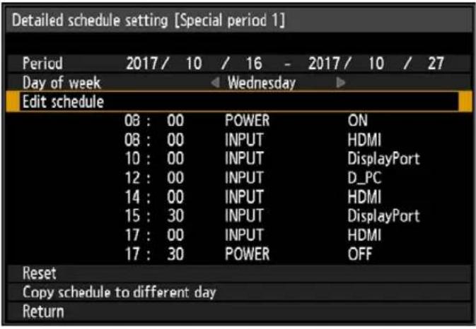 | |
Option Function
| Edit | Submenu Function | |
| Reset | Clears setting details for the selected schedule. Setting details for [Period] and day of the week are reset. | |
| Copy schedule to different day | Copy the tasks scheduled for your selected [Day of week] to another day in the schedule copying menu. | |
| Copy schedule to different day [Special period 1]Specify copy destination for following schedule.Copy source Wednesday08:00 POWER ON08:00 INPUT HDMI10:00 INPUT DisplayPort12:00 INPUT D_PC14:00 INPUT HDMI15:30 INPUT DisplayPort17:00 INPUT HDMI17:30 POWER OFFMonday Tuesday Wednesday ThursdayFriday Saturday Sunday Cancel allEnterReturn | ||
Gamma restore
Restore the original gamma if, after the projector has been used for some time, you notice that tone curves have changed, or if neutral colors have become tinted. Gamma restore can only be used when the lamp has been on for approximately 30 minutes or longer.
| Submenu Function | |
| Off Returns to the factory default without performing Gamma restore. | |
| Adjust Restore the original gamma and apply the result. |

- If Gamma restore is performed, the tone characteristics and achromatic color will be restored as close as possible to the condition when the projector was purchased (factory default), however it is not possible to restore it completely to the original condition.
- If Gamma restore is performed, the adjustment screen will be projected for approximately 3 minutes.
- To stop Gamma restore, press the POWER or EXIT button. Cancellation will return the setting to [Off].
Lamp counter
You can reset the lamp counter that indicates the time for lamp replacement.
For details on lamp counter display, see "Replacing the Lamp" (P210).

- Do not reset the lamp counter except when you have replaced the lamp. Otherwise, the lamp counter cannot indicate the correct timing for replacing the lamp.
- Lamps are more likely to rupture once the lamp replacement message has been displayed (P210). Replace the lamp with a new one as soon as possible.
- The lamp counter provides an estimate of the time remaining until the lamp must be replaced. This value is based on the hours in use and the present load on the lamp.
- The number of hours indicated is equivalent to use under these conditions: [Lamp mode] (P141) set to [Full power].
Air filter counter
Shows a counter to remind you when to replace the air filter.
Also shows a counter reset screen.

• After air filter replacement, reset the air filter counter.
- For details on replacing the air filter, see P207 – P209.
Power counter
Indicates the total time that the projector has been connected to a power supply.

This value is not reset even if [Factory defaults] is executed.
Firmware
Update the projector firmware.
Check the version indicated before updating the firmware.
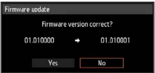
Update the projector firmware as follows.
-
Download updated firmware from the Canon website and store it at the root directory on a USB flash drive.
-
Insert the USB flash drive in the USB port.
-
Follow the instructions shown to complete the update process.

- Firmware versions shown here are for illustration only and differ from actual versions.
- In some cases, it may not be possible to download updates. For details, contact the Canon Customer Support Center.
- Firmware updating takes a few minutes. During the update, the LED indicator will flash in red. Do not turn off the projector while the LED is flashing. After the update, the projector will automatically turn itself off and enter standby mode.
Factory defaults
You can reset the menu item settings and restore the system settings to the factory defaults.
| Option Function | |
| OK Settings are reset to default. | |
| Cancel Settings are not reset to default. |
Network settings
Settings described in this section apply to wired and wireless network connections, setting a network password, and other aspects of networked projection.
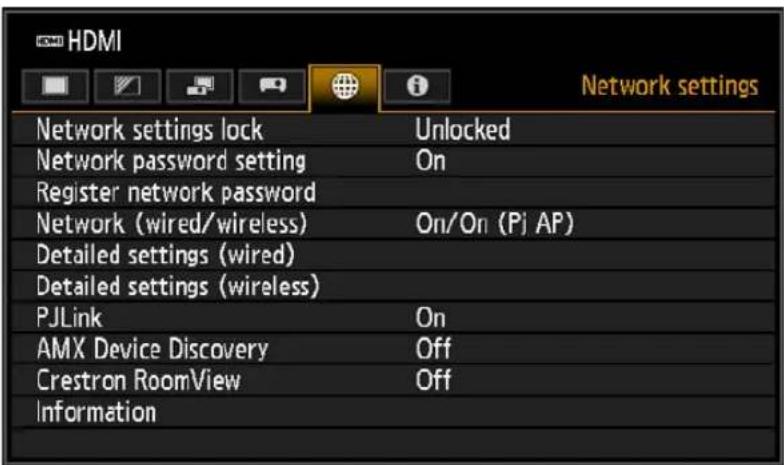
Menu screen when the input signal is HDMI
| Menu Function | Details | |
| Network settings lock | Lock or unlock network settings, depending on whether you wish to prevent changes. | P174 |
| Network password setting | Activate or deactivate password protection for network settings. | P174 |
| Register network password | Set a network password. P174 | |
| Network (wired/ wireless) | Enable or disable wired or wireless network connectivity and the mode of operation. | P175 |
| Detailed settings (wired) | Display and set advanced settings for wired connections. | P176 |
| Detailed settings (wireless) | Display and set advanced settings for wireless connections. | P180 |
| PJLink* Enable or disable | PJLink. P185 | |
| AMX Device Discovery* | Enable or disable AMX Device Discovery. P186 | |
| Crestron RoomView* | Enable or disable Crestron RoomView. P186 | |
| Information Display network information. P187 | ||
Menus that are not available are grayed out or hidden.
* Only available for wired connections.
Network settings lock

[Network settings] > [Network settings lock]
You can lock/unlock the network settings so that they cannot be changed.
| Option Function | |
| Unlock | Cancels the lock and allows other network settings to be changed. The password must be entered in order to cancel the lock. Use the [▲/ [▼/ [ ]buttons or number buttons on the remote control to enter the 4-digit network password. |
| Lock Lock the settings. | |

- Forcibly canceling the network lock
Press these buttons in the following order to cancel the lock: [OK] [ ] OK] [ ]
[OK]. This operation resets the network password to [▲] [▲] [▲1] [▲] [1] [1]).
- Setting [Network password setting] to [Off] leaves network settings unlocked.

Network password setting

[Network settings] > [Network password setting]
You can set whether or not a password is required in order to change the projector network settings.
| Option Function | |
| Off A network password is not used. | |
| On A network password is used. |
Register network password

[Network settings] > [Register network password]
Use the [▲/ [ ]▶[ ] / ▼] buttons or number buttons on the remote control to enter the projector network password.
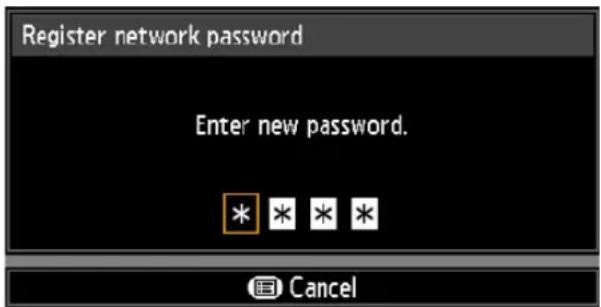
Network (wired/wireless)

[Network settings] > [Network (wired/wireless)]
Enable or disable wired or wireless network connectivity and the mode of operation. Specifying [Off] can save energy.
| Option Function | |
| Off/Off Disable the network function. | |
| On/Off Enable only wired networking. | |
| On/On (Pj AP) Enable both wired and wireless (PJ AP mode) networking. | |
| Off/On (Pj AP) Enable only wireless (PJ AP mode) networking. | |
| Off/On (Infra) Enable only wireless (infrastructure mode) networking. | |

Notes When Connected Wirelessly
- A message is displayed at the initial startup in PJ AP mode (P82) requesting that you check security key settings.
- The [Network (wired/wireless)] setting cannot be changed when the projector is set to [Primary] or [Secondary] in PC-free multi projection mode.
Detailed settings (wired)

[Network settings] > [Detailed settings (wired)]
Display and manually change the wired IP address, gateway address, and other settings. Available only when wired networking is [On].
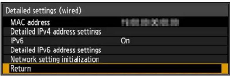
| Menu Function | ||
| MAC address Wired | MAC address of the projector. | |
| Detailed IPv4 address settings | Configure details of the projector's wired LAN (IPv4) function. | |
| Detailed IPv4 address settings (wired)IP address 192. 168. 254. 254Subnet mask 255. 255. 255. 0Gateway address 0. 0. 0. 0DHCP OffTCP/IP settingsReturn | ||
| Submenu Function | ||
| IP address IP address of the wired LAN (IPv4). | ||
| Subnet mask Subnet mask of the wired LAN (IPv4). | ||
| Gateway address Gateway address of the wired LAN (IPv4). | ||
| DHCP | Option Function | |
| OffDisables the DHCP function. TCP/IP settings can be configured manually. | ||
| OnEnables the DHCP function Searches the DHCP server. It will no longer be possible to enter TCP/IP manual settings (IP address, subnet mask, and gateway address), because the IP address is acquired from the DHCP server. | ||
| Detailed IPv4 address settings | Submenu Function | |
| TCP/IP settings | Change or specify the IP address, subnet mask, and gateway address used for connections.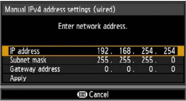 | |
 This menu is not available (grayed out) when [DHCP] (P176) is [On].If an invalid value is entered, “Invalid entry.” is displayed. In this case, enter a valid value.When [Network (wired/wireless)] is set to [On/On (Pj AP)], “Cannot set identical segment IP” is displayed if you specify the same subnetwork as in PJ AP mode. Enter a different subnetwork, or change [Network (wired/wireless)] to [On/Off] before entering the wired IP address again. This menu is not available (grayed out) when [DHCP] (P176) is [On].If an invalid value is entered, “Invalid entry.” is displayed. In this case, enter a valid value.When [Network (wired/wireless)] is set to [On/On (Pj AP)], “Cannot set identical segment IP” is displayed if you specify the same subnetwork as in PJ AP mode. Enter a different subnetwork, or change [Network (wired/wireless)] to [On/Off] before entering the wired IP address again. | ||
| IPv6 | Option Function | |
| Off Disables the projector's wired LAN (IPv6) function. | ||
| On | Enables the projector's wired LAN (IPv6) function.[Detailed IPv6 address settings] is now available. | |
| Menu Function | Configure details of the projector's wired LAN (IPv6) function. | |
| Detailed IPv6 address settings | 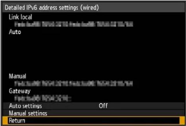 | |
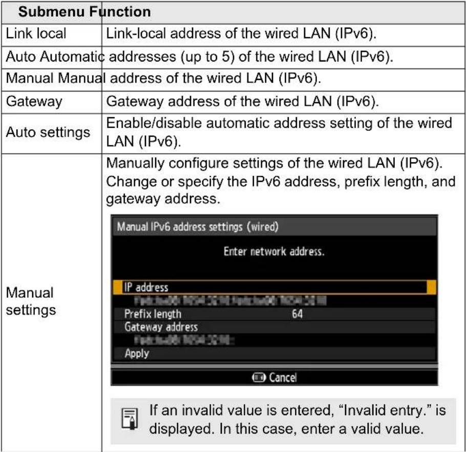 | ||
| Menu Function | ||
| Network setting initialization | The following network settings are initialized.Settings configured from the projector menuNetwork settings lock (P174)Network password setting (P174)Register network password (P174)Network (wired/wireless) (P175)Detailed settings (wired) (P176)- Detailed IPv4 address settings (P176)- DHCP (wired LAN (IPv4)) (P176)- TCP/IP settings (P177)- IP address (wired LAN (IPv4)) (P176)- Subnet mask (wired LAN (IPv4)) (P176)- Gateway address (wired LAN (IPv4)) (P176)- IPv6 (P177)- Detailed IPv6 address settings (P178)- Auto settings (P178)- Manual settings (P178)- IP address (wired LAN (IPv6)) (P178)- Prefix length (P178)- Gateway address (wired LAN (IPv6)) (P178)PC-free multi projectionDestination projector setting [1]IP address – [9]IP addressPJLink (P185)AMX Device Discovery settings (P186)Crestron RoomView settings (P186)Settings configured from the web screen[Password] (P189)[Wired] (P195)- IPv4- DHCP (P196)- IP address (P196)- Subnet mask (P196)- Default gateway (P196)- IPv6- IPv6 (P196)- Autoconfiguration (P196)- IP address (P196)- Prefix length (P196)- Default gateway (P196)[NMPJ Passw ord] (P199)[Mail] (P200)[SNMP] (P202)[Projector info.] (P203)[PJLink] (P203)[IPsec] (P205) | |
Detailed settings (wireless)

[Network settings] > [Detailed settings (wireless)]
Display and manually change the wireless IP address, gateway address, and other settings. Available only when wireless networking is [On].
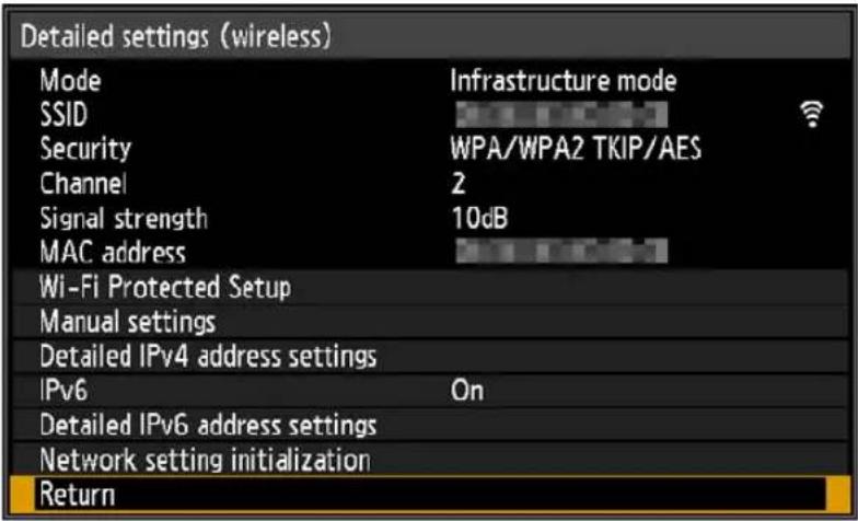
| Menu Function | |
| Mode Shows the wireless connection mode (P82). | |
| SSID Shows the access point SSID. | |
| Security Shows the security setting. | |
| Channel Shows the channel used for the connection. | |
| Signal strength Shows actual signal strength, as measured. | |
| MAC address Wireless MAC address of the projector. | |
| Wi-Fi Protected Setup | Select the method of connection in infrastructure mode. |
| Submenu Function | |
| PBC Connect in PBC (push-button) mode.Following the instructions shown, press the button on the wireless base station (access point), and, within 2 minutes, select [OK] on the screen. | |
| PIN Connect in PIN mode.Following the instructions shown, enter the displayed 8-digit PIN code on the wireless base station (access point), and, within 10 minutes, select [OK] on the screen. | |
| Menu Function | Manually specify the projector's wireless settings. |
| Manual settings | 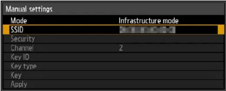 |
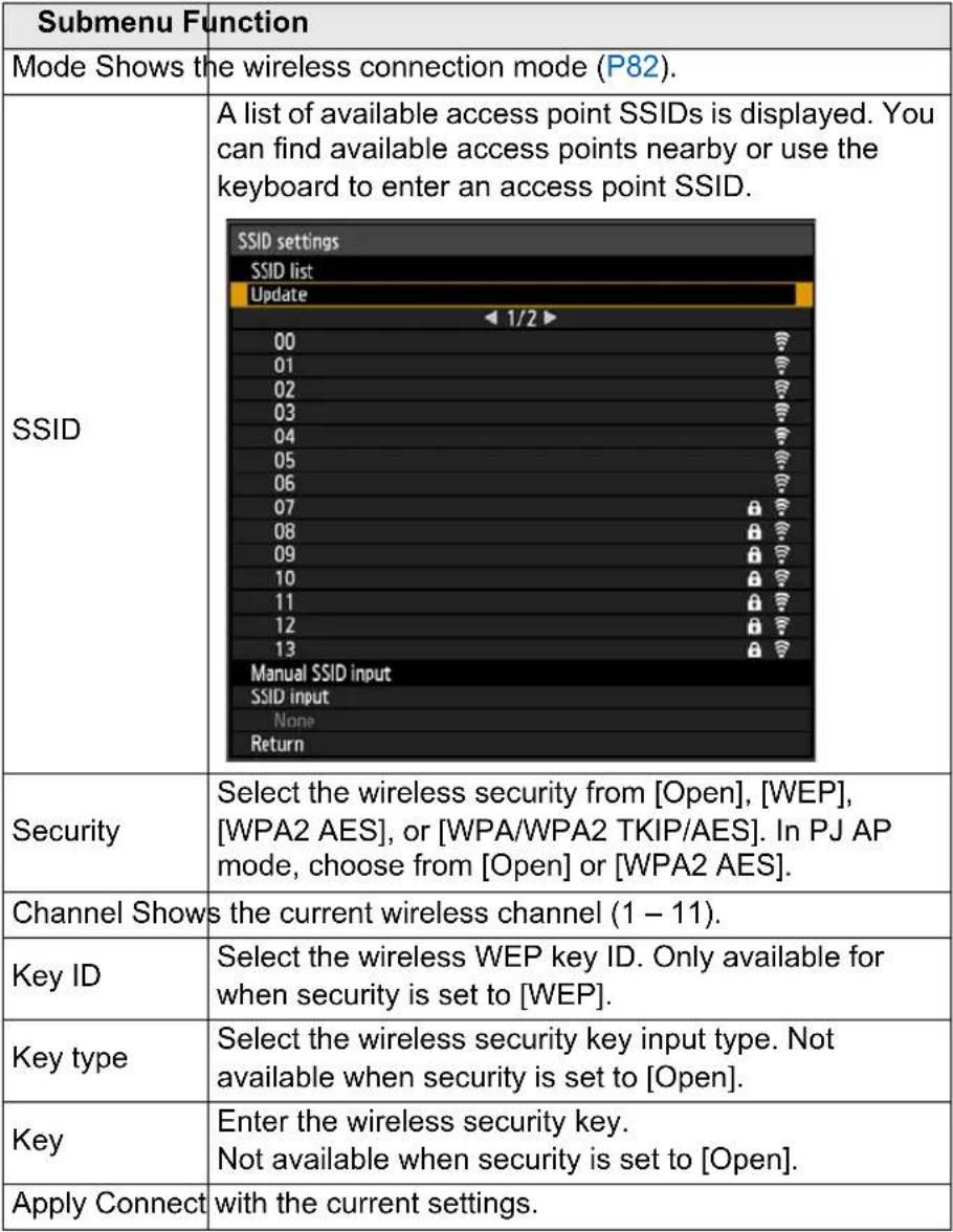 | |
| Menu Function | ||
| Detailed IPv4 address settings | Configure details of the projector's wireless LAN (IPv4) function. | |
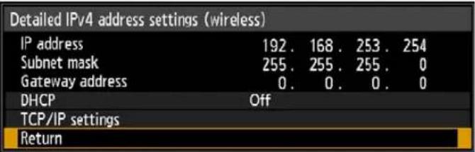 | ||
| Submenu Function | ||
| IP address IP address of the projector's wireless LAN (IPv4). | ||
| Subnet mask | Subnet mask of the projector's wireless LAN (IPv4). | |
| Gateway address | Gateway address of the projector's wireless LAN (IPv4). | |
| DHCP | Enable or disable wireless DHCP on the projector. | |
| Option Function | ||
| Off | ||
| On | ||
| TCP/IP settings | Configure the projector's wireless TCP/IP settings. | |
| This menu is not available (grayed out) when [DHCP] is [On].If an invalid value is entered, "Invalid entry." is displayed. In this case, enter a valid value. | ||
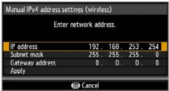 | ||
| Menu Function | ||
| IPv6 | Option Function | |
| Off Disables the projector's wireless LAN (IPv6) function. | ||
| On | Enables the projector's wireless LAN (IPv6) function. [Detailed IPv6 address settings] is now available. | |
| [77c4] IPv6 connectivity is not available in PJ AP mode (P175). The [IPv6] and [Detailed IPv6 address settings] menus are grayed out. | ||
| Detailed IPv6 address settings | Configure details of the projector's wireless LAN (IPv6) function. | |
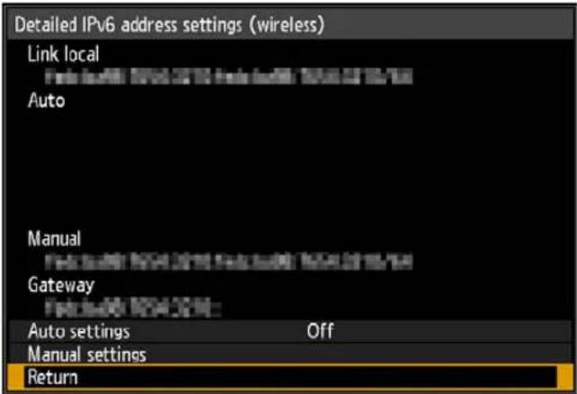 | ||
| Submenu Function | ||
| Link local | Link-local address of the wireless LAN (IPv6). | |
| Auto | Automatic addresses (up to 5) of the wireless LAN (IPv6). | |
| Manual Manual address of the wireless LAN (IPv6). | ||
| Gateway | Gateway address of the wireless LAN (IPv6). | |
| Auto settings | Enable/disable automatic address setting of the wireless LAN (IPv6). | |
| Manual settings | Manually configure settings of the wireless LAN (IPv6). Change or specify the IPv6 address, prefix length, and gateway address. | |
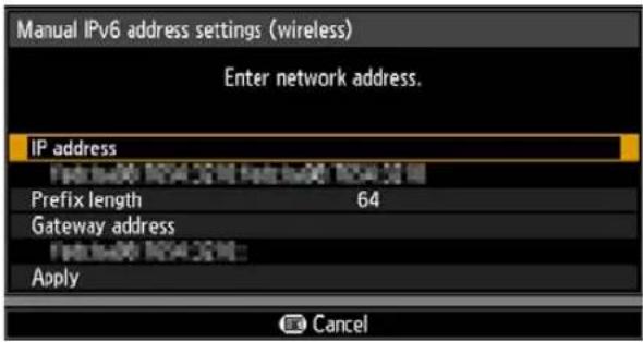 If an invalid value is entered, “Invalid entry.” is displayed. In this case, enter a valid value. If an invalid value is entered, “Invalid entry.” is displayed. In this case, enter a valid value. | ||
| Menu Function | The following network settings are initialized.Settings configured from the projector menuNetwork settings lock (P174)Network password setting (P174)Register network password (P174)Network (wired/wireless) (P175)Detailed settings (wireless) (P180)- Detailed IPv4 address settings (P182)- DHCP (wireless LAN (IPv4)) (P182)- TCP/IP settings (P182)- IP address (wireless LAN (IPv4)) (P182)- Subnet mask (wireless LAN (IPv4)) (P182)- Gateway address (wireless LAN (IPv4)) (P182)- IPv6 (P183)- Detailed IPv6 address settings (P183)- Auto settings (P183)- Manual settings (P183)- IP address (wireless LAN (IPv6)) (P183)- Prefix length (P183)- Gateway address (wireless LAN (IPv6)) (P183)Settings configured from the web screen[Password] (P189)[Wireless] (P197)- IPv4- DHCP (P197)- IP address (P197)- Subnet mask (P197)- Default gateway ( P197)- IPv6- IPv6 (P198)- Autoconfiguration (P198)- IP address (P198)- Prefix length (P198)- Default gateway (P198)[NMPJ Passw ord] (P199)[Mail] (P200)[Projector info.] (P203)[IPsec] (P205) |
| Network setting initialization |
PJLink

[Network settings] > [PJLink]
You can enable or disable the PJLink network function of the projector.
When the function is turned on, control is possible via the network using commands that meet PJLink standards.
| Option Function | |
| Off Disables the PJLink function. | |
| On Enables the PJLink function. | |

- The projector conforms to Class 2 as defined in PJLink standards established by the Japan Business Machine and Information System Industries Association (JBMIA). This projector supports all commands that are defined by PJLink Class 2, and PJLink compatibility has been verified.
- The port number for PJLink command transmission is 4352 (TCP).
- The port number for PJLink device searching is 4352 (UDP).
- For details on using PJLink, see "Setting PJLink [PJLink]" (P203).
Sources and corresponding input terminals
| Input source number Input signal name | |
| 11 Analog PC-1 | |
| 12 Analog PC-2 | |
| 13 Component | |
| 31 Digital PC | |
| 32 HDMI | |
| 33 DisplayPort | |
| 41 USB | |
| 51 LAN | |
| 52 HDBaseT | |
What is PJLink?
It allows centralized control of projectors and operation from a controller for all projectors regardless of manufacturer.
The objective is for JBMIA to improve convenience for users and expand the use of projectors through early systemization for network monitoring and control of projectors, which will become the mainstream in the future.
Class 1: Standardization of control and monitoring specifications for basic projector functions
Class 2: Standardizes commands added to Class 1, device searching, state notification, and IPv6 support.
For PJLink specifications, visit the Japan Business Machine and Information System Industries Association website.
PJLink website: http://pjlink.jbmia.or.jp/english/
AMX Device Discovery

[Network settings] > [AMX Device Discovery]
This setting enables other equipment compatible with AMX Device Discovery to detect the projector over a network. For networks without AMX Device Discovery, select [Off].
| Option Function | |
| Off Disables AMX Device | Discovery. |
| On | Enables AMX Device Discovery. The projector will periodically send out AMX beacon packets over the network. |

- For details on AMX Device Discovery, visit the AMX website. http://www.amx.com
Crestron RoomView

[Network settings] > [Crestron RoomView]
Crestron RoomView enables centralized management of multiple projectors over a network. Networked projectors can be remotely controlled to troubleshoot issues, check the useful life of lamps, or turn the projectors on or off. Specify whether to use Crestron RoomView.
| Option Function | |
| Off Disable Crestron RoomView. | |
| On | Enables Crestron RoomView. A port for RoomView will be opened, and the projector will respond to CIP packets.Communication is possible via the RoomView Express/Server application or via Crestron Controller (P204). |

- For details on Crestron RoomView, visit the Crestron® website. http://www.crestron.com
Information

[Network settings] > [Information]
Shows network information.
| Menu Function | |||
| E-mail sender address | Sender e-mail address for sending error messages (P200). | ||
| E-mail recipient address | [Already set] or [Not set] is shown, indicating whether a recipient e-mail address has been set for error messages (P200). | ||
| Detailed information (wired) | IPv4 IP address of the wired LAN (IPv4). | ||
| IPv6 | Link local Link-local IP address of the wired LAN (IPv6). | ||
| Auto Automatic IP address of the wired LAN (IPv6). | |||
| Manual Manual IP address of the wired LAN (IPv6). | |||
| Detailed information (wireless) | IPv4 IP address of the wireless LAN (IPv4). | ||
| IPv6 | Link local Link-local IP address of the wireless LAN (IPv6). | ||
| Auto Automatic IP address of the wireless LAN (IPv6). | |||
| Manual Manual IP address of the wireless LAN (IPv6). | |||

- [Detailed information (wired)] menu information is displayed when [Network (wired/wireless)] is set to [On / *] .
- [Detailed information (wireless)] menu information is displayed when [Network (wired/ wireless)] is set to [*/On].
Checking Projector Information
You can check information about the signal types of the images projected and other information.
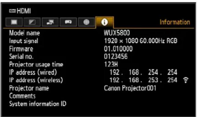
| Menu Function | |
| Model name Shows the model name. | |
| Input signal | Details of the input signal currently selectedInformation such as the type, resolution, frequency, and color format of the signal is displayed. |
| Firmware Current firmware version | |
| Serial no. Serial number unique to this projector | |
| Projector usage time Shows the total time the projector has been on. | |
| IP address (wired)* IP address (IPv4) for wired connections. | |
| IP address (wireless)* IP address (IPv4) for wireless connections. | |
| Projector name* Name which identifies this projector on the network | |
| Comments* | Comments such as the location in which the projector is installed are displayed (P203). |
| System information ID System information. Normally this is not displayed. | |
* No value is displayed when [Network (wired/wireless)] is set to [Off/Off]. Some values may not be displayed, depending on [Network (wired/wireless)] settings. (○displayed, —: not displayed)
| Network(wired/wireless) | Off/Off On/Off | On/On(Pj AP) | Off/On(Pj AP) | Off/On(Infra) | |
| IP address (wired) — | ○ | ○ — | — | ||
| IP address (wireless) | — | — | ○ | ○ | ○ |
| Projector name | — | ○ | ○ | ○ | ○ |
| Comments | — | ○ | ○ | ○ | ○ |
Projector Web Screen Menu
This section describes the projector's web screen menu.
Setting a Password [Password]
From [Password] in the settings screen, you can set a user name and password for web screen login. For the setting procedure, see "Network Setting" (P89).
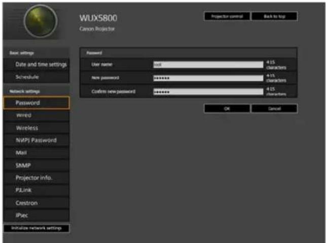
| Item Explanation | Factory default setting | |
| User name When logging | into the web screen,enter the user name in 1-byte alphanumeric characters and symbols (4 – 15 characters). | root |
| New password When logging | ing into the web screen,enter the password in 1-byte alphanumeric characters and symbols (4 – 15 characters). | system |
| Confirm new password For | confirmation, enter the same password that you entered in [New password]. | system |
![CANON REALiS WUX6700 - Setting a Password [Password] - 2](/content/2026/05/965391/images/d821bf6bdc0aa7d61b08ef22baab2006444db1e5a52d66e5e176ce53c56af209.jpg)
We recommend changing the default password.
Setting the Date and Time [Date and time settings]
From [Date and time settings] in the settings screen, you can set time settings such as the current date and time, date/time display format, time zone, and daylight saving time. For the setting procedure, see "Network Setting" (P89).
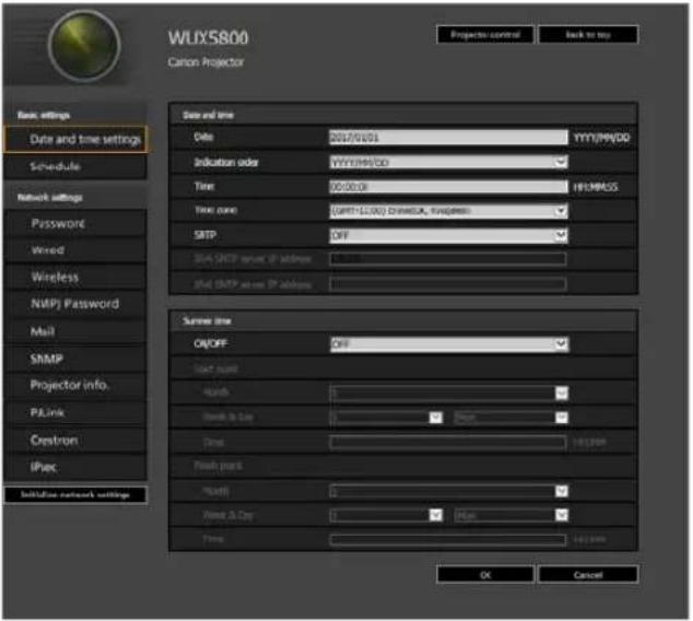
| Item Explanation Factory default setting | |||
| Date and time | Date Enter the date in 1-byte numbers. 2018/01/01 | ||
| Indication order | Choose [YYYY/MM/DD], [MM/DD/YYYY], or [DD/MM/YYYY] as the date display format. | YYYY/MM/DD | |
| Time Enter the time in 1-byte numbers, in the range 00:00:00 to 23:59:59. | 00:00:00 | ||
| Time zone Select a city in your time zone. (GMT) Dublin, Lisbon, London | |||
| SNTP Select whether to turn the SNTP(Simple Network Time Protocol) function on or off.Choosing [ON (IPv4)] will prevent you from configuring the following settings.[Date][Time][IPv6 SNTP server IP address] Choosing [ON (IPv6)] will prevent you from configuring the following settings.[Date][Time][IPv4 SNTP server IP address] | OFF | ||
| IPv4 SNTP server IP address | Enter the IPv4 SNTP server IP address in 1-byte numbers. | 0.0.0.0 | |
| IPv6 SNTP server IP address | Enter the IPv6 SNTP server IP address in 1-byte numbers. | ||
| Item Explanation | Factory default setting | ||
| Summer time | ON / OFF Select whether to turn the summer time function on or off (Time adjustment one hour ahead at the beginning of daylight saving time and one hour back at the end). Choosing [OFF] will prevent you from configuring the following settings. [Start point Month] [Start point Week] [Start point Day] [Start point Time] [Finish point Month] [Finish point Week] [Finish point Day] [Finish point Time] | OFF | |
| Start point Month | Select the month when daylight saving time begins. | 1 | |
| Start point Week | Select the week when daylight saving time beings. | 1 | |
| Start point Day | Select the day when daylight saving time begins. | Mon | |
| Start point Time | Enter the starting time for daylight saving time in 1-byte numbers, in the range 00:00 to 23:59. | 00:00 | |
| Finish point Month | Select the month when daylight saving time ends. | 1 | |
| Finish point Week | Select the week when daylight saving time ends. | 1 | |
| Finish point Day | Select the day when daylight saving time ends. | Mon | |
| Finish point Time | Enter the ending time for daylight saving time in 1-byte numbers, in the range 00:00 to 23:59. | 00:00 | |
Setting a Scheduling [Schedule]
From [Schedule] in the settings screen, you can automate some projector tasks by scheduling them. As the timing of scheduled operation, choose from [Usually], which is not during a certain period, or one of five special period times (Period.1 – Period.5) that you set up. For the setting procedure, see “Network Setting” (P89).
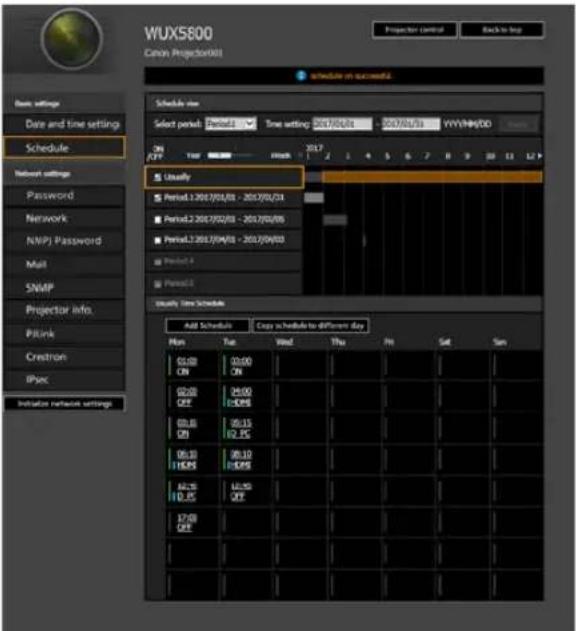
| Item Explanation | Factory default setting | ||
| Schedule view | Select period | Select a specific period to configure. Period.1 | |
| Time setting In the left box, enter the starting date of the specific period you are scheduling, and in the right box, enter the ending date, using 1-byte numbers.Dates of periods cannot be set to overlap. | 2018/01/01 | ||
| Usually Shows the usual schedule, which can be turned on or off by selecting the check boxes. | Cleared (OFF) | ||
| Period.1 Shows the timing of the scheduled period 1. Can be turned on or off by selecting the check box. | Cleared (OFF) | ||
| Period.2 Shows the timing of the scheduled period 2. Can be turned on or off by selecting the check box. | Cleared (OFF) | ||
| Period.3 Shows the timing of the scheduled period 3. Can be turned on or off by selecting the check box. | Cleared (OFF) | ||
| Period.4 Shows the timing of the scheduled period 4. Can be turned on or off by selecting the check box. | Cleared (OFF) | ||
| Schedule view | Period.5 Shows | s the timing of the scheduled period 5. Can be turned on or off by selecting the check box. | Cleared (OFF) |
| Time Schedule Shows times and days of the week of the usual schedule or period schedule selected in [Schedule view]. Green vertical line: projector on; gray vertical line: projector off; blue vertical line: switch input signals. Up to 8 schedules can be set per day. | — | ||
Clicking an item in [Time Schedule] displays the [Edit schedule] screen, enabling you to edit the schedule of the selected day or time.
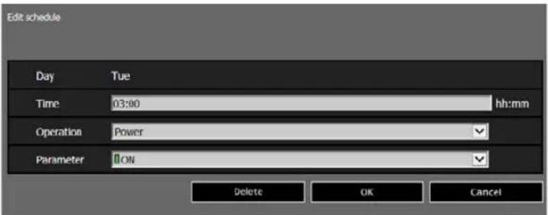
| Item Explanation | Factory default setting | ||
| Edit schedule | Day Shows the day of the week for the selected schedule. | — | |
| Time Enter the automatic execution time in 1-byte numbers, in the range 00:00 to 23:59. | |||
| Operation As the operation for automatic execution, choose [Power] or [Input]. | Power | ||
| Parameter As parameters for automatic execution, choose from the following options.When [Operation] is set to [Power]: [ON] / [OFF]When [Operation] is set to [Input]: [HDMI] / [DisplayPort] / [D_PC] / [A_PC1] / [A_PC2] / [COMP] / [HDBaseT] / [LAN] / [USB] | ON | ||
Projector Web Screen Menu
Clicking [Add schedule] in [Time Schedule] displays the [Add schedule] screen, enabling you to add a new schedule to the selected usual schedule or period schedule.
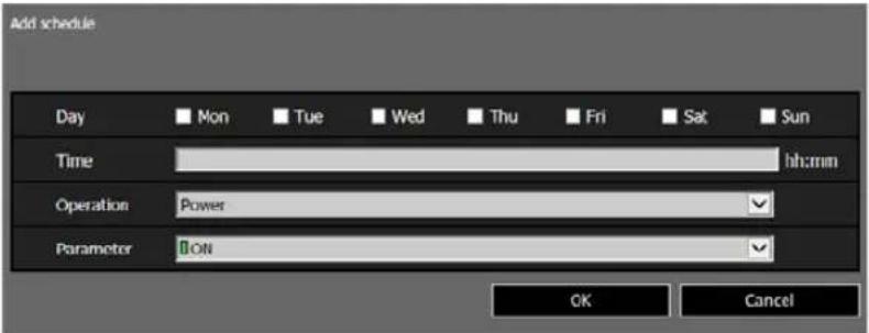
| Item Explanation | Factory default setting | ||
| Add schedule | Day Select a | day of the week for automatic execution. Multiple days can be selected. | Cleared |
| Time Enter the | automatic execution time in 1-byte numbers, in the range 00:00 to 23:59. | ||
| Operation As | the operation for automatic execution, choose [Power] or [Input]. | Power | |
| Parameter As | parameters for automatic execution, choose from the following options.When [Operation] is set to [Power]: [ON] / [OFF]When [Operation] is set to [Input]: [D_PC] / [A_PC1] / [A_PC2] / [COMP] / [HDMI] / [HDBaseT] / [DisplayPort] / [USB] / [LAN] | ON | |
Projector Web Screen Menu
Clicking [Copy schedule to different day] in [Time Schedule] displays the [Schedule copy] screen, enabling you to copy a schedule to any day for the selected usual schedule or period schedule.
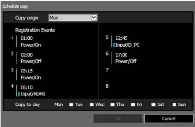
| Item Explanation | Factory default setting | ||
| Schedule copy | Copy origin S | Select the day to copy from. Mon | |
| Registration Events | Shows schedule details on the selected day. | ||
| Copy to day S | Select the day to copy to. Multiple days can be selected. | Cleared | |
Basic Wired Network Settings [Wired]
From [Wired] on the settings screen, you can complete basic network information for wired connections. For the setting procedure, see "Network Setting" (P89).
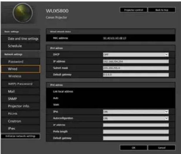
| Item Explanation | Factory default setting | ||
| MAC address Shows the | projector's wired MAC address. | The projector's wired MAC address | |
| IPv4 address | DHCP Select | whether to turn the DHCP function on or off for wired LAN (IPv4). The following settings cannot be configured manually when this setting is [ON], because the IP address is acquired from the DHCP server.[IP address][Subnet mask][Default gateway] | OFF |
| IP address Enter the projector's wired LAN (IPv4) IP address in 1-byte numbers. | 192.168.254.254 | ||
| Subnet mask | Enter the wired LAN (IPv4) subnet mask in 1-byte numbers. | 255.255.255.0 | |
| Default gateway | Enter the wired LAN (IPv4) default gateway address in 1-byte numbers. | 0.0.0.0 | |
| IPv6 address | IPv6 Specify on or off for the IPv6 function of the wired LAN (IPv6). Choosing [OFF] will prevent you from configuring the following settings.[Autoconfiguration][IP address][Prefix length][Default gateway] | OFF | |
| Autoconfiguration | Select on or off for the auto setting function of the wired LAN (IPv6). Choosing [ON] will prevent you from configuring the following settings.[IP address][Prefix length][Default gateway] | ON | |
| IP address Enter the wired LAN (IPv6) address in 1-byte numbers or letters between A and F. | |||
| Prefix length Enter the wired LAN (IPv6) prefix length in 1-byte numbers. | |||
| Default gateway | Enter the wired LAN (IPv6) default gateway address in 1-byte numbers or letters between A and F. | ||
![CANON REALiS WUX6700 - Basic Wired Network Settings [Wired] - 2](/content/2026/05/965391/images/a5462febe2fd092f7a63d4b5d6605be6661a53243c23cff02560334bfcff08dd.jpg)
If settings related to TCP/IP were changed, it is necessary to disconnect and reconnect to the network.
If the network subnet mask was changed, select [Subnet mask] in the above screen and set the new subnet mask.
Basic Wireless Network Settings [Wireless]
From [Wireless] on the settings screen, you can complete basic network information for wireless connections. For the setting procedure, see "Network Setting" (P89).
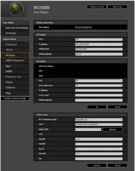
| Item Explanation | Factory default setting | ||
| MAC address Shows the projector's wireless MAC address. | The projector's wireless MAC address | ||
| IPv4 address | DHCP Select | whether to turn the DHCP function on or off for wireless LAN (IPv4). The following settings cannot be configured manually when this setting is [ON], because the IP address is acquired from the DHCP server.[IP address][Subnet mask][Default gateway] | OFF |
| IP address Enter the projector's wireless LAN (IPv4) IP address in 1-byte numbers. | 192.168.253.254 | ||
| Subnet mask | Enter the wireless LAN (IPv4) subnet mask in 1-byte numbers. | 255.255.255.0 | |
| Default gateway | Enter the wireless LAN (IPv4) default gateway address in 1-byte numbers. | 0.0.0.0 | |
| Item | Explanation | Factory default setting | |
| IPv6 address | IPv6 Specify on or off for the wireless LAN (IPv6) function.Choosing [OFF] will prevent you from configuring the following settings.[Autoconfiguration][IP address][Prefix length][Default gateway] | OFF | |
| Autoconfiguration | Select on or off for the auto setting function of the wireless LAN (IPv6). Choosing [ON] will prevent you from configuring the following settings.[IP address][Prefix length][Default gateway] | ON | |
| IP address Enter the wireless LAN (IPv6) IP address in 1-byte numbers or letters between A and F. | |||
| Prefix length Enter the wireless LAN (IPv6) prefix length in 1-byte numbers. | |||
| Default gateway | Enter the wireless LAN (IPv6) default gateway address in 1-byte numbers or letters between A and F. | ||
| Wireless setting | Wi-Fi Protected Setup | Select a method of establishing a wireless connection. Not available in PJ AP wireless LAN mode. | None (Manual) |
| Mode Display | or select the wireless connection mode. Not available in PJ AP wireless LAN mode. | infrastructure mode (select) | |
| Select SSID S | Select the wireless access point's SSID. Not available in PJ AP wireless LAN mode. | ||
| SSID Display | or select the wireless access point's SSID. Partial SSID editing is supported in PJ AP wireless LAN mode. | ||
| Security Display or select the wireless security setting value. | Open | ||
| Channel Display or select the wireless channel number. Not available when the wireless LAN mode is infrastructure mode. | 6 | ||
| Key ID Display or select the wireless WEP key ID. Not available when security is set to other than WEP. | 1 | ||
| Key type Select the wireless security key input type. Not available in PJ AP wireless LAN mode. | ASCII | ||
| Key Enter the wireless security key. | |||
![CANON REALiS WUX6700 - Basic Wireless Network Settings [Wireless] - 2](/content/2026/05/965391/images/4b36407c532b963edbe9ab10555c90e46d0148e0a0d0e15f7d52234878164dad.jpg)
- If settings related to TCP/IP were changed, it is necessary to disconnect and reconnect to the network. If the network subnet mask was changed, select [Subnet mask] in the above screen and set the new subnet mask.
- IPv6 connectivity is not available in PJ AP mode (P82). [IPv6 address] is grayed out.
- For partial SSID editing when connected in PJ AP wireless LAN mode (P82), you can edit the portion between PJ- and _Canon0D. Enter 1-byte alphanumeric characters, including hyphens and underscores (1 – 15 characters).

Specifying Networked Multi-Projection Settings [NMPJ Password]
From [NMPJ Password] in the settings screen, you can specify the items needed for NMPJ authentication. For the setting procedure, see "Network Setting" (P89).
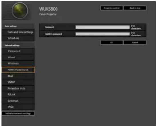
| Item Explanation Factory default setting | ||
| Password Enter the password required for a networked multi-projection connection in 1-byte alphanumeric characters (0 – 15 characters). | ||
| Confirm password For confirmation, enter the same password as you entered in [Password]. | ||
![CANON REALiS WUX6700 - Specifying Networked Multi-Projection Settings [NMPJ Password] - 2](/content/2026/05/965391/images/40a401b32d2404cb3d1fed9f38fc08b15d88d7b046c50cf58466f2af32d12585.jpg)
For details on Networked Multi-Projection (NMPJ), refer to the NMPJ user's manual. User's manual download site: http://www.canon.com/iprj/
Setting Up Email [Mail]
From [Mail] in the settings screen, you can set the items necessary to send error mails and test mails. For the setting procedure, see "Network Setting" (P89).
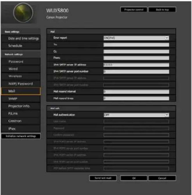
| Item Explanation | Factory default setting | |
| Error report Select whether | to turn the error mail sending function on or off, and IPv4 or IPv6 for the network to use. | OFF |
| To: Enter the recipient address for error mails in 1-byte alphanumeric characters and symbols (1 – 63 characters). | MailUserAccount | |
| Cc: Enter the CC address | for error mails in 1-byte alphanumeric characters and symbols (1 – 63 characters). | |
| From: Enter the sender address for error mails in 1-byte alphanumeric characters and symbols (1 – 63 characters). | Projector@canon.co.jp | |
| IPv4 SMTP server IP address | Enter the SMTP server IP address (IPv4) in 1-byte numbers. | 0.0.0.0 |
| IPv4 SMTP server port number | Enter the SMTP server port number (IPv4) in 1-byte numbers (1 – 65535). | 25 |
| IPv6 SMTP server IP address | Enter the SMTP server IP address (IPv6) in 1-byte numbers. | |
| IPv6 SMTP server port number | Enter the SMTP server port number (IPv6) in 1-byte numbers (1 – 65535). | 25 |
| Mail resend interval* Enter | the interval for resending mail when an error occurred (unit: seconds) within the range of 0 – 59 seconds using 1-byte numbers. | 10 |
| Mail resend times Enter the | e number of times to resend mail when an error occurred within the range of 0 – 255 using 1-byte numbers. | 3 |
* When the interval is set to 0 seconds, repeated attempts to send mail are made (as set in [Mail resend times]) without pausing between attempts.
Mail Authentication Settings
From [Mail auth] under [Mail] in the settings screen, you can configure the settings for authentication of mail that is sent when an error occurs. For the setting procedure, see "Network Setting" (P89).
| Item Explanation | Factory default setting | |
| Mail authentication Select | the mail authentication method. If [OFF] is selected, the other mail authentication settings cannot be changed. | OFF |
| User name Enter the user | name to use for mail authentication in 1-byte alphanumeric characters and symbols (1 – 63 characters). | |
| Password Enter the password | word for mail authentication in 1-byte alphanumeric characters and symbols (1 – 63 characters). | |
| Confirm password For confirmation, enter the same password as you entered in [Password]. | ||
| IPv4 POP3 server IP address | Enter the POP3 server IP address (IPv4) in 1-byte numbers. | 0.0.0.0 |
| IPv4 POP3 server port number | Enter the POP3 server port number (IPv4) in 1-byte numbers (1 – 65535). | 110 |
| IPv6 POP3 server IP address | Enter the POP3 server IP address (IPv6) in 1-byte numbers. | |
| IPv6 POP3 server port number | Enter the POP3 server port number (IPv6) in 1-byte numbers (1 – 65535). | 110 |
| POP before SMTP response time | Enter the SMTP authentication timeout period after POP3 authentication (unit: milliseconds) using 1-byte numbers (0 – 9999 milliseconds). | 300 |
Sending a Test Mail
You can send a test mail to the mail address specified in [Mail] under [Mail] in the settings screen by clicking [Send test mail] at the bottom of the screen.
SNMP Settings [SNMP]
From [SNMP] in the settings screen, you can configure the settings related to control of projectors which use SNMP (Simple Network Management Protocol). For the setting procedure, see “Network Setting” (P89).
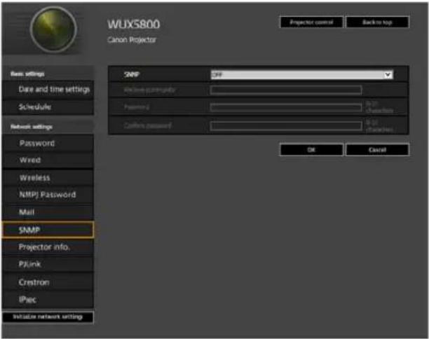
| Item Explanation | Factory default setting | |
| SNMP Select the SNMP function version. If [OFF] is selected, the other settings in this screen cannot be configured. | OFF | |
| Receive community Enter | the community name which will receive projector information in 1-byte alphanumeric characters and symbols (1 – 15 characters). | |
| Password Enter the community settings password in 1-byte alphanumeric characters and symbols (8 – 15 characters). It can be set only when the SNMP version is V3. | ||
| Confirm password For confirmation, enter the same password as you entered in [Password]. | ||
Projector Web Screen Menu
Setting Projector Information [Projector info.]
From [Projector info.] in the settings screen, you can enter relevant comments such as projector names and locations where projectors are installed so that the information can be used to identify projectors when multiple projectors are installed on the network. For the setting procedure, see “Network Setting” (P89).
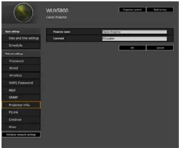
| Item Explanation | Factory default setting | |
| Projector name Enter the | projector name in 1-byte alphanumeric characters and symbols (1 – 63 characters). | Canon Projector001 |
| Comment Enter any relevant notes, such as where the projector is installed. | ||
![CANON REALiS WUX6700 - Setting Projector Information [Projector info.] - 2](/content/2026/05/965391/images/6ac181af278e10c3c16e19e5dcbe169cd093ca9e567137ac29ced63c8acadd85.jpg)
Some characters such as # cannot be used for [Projector name] and [Comment].
Setting PJLink [PJLink]
From [PJLink] in the settings screen, you can set the PJLink functions which are the standard for projector management on a network. For the setting procedure, see "Network Setting" (P89). For information about PJLink, see "What is PJLink?" (P185).
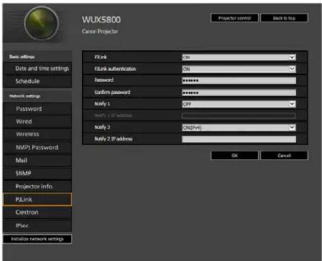
| Item Explanation | Factory default setting | |
| PJLink Turn the PJLink function on or off. If [OFF] is selected, the other settings in this screen cannot be configured. | ON | |
| PJLink authentication Select whether to turn the PJLink authentication function on or off. If [OFF] is selected, it is not possible to change the following items. [Password] [Confirm password] | ON | |
| Password Enter the PJLink authentication password in 1-byte alphanumeric characters (1 – 32 characters). | system | |
| Confirm password For confirmation, enter the same password that you entered in [Password]. | system | |
| Notify 1 Specify whether to send spontaneous state notification. Choosing [OFF] will prevent you from configuring [Notify 1 IP Address]. | OFF | |
| Notify 1 IP Address If [Notify 1] is [ON], specify the IP address to receive notification. | ||
| Notify 2 Configure for notification to multiple recipients. | OFF | |
| Notify 2 IP Address If [Notify 2] is [ON], specify the IP address to receive notification. | ||
Setting Up a Controller Manufactured by Crestron Electronics [Crestron]
The [Crestron e-Control] screen will open. For details on the Crestron Controller, visit the Crestron website.
http://www.crestron.com
Setting Up IPsec [IPsec]
IPsec is a set of protocols designed to prevent the IP packets sent and received over a network from being intercepted, tampered with, or otherwise compromised. Because IPsec adds security to a basic Internet layer, it is intended to ensure security without relying on applications or network configurations.
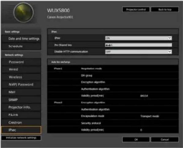
| Item Explanation | Factory default setting | |
| IPsec Select whether to turn the IPsec function on or off. | OFF | |
| Pre-Shared key Enter the pre-shared key used to establish IKE SAs. | ||
| Exempt HTTP from IPsec | Specify whether HTTP communication is exempt from IPsec encryption (ON) or not (OFF). | ON |
![CANON REALiS WUX6700 - Setting Up IPsec [IPsec] - 2](/content/2026/05/965391/images/43a52a8fd7fba5b73ce4429ad0148be11670057f2013cc0c19185372a2373fd6.jpg)
- When IPsec is used, the projector must be configured to match the IPsec operating conditions set on other devices that will communicate with the projector.
- IPsec operating conditions supported by the projector can be checked on the projector's web screen.
- Setting [Exempt HTTP from IPsec] to [OFF] will prevent access to the projector's web screen if IPsec is accidentally enabled on other devices used for communication with the projector.
To avoid blocking access, you can configure this setting to exclude HTTP communication from IPsec. - [Standby power setting] is set to [Normal] and cannot be changed when IPsec is enabled.
- Enabling IPsec will require correct IPsec settings on other devices connected to the projector, such as computers.
- IPsec settings cannot be changed when [DHCP] (IPv4) is enabled.
- When IPsec is enabled, [DHCP] (IPv4) and [Auto settings] (IPv6) cannot be changed.
- When IPsec is enabled, [TCP/IP] (IPv4) and [Manual settings] (IPv6) cannot be changed.
Maintenance / Product Specifications / Troubleshooting
Maintenance
Cleaning the Projector
Clean the projector frequently to prevent dust from settling on the surface.
A dirty lens may ruin the quality of the projected image.
Do not use adhesives, lubricants, oils, or alkaline detergents for maintenance of the projector. They could adhere to the cabinet and damage it, possibly resulting in the projector falling from its mounting and causing an accident or personal injury.
Before cleaning the projector, always turn it off, unplug it after the cooling fan stops, and wait at least one hour. Otherwise, you may get burned because the main unit is very hot immediately after the projector is turned off.
Wipe the projector's main unit softly with a soft cloth.
If the projector is heavily soiled, soak the cloth in water with a small amount of detergent in it, squeeze the cloth thoroughly, and then wipe the projector with it.
After cleaning, wipe the projector with a dry cloth.
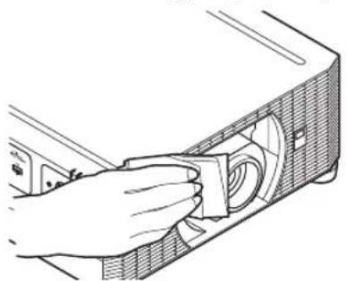
natural_image
Illustration of a hand inserting a component into a device (no text or symbols visible)
- Never use volatile cleaning liquid or benzine, as these may damage the finish of the projector.
- Do not use a chemical dust cloth.
- The lens surface is easily damaged, so do not use a hard cloth or tissues.
Cleaning the Air Filter
The air filter protects the lens and mirror inside the projector from dust and dirt. Should the air filter become clogged with dust, the projector may be damaged since it will block the air flow into the projector and raise the internal temperature of the projector.
The following screen is displayed when turning on the projector if the air filter needs to be cleaned. Clean the air filter if it is displayed.

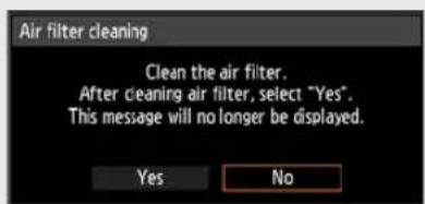
- Only the [◀], [▶], OK and POWER buttons are available while this screen is displayed. (When you press the POWER button, the "Push POWER button again to turn off power." message appears.)
- When this screen has disappeared after being displayed for 10 seconds, all buttons become operable.
- Turn the power of the projector off and pull out the power plug.
- Hook your finger around the air filter handle on the side of the projector and remove the air filter. Use a vacuum cleaner to clean off the dust.
Maintenance
- If the air filter cleaning screen is displayed when turning on the projector after cleaning the air filter, select [Yes] and press the OK button. The air filter counter is reset, and the message is no longer displayed.
- This screen is not displayed when [Air filter warning display] is set to [Off] (P157). Reset the air filter counter manually (P171).

Do not rinse the air filter in water. This may damage the air filter and projector.
Replacing the Air Filter
Follow the procedure below when replacing the air filter.
1 Turn off the projector power and remove the power plug.
2Place your finger on the notch under the filter unit on the side of the projector and pull the filter unit out.
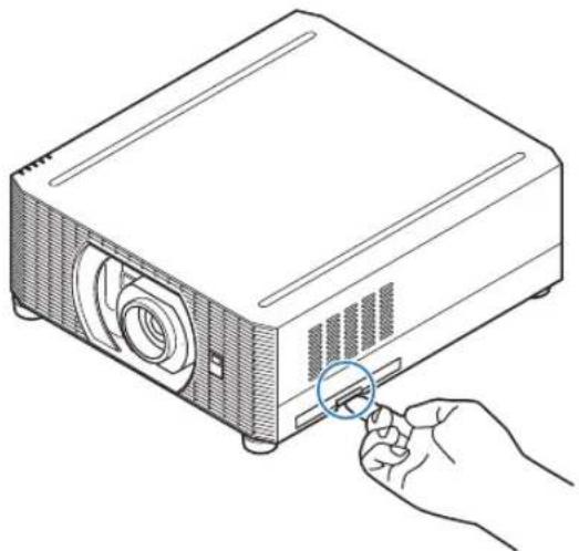
natural_image
Line drawing of a projector with a hand inserting a cable to its base (no text or symbols)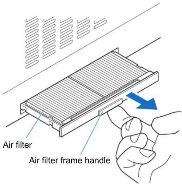
3Press up on the air filter from below and remove it from the air filter frame.
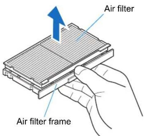
Maintenance
4 Install a new air filter in the air filter frame.
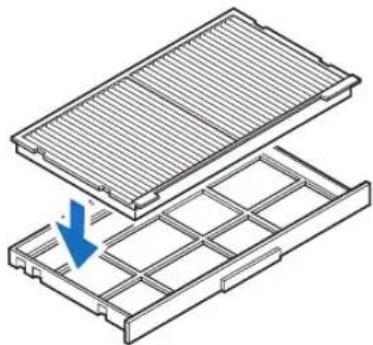
natural_image
Technical illustration of a grid-based component with an arrow indicating downward motion (no text or symbols present)5 Securely insert the frame holding the air filter, all the way into the projector.
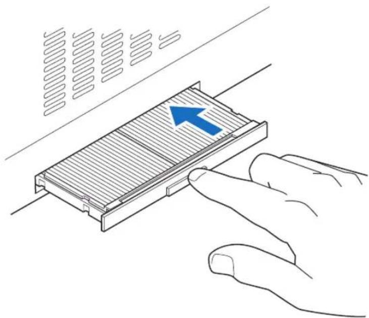
natural_image
Illustration of a hand pressing a component on a surface with a blue arrow indicating direction (no text or symbols)
• After air filter replacement, reset [Air filter counter] (P171).
- Handle the air filter carefully. If damaged, the air filter will not work properly.
- It is recommended that you also replace the air filter when you replace the lamp.
- To purchase a replacement lamp (part no: RS-LP12) and air filter (part no: RS-FL05), contact the Canon Customer Support Center.
Replacing the Lamp
When the usage time of the lamp exceeds a certain amount of time, the following message (two types) is displayed for 10 seconds every time the projector is turned on.
When the time for lamp replacement is near
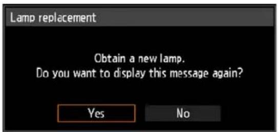
Prepare a new lamp when this screen is displayed.
- Only the [◀], [▶], OK, POWER, FOCUS, ZOOM and LENS SHIFT buttons are available while this screen is displayed.
- When you press the POWER button, "Push POWER button again to turn off power." message appears.
• After this screen has been displayed for 10 seconds and disappeared, all buttons become operable. - This message will not be displayed again if you select [No] in response to the message "Do you want to display this message again?".
When the time for lamp replacement has passed
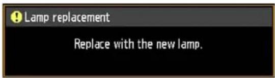
| Guidelines on lamp replacement timing | |
| WUX7500 Approx. | 3000 hours |
| WUX6700 Approx. | 3000 hours |
| WUX5800 Approx. | 3500 hours |
If a lamp replacement message is displayed, see "Lamp Replacement Procedure" (P212).
- Only the POWER, OK, FOCUS, ZOOM and LENS SHIFT buttons are available while this screen is displayed.
- When you press the POWER button, the "Push POWER button again to turn off power." message appears.
- When this screen has disappeared after being displayed for 10 seconds, all buttons become operable.
- You can check the usage time of the lamp in [Lamp counter] in the [System settings] menu (P171).
- This screen is not displayed when [Lamp warning display] is set to [Off] (P157).

- Lamps are more likely to rupture once the lamp replacement message has been displayed. Replace the lamp with a new one as soon as possible.
- The suggested timing for lamp replacement is only a guideline and not a guarantee of how long lamps will last.
- Useful life of lamps varies widely from lamp to lamp and depending on the environment of use. Some lamps may fail or rupture soon after they are first used.
- This projector uses a mercury lamp. Dispose of used lamps in accordance with local regulations.
Replacement Lamp
This projector uses the following lamps.
Lamp part no.: RS-LP12
Contact the Canon Customer Support Center when purchasing a replacement lamp.
Precautions when replacing lamps that stop working
If the illumination suddenly stops when the projector is in use or after you turn it on, the lamp may be broken. In this case, never attempt to replace the lamp by yourself. Always request service from a qualified technician or the Canon Customer Support Center. Additionally, with ceiling-mounted projectors, the lamp may fall out when you open the lamp cover or while you are attempting to replace it. During replacement, make sure no one is under the projector, and stand to the side of the lamp cover, not directly under it.
Before replacing the lamp, always turn off the projector, unplug it after the cooling fan stops, and wait at least one hour. Do not touch the lamp immediately after turning the projector off. It is very hot initially and poses a risk of burns.

- Be sure to use the specified lamp.
- Contact the Canon Customer Support Center for further information. This can also be purchased from the Canon website.
- Do not touch the inner glass surface when you replace the lamp. Doing so may cause deterioration to the projector's performance.
- Handle lamps with care. Impact or abrasion may cause lamps to rupture while they are in use. If a lamp ruptures, contact the Canon Customer Support Center and follow the instructions in “Note the following precautions when replacing lamps that stop working. Failure to do so could result in personal injury.” (P19).
- When replacing the lamp, do not remove any screws other than those specified.
Lamp Replacement Procedure
1 Turn off the projector power and remove the power plug.
2Loosen the screw on the back and open the lamp cover in the direction of the arrow.
The lamp cover screw is attached to the lamp cover and designed to prevent it from falling off.
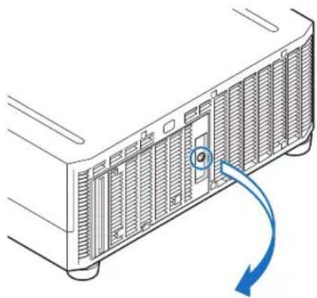
natural_image
Diagram of a server rack with ventilation grilles and a blue arrow indicating clockwise motion (no text or symbols)3Loosen the 3 screws on the inside of the lamp unit, then slowly pull out the lamp unit in the direction of the arrow.
Even when the screws are loosened, they will not fall off the lamp unit.
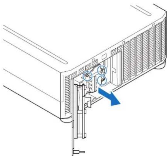
natural_image
Diagram of a server rack with internal components and a blue arrow indicating a loading or movement (no text or symbols present)4 Fully insert a new lamp unit and secure it with the 3 screws.
5Close the lamp cover and tighten the screw.
6Turn on the power. Bring up the menu and select [System settings] > [Other settings] > [Lamp counter].
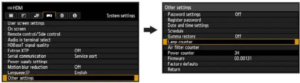
7 Select [Reset] > [Yes] to reset the lamp counter.
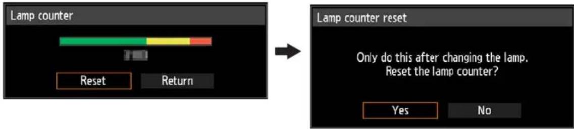
flowchart
graph LR
    A["Lamp counter"] --> B["Color Segment"]
    B --> C["Color Segment"]
    C --> D["Color Segment"]
    D --> E["Reset"]
    D --> F["Return"]
    G["Lamp counter reset"] --> H["Only do this after changing the lamp. Reset the lamp counter?"]
    H --> I["Yes"]
    H --> J["No"]

- It is recommended that you also replace the air filter when you replace the lamp (P207).
- To purchase a replacement lamp (part no: RS-LP12) and air filter (part no: RS-FL05), contact the Canon Customer Support Center.
Product Specifications
■ Supported Signal Types
This projector supports the following signal types.
If your computer or AV equipment is compatible with any one of these signal types, the projector's Auto PC function selects the input signal type to project an image appropriately.
Analog PC
| Resolution (dots) | Signal type | Horizontal frequency (kHz) | Vertical frequency (Hz) |
| 640 x 480 VGA | 31.469 59.940 | ||
| 720 x 480 - 31.469 59.940 | |||
| 720 x 576 - 31.250 50.000 | |||
| 800 x 600 SVGA | 37.879 60.317 | ||
| 848 x 480 - 31.020 60.000 | |||
| 1024 x 768 XGA | 48.363 60.004 | ||
| 1280 x 768 | WXGA | 47.776 59.870 | |
| 47.396 59.995 | |||
| 1280 x 800 | 49.702 59.810 | ||
| 49.306 59.910 | |||
| 1280 x 960 - 60.000 60.000 | |||
| 1280 x 1024 SXGA | 63.981 60.020 | ||
| 1366 x 768 - 47.712 59.790 | |||
| 1400 x 1050 | SXGA+ | 64.744 59.948 | |
| 65.317 59.978 | |||
| 1440 x 900 | WXGA+ | 55.935 59.887 | |
| 55.469 59.901 | |||
| 1600 x 900 - 60.000 60.000 | |||
| 1600 x 1200 UXGA | 75.000 60.000 | ||
| 1680 x 1050 | WSXGA+ | 64.674 59.883 | |
| 65.290 59.954 | |||
| 1920 x 1080 | - | 56.250 50.000 | |
| 67.500 60.000 | |||
| 1920 x 1200 | WUXGA | 74.038 59.950 | |
Digital PC
| Resolution (dots) | Signal type | Horizontal frequency (kHz) | Vertical frequency (Hz) |
| 640 x 480 | D-VGA | 31.469 59.940 | |
| 720 x 480 - 31.469 59.940 | |||
| 720 x 576 - 31.250 50.000 | |||
| 800 x 600 D-SVGA | 37.879 60.317 | ||
| 1024 x 768 | D-XGA | 48.363 60.004 | |
| 1280 x 720 - | 37.500 50.000 | ||
| 45.000 60.000 | |||
| 1280 x 800 | D-WXGA | 49.702 59.810 | |
| 49.306 59.910 | |||
| 1280 x 1024 | D-SXGA | 63.981 60.020 | |
| 1366 x 768 - 47.712 59.790 | |||
| 1400 x 1050 | D-SXGA+ | 64.744 59.948 | |
| 65.317 59.978 | |||
| 1440 x 900 | D-WXGA+ | 55.935 59.887 | |
| 55.469 59.901 | |||
| 1600 x 900 - 60.000 60.000 | |||
| 1600 x 1200 | D-UXGA | 75.000 60.000 | |
| 1680 x 1050 | D-WSXGA+ | 64.674 59.883 | |
| 65.290 59.954 | |||
| 1920 x 1080 | - | 27.000 24.000 | |
| 56.250 50.000 | |||
| 67.500 60.000 | |||
| Resolution (dots) Signal type | Horizontal frequency (kHz) | Vertical frequency (Hz) | |
| 1080PsF(1920 x 1080i) | - | 27.000 24.000 | |
| 28.125 25.000 | |||
| 33.750 30.000 | |||
| 1920 x 1200 D-WU | XGA 74.038 59.950 | ||
HDMI/DisplayPort/HDBaseT
Connecting to a computer
| Resolution (dots) Signal type | Horizontal frequency (kHz) | Vertical frequency (Hz) | |
| 640 x 480 VGA 31 | .469 59.940 | ||
| 800 x 600 SVGA | 37.879 60.317 | ||
| 1024 x 768 XGA | 48.363 60.004 | ||
| 1280 x 800 WXGA | 49.702 59.810 | ||
| 49.306 59.910 | |||
| 1280 x 1024 | SXGA | 63.981 60.020 | |
| 1366 x 768 | - | 47.712 59.790 | |
| 1400 x 1050 | SXGA+ | 64.744 59.948 | |
| 65.317 59.978 | |||
| 1440 x 900 | WXGA+ | 55.935 59.887 | |
| 55.469 59.901 | |||
| 1600 x 900 | - | 60.000 60.000 | |
| 1600 x 1200 | UXGA | 75.000 60.000 | |
| 1680 x 1050 | WSXGA+ | 64.674 59.883 | |
| 65.290 59.954 | |||
| 1920 x 1200 | WUXGA | 74.038 59.950 | |
Connecting with AV equipment
| Signal type | Horizontal frequency (kHz) | Vertical frequency (Hz) |
| 480p | 31.469 | 59.940 |
| 576p | 31.250 | 50.000 |
| 720p | 37.500 | 50.000 |
| 45.000 | 60.000 | |
| 1080i | 28.125 | 50.000 |
| 33.750 | 60.000 | |
| 1080p | 27.000 | 24.000 |
| 56.250 | 50.000 | |
| 67.500 | 60.000 |
Component
| Signal type | Horizontal frequency (kHz) | Vertical frequency (Hz) |
| 480i | 15.734 | 59.940 |
| 480p | 31.469 | 59.940 |
| 576i | 15.625 | 50.000 |
| 576p | 31.250 | 50.000 |
| 720p | 37.500 | 50.000 |
| 45.000 | 60.000 | |
| 1080i | 28.125 | 50.000 |
| 33.750 | 60.000 | |
| 1080p | 56.250 | 50.000 |
| 67.500 | 60.000 | |
| 1080PsF | 27.000 | 24.000 |
| 28.125 | 25.000 | |
| 33.750 | 30.000 |
* The specifications in the table above are subject to change without notice.
* This projector does not support any computer output signal with a dot clock of higher than 162 MHz.
* Use a computer cable in which all pins are connected. If the cable is a type in which all pins are not connected, the image may not be correctly displayed.
■ Projector
| Model name WUX7500 | WUX6700 WUX5800 | |||
| Display system Reflective liquid c | ystal panel (LCOS) : 3 panels | |||
| Optical system | Color separation by dichroic mirror / polarizing beam splitter and color composition by prism | |||
| Display device | Effective display area size 0 | .71" / 16:10 | ||
| Effective number of pixels 2 | ,304,000 (1920 x 1200) | |||
| Other features Active matrix | system | |||
| Projection lens | Zoom (*4) 1.5x (Electric) | |||
| Focus Electric | ||||
| Lens shift (*4)(*5) V: -15% to +55% (Electric), H: ±10% (Electric) | ||||
| Focal length (*4) f = 23.0 to | 34.5 mm (0.9" - 1.4") | |||
| F value (*4) F1.89 to F2.65 | ||||
| Light source | High pressure mercury lamp | 430W 386W | 343W | |
| Image size / Projection distance (*4) | Minimum: 101.6 cm (40") to Maximum: 1524 cm (600"), Projection distance: 1.3 m to 29.0 m (4.3'- 95.1') | |||
| Number of colors 16,770,000 colors | ||||
| Brightness (*1) (*2) 7500lm 6700lm | 5800lm | |||
| Contrast ratio (*1) (*3) | 2000:1 | |||
| Ratio of brightness at periphery to center (*1) (*4) | 90% | |||
| Speaker | 1W, monaural | |||
| Supported input signal types | See “Supported Signal Types” (P214 – P215) | |||
| Display resolution | Computer signal input | Maximum input resolution 1920 x 1200 dots | ||
| Video signal input | Maximum input resolution 1920 x 1200 dots | |||
| Video signals | Analog PC input | WUXGA / UXGA / WSXGA+ / SXGA+ / WXGA+ / FWXGA / WXGA / SXGA / XGA / SVGA / VGA | ||
| Digital PC input | WUXGA / UXGA / WSXGA+ / SXGA+ / WXGA+ / FWXGA / WXGA / SXGA / XGA / SVGA / VGA | |||
| Digital video input | 1080p / 1080i / 720p / 576p / 480p | |||
| Component video input | 1080p / 1080i / 720p / 576p / 576i / 480p / 480i | |||
| Video signal input terminal | Mini D-sub 15-pin | Analog PC, Component | ||
| DVI-I | Digital PC, Analog PC (29-pin DVI connector) | |||
| HDMI | Digital PC, Digital Video | |||
| DisplayPort | Digital PC, Digital Video | |||
| RJ-45 | HDBaseT input (video / audio / control / network) | |||
| Other terminals and connectors | Mini jack | AUDIO IN | ||
| Mini jack | AUDIO OUT | |||
| Mini jack | Wired remote control | |||
| RS-232C | CONTROL (Dsub9) | |||
| USB | USB Type A | |||
| Noise (Lamp mode: Full power / Power saver 1 / Power saver 2) | 40 / 29 / 27 dB | 37 / 29 / 27 dB | 35 / 29 / 27 dB | |
| Operating temperature | 0°C (32°F) to 40°C (104°F) | |||
| Power supply | AC100V to 240V 50 / 60Hz | |||
| Model name WUX7500 | WUX6700 WUX5800 | |||
| Maximum power consumption 555W 495W 455W | ||||
| Power consumption in standby mode | Networking off, Serial communication: Service port | 0.28W | ||
| Networking on, Serial communication: Service port | 1.6W | |||
| Networking off, Serial communication: HDBaseT | 1.5W | |||
| Networking on, Serial communication: HDBaseT | 1.6W | |||
| Standard dimensions | 480 mm (W) x 196 mm (H) x 515 mm (D) / 18.9 (W) x 7.7 (H) x 20.3 (D) in | |||
| Weight Approx. 13 kg / 28.7 lbs (not including projection lens unit) | ||||
| Accessories | Remote control, remote control dry-cell batteries, power cord, Important Information and Warranty Card | |||
| Wireless connectivity | Standards IEEE802.11b/g/n | |||
| Supported channels 1 CH - | 11 CH | |||
| Frequency band 2.4 GHz | ||||
(*1) Compliance with ISO21118-2012
(*2) When using a Standard Zoom Lens (RS-SL01ST) in [Presentation] image mode and [Full power] lamp mode.
(*3) When using a Standard Zoom Lens (RS-SL01ST) in [Presentation] image mode and setting the lamp control to [On].
(*4) When using a Standard Zoom Lens (RS-SL01ST).
(*5) In [Normal] lens shift mode
* 99.99% or more of the LCD panel pixels are effective. During projection, 0.01% or less of pixels may stay lit or unlit due to the characteristics of the LCD panel.
* Using the projector continuously for an extended period of time may accelerate the deterioration of optical parts.
* Product specifications and appearance are subject to change without prior notice.
■ Remote Control
| Type RS-RC07 | |
| Power supply DC 3 | 0V, using two AAA-size batteries |
| Operating range Approx. 8 m ± 25^ horizontal and vertical (to infrared remote receiver) | |
| Dimensions 46.5 mm (W) x 23 mm (H) x 159 mm (D) / 1.8 (W) x 0.9 (H) x 6.3 (D) in. | |
| Weight 56 g / 2.0 oz | |
■ Specification of Each Lens Unit (Option)
| Name Standard Zoom Lens Long Zoom Lens | ||
| Model number RS | SL01ST RS-SL02LZ | |
| External View | 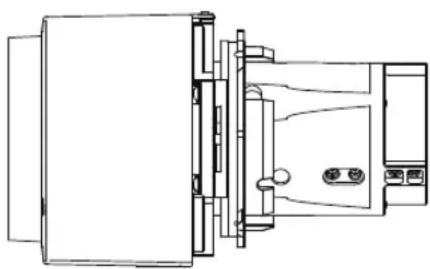 | 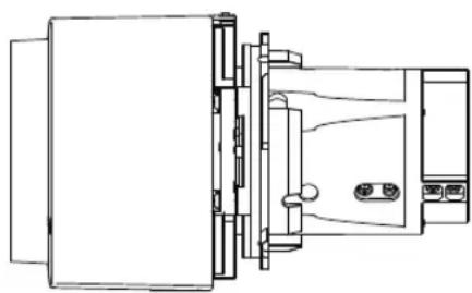 |
| Focal length | 23.0 – 34.5 mm (0.9 – 1.4") | 34.0 – 57.7 mm (1.3 – 2.3") |
| F number 1.89 – 2.65 | 1.99 – 2.83 | |
| Width | 143.4 mm (5.6") | 143.4 mm (5.6") |
| Height | 106.7 mm (4.2") | 106.7 mm (4.2") |
| Length | 175.3 mm (6.9") | 175.3 mm (6.9") |
| Weight | Approx. 725 g (1.6 lbs) | Approx. 925 g (2.0 lbs) |
| Zoom ratio 1.5x | 1.7x | |
| Projection distance | 1.3 – 29.0 m (4.3 – 95.1') | 1.9 – 48.5 m (6.2 – 159.1') |
| Size 100 projection distance | 3.21 – 4.82 m (10.5 – 15.8') | 4.72 – 8.05 m (15.5 – 26.4') |
For details about the amount of lens shift, see "Adjustment Using Lens Shift" (P70).
| Name Ultra-long Zoom Lens Wide Zoom Lens | ||
| Model number RS | SL04UL RS-SL05WZ | |
| External View | 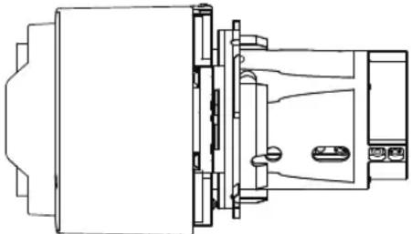 | 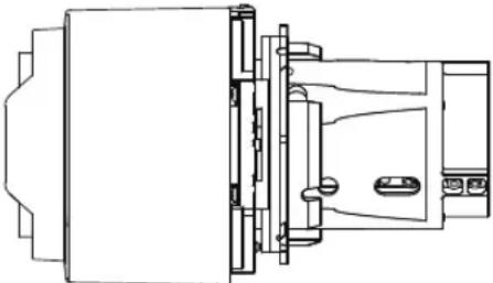 |
| Focal length | 53.6 – 105.6 mm (2.1 – 4.2") | 15.56 – 23.34 mm (0.6 – 0.9") |
| F number 2.34 – 2.81 | 2.09 – 2.34 | |
| Width 143.4 mm (56") | 143.4 mm (5.6") | |
| Height 106.7 mm (4.2") | 106.7 mm (4.2") | |
| Length 183.7 mm (7.2") | 183.7 mm (7.2") | |
| Weight Approx. 110 g (2.4 lbs) | Approx. 1065 g (2.3 lbs) | |
| Zoom ratio | 1.97x | 1.5x |
| Projection distance | 4.6 – 89.0 m (15.1 – 292.0') | 0.9 – 19.5 m (3.0 – 64.0') |
| Size 100 projection distance | 7.64 – 14.94 m (25.1 – 49.0') | 2.15 – 3.23 m (7.1 – 10.6') |
| Name | Short Fixed Lens | Ultra-wide Zoom Lens |
| Model number | RS-SL03WF | RS-SL06UW |
| External View | 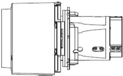 | 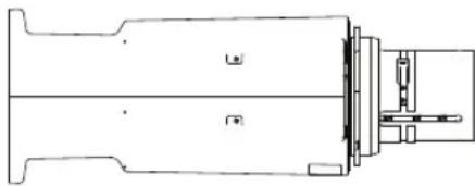 |
| Focal length | 12.8 mm (0.5") | 8.39 mm (0.33") |
| F number | 2.0 | 2.40 |
| Width 143.4 mm (56") | 143.4 mm (5.6") | |
| Height 106.7 mm (4.2") | 113.7 mm (4.8") | |
| Length 175.3 mm (6.9") | 304.3 mm (12.0") | |
| Weight | Approx. 1060 g (2.3 lbs) | Approx. 1520 g (3.3 lbs) |
| Zoom ratio | — | — |
| Projection distance | 0.69 – 5.17 m (2.2 – 17.0') | 0.45 – 3.51 m (1.4 – 11.5') |
| Size 100 projection distance | 1.73 m (5.7') | 1.16 m (3.8') |
For details about the amount of lens shift, see “Adjustment Using Lens Shift” (P70).
■ External View
WUX7500 / WUX6700 / WUX5800
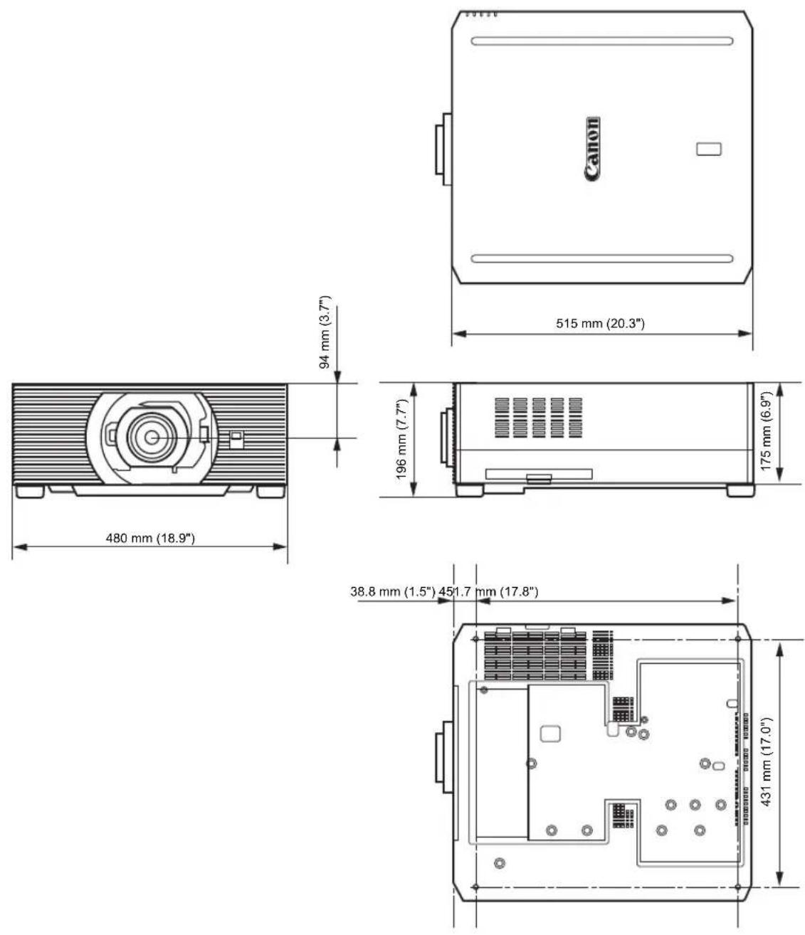
■ Analog PC-2 / COMPONENT Terminal
This terminal is used as a computer ANALOG PC input or COMPONENT input terminal. Use a D-sub computer cable.
The terminal specifications for the ANALOG PC input and COMPONENT input are the same.
Mini D-sub 15-pin
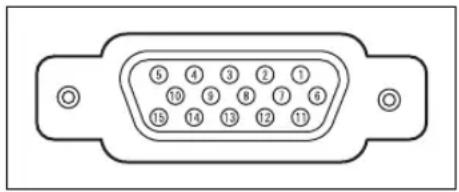
natural_image
Diagram of a 15-pin D-sub connector (no text or symbols)| Pin No. | Signal Pin No. | Signal | |
| 1 R 9 | +5 V power | ||
| 2 | G | 10 | Ground(Vertical sync.) |
| 3 B | 11 Ground | ||
| 4 | OPEN | 12 | DDC data |
| 5 | Ground(Horizontal sync.) | 13 | Horizontal sync. |
| 6 Ground (R) | 14 Vertical sync. | ||
| 7 Ground (G) | 15 DDC clock | ||
| 8 Ground (B) | |||
■ Service Port (CONTROL)
Pin assignment
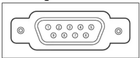
natural_image
Diagram of a 2.5-pin VGA connector (no text or symbols)| Pin No. | Signal |
| 1 | OPEN |
| 2 | RxD |
| 3 | TxD |
| 4 | OPEN |
| 5 | GND |
| 6 | OPEN |
| 7 | Internal pull-up |
| 8 | OPEN |
| 9 | OPEN |
Communication format
Communication mode : RS-232C, asynchronous, half-duplex communication
Communication speed : 19200bps
Character length : 8 bits
Stop bits : Switchable between 1 bit and 2 bits. Factory default, or
state after [Factory defaults] is executed, is 1 bit.
Parity : None
Flow control : None
User commands
| Commands ASCII representation Binary representation | |||
| Power supply | Power on POWER=ON50h 4Fh 57h 45h 52h 3Dh 4Fh 4Eh 0Dh | ||
| Power off POWER=OFF50h 4Fh 57h 45h 52h 3Dh 4Fh 46h 46h 0Dh | |||
| Power status acquisition GET=POWER47h 45h 54h 3Dh 50h 4Fh 57h 45h 52h 0Dh | |||
| Input source | HDMI INPUT=HDMI49h 4Eh 50h 55h 54h 3Dh 48h 44h 4Dh 49h 0Dh | ||
| DisplayPort INPUT=DP49h 4Eh 50h 55h 54h 3Dh 44h 50h 0Dh | |||
| Digital PC INPUT=D-RGB49h 4Eh 50h 55h 54h 3Dh 44h 2Dh 52h 47h 42h 0Dh | |||
| Analog PC-1 INPUT=A-RGB149h 4Eh 50h 55h 54h 3Dh 41h 2Dh 52h 47h 42h 31h 0Dh | |||
| Analog PC-2 INPUT=A-RGB249h 4Eh 50h 55h 54h 3Dh 41h 2Dh 52h 47h 42h 32h 0Dh | |||
| Component INPUT=COMP49h 4Eh 50h 55h 54h 3Dh 43h 4Fh 4Dh 50h 0Dh | |||
| HDBaseT INPUT=HDBT49h 4Eh 50h 55h 54h 3Dh 48h 44h 42h 54h 0Dh | |||
| LAN INPUT=LAN49h 4Eh 50h 55h 54h 3Dh 4Ch 41h 4Eh 0Dh | |||
| USB INPUT=USB49h 4Eh 50h 55h 54h 3Dh 55h 53h 42h 0Dh | |||
| Input source acquisition | GET=INPUT47h 45h 54h 3Dh 49h 4Eh 50h 55h 54h 0Dh | ||
| Image Mode | Standard | IMAGE=STANDARD49h 4Dh 41h 47h 45h 3Dh 53h 54h 41h 4Eh 44h 41h 52h 44h 0Dh | |
| Presentation | IMAGE=PRESENTATION49h 4Dh 41h 47h 45h 3Dh 50h 52h 45h 53h 45h 4Eh 54h 41h 54h 49h 4Fh 4Eh 0Dh | ||
| Dynamic | IMAGE=DYNAMIC49h 4Dh 41h 47h 45h 3Dh 44h 59h 4Eh 41h 4Dh 49h 43h 0Dh | ||
| Video IMAGE=VIDEO49h 4Dh 41h 47h 45h 3Dh 56h 49h 44h 45h 4Fh 0Dh | |||
| Photo/sRGB | IMAGE=PHOTO_SRGB49h 4Dh 41h 47h 45h 3Dh 50h 48h 4Fh 54h 4Fh 5Fh 53h 52h 47h 42h 0Dh | ||
| DICOM Sim | IMAGE=DCM_SIM49h 4Dh 41h 47h 45h 3Dh 44h 43h 4Dh 5Fh 53h 49h 4Dh 0Dh | ||
| User 1 | IMAGE=USER_149h 4Dh 41h 47h 45h 3Dh 55h 53h 45h 52h 5Fh 31h 0Dh | ||
| User 2 | IMAGE=USER_249h 4Dh 41h 47h 45h 3Dh 55h 53h 45h 52h 5Fh 32h 0Dh | ||
| User 3 | IMAGE=USER_349h 4Dh 41h 47h 45h 3Dh 55h 53h 45h 52h 5Fh 33h 0Dh | ||
| User 4 | IMAGE=USER_449h 4Dh 41h 47h 45h 3Dh 55h 53h 45h 52h 5Fh 34h 0Dh | ||
| User 5 | IMAGE=USER_549h 4Dh 41h 47h 45h 3Dh 55h 53h 45h 52h 5Fh 35h 0Dh | ||
| Image mode acquisition | GET=IMAGE47h 45h 54h 3Dh 49h 4Dh 41h 47h 45h 0Dh | ||
| Brightness | Brightness value setting | BRI=0Dh52h 52h 49h 3Dh0Dh | |
| Brightness acquisition GET=BRI47h 45h 54h 3Dh 42h 52h 49h 0Dh | |||
| Sharpness | Sharpness value setting | SHARP= | 53h 48h 41h 52h 50h 3Dh<numeric code>0Dh |
| Sharpness acquisition GET=SHARP47h 45h 54h 3Dh 53h 48h 41h 52h 50h 0Dh | |||
| Contrast | Contrast value setting | CONT= | 43h 4Fh 4Eh 54h 3Dh<numeric code>0Dh |
| Contrast acquisition GET=CONT47h 45h 54h 3Dh 43h 4Fh 4Eh 54h 0Dh | |||
| Aspect | Auto ASPECT=AUTO | AUTO | 41h 53h 50h 45h 43h 54h 3Dh 41h 55h 54h 4Fh 0Dh |
| 4:3 ASPECT=4:3 | 3 | 41h 53h 50h 45h 43h 54h 3Dh 34h 3Ah 33h 0Dh | |
| 16:9 ASPECT=16:9 | 9 | 41h 53h 50h 45h 43h 54h 3Dh 31h 36h 3Ah 39h 0Dh | |
| 16:10 ASPECT=16:10 | 10 | 41h 53h 50h 45h 43h 54h 3Dh 31h 36h 3Ah 31h 30h 0Dh | |
| Zoom ASPECT=ZOOM | ZOOM | 41h 53h 50h 45h 43h 54h 3Dh 5Ah 4Fh 4Fh 4Dh 0Dh | |
| True size ASPECT=TRUE | TRUE | 41h 53h 50h 45h 43h 54h 3Dh 54h 52h 55h 45h 0Dh | |
| Aspect value acquisition GET=ASPECT47h 45h 54h 3Dh 41h 53h 50h 45h 43h 54h 0Dh | |||
| Lamp mode | Full power LAMP=FULL | P=FULL | 4Ch 41h 4Dh 50h 3Dh 46h 55h 4Ch 4Ch 0Dh |
| Power saver 1 | LAMP=ECO1 | 4Ch 41h 4Dh 50h 3Dh 45h 43h 4Fh 31h 0Dh | |
| Power saver 2 | LAMP=ECO2 | 4Ch 41h 4Dh 50h 3Dh 45h 43h 4Fh 32h 0Dh | |
| Lamp mode value acquisition | GET=LAMP | 47h 45h 54h 3Dh 4Ch 41h 4Dh 50h 0Dh | |
| Blank | Blank On | BLANK=ON | 42h 4Ch 41h 4Eh 4Bh 3Dh 4Fh 4Eh 0Dh |
| Blank Off | BLANK=OFF | 42h 4Ch 41h 4Eh 4Bh 3Dh 4Fh 46h 46h 0Dh | |
| Blank acquisition | GET=BLANK | 47h 45h 54h 3Dh 42h 4Ch 41h 4Eh 4Bh 0Dh | |
LED Indicator Details
When there is a problem with the projector, the LED indicator on the side of the projector illuminates or flashes continuously after the projector is turned off.
- Wait until the cooling fan stops and disconnect the power plug from the power outlet before dealing with the problem.
| LED indicator status | Meaning Cause and countermeasure | |
| WARNING and TEMP are lit. | Temperature abnormality | The temperature inside the projector is too high for some reason or the outside air temperature is higher than the operating range. If the problem is inside the projector, check whether the projector is installed and operating normally, unplug the projector from the power outlet to cool down the projector interior and then restart projection. If the air intake or exhaust vent is blocked, remove the obstacle. If the air filter is clogged, clean or replace it (P207). If the same warning occurs again, there may be a malfunction in the projector.* |
| WARNING and LIGHT are lit. | Faulty lamp The lamp does not illuminate. Restart the projector and check whether the lamp illuminates. If the lamp does not illuminate, replace it (P212 – P213). If the same warning occurs again, there may be a malfunction in the lamp drive circuit.* | |
| WARNING (only) flashes 3 times repeatedly. | Filter error The air filter is not installed correctly. Install the air filter correctly and restart the projector. If the same warning occurs again, there may be a malfunction in the projector.* | |
| WARNING flashes 3 times, LIGHT is lit. | Faulty lamp cover | The lamp cover is open. Unplug the projector from the power outlet, then install the lamp cover correctly and turn on the projector again. If the lamp cover has been installed properly, there may be a malfunction in the lamp cover detection switch.* |
| WARNING (only) flashes 4 times repeatedly. | Faulty cooling fan | There may be a malfunction in the cooling fan or another component. Unplug the projector from the power outlet, then plug it back into the outlet and turn on the projector again. If the same warning occurs again, there may be a malfunction in the projector.* |
| WARNING (only) flashes 5 times repeatedly. | Faulty power supply | Abnormal voltage is applied to some parts in the power supply or another failure may have occurred. Unplug the projector from the power outlet, then plug it back into the outlet and turn on the projector again. If the same warning occurs again, there may be a malfunction in the projector. Unplug the projector from the power outlet.* |
| WARNING (only) flashes 6 times repeatedly. | Problem with lens unit installation | The lens unit is not installed correctly. Unplug the projector, install the lens unit correctly, and then plug the projector in again. If the same warning occurs again, there may be a malfunction in the projector.* |
* Contact the Canon Customer Support Center.
Symptoms and Solutions
■ You Cannot Turn on the Projector
| Cause Countermeasure | |
| The power cord is not connected correctly. | Check whether the power cord is connected correctly (P80). |
| The power cord has just been connected. | Wait at least one second after plugging the projector in until you press the POWER button. You cannot turn the projector on immediately after plugging it in (P44). |
| The lamp cover is open. | Unplug the projector from the power outlet, then install the lamp cover correctly and turn on the projector again. |
| The safety device is activated because the air intake or the exhaust vent is blocked and the internal temperature of the projector has increased. | When the safety device is active, the [POWER] indicator does not turn on when you connect the power cord. You cannot disable this safety device. Remove any obstacle that is blocking the air intake or exhaust vent.* |
| The lens unit is not attached correctly. | The lens unit is not installed correctly. Unplug the projector, install the lens unit correctly, and then plug the projector in again. If the same warning occurs again, there may be a malfunction in the projector.* |
| The air filter is not installed correctly. | Check whether the air filter is installed correctly (P208). |
| Key lock is enabled. | Check that Key lock (P158) is not enabled for the projector or the remote control. |
* Contact the Canon Customer Support Center.
■ You Cannot Project an Image from the Projector
| Cause Countermeasure | |
| A cable is not connected correctly. | Check whether the projector is connected to the computer or AV equipment correctly (P76 – P79). |
| 20 seconds have not elapsed since the projector was turned on. | When the projector is turned on, the opening window is displayed for approximately 20 seconds. To project an image immediately, press the OK button on the remote control or side control (P33, P36). |
| No image is sent from the AV equipment. | Check whether an image is played on the connected video camcorder, DVD, etc. |
| Connection with the input terminal has not been performed correctly. | Check whether the AV equipment is connected to the projector input terminal correctly (P35). |
| No input signal type has been selected for the connected AV equipment. | Check that the same input signal has been correctly selected for the connected AV equipment from the [Input] menu (P45). |
| The input signal type is incorrect. | Check whether the selected input signal type is correct (P127, P214). |
| The BLANK function has been selected. | Press the BLANK button on the remote control (P50). |
| No image is projected due to a problem with the computer. | Turn first the projector and then the computer off and then back on again. |
| The external monitor output is not set on the computer correctly. | Turn on the external monitor output on the computer. To turn on the external monitor output, press the [LCD] or [VGA] function key or a key with an icon for the external monitor, while holding down the [Fn] key on the keyboard of the computer. With Windows 10 / Windows 8.1 / Windows 7, you can turn on image output by holding down the Windows logo key and pressing the [P] key.The combination of keys used to perform this operation varies depending on the model of computer. For more detailed information, refer to the manual that came with your computer. |
| The computer is set to dual screen (multi-display) mode. | If dual screen mode is selected, change the computer display output to mirroring mode.The output setting method varies among computer manufacturers. For more detailed information, refer to the manual that came with your computer. |
| The image files are not compatible with USB File Browser. | Projection from USB flash drives requires JPEG images with a resolution not exceeding 10912x8640, single-byte alphanumeric file names, and a FAT-formatted drive. |
| The LAN cable (shielded twisted pair) is not connected correctly. | When [LAN] or [HDBaseT] is selected in the [Input] menu, check whether the LAN cable (shielded twisted pair) is connected to the projector correctly (P81). |
■ There is no Sound
| Cause Countermeasure | |
| The audio cable is not connected correctly. | Check the audio cable connection (P79). |
| The MUTE function is enabled. | Press the MUTE button on the remote control (P37). |
| The volume level is adjusted to the minimum. | Press the VOL button on the remote control or the VOL+ button on the side control to adjust the volume level (P33, P37). |
| An audio cable with a built-in resistor is used. | Use an audio cable without a built-in resistor. |
| Audio in terminal select is [Off]. | Change the Audio In terminal to the appropriate setting (P160). |
■ The Projected Image Is Blurred
| Cause Countermeasure | |
| The image is out of focus. | Adjust the focus (P46). |
| The distance to the screen is too short. | Check whether the distance to the screen is appropriate (P61). |
| The projector is not placed straight in front of the screen. | Check whether the projector is placed obliquely to the screen. A slight error in the projection angle can be corrected through the keystone adjustment function (P101). |
| The projector has been moved to a place where the temperature varies a lot. | When the projector is moved from a location where the temperature is low to a location where the temperature is high, condensation may form on the lens. The condensation will evaporate after a period of time and the projector will be able to project a normal image. |
| The lens is stained. Clean | the lens (P207). |
| The tracking is bad. | Adjust the tracking with the [Auto PC] (P127) or [Tracking] (P128) function. |
| Video is blurred. Activate | motion blur reduction (P163). |
| Motion blur reduction is not available. | Motion blur reduction is not available in projection using USB flash drives or networked multi-projection. |
| The sharpness setting is not available. | Sharpness cannot be adjusted during split-screen display. |
| The lens unit is not installed correctly. | Check whether the lens unit is installed correctly (P65). |
| The lens lever is not engaged. | Check whether the lens unit is installed correctly (P65). |
■ You Cannot Project an Image Appropriately
| Cause Countermeasure | |
| The projected image is inverted in the vertical or horizontal direction. | The ceiling mounted / rear projection setting is incorrect. Check the [Image flip H/V] setting in the [Install settings] menu (P143). |
| The dot clock of the input signal is higher than 162 MHz. | Set the signal dot clock to 162 MHz or less on your computer. |
| A computer cable is used in which some pins are not connected. | Use a computer cable in which all pins are connected. |
■ The Projector Power Turns Off
| Cause Countermeasure | |
| The air intake or exhaust vent is blocked. | Check whether the air intake or exhaust vent is blocked. If the air intake or exhaust vent is blocked, the temperature inside the projector will increase and the power is automatically turned off to protect the projector (The [WARNING] indicator and [TEMP] indicator are lit.). Wait until the projector temperature drops, then make sure that the intake and exhaust vents are not blocked and turn on the projector (P25, P32). |
| The air filter is dirty. Check | whether the air filter is clogged with dust.If the air filter is clogged, clean or replace the air filter (P207, P208). |
| The lamp has ruptured (or there is a lamp malfunction). | If the lamp has ruptured, follow the instructions in “Note the following precautions when replacing lamps that stop working. Failure to do so could result in personal injury.” (P19). |
| The operating environment is inappropriate. | Check whether the operating temperature is between 0°C (32°F) and 40°C (104°F) (P24).Projector settings must be adjusted when using the projector at altitudes of 2,300 m (7,545.8') or higher.In the [Install settings] menu, set [High altitude] under [Professional settings] to [On] (P147). |
■ The Projector Cannot Join the Network
| Cause Countermeasure | |
| The LAN cable (shielded twisted pair) is not connected correctly. | Check whether the LAN cable (shielded twisted pair) is connected to the projector correctly (P81). |
| The projector has not been on long enough (less than about 40 seconds). | Network functions are not available until about 40 seconds after the projector is plugged in. Wait at least 40 seconds, and then try to connect again (P87). |
| The projector cannot join a wireless network. | Follow the instructions in “Network Setting” (P89 – P90), “Wireless LAN (Wi-Fi)” (P29), and “Detailed settings (wireless)” (P180 – P184) to set up the projector again. In PJ AP mode, try changing the wireless channel on the projector (P180 – P184). In infrastructure mode, try changing the wireless channel on the access point. If connection is still not possible, contact the Canon Customer Support Center. |
| A HDBaseT transmitter or similar device is not on. | Check the power of the HDBaseT transmitter. |
■ You Cannot Operate the Remote Control
| Cause Countermeasure | |
| Batteries are not installed properly or they have run out. | Check whether batteries are installed correctly. If batteries are installed correctly, replace them with new batteries (P38). |
| You are operating the remote control from the outside of the remote control operating range. | Check whether you are operating the remote control within the remote control operating range of the main unit of the projector (P39). |
| There is an obstacle between the projector and the remote control. | Remove the obstacle between the infrared remote receiver of the main unit of the projector and the remote control or point the remote control in an obstacle-free path. |
| You are operating the remote control in an unsuitable operating environment. | Check whether the infrared remote receiver of the main unit of the projector is exposed to direct sunlight or strong light of lighting apparatus (P39). |
| The channel setting of the remote control does not match the setting of the projector. | Check whether the channel setting of the remote control has been changed. You can check the [Remote control channel] setting in the [System settings] menu (P159). |
| The key lock function is preventing operation of the remote control. | Check whether [Key lock] is enabled to disable the remote control operation.In the [System settings] menu, set [Key lock] to [Off] (P158). |
| Light from the room lights is entering the infrared remote receiver. | Block the light. |
Safety-Related Symbols on the Product
Any of these symbols on the product have the following meanings.
| Symbol Meaning | |
| “ON” (power) | |
 | “OFF”(power) |
 | Stand-by |
 | “ON/OFF” (push-push) |
 | Earth; ground |
 | Protective earth; protective ground |
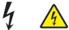 | Dangerous voltage inside.Do not open covers other than instructed. |
 | Caution, hot surface.Do not touch. |
 | Caution, hazardous moving fan blades.Keep away from moving fan blades. |
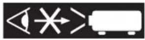 | Caution, very bright light.Do not stare into the beam. |
 | Not for household use. |
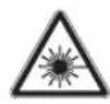 | LASER RADIATION |
Numerics
6-axis color adjust.... 139
A
Adjusting the volume.... 52
Air filter.... 208
Ambient light 137
AMX Device Discovery 186
Analog PC-1 / DVI-I terminal.... 35
Analog PC-2 / COMPONENT terminal.... 35
AUDIO IN terminal 35
AUDIO OUT terminal 35
Auto PC.... 127
B
BLANK 50
Brightness 135
C
Ceiling mounted.... 143
Contrast 135
Crestron RoomView.... 186
D
D. ZOOM.... 53
DICOM SIM.... 48
Digital zoom 36
Direct power on.... 163
Display resolution (Preparing the computer) 46
DVI-I terminal.... 35
Dynamic gamma 138
E
Edge blending.... 5, 106, 148
Effect of ambient light 137
F
FREEZE 50
G
Gamma 136
H
HDBaseT....5, 161
HDBaseT terminal....35, 79, 81
HDMI terminal 35
|
Image adjustment....119, 134
Information 119, 188
Input settings....119, 126
Input terminal 35
Install settings....119, 142
K
Key lock....158
L
Lamp mode 141
Lamp replacement .....210, 212
Language 164
LED indicator....33, 224
Logo display 155
M
Memory color correction....139
MENU....117
Menu 117
MUTE 52
Muting the sound....52
N
Network password....174
Network settings......119, 173
Index
Networked Multi-Projection (NMPJ) 5, 199
Noise reduction.... 137, 138
0
OK.... 36
P
Password 165, 166
PC-free multi projection 131
PJLink 185,203
Power-Saving Settings...... 51
Projecting from Multiple Projectors 112, 131
Projector on.... 155
R
Rear projection.... 143
Remote control.... 36, 38, 159
Reset.... 141, 172
s
Screen color.... 152
Selecting a language 164
Setting display status 126
Sharpness.... 136
Side control.... 33
Signal type 214
Slideshows.... 57, 130, 132
System settings.... 119, 153
T
Terminals and connectors.... 35
Test pattern 105
Tracking 128
U
USB Port 35
V
VOL 52
W
WARNING indicator ....33, 224
Wi-Fi....6
Wired Networks....81, 176
Wireless Networks ....82, 180
Z
Zooming part of an image ....53
- Lamp Part No.: RS-LP12
- Ceiling attachment Part No.: RS-CL15*1
- Ceiling-mount arm Part No.: RS-CL17*1
- Ceiling-mount pipe (350 – 550 mm / 13.8 – 21.7 in) Part No.: RS-CL08*2
- Ceiling-mount pipe (550 – 950 mm / 21.7 – 37.4 in) Part No.: RS-CL09*2
• Air filter Part No.: RS-FL05
- Remote control Part No.: RS-RC07
- Remote control Part No.: RS-RC05
*1 When mounting the projector on the ceiling, both ceiling attachment (RS-CL15) and ceiling-mount arm (RS-CL17) are required.
*2 Use the above materials to hang the projector from the ceiling.
Canon
CANON INC.
30-2, Shimomaruko 3-chome, Ohta-ku, Tokyo 146-8501, Japan
CANON U.S.A. INC.
One Canon Park, Melville, New York 11747, U.S.A.
For all inquires concerning this product, call toll free in the U.S. 1-800-OK-CANON
CANON EUROPE LTD.
3 The Square, Stockley Park, Uxbridge, Middlesex, UB11 1ET United Kingdom
CANON EUROPA N.V.
Bovenkerkerweg 59, 1185 XB Amstelveen, The Netherlands
- MULTIMEDIA PROJECTOR
- WUX7500
- WUX6700
- WUX5800
- User's Manual
- Basic Guide
- Menu Guide
- How to Use This Manual
- This Manual
- Symbols of Button Operations
- Symbols Used in This Manual
- 4K6021Z/4K6020Z/4K5020Z/WUX7000Z/WUX6600Z/WUX5800Z/WUX7500/WUX6700/WUX5800
- Notification of an Addition to Functions with a Firmware Upgrade
- ■ Addition of a Dynamic Contrast Function (4K6021Z/4K6020Z/4K5020Z/WUX7000Z/WUX6600Z/WUX5800Z only)
- ■ Addition of a Set Value Copy Function (Common to All Models)
- Steps to Copy Set Values
- Table of Contents
- Basic Guide ......41
- Installation Guide......60
- Menu Guide ......116
- Projector Highlights
- High-Resolution LCOS Projection
- Peripheral Focus Adjustment
- HDBaseT Input
- Lens Shift
- Motorized Zoom and Focus Adjustment
- Full Range of Lens Units Available
- Superior Video Viewing Experience
- Scheduling
- Edge Blending
- Networked Multi-Projection (NMPJ)
- Wi-Fi Connectivity
- Canon Service Tool for PJ (Canon ST)
- Safety Instructions
- CAUTION
- Safety Precautions
- WARNING:
- CAUTION ON HANGING FROM THE CEILING
- ■ READ AND KEEP THIS OWNER'S MANUAL FOR LATER USE.
- AC Power Cord Requirement
- AC Power Cord for the United States and Canada:
- THE SOCKET-OUTLET SHOULD BE INSTALLED NEAR THE EQUIPMENT AND EASILY ACCESSIBLE.
- Only for European Union and EEA (Norway, Iceland and Liechtenstein)
- Federal Communication Commission Notice
- Safety Symbols in this Manual
- Precautions for Use
- Warning
- Power Supply
- Installation and Use
- RG2-3 label
- Hazard Distance When Equipped with a Replacement Lens (IEC 62471-5)
- Hazard Distance
- Lamp
- Remote Control Batteries
- Handling
- Carrying and Installation
- Precautions When Carrying / Shipping the Projector
- Precautions for Installation
- ■ Do Not Use in the Following Environments
- ■ Do Not Touch the Lens with Bare Hands
- ■ Allow a 30 Min. Warm Up before Focus Adjustment (P46), if Possible
- ■ Install at a Sufficient Distance from Walls and Other Obstructions
- ■ Be Careful of Condensation
- ■ At Altitudes above 2,300 m (7,545.8'), Adjust the Settings
- ■ When Using Mounted on the Ceiling
- ■ Install Facing in the Correct Direction
- Copyright Notice
- Ensure Network Security
- About Trademarks
- Wireless LAN (Wi-Fi)
- ■ Countries and Regions Where Wireless LAN Use Is Permitted
- ■ Model Number
- Statement on EC directive
- Wireless LAN Specifications WUX7500/WUX6700/WUX5800
- FCC/IC NOTICE
- Model: WUX7500/WUX6700/WUX5800 (including WLAN Module Model CH9-1346, FCC ID: AZD221)
- Open Source Software
- Before Use
- Included Accessories
- Projector Part Names and Functions
- ■ Front Side
- ■ Rear Side
- ■ Bottom Side
- ■ Side Control
- ■ LED Indicators
- LED Indicator Displays
- ■ Terminals and Connectors
- LAN / HDBaseT port (P79, P81)
- AUDIO OUT terminal (P79)
- AUDIO IN terminal (P79)
- Terminal for wired remote control (P40)
- DisplayPort port (P77)
- HDMI terminal (P76)
- DVI-I terminal (P77)
- Analog PC-2 / COMPONENT terminal (P78)
- Service port (P221)
- USB port (P54, P112, P131, P171)
- Remote Control
- ■ Part Names and Functions
- ■ Installing Remote Control Batteries
- ■ Remote Control Operating Range
- ■ Using an Optional Wired Remote (RS-RC05)
- Projection Procedure
- Other Projection
- Step 1 Connect Other Equipment
- Step 2 Turn the Projector On
- 1Press the POWER button.
- 2Turn on the computer or other equipment.
- Step 3 Select an Input Signal
- Step 4 Adjust the Image
- ■ Adjusting the Computer's Output Resolution
- ■ Focusing / Resizing the Image
- Step 5 Select the Image Quality (Image Mode)
- ■ Image Modes
- ■ Projecting an Image in the DICOM SIM Mode
- Switching the mode to the DICOM SIM Mode
- As you view the test pattern, perform [Gamma] (P136) adjustment from the [Image adjustment] menu until the image is optimal.
- 4Press the OK button after the setting.
- Turn the Projector Off
- Press the POWER button.
- 2When this window is displayed, press the POWER button again.
- Convenient Projection Features
- Convenient Features
- Temporarily Blacking Out an Image
- Freezing the Picture
- Projecting a Test Pattern from the Menu
- Specifying Power-Saving Settings
- Adjusting the Volume
- Muting the Sound
- Zooming Part of an Image
- Useful when:
- Projecting Images on a USB Flash Drive
- Ending Projection
- ! USB1 USB CARD1
- ■ Description of USB File Browser
- List title
- Drive/file list
- File information area
- File path area
- Preview area (in list view)
- ■ Selecting an Image for Projection
- Selecting a Drive
- Selecting a Folder
- Selecting an Image File for Projection
- Changing the View
- ■ Controlling Images in Full-Screen Projection
- ■ Running a Slideshow of Data Saved in a USB Flash Drive
- Setting a Slideshow Interval
- Projecting Two Images Side by Side
- ■ Switching Input Signals
- Installation Guide
- Relationship Between Projecting Distance and Image Size
- Installing / Removing the Lens Unit
- ■ Installing the Lens Unit
- Removing the Lens Unit
- Installation
- ■ Tabletop or Floor Installation (Lower Than the Screen)
- Press the LENS-SHIFT button on the remote control to display the lens shift adjustment window.
- 2Press the pointer buttons to adjust.
- Adjustment Using Lens Shift
- Area Outside the Lens Shift Range (in [Normal] Lens Shift Mode\*)
- Resetting the Position
- Adjusting Peripheral Focus
- ■ Bringing Image Edges into Focus
- Press the FOCUS button on the remote control twice to display the marginal focus adjustment window.
- Installation Procedure
- 2Press the pointer buttons to adjust the focus at image edges.
- 3Once image edges are in focus, press the OK or FOCUS button.
- ■ Resetting Adjustment
- Adjustment Using the Adjustable Feet
- ■ High Installation, Ceiling Mounting, and Rear Projection
- Press the MENU button on the remote control or projector, and then select [Install settings] > [Image flip H/V].
- 2Select the orientation of how the projector is installed.
- Connection Procedure
- Connecting Other Equipment
- ■ Plugging the Projector In
- Insert the power plug and connector securely up to the base.
- Connecting to a Network
- ■ Network Connection Overview
- ■ Connection Methods
- Wired Networks
- Wireless Networks
- - Projector Access Point (PJ AP) Mode
- • Infrastructure Mode
- Network connection
- - Configuring the Computer’s Network Settings
- Windows 10
- Windows 8.1
- Windows 7
- Mac OS X
- Resetting the IP Address Setting of the Computer
- ■ Setting Up the Network
- Displaying the Network Configuration Screen
- Turn on the computer and projector.
- 2Launch a web browser, enter "http://(projector IP address)" in the address bar, and press the Enter key.
- 3Click [Settings] on the web screen.
- 4Enter the user name and password on the password input window, then click [OK].
- Network Setting
- 3A confirmation window appears. Check the contents and if they are correct, click [Apply].
- Setting Errors
- Resetting Network Settings to the Default Settings
- ■ Error Notification Mails
- Controlling the Projector from a Computer
- 5When the operations are finished, click [Back to top] to return the initial web screen.
- Adjusting the Image
- Filling the Screen
- When projecting to fill a 4:3 screen
- ■ Selecting Screen Aspect
- ■ Selecting an Aspect Ratio
- ■ Relationship between Aspect and Screen Aspect
- Adjusting Keystone Distortion
- ■ Horizontal/Vertical Keystone Correction
- 3Press the pointer buttons to adjust the dimensions, and then press the OK button.
- ■ Corner Adjustment
- Select [Install settings] > [Keystone] > [Corner adjustment].
- Resetting the Keystone Adjustment
- Adjustment Using a Test Pattern
- Special Arrangements
- Projecting from Multiple Projectors at Once (Edge Blending)
- 2Set [Marker] to [On].
- 3In [Side], select [Start position] and use the [ ] ▲[ ] buttons to move the start marker to the outer edge of the overlapping area.
- 4Select [Width] and use the [ ] ▲[ ] buttons to move the end marker to the inner edge of the overlapping area.
- 5Set [Marker] to [Off].
- ■ Adjusting the Overlapping Area
- Matching Colors in the Overlapping Area
- Matching Black in the Overlapping Area
- ■ Making Overlapping Edges Less Noticeable
- Select [Install settings] > [Professional settings] > [Edge blending] > [Adjust] > [Black level adjustment] > [Adjust].
- Set the reference projector's edge-blending markers to [Off] (P106).
- Using PC-Free Multi Projection
- 3Configure some projectors as Secondaries.
- 4Configure one projector as the Primary projector.
- Using Menus
- Press the MENU button to display the menu window.
- 2Press the [ ] /[ ] buttons to select a tab.
- 3Press the [ ] ▲[ ] buttons to select an item.
- 4Select contents.
- Selecting from a list Example: Aspect (P127)
- Adjusting with the [ ]/ [ ]buttons
- Example: Contrast (P135)
- Selecting from a different screen (1)
- Example: Logo capture (P154)
- Selecting from a different screen (2)
- Example: Tracking (P128)
- Information (P188)
- Menu Description
- Input settings
- Aspect
- Auto PC
- Input signal select
- Input signal settings
- Input level
- Super white
- Color space
- Progressive
- Slideshow interval
- Animation effect
- PC-free multi projection
- Mode setting
- Layout pattern setting
- Destination projector setting
- Split screen
- Input signal details
- Image adjustment
- Image mode
- Create profile
- Brightness
- Contrast
- Sharpness
- Gamma
- Color adjustment
- Advanced adjustment
- Ambient light
- Examples of Ambient Light Level Settings
- Random noise reduction
- MPEG noise reduction
- Mosquito noise reduction
- Dynamic gamma
- Colorimetry
- Mem. color correct
- 6-axis color adjust
- Fine-Tune Gamma
- Lamp control
- Lamp mode
- Reset
- Image priority
- Install settings
- Positional lock
- Image flip H/V
- Screen aspect
- Zoom
- Keystone
- Digital image shift
- Professional settings
- RGB alignment
- High altitude
- Lens shift mode
- Marginal focus
- Lens - Position
- Screen color
- Test pattern
- System settings
- User screen settings
- Logo capture
- Logo position
- No signal screen
- Screen when blank
- Projector on
- On screen
- Menu position
- Menu display time
- Guide
- Show input status
- NMPJ standby guide display
- Split screen ID display
- Lamp warning display
- Air filter warning display
- Overheat warning display
- Remote control/Side control
- Beep
- Key repeat
- Key lock
- To Unlock Key Lock Function
- IR receiver settings
- Remote control channel
- Selecting the Projector Channel
- Selecting a Channel on the Remote Control
- [INPUT A-C] button settings
- [Fn] button settings
- Audio in terminal select
- HDBaseT signal quality
- Extron XTP
- Serial communication
- Power supply settings
- Standby power setting
- Power management mode
- Power management duration
- Direct power on
- Motion blur reduction
- Language
- Other settings
- Password settings
- To Cancel the Password
- Register password
- Date and time settings
- Schedule
- Detailed schedule setting
- Option Function
- Gamma restore
- Lamp counter
- Air filter counter
- Power counter
- Firmware
- Factory defaults
- Network settings
- Network settings lock
- Network password setting
- Register network password
- Network (wired/wireless)
- Notes When Connected Wirelessly
- Detailed settings (wired)
- Detailed settings (wireless)
- PJLink
- Sources and corresponding input terminals
- What is PJLink?
- AMX Device Discovery
- Crestron RoomView
- Information
- Checking Projector Information
- Projector Web Screen Menu
- Setting a Password [Password]
- Setting the Date and Time [Date and time settings]
- Setting a Scheduling [Schedule]
- Basic Wired Network Settings [Wired]
- Basic Wireless Network Settings [Wireless]
- Specifying Networked Multi-Projection Settings [NMPJ Password]
- Setting Up Email [Mail]
- Mail Authentication Settings
- Sending a Test Mail
- SNMP Settings [SNMP]
- Setting Projector Information [Projector info.]
- Setting PJLink [PJLink]
- Setting Up a Controller Manufactured by Crestron Electronics [Crestron]
- Setting Up IPsec [IPsec]
- Maintenance / Product Specifications / Troubleshooting
- Maintenance
- Cleaning the Projector
- Cleaning the Air Filter
- Replacing the Air Filter
- Replacing the Lamp
- When the time for lamp replacement is near
- When the time for lamp replacement has passed
- Replacement Lamp
- Lamp Replacement Procedure
- Product Specifications
- ■ Supported Signal Types
- HDMI/DisplayPort/HDBaseT
- ■ Remote Control
- ■ Specification of Each Lens Unit (Option)
- ■ External View
- ■ Analog PC-2 / COMPONENT Terminal
- ■ Service Port (CONTROL)
- Communication format
- LED Indicator Details
- Symptoms and Solutions
- ■ You Cannot Turn on the Projector
- ■ There is no Sound
- ■ The Projected Image Is Blurred
- ■ You Cannot Project an Image Appropriately
- ■ The Projector Power Turns Off
- ■ The Projector Cannot Join the Network
- Safety-Related Symbols on the Product
- Numerics
- A
- B
- C
- D
- E
- F
- G
- H
- |
- K
- L
- M
- N
- Index
- 0
- P
- R
- s
- T
- U
- V
- W
- Z
- Canon
Brand : CANON
Model : REALiS WUX6700
Category : Video projector