TC962 - Démonte-pneus professionnel Sealey - Free user manual and instructions
Find the device manual for free TC962 Sealey in PDF.


| Product Type | Torque Wrench |
| Model | TC962 |
| Brand | Sealey |
| Drive Size | 1/2 inch square drive |
| Torque Range | 20-150 Nm (15-110 lb.ft) |
| Accuracy | ±4% in clockwise direction |
| Length | 450 mm |
| Weight | 1.2 kg |
| Material | Chrome vanadium steel body |
| Handle Type | Reversible ratchet with ergonomic grip |
| Scale Type | Dual scale (Nm and lb.ft) with micrometer adjustment |
| Calibration | Factory calibrated, adjustable via locking collar |
| Storage | Store at lowest torque setting in protective case |
| Warranty | 1 year limited warranty |
| CE Certified | Yes |
| Applications | Automotive, mechanical, and industrial fastening |
| Maintenance | Clean with dry cloth; avoid solvents; periodic recalibration recommended |
| Safety Note | Never exceed maximum torque; use only with impact sockets |
| Packing Contents | Torque wrench, calibration certificate, user manual |
Frequently Asked Questions - TC962 Sealey
User questions about TC962 Sealey
0 question about this device. Answer the ones you know or ask your own.
Ask a new question about this device
Download the instructions for your Démonte-pneus professionnel in PDF format for free! Find your manual TC962 - Sealey and take your electronic device back in hand. On this page are published all the documents necessary for the use of your device. TC962 by Sealey.
USER MANUAL TC962 Sealey
Thank you for purchasing a Sealey product. Manufactured to a high standard this product will, if used according to these instructions and properly maintained, give you years of trouble free performance.

IMPORTANT: PLEASE READ THESE INSTRUCTIONS CAREFULLY. NOTE THE SAFE OPERATIONAL REQUIREMENTS, WARNINGS AND CAUTIONS. USE THE PRODUCT CORRECTLY AND WITH CARE FOR THE PURPOSE FOR WHICH IT IS INTENDED. FAILURE TO DO SO MAY CAUSE DAMAGE AND/OR PERSONAL INJURY AND WILL INVALIDATE THE WARRANTY. PLEASE KEEP INSTRUCTIONS SAFE FOR FUTURE USE.
1. SAFETY INSTRUCTIONS
1.2 GENERAL SAFETY
☐ WARNING! Ensure Health & Safety, local authority, and general workshop practice regulations are adhered to when using this equipment. Under Health and Safety Law, Employers and Self Employed Personnel have a legal duty to ensure Safe Working Conditions for all employees and personnel that may come into contact with this equipment. In particular they must carry out a specific risk and hazard assessment in the workplace to eliminate or reduce any risk found and must record, update and retain records of the results of this inspection.
√ Familiarise yourself with the applications, limitations and any possible or potential hazards of the tyre changer.
√ Maintain the tyre changer in good condition (use an authorised service agent).
√ Replace or repair damaged parts. Use genuine parts only.
Unauthorised parts may be dangerous and will invalidate the warranty.
☐ WARNING! Check regularly for damaged parts. Any part that is damaged must be repaired or replaced before the equipment is next used.
√ Locate the tyre changer in a suitable work area, keep area clean and tidy and free from unrelated materials. Ensure that there is adequate lighting.
☐ WARNING! Use on a level surface, preferably concrete, to which the tyre changer must be bolted.
√ Keep the tyre changer clean for best and safest performance.
√ Wear approved safety eye protection (standard spectacles are not adequate).
3. SPECIFICATIONS
TC961 TC962
| Max. Safe Working Pressure | N/A | 150psi |
| Min. Wheel Diameter | 203mm | 203mm |
| Max. Wheel Diameter | 460mm | 460mm |
| Min. Wheel Depth | 40mm | 40mm |
| Max. Wheel Depth | 203mm | 304mm |
| Working Height | 640mm | 815mm |
2. AIR SUPPLY - TC962 ONLY

2.1. Ensure the air valve is in the "off" position before connecting to the air supply.
2.2. You will require an air pressure between 100 and 150psi.
2.3. □ WARNING! Ensure that the air supply is clean and does not exceed 150psi. Too high an air pressure and/or unclean air will cause excessive wear and may cause damage and/or personal injury.
2.4. Drain the air tank daily. Water in the air line will damage the tyre changer.
2.5. Clean the compressor air inlet filter screen weekly. The recommended hook-up is shown below.
2.6. Line pressure should be increased to compensate for unusually long air hoses (over 8 metres). The minimum hose diameter should be 10mm I.D. and fittings must have the same inside dimensions.
2.7. Keep hose away from heat, oil and sharp edges. Check hoses for wear and make certain that all connections are secure.
√ Keep hands and feet well clear of the bead breaker.
√ Maintain correct balance and footing. Ensure the floor is not slippery and wear non-slip safety shoes.
√ Remove ill fitting clothing. Remove ties, watches, rings, and other loose jewellery and contain and/or tie back long hair.
√ Keep children and unauthorised persons away from the work area.
x DO NOT use the tyre changer for any purpose other than that for which it is designed.
x DO NOT operate the tyre changer if any parts are damaged or missing as this may cause failure and/or personal injury.
x DO NOT allow untrained persons to operate the tyre changer.
x DO NOT stand on the tyre changer.
x DO NOT operate the tyre changer when you are tired or under the influence of alcohol, drugs or intoxicating medication.
MODEL TC962 ONLY
☐ WARNING! Ensure correct air pressure is maintained and not exceeded. Recommended maximum pressure 150psi (10.3 bar).
☐ WARNING! Disconnect the tyre changer from the air supply before changing accessories, servicing or performing any maintenance.
√ Keep air hose away from heat, oil and sharp edges. Check air hose for wear before each use, and ensure that all connections are secure.
x DO NOT yank the hose from the air supply.
x DO NOT direct air from the air hose at yourself or others.
√ When not in use ensure the air supply is turned off.

TC961

TC962
4. OPERATION - TC961
The TC961 Tyre Changer is manually operated - no air supply is required. It is designed for removing/fitting tyres from/to most sizes of open-centre wheels (see Section 3 Specifications). Do not use the tyre changer for any other purpose.
If tyres are to be changed on aluminium wheels the optional tyre bar, Sealey model no. TC963, must be used to prevent damage to the wheel rims.
IMPORTANT! Never attempt to fit or remove a tyre without first lubricating both beads.
4.1. Bead breaking
4.1.1. Deflate the tyre and remove all balance weights.
4.1.2. Lift the bead breaker clear of the tyre changer foot.
4.1.3. Place the wheel on the foot of the tyre changer, locating the rim as indicated. Position the bead breaker spade under the rim flange (fig. 1).
4.1.4. Put the tyre bar into the bead breaker socket.
4.1.5. Pull down firmly on the bar and repeat around the rim until the bead is free.
4.1.6. Turn wheel over and repeat to free the other bead.
Note: When bead breaking on TD or TDX wheels the wheel must be horizontal. Locate the rim on the foot of the tyre changer and support the opposite side of the wheel with a suitable piece of timber.
4.2. Tyre removal
4.2.1. Lubricate both tyre beads with an approved rubber lubricant.
4.2.2. Remove the wheel retaining sleeve from the centre post.
4.2.3. Place the wheel onto the stand with the narrow bead seat uppermost.
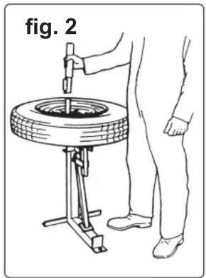
4.2.4. Replace the wheel locating clamp onto the centre post (fig. 2), inserting the wheel peg into one of the wheel mounting holes.
4.2.5. Turn the wheel clockwise on the stand until it locks.
4.2.6. Insert the ball end of the tyre bar beneath the top bead and press the opposite side of the bead down into the wheel well.
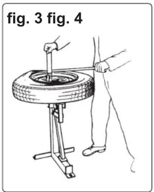
4.2.7. Lever the bar against the wheel location clamp and rotate the bead over the rim (fig. 3).
4.2.8. If a tube is fitted, tighten the locating clamp thumb screw to prevent wheel lifting and then pull out the tube.
4.2.9. Lift the tyre up and repeat the procedure for the lower bead.
4.3. Tyre fitting
4.3.1. Lubricate both tyre beads with an approved rubber lubricant.
4.3.2. Mount and lock the wheel to the stand as in 4.2.2. to 4.2.5.
4.3.3. Place the lower bead of the tyre over the wheel rim and insert the fitting head of the tyre bar between the bead and the rim with the bead on the ledge of the fitting head.
4.3.4. Lever the bar against the wheel location clamp and rotate the bead over the rim (fig. 4).
4.3.5. Fit a tube if appropriate and then seat the upper bead in the same manner.
The TC962 Tyre Changer is air assisted. It is designed for removing/fitting tyres from/to most sizes of open-centre wheels (see Section 3 Specifications). Do not use the tyre changer for any other purpose.
Alloy Wheels. If tyres are to be changed on aluminium wheels the optional tyre bar, Sealey model no. TC963, must be used to prevent damage to the wheel rims (See fig.5b). Use a rim sheild to protect the wheel finish when levering a bead over the wheel rim.
IMPORTANT! Never attempt to fit or remove a tyre without first lubricating both beads.
5.1. Bead breaking (For 18" wheels refer to section 5.4)
5.1.1. Deflate the tyre and remove all balance weights.
5.1.2. Place the wheel under the bead breaker, locating the rim as indicated. Position the bead breaker ram so that the spade is under the rim flange (fig. 5).
Note: Before operating breaker place one foot on the wheel, opposite the spade, to prevent wheel 'kick-up'.
5.1.3. Open the air valve slightly (See fig.5a) to lower the spade - do not use full pressure. Check that the spade is firmly set on the tyre bead, close to the rim and then increase the pressure gradually until the bead breaks free.
5.1.4. Rotate the wheel and repeat around the rim until the whole bead is free.
5.1.5. Turn wheel over and repeat to free the other bead.
Note: When bead breaking on TD or TDX wheels the wheel must be horizontal. Locate the rim on the foot of the tyre changer and support the opposite side of the wheel with a suitable piece of timber.
5.2. Tyre removal
5.2.1. Lubricate both tyre beads with an approved rubber lubricant.
5.2.2. Remove the wheel retaining cone from the centre post.
5.2.3. Place the wheel onto the rubber mat on the stand with the narrow bead seat uppermost.
5.2.4. Replace cone over centre post and fit locating pin though post and both sides of cone tube. (Precautions should be taken to protect the finish of an alloy wheel from the pressure exerted by the cone)
5.2.5. Activate the bead breaker - this will pull down the centre post and so clamp the wheel.
WARNING! Make sure that feet and legs are clear of the spade when carrying out this operation.
5.2.6. Insert the ball end of the tyre bar beneath the top bead and press the opposite side of the bead down into the wheel well.



TC961, TC962 | Issue: 2 - 20/10/09
Tyre bar TC963 for alloy wheels (Optional)
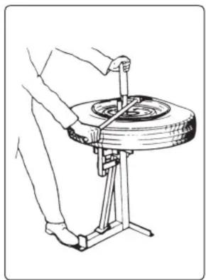
5.2.7. Lever the bar against the cone tube and rotate the bead over the rim (fig. 6).
5.2.8. If a tube is fitted, remove it.
5.2.9. Lift the tyre up and repeat the procedure for the lower bead.
5.3. Tyre fitting
5.3.1. Lubricate both tyre beads with an approved rubber lubricant.
5.3.2. Mount and lock the wheel to the stand as in 5.2.2. to 5.2.5.
5.3.3. Place the lower bead of the tyre over the wheel rim and insert the fitting head of the tyre bar between the bead and the rim with the bead on the ledge of the fitting head.
5.3.4. Lever the bar against the cone tube and rotate the bead over the rim (fig. 7).
5.3.5. Fit a tube if appropriate and then seat the upper bead in the same manner.
fig. 6 fig. 7


5.4 BEAD BREAKING ON 18" WHEELS.
With an 18" wheel resting on the tyre changer foot there is insufficient clearance at 'X' in fig.8 to access the tyre bead. To remedy this situation refer to fig.9. Butt the tyre up against the end of the tyre changer foot as shown at 'B' in fig.9. Take hold of the handle on the ram mechanism and pull it away from the main support so it is at an angle as shown at 'A' with the spade close to the bead. Note: Before operating breaker place one foot on the wheel, opposite the spade, to prevent wheel 'kick-up'. Position the bead breaker ram so that the spade is under the rim flange. Open the air valve slightly to lower the spade - do not use full pressure. Check that the spade is firmly set on the tyre bead, close to the rim and then increase the pressure until the bead breaks free. To proceed refer back to section 5.1.4.

INCORRECT POSITIONING FOR 18" WHEEL

CORRECT POSITIONING FOR 18" WHEEL
NOTE: It is our policy to continually improve products and as such we reserve the right to alter data, specifications and component parts without prior notice.
IMPORTANT: No liability is accepted for incorrect use of this product.
WARRANTY: Guarantee is 12 months from purchase date, proof of which will be required for any claim.
INFORMATION: For a copy of our latest catalogue and promotions call us on 01284 757525 and leave your full name and address, including postcode



Sole UK Distributor, Sealey Group, Kempson Way, Suffolk Business Park, Bury St. Edmunds, Suffolk, IP32 7AR

01284 757500

www.sealey.co.uk

01284 703534

sales@sealey.co.uk
TC961

TC962

Item Part No. Description
- 363/348 Bar, Tyre Fitting/Removing (not shown)
1 363/CE23-1 Wheel Locating Clamp, Thumb
Screw & Wheel Peg
2 363/CE23-2 Screw, Thumb
3 363/CE23-3 Peg, Wheel
4 363/CE23-4 Circlip
5 363/CE23-5 Pin, Bead Breaker
6 363/CE23-6 Nut & Bolt, Bead Breaker
7 363/CE23-7 Breaker, Bead
8 363/CE23-8 Support, Bead Breaker
9 363/CE23-9 Frame, Main
Not supplied with Tyre Changer
- TC963 Tyre Bar, Aluminium Wheels
Item Part No. Description
1 363/348 Bar, Tyre Fitting/Removing
2 363/378 Spring, Return
3 363/379 Lever, Valve
4 363/380 Valve, Control
5 363/400 Mat, Rubber
6 363/402 Ram Assembly Complete
7 363/452 Pin & Chain
8 363/455 Post, Centre
9 363/456 Clamp Assembly, Wheel
10 363/457 Pin & Circlip, Ram
11 363/458 Frame
12 363/459 Hose, Air
13 363/460 Hose, Air, Ram
Not supplied with Tyre Changer
- 363/483 Seal Kit, Ram
- TC963 Tyre Bar, Aluminium Wheels
Version No: 1
Date Issued: 180701


Sole UK Distributor, Sealey Group,
Bury St. Edmunds, Suffolk.
Brand : Sealey
Model : TC962
Category : Démonte-pneus professionnel