
CAGE3 - Electronic Equipment Crestron - Free user manual and instructions
Find the device manual for free CAGE3 Crestron in PDF.


| Product Type | Rack Mount Enclosure |
| Brand | Crestron |
| Model | CAGE3 |
| Form Factor | 3U Rack Height |
| Dimensions (H x W x D) | 5.2 in x 19 in x 12 in (13.2 cm x 48.3 cm x 30.5 cm) |
| Weight | 5 lb (2.3 kg) |
| Material | Steel with black powder coat finish |
| Compatibility | Crestron 3-Series and 4-Series control systems |
| Cooling | Ventilated front and rear panels |
| Mounting | Standard 19-inch rack mount, included hardware |
| Access | Removable front panel for easy module installation |
| Power Supply | None; modules powered separately |
| Operating Temperature | 32°F to 104°F (0°C to 40°C) |
| Storage Temperature | -4°F to 140°F (-20°C to 60°C) |
| Humidity | 10% to 90% (non-condensing) |
| Included Accessories | Mounting screws, rack ears, manual |
| Maintenance | Wipe with dry cloth; avoid solvents |
| Safety | Secure in rack to prevent tipping; follow local codes |
Frequently Asked Questions - CAGE3 Crestron
User questions about CAGE3 Crestron
0 question about this device. Answer the ones you know or ask your own.
Ask a new question about this device
Download the instructions for your Electronic Equipment in PDF format for free! Find your manual CAGE3 - Crestron and take your electronic device back in hand. On this page are published all the documents necessary for the use of your device. CAGE3 by Crestron.
USER MANUAL CAGE3 Crestron
Control Card Expansion Cage for AV3
Installation Guide
This document was prepared and written by the Technical Documentation department at:

CRESTRON®
Contents
Control Card Expansion Cage for AV3: CAGE3 1
Introduction ...... 1
Specifications .... 1
Physical Description....1
Installation 4
Problem Solving....11
Troubleshooting....11
Further Inquiries....11
Future Updates 11
Return and Warranty Policies 12
Merchandise Returns / Repair Service 12
Crestron Limited Warranty....12
The specific patents that cover Crestron products are listed at patents.crestron.com.
Crestron, the Crestron logo, 3-Series, and 3-Series Control System are either trademarks or registered trademarks of Crestron Electronics, Inc. in the United States and/or other countries. Other trademarks, registered trademarks and trade names may be used in this document to refer to either the entities claiming the marks and names or their products. Crestron disclaims any proprietary interest in the marks and names of others.
©2012 Crestron Electronics, Inc.
Control Card Expansion Cage for AV3: CAGE3
Introduction
The CAGE3 is a field installable accessory that adds three control card expansion slots to the AV3 3-Series Control System ^® . The CAGE3 enables installation of up to three 3-Series ^™ control cards to expand the number and types of control ports in the AV3 chassis.
Specifications
Specifications for the CAGE3 are listed in the following table.
CAGE3 Specifications
| SPECIFICATION DETAILS | |
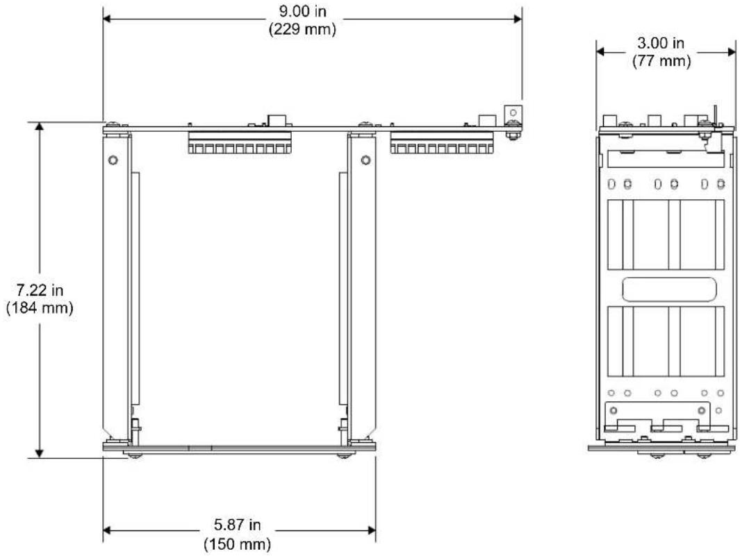
| Dimensions | |
| Height | 3.18 in (81 mm) |
| Width | 9.00 in (229 mm) |
| Depth | 7.22 in (184 mm) |
| Weight | 8 oz (0.23 kg) |
Physical Description
The CAGE3, shown on the following page, contains three 98-pin connectors that accept the plug-in expansion cards and card guides to support each side of the individual cards. A single 98-pin connector provides signal interconnect between the CAGE3 and the AV3 processor board. Two blank faceplates are attached to the CAGE3 when shipped. If more than one plug-in expansion card is to be utilized in the AV3, additional faceplate(s) must be removed. The expansion cards contain two thumbscrews that secure the card faceplate through the CAGE3 faceplate mounting brackets.
CAGE3 Physical View

natural_image
Exterior view of a metal enclosure with green PCB and black connectors (no readable text or symbols)CAGE3 Overall Dimensions (Rear View, As Installed)

CAGE3 Overall Dimensions (Top and Side Views)
CAGE3 Reference Diagram

Installation
The tools required for installation are a #2 Phillips tip screwdriver, a 1/4-inch nut driver or wrench, and a grounding strap.
WARNING: Power must be disconnected during this installation procedure. Disconnect the power cord before opening the cover of the AV3.
CAUTION: The AV3 contains electro-static discharge (ESD) sensitive devices. Perform the following procedure while wearing a grounding strap that is properly grounded or on a grounded work station to avoid damaging the AV3.
CAUTION: To prevent stripping of screw heads, threads, or mounting holes, do not overtighten screws. Tighten only to the specification listed in the individual step(s).
NOTE: During this installation procedure, all screws removed from the AV3 must be retained to install the CAGE3.
NOTE: It is assumed that the AV3 rack ear brackets are not attached during this installation procedure.
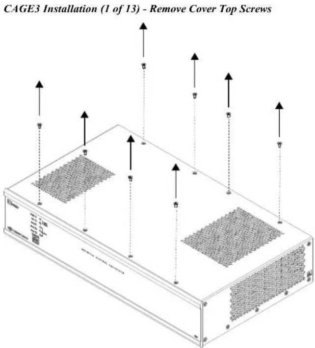
- Refer to the diagram below. Using a #2 Phillips screwdriver, remove eight cover top screws.
- Refer to the diagram below. Using a #2 Phillips screwdriver, remove seven cover screws from each side of the AV3.
CAGE3 Installation (2 of 13) - Remove Cover Side Screws

- Lift and remove AV3 cover.
NOTE: During the next step, the four SEM (attached washer) screws must be retained to install the CAGE3. However, the blank plate is not reused.
- Refer to the diagram below. Use a #2 Phillips screwdriver to remove four rear-mounting SEM screws that secure the AV3 blank plate and remove the plate.
CAGE3 Installation (3 of 13) - Remove Rear-Mounting SEM Screws & AV3 Blank Plate

natural_image
Technical line drawing of a server rack with internal components and ventilation ducts (no text or symbols)NOTE: During the next two steps, the two screws must be retained to install the CAGE3. However, the nut and long standoff are not reused.
- Refer to the diagram below. From inside the AV3, use a 1/4-inch nut driver or wrench to hold the nut of one of the bottom-mounting screws. From the underside of the AV3, use a #2 Phillips screwdriver to remove the mounting screw. Then remove the long standoff mounting screw from under the chassis. Save the #6 flat head screw from the bottom of the chassis.
CAGE3 Installation (4 of 13) - Remove Bottom-Mounting Screws & Nut

natural_image
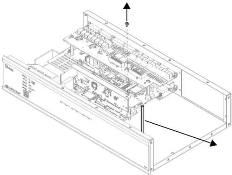
Technical line drawing of a server rack with internal components and ventilation ducts (no text or symbols)- Refer to the diagram below. Remove the #6 screw from the top of the long standoff and discard the standoff. Save the #6 screw from the top of the standoff.
CAGE3 Installation (5 of 13) - Remove Standoff from Chassis
natural_image
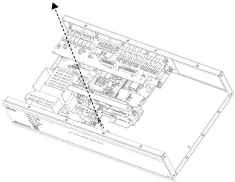
Isometric technical diagram of an electronic device chassis with internal components and mounting brackets (no text or symbols)- Refer to the diagram below. Remove the small #4 screw from the bottom standoff of the chassis and save it to fasten the chassis mounting bracket to the chassis.
CAGE3 Installation (6 of 13) - Remove #4 Screw from Small Standoff
natural_image
Technical line drawing of an electronic device chassis with internal components and a dashed arrow indicating assembly or connection (no text or symbols present)- Refer to the diagram below. Remove the top bracket from the vertical circuit board. Save the two #4 screws for reinstalling the bracket.
NOTE: Do not remove the circuit board.
CAGE3 Installation (7 of 13) - Remove Bracket from Circuit Board

natural_image
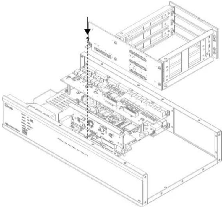
Technical line drawing of an open server rack with internal components and ventilation ducts (no text or symbols)- Install the CAGE3. Refer to the diagram below for correct positioning. Using the small #4 screw saved from step 7, tighten down the chassis mounting bracket to the chassis standoff.
CAGE3 Installation (8 of 13) - Insert CAGE3 into AV3
natural_image
Technical line drawing of an internal server rack with visible circuitry and mounting brackets (no text or labels)- Refer to the diagram below. Reinstall the top bracket to the vertical circuit board using the two #4 screws saved from step 8. Attach the circuit board to the top bracket of the CAGE3 using the #6 screw saved from step 6.
CAGE3 Installation (9 of 13) - Reinstall Circuit Board Bracket

- Refer to the diagram below. Install the two bottom-mounting screws that were removed in step 5 to finger-tight. Then, using a #2 Phillips tip screwdriver, tighten the screws an additional 1/8-turn.
CAGE3 Installation (10 of 13) - Reinstall Bottom-Mounting Screws

natural_image
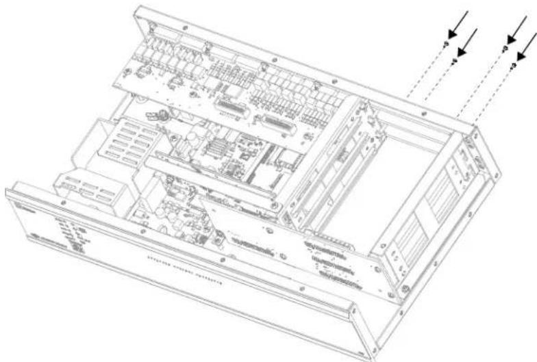
Technical line drawing of an electronic device chassis with internal components and ventilation ducts (no text or labels)- Refer to the diagram below. Use a #2 Phillips tip screwdriver to reinstall and tighten the four rear-mounting screws that were removed in step 4.
CAGE3 Installation (11 of 13) - Reinstall Rear-Mounting Screws
natural_image
Technical line drawing of an internal server rack with ventilation ducts and ventilation grilles (no text or labels)-
Position cover onto the AV3.
-
Refer to the diagram on the following page. Use a #2 Phillips tip screwdriver to reinstall and tighten the seven cover screws that were removed from each side of the AV3 in step 2.
CAGE3 Installation (12 of 13) - Reinstall Cover Side Screws

- Refer to the diagram below. Use a #2 Phillips tip screwdriver to reinstall and tighten the eight cover screws that were removed from the top of the AV3 in step 1.
CAGE3 Installation (13 of 13) - Reinstall Cover Top Screws

natural_image
Isometric diagram of a server rack with multiple ports and mounting points, no text or symbols present- Refer to the installation guide supplied with the expansion card for card installation instructions. If more than one plug-in expansion card is to be utilized in the AV3, additional faceplate(s) of the CAGE3 must be removed.
Problem Solving
Troubleshooting
The following table provides corrective action for possible trouble situations. If further assistance is required, please contact a Crestron ^® customer service representative.
CAGE3 Troubleshooting
| TROUBLE | POSSIBLE CAUSE(S) | CORRECTIVE ACTION |
| Expansion card(s)do not function properly. | CAGE3 interconnect connector J1 pin(s) or AV3 backplane connector damaged. | Inspect connector pins. If damaged, contact Crestron customer service. |
| Expansion card | defective. | Refer to “Troubleshooting” section of the installation guide supplied with the expansion card.* |
* The latest versions of these guides are available from the Crestron Web site (www.crestron.com/manuals).
Further Inquiries
To locate specific information or resolve questions after reviewing this guide, contact Crestron's True Blue Support at 1-888-CRESTRON [1-888-273-7876] or refer to the listing of Crestron worldwide offices on the Crestron Web site (www.crestron.com/offices) for assistance within a particular geographic region.
To post a question about Crestron products, log onto the Online Help section of the Crestron Web site (www.crestron.com/onlinehelp). First-time users must establish a user account to fully benefit from all available features.
Future Updates
As Crestron improves functions, adds new features and extends the capabilities of the CAGE3, additional information may be made available as manual updates. These updates are solely electronic and serve as intermediary supplements prior to the release of a complete technical documentation revision.
Check the Crestron Web site periodically for manual update availability and its relevance. Updates are identified as an “Addendum” in the Download column.
Return and Warranty Policies
Merchandise Returns / Repair Service
- No merchandise may be returned for credit, exchange or service without prior authorization from Crestron. To obtain warranty service for Crestron products, contact an authorized Crestron dealer. Only authorized Crestron dealers may contact the factory and request an RMA (Return Merchandise Authorization) number. Enclose a note specifying the nature of the problem, name and phone number of contact person, RMA number and return address.
- Products may be returned for credit, exchange or service with a Crestron Return Merchandise Authorization (RMA) number. Authorized returns must be shipped freight prepaid to Crestron, 6 Volvo Drive, Rockleigh, N.J. or its authorized subsidiaries, with RMA number clearly marked on the outside of all cartons. Shipments arriving freight collect or without an RMA number shall be subject to refusal. Crestron reserves the right in its sole and absolute discretion to charge a 15% restocking fee plus shipping costs on any products returned with an RMA.
- Return freight charges following repair of items under warranty shall be paid by Crestron, shipping by standard ground carrier. In the event repairs are found to be non-warranty, return freight costs shall be paid by the purchaser.
Crestron Limited Warranty
Crestron Electronics, Inc. warrants its products to be free from manufacturing defects in materials and workmanship under normal use for a period of three (3) years from the date of purchase from Crestron, with the following exceptions: disk drives and any other moving or rotating mechanical parts, pan/tilt heads and power supplies are covered for a period of one (1) year; touch screen display and overlay components are covered for 90 days; batteries and incandescent lamps are not covered.
This warranty extends to products purchased directly from Crestron or an authorized Crestron dealer. Purchasers should inquire of the dealer regarding the nature and extent of the dealer's warranty, if any.
Crestron shall not be liable to honor the terms of this warranty if the product has been used in any application other than that for which it was intended or if it has been subjected to misuse, accidental damage, modification or improper installation procedures. Furthermore, this warranty does not cover any product that has had the serial number altered, defaced or removed.
This warranty shall be the sole and exclusive remedy to the original purchaser. In no event shall Crestron be liable for incidental or consequential damages of any kind (property or economic damages inclusive) arising from the sale or use of this equipment. Crestron is not liable for any claim made by a third party or made by the purchaser for a third party.
Crestron shall, at its option, repair or replace any product found defective, without charge for parts or labor. Repaired or replaced equipment and parts supplied under this warranty shall be covered only by the unexpired portion of the warranty.
Except as expressly set forth in this warranty, Crestron makes no other warranties, expressed or implied, nor authorizes any other party to offer any warranty, including any implied warranties of merchantability or fitness for a particular purpose. Any implied warranties that may be imposed by law are limited to the terms of this limited warranty. This warranty statement supersedes all previous warranties.
This page is intentionally left blank.

CRESTRON®
Crestron Electronics, Inc.
15 Volvo Drive Rockleigh, NJ 07647 (2033001)
Tel: 888.CRESTRON 11.12
Fax: 201.767.7576
www.crestron.com
Installation Guide - DOC. 7331A
Specifications subject to
change without notice.

- Control Card Expansion Cage for AV3
- Installation Guide
- Contents
- Control Card Expansion Cage for AV3: CAGE3 1
- Control Card Expansion Cage for AV3: CAGE3
- Introduction
- Specifications
- Physical Description
- Installation
- Problem Solving
- Troubleshooting
- Further Inquiries
- Future Updates
- Return and Warranty Policies
- Merchandise Returns / Repair Service
- Crestron Limited Warranty
- CRESTRON®
Brand : Crestron
Model : CAGE3
Category : Electronic Equipment