
ED-004 - Industrial network interface Brainboxes - Free user manual and instructions
Find the device manual for free ED-004 Brainboxes in PDF.


| Product Type | Uncategorized Electronic Device |
| Brand | Brainboxes |
| Model | ED-004 |
| Dimensions (approx.) | 100 x 70 x 25 mm |
| Weight (approx.) | 200 g |
| Power Supply | USB 5V or external DC 5-12V |
| Main Functions | Data communication, protocol conversion, signal isolation |
| Interfaces | USB, Serial (RS-232/422/485), Ethernet |
| Operating Temperature | 0°C to 60°C |
| Storage Temperature | -20°C to 70°C |
| Humidity Range | 10% to 90% non-condensing |
| Maintenance & Cleaning | Wipe with dry cloth; do not use solvents |
| Safety Precautions | Keep away from water and extreme temperatures |
| Spare Parts & Repairability | No user-serviceable parts; consult qualified technician |
| General Information | Includes user manual (99 pages); warranty 1 year |
Frequently Asked Questions - ED-004 Brainboxes
User questions about ED-004 Brainboxes
0 question about this device. Answer the ones you know or ask your own.
Ask a new question about this device
Download the instructions for your Industrial network interface in PDF format for free! Find your manual ED-004 - Brainboxes and take your electronic device back in hand. On this page are published all the documents necessary for the use of your device. ED-004 by Brainboxes.
USER MANUAL ED-004 Brainboxes
[rainboxes 9thernet to Digital IO
Contents
1 Introduction....7
2 Before you start....8
2.1 Box Contents....8
2.2 Requirements 8
Supported Operating Systems....8
System Requirements....9
Network Requirements 9
3 Hardware Features....10
3.1 ED Range – Industrial....10
3.2 ED Range – Light Industrial 11
3.3 Usability Features 11
3.4 Technical Specifications....11
Network connection 11
+ower....12
3.5 Storage and Operating Environment Guidelines....12
LED indicators 12
3.6 Circuit Diagrams....13
3.6.1 ED-588....13
3.6.2 ED-516....13
3.6.3 ED-527....14
3.6.4 ED-538....14
3.6.5 ED-038....15
3.6.6 ED-008....15
3.6.7 ED-004....16
3.6.8 ED-204....16
3.6.9 ED-504....17
+in Outs: 18
ED-588 18
ED-527 18
ED-516 18
ED-538 18
□ ED-504 18
3.7 +inouts:....20
3.7.1 Terminal Block Connector +inout (Light Industrial)....21
3.8 RS-232 Standard 21
3.9 Device Dimensions....21
3.9.1 Industrial Devices....21
3.9.2 Light Industrial Devices....22
3.10 Reset Button 22
3.10.1 Manual Reboot 22
3.10.2 Manual Hard Restore....22
3.11 Input/Output Specification 23
3.11.1 ED Range – Industrial....23
3.11.2 ED Range – Light Industrial 23
3.11.3 Relay Information (ED-538, ED-038 Only)....24
3.11.4 ED-538....24
3.11.5 ED-038....24
3.11.6 Firewall Exceptions and +ort Numbers....25
4 Getting Started 26
4.1 Connecting your ED device 26
4.2 Configuring your device settings 27
5 Boost.IO Manager....28
5.1 Introduction....28
5.2 Installing Boost.IO Manager 28
5.3 Finding and Installing an ED device 29
5.4 COM +ort Settings 31
5.4.1 Advanced COM +ort Settings....33
5.4.2 TC+/I+ Settings....33
5.5 Alternate Access Methods....34
5.6 Adding a Device by I+ Address....34
5.7 Adding a Device by MAC Address....36
5.8 I+ Addressing ....38
5.9 Rebooting Device....39
5.10 Restoring Factory Settings....39
5.11 Firmware Upgrade 40
5.12 +roxy Server Settings 42
5.13 Device Swapping....42
5.14 Adding a Remote Device Using Boost.IO 42
5.15 Remote Access....43
6 >eb Configuration +ages 44
6.1 Introduction....44
6.2 Home page....44
6.3 Network page 47
6.4 Serial +ort page....48
6.5 +rotocol page....49
6.5.1 ASCII +rotocol Settings....50
6.5.2 Serial Gateway....51
6.6 Console page....52
6.7 IO Lines page....53
6.8 Device Management page....56
6.9 Factory Default Settings....56
7 Configuration Tables....57
7.1 Baud Rate Settings (BB)....57
7.2 Data Format Settings (FF) 57
7.3 Digital Input/Output Data Characters Format....57
8 ASCII +rotocol ....58
8.1 Introduction....58
Command Format....58
Response Format....59
8.2 Command List....60
8.3 %AANNTTCCFF....61
8.4 #** 62
8.5 #AA00DD....63
8.6 #AA0ADD 64
8.7 #AA0BDD 65
8.8 #AA1cDD....66
8.9 #AAAcDD....67
8.10 #AABcDD....68
8.11 #AAN....69
8.12 \$AA2 70
8.13 \$AA4 71
8.14 \$AA5 72
8.15 \$AA6 73
8.16 \$AAC 74
8.17 \$AACN....75
8.18 \$AAF....76
8.19 \$AALS....77
8.20 \$AAM 78
8.21 \$AAS1....79
8.22 \$AARS....80
8.23 %AA....81
8.24 %AA(Data)....82
8.25 \~AAO(Name)....83
8.26 \~** 84
8.27 \~AA0....85
8.28 \~AA1....86
8.29 \~AA2....87
8.30 \~AA3EΩΩ....88
8.31 \~AA4Ω 89
8.32 \~AA5Ω 90
9 >orked Hardware Examples....91
9.1 Output to a Light Circuit....91
9.2 Switch Input Circuit....91
9.3 Digital Outputs: SINK 91
9.4 Digital Outputs: TTL Compatible....92
9.5 Turning ON Indicator Light....92
9.6 Turning ON Indicator Sounds....93
9.7 Digital Inputs: N+N/+N+ Compatible 93
9.8 Digital Input/Output 94
9.9 Dry Contacts 95
9.10 Detecting Dry Contacts....96
9.11 Dry Contact: +IR Detector....96
9.12 Sensors & Actuators 96
10 Lifetime >arranty and Support....97
11 Regulatory Approvals / Compliance 98
11.1 Company Accreditation 98
11.2 Europe – EU Declaration of Conformity .....98
11.3 >EEE Directive (>aste Electrical and Electronic Equipment)....98
11.4 RoHS Compliance....99
12 Copyright 99
1 Introduction
The *rainboxes \~thernet to @IO products are a range of \~thernet devices controlled by a host computer which provide digital communication functions using Input, Output and Relay lines. The \~@ product range has Input and Output lines which are capable of driving high current and high voltage loads and are specifically designed for use in industrial process control and automation environments.
The \~@ range is designed and built on-site with close collaboration between the hardware and software teams to deliver a product that is both user-friendly and has plenty of functionality.

Fig 1.1. ED Range - Industrial

Fig 1.2 ED Range – Light Industrial
4 Before you start
2.1 Box Contents
The following items are included with your product:
Ethernet Digital Input and/or Output/Relay Device (ED)
Boost.IO Installation CD including manual, Microsoft signed drivers and utilities
Quick Start Guide
Optional Items:
■ Global mains power supply unit - +>-600
USB port power supply – +>-650 – Ideal for powering your ED device from anywhere using your laptop
If any of the items are missing from your box or damaged in anyway please contact support%Brainboxes.com
2.2 Requirements
Supported Operating Systems
The Ethernet to DIO product range can be used in the following Microsoft Operating Systems with the supplied Boost.IO drivers:
indows Server 2012
indows 8.1 32-bit
indows 8.1 64-bit
indows 8 32-bit
indows 8 64-bit
indows 2008 R2
indows 7 32-bit
indows 7 64-bit
■ >indows Server 2008 32-bit
■ >indows Server 2008 64-bit
indows Ωista 32-bit
■ >indows Ωista 64-bit
■ >indows Server 2003 32-bit
■ >indows Server 2003 64-bit
indows X+ 32-bit
indows X+ 64-bit
indows 2000


Brainboxes Boost.IO drivers have undergone extensive Microsoft testing with the ED range. Upon passing these tests, the drivers were signed by Microsoft, as an indication of their quality and stability.
System Requirements
Components: Microsoft .NET Framework 2.0 (installed automatically with Boost.IO package)
indows Installer: >indows Installer 3.1 or later (Recommended)
Internet Explorer: If you are running Internet Explorer, then Internet Explorer 7.0 or later is required
+processor: 400 MHz +entium processor or equivalent (Minimum); 1GHz +entium processor or equivalent (Recommended)
RAM: 96 MB (Minimum); 256 MB (Recommended)
Hard Disk: Up to 500 MB of available space may be required
CD or DΩD Drive: Not required
Display: 800 x 600, 256 colours (Minimum); 1024 x 768 high colour, 32-bit (Recommended)
Network Requirements
Ethernet network connection (wired).
3 Hardware Features
3.1 ED Range – Industrial

3.2 ED Range – Light Industrial

3.3 Usability Features
The ED range has been designed so that it is as easy as possible to wire up the input, output, relay, serial gateway and power wires to the terminal blocks and to connect the network cable:
Removable screw terminal blocks make installation easier and quicker.
Colour coded terminal blocks and ports prevent an incorrect connection. (Industrial only)
Individually numbered pins simplify the wiring and removes confusion. (Industrial only)
Smart Ethernet which automatically detects the polarity of the Ethernet connection so either a straight through or crossover Ethernet cable can be used.
Functional ground to DIN rail.
Can use the 5 Ωolt power from any computer USB port via the optional cable accessory +>-650.
3.4 Technical Specifications
Network connection
- 10Base-T or 100Base-TX Ethernet connection
- Standard 8+8C ("RJ45") socket connector
- TC+/I+ protocol stack
- DHC+ or static I+ address
- Automatic transmit/receive crossover detection
- 1500Ω magnetic isolation
Power
-
ide-range +5 to +30Ω DC 60mA@24Ω 1.4> Typical 120mA@24Ω 2.9> Max
- Reverse voltage protected
- ESD and surge protected
- Earthing connection point

Caution - Do not attempt to operate this product with any other power supply/rating than that specified.
3.5 Storage and Operating Environment Guidelines
| 9D Range – Industrial 9D Range – Light Industrial | ||
| Operating Temperature: | -30°C to +80°C | 0°C to +60°C |
| Storage Temperature: | -40°C to +85°C -40 | °C to +85°C |
| @umidity: 5% to 95% non-condensing | ||
| @ousing: IP 30 rated non-conducting polyamide case with integrated DIN rail mount | ||
L9D indicators
There are 4 LED's on the ED devices representing the status, gateway, Ethernet link and the activity. The table below lists these LEDs, the colours of them and the meaning of the colours.
| Status LED | Green Device Ready | |
| Flashing =ellow Changing Settings | ||
| Flashing between Red & Green Querying IP | ||
| Flashing Green and Red User performing Hard Reset | ||
| Flashing between Green & Red/=ellow | IP address diagnostic | |
| Flashing between Green & =ellow | Initialization diagnostic | |
| Gateway | Flashing Red | RS-485 Comms error |
| Flashing Green | RS-485 | |
| Link LED | Green light on | Network Link Established |
| Flashing Green | Network Data RX/TX | |
| Activity | Flashing Green | Output set / Input Read |
| Flashing Red | Output overload | |
3.6 Circuit Diagrams
As long as you have the relevant jumper set to the 'NPN' position, you do not need an external power supply to use a contact switch. The NPN jumper position puts a pull-up resistor on the input so that you can just wire the switch between the input and ground.
For 9D-588, 9D-527, 9D-516, 9D-504, 9D-538:
hen in RS422/485 mode. There are biasing jumpers for Biasing (B+ and B-) and for Terminating Resistor (T).
These a factory default set in the ON position. (Biasing and Terminating Resistor Enabled). If these jumpers are in the PARK position, then Biasing and Terminating Resistor is Disabled.
9D-588

flowchart
graph TD
    A["Ethernet interface"] --> B["Micro-controller"]
    B --> C["RS-485 interface"]
    C --> D["Power supply"]
    D --> E["Ground"]
    F["D+ D-"] --> G["VA VB"]
    H["GND"] --> I["+5V +3.3V"]
    J["DIn 0"] --> K["Di In 7"]
    L["DIn 7"] --> M["Di In 7"]
    N["DOut 0"] --> O["Di Out 7"]
    P["DOut 7"] --> Q["Di Out 7"]
    R["+5V"] --> S["NPN PNP"]
    T["PARK"] --> U["T B- B+"]
    V["Default position"] --> W["NPN PNP"]
    X["NPN or PNP jumper position should be changed depending on the type of sensor/input."] --> Y["PARK"]
9D-516

flowchart
graph TD
    A["Input"] --> B["Ethernet interface"]
    A --> C["Micro-controller"]
    A --> D["RS-485 interface"]
    A --> E["Power supply"]
    B --> F["Di n 0"]
    C --> G["Di n 15"]
    D --> H["Di n 15"]
    E --> I["Di n 15"]
    J["NPN"] --> K["Di n 0"]
    L["PNP"] --> M["Di n 15"]
    N["PARK"] --> O["T"]
    N --> P["B-"]
    N --> Q["B+"]
9D-527

flowchart
graph TD
    A["Ethernet interface"] --> B["RS-485 interface"]
    C["Microcontroller"] --> B
    D["Power supply"] --> E["+5V"]
    D --> F["+3.3V"]
    G["D+"] --> A
    H["D-"] --> A
    I["VA"] --> A
    J["VB"] --> A
    K["GND"] --> A
    L["DOut 0"] --> M["Diode"]
    N["DOut 15"] --> O["Diode"]
    M --> P["Ground"]
    O --> Q["Ground"]

NPN or PNP jumper position should be changed depending on the type of sensor/input.

NPN or PNP jumper position should be changed depending on the type of sensor/input.
9D-008
- NPN for NPN Input
- PNP for PNP Input
- Off for Output
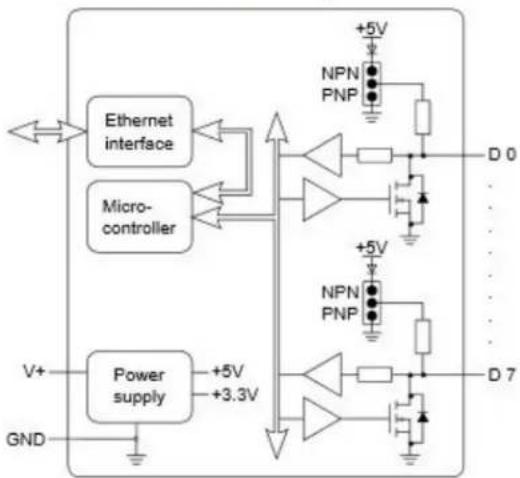
flowchart
graph TD
    A["Ethernet interface"] --> B["Microcontroller"]
    C["Power supply"] --> D["+5V"]
    C --> E["+3.3V"]
    F["NPN PNP"] --> G["+5V"]
    H["NPN PNP"] --> I["+5V"]
    J["D 0"] --> K["Ground"]
    L["D 7"] --> M["Ground"]
    N["GND"] --> O["Ground"]
    P["V+"] --> Q["Ground"]
Default position
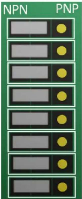
NPN or PNP jumper position should be changed depending on the type of sensor/input.
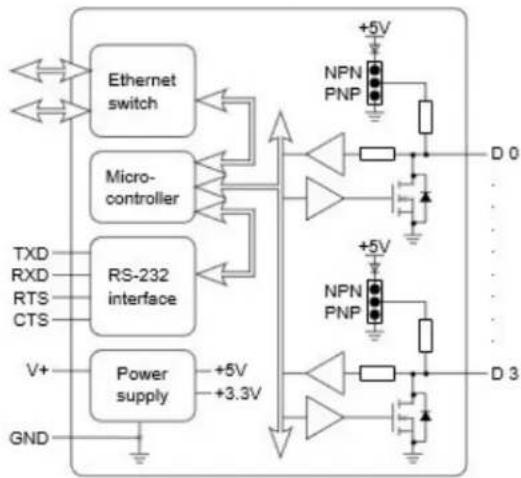
9D8664
• NPN for NPN Input
- PNP for PNP Input
- Off for Output
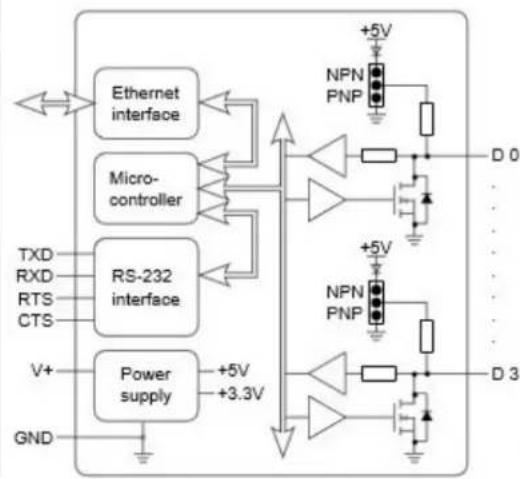
flowchart
graph TD
    A["Ethernet interface"] --> B["Microcontroller"]
    B --> C["RS-232 interface"]
    C --> D["Power supply"]
    D --> E["GND"]
    F["TXD"] --> A
    G["RXD"] --> A
    H["RTS"] --> A
    I["CTS"] --> A
    J["V+"] --> D
    K["GND"] --> D
    L["+5V"] --> M["NPN PNP"]
    M --> N["D 0"]
    O["+5V"] --> P["NPN PNP"]
    P --> Q["D 3"]
Default position
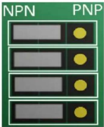
NPN or PNP jumper position should be changed depending on the type of sensor/input.
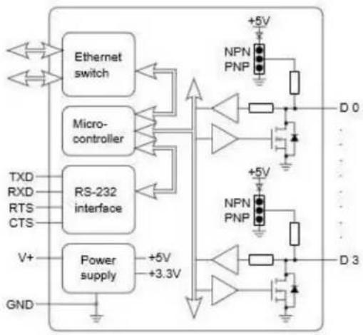
9D8264
• NPN for NPN Input
- PNP for PNP Input
- Off for Output
flowchart
graph TD
    A["Ethernet switch"] --> B["Microcontroller"]
    B --> C["RS-232 interface"]
    C --> D["Power supply"]
    D --> E["GND"]
    F["NPN PNP"] --> G["Diode +5V"]
    H["NPN PNP"] --> I["Diode +5V"]
    J["D 0"] --> K["Ground"]
    L["D 3"] --> M["Ground"]
    N["V+"] --> D
    O["TXD"] --> C
    P["RXD"] --> C
    Q["RTS"] --> C
    R["CTS"] --> C
    S["+5V"] --> T["Diode +5V"]
    U["+3.3V"] --> V["Diode +5V"]
Default position

NPN or PNP jumper position should be changed depending on the type of sensor/input.
9D8564
• NPN for NPN Input
- PNP for PNP Input
- Off for Output
flowchart
graph TD
    A["Ethernet switch"] --> B["Microcontroller"]
    B --> C["RS-232 interface"]
    C --> D["Power supply"]
    D --> E["V+"]
    D --> F["GND"]
    G["NPN PNP"] --> H["D 0"]
    I["NPN PNP"] --> J["D 3"]
    K["+5V"] --> L["Diode"]
    M["+5V"] --> N["Diode"]
    O["+5V"] --> P["Diode"]
    Q["+5V"] --> R["Diode"]
    S["+5V"] --> T["Diode"]
Default position

NPN or PNP jumper position should be changed depending on the type of sensor/input.

Functional 'round is the EARTH connection through the DIN rail that the ED-5xx and ES-5xx is attached to. This Functional Ground (EARTH) on the ED-5xx is on +IN 5 of the BLACK power connector. It is directly connected to the FUNCTIONAL EARTH metal tab on the DIN rail clip. Thus the FUNCTIONAL EARTH electrically connects the metal DIN rail to +IN 5 of the BACK power Connector. The customer can choose to wire or not wire to +IN 5 on the Black power input.
Power 'round is the low side (0Ω) of the power input. The GND on the schematic is connected directly to +IN 1 and +IN 4 of the BLACK power input connector and is thus connected to the low side of the customers power supply.
Signal 'round is applicable to those ED/ES products which have a serial gateway or serial port. (ES-020/357/246/257/701/279/313/320/368/842 and ES-5xx range) This is the ground associated with the data transmission signals- it is typically connected to the cable sheath. It is import to connect this even in twisted pair situations.
ED-588 : 8 digital outputs and 8 digital inputs
| Type of Port | Terminal Block | Pin 1 | Pin 2 | Pin 3 | Pin 4 | Pin 5 |
| Digital Out | Yellow | GND | DOut 0 | DOut 1 | DOut 2 | DOut 3 |
| Digital Out | Orange | GND | DOut 4 | DOut 5 | DOut 6 | DOut 7 |
| Gateway | Grey | GND | RS-485 D- | RS-485 D+ | RS-485 D+ | RS-485 D- |
| Digital In | Green | GND | DIn 0 | DIn 1 | DIn 2 | DIn 3 |
| Digital In | Blue | GND | DIn 4 | DIn 5 | DIn 6 | DIn 7 |
| Power | Black | Power GND | +Vin A | +Vin B | Power GND | Func. GND |
ED-527 : 16 digital outputs
| Type of Port | Terminal Block | Pin 1 | Pin 2 | Pin 3 | Pin 4 | Pin 5 |
| Digital Out | Yellow | GND | DOut 0 | DOut 1 | DOut 2 | DOut 3 |
| Digital Out | Orange | GND | DOut 4 | DOut 5 | DOut 6 | DOut 7 |
| Gateway | Grey | GND | RS-485 D- | RS-485 D+ | RS-485 D+ | RS-485 D- |
| Digital In | Green | GND | DIn 8 | DIn 9 | DIn 10 | DIn 11 |
| Digital In | Blue | GND | DIn 12 | DIn 13 | DIn 14 | DIn 15 |
| Power | Black | Power GND | +Vin A | +Vin B | Power GND | Func. GND |
ED-516
| Type of Port | Terminal Block | Pin 1 | Pin 2 | Pin 3 | Pin 4 | Pin 5 |
| Digital Out | Yellow | GND | DIn 0 | DIn 1 | DIn 2 | DIn 3 |
| Digital Out | Orange | GND | DIn 4 | DIn 5 | DIn 6 | DIn 7 |
| Gateway | Grey | GND | RS-485 D- | RS-485 D+ | RS-485 D+ | RS-485 D- |
| Digital In | Green | GND | DIn 8 | DIn 9 | DIn 10 | DIn 11 |
| Digital In | Blue | GND | DIn 12 | DIn 13 | DIn 14 | DIn 15 |
| Power | Black | Power GND | +Vin A | +Vin B | Power GND | Func. GND |
ED-538
| Type of Port | Terminal Block | Pin 1 | Pin 2 | Pin 3 | Pin 4 | Pin 5 |
| Relay Out | Yellow | RL 0 COM | RL 0 N/O | RL 1 COM | RL 1 N/O | - |
| Relay Out | Orange | RL 2 COM | RL 2 N/O | RL 3 COM | RL 3 N/O | - |
| Gateway | Grey | GND | RS-485 D- | RS-485 D+ | RS-485 D+ | RS-485 D- |
| Digital In | Green | GND | DIn 0 | DIn 1 | DIn 2 | DIn 3 |
| Digital In | Blue | GND | DIn 4 | DIn 5 | DIn 6 | DIn 7 |
| Power | Black | Power GND | +Vin A | +Vin B | Power GND | Func. GND |
9D8564
| PORT | COLOUR | PIN 1 | PIN 2 | PIN 3 | PIN 4 | PIN 5 |
| RS232 | YELLOW | GND | CTS | RXD | RTS | TXD |
| RS422 | YELLOW | GND | RXD- | RXD+ | TXD+ | TXD- |
| RS485 | YELLOW | GND | DATA+ | DATA- | ||
| DIGITAL IO | GREEN | GND | DIO 0 | DIO 1 | DIO 2 | DIO 3 |
| POWER | BLACK | GND | +VIN A | +VIN B | GND | FUNC GND |
3.7 Pinouts:
• ED-008,
• ED-038
• ED-204
• ED-004
ED-008
| Pin | 1 | 2 | 3 | 4 | 5 | 6 | 7 | 8 | 9 | 10 |
| Port | Digital I/O | |||||||||
| Out | DIO 7 | DIO 6 | DIO 5 | DIO 4 | GND | DIO 3 | DIO 2 | DIO 1 | DIO 0 | GND |
ED-038
| Pin | 1 | 2 | 3 | 4 | 5 | 6 | 7 | 8 | 9 | 10 |
| Port | FORM A RELAY | Digital In | ||||||||
| Out | COM 3 | NO 3 | COM 2 | NO 2 | COM 1 | NO 1 | DIO 2 | DIO 1 | DIO 0 | GND |
ED-204
| Pin | 1 | 2 | 3 | 4 | 5 | 6 | 7 | 8 | 9 | 10 |
| Port | RS232 | Digital I/O | ||||||||
| Out | TxD | RxD | RTS | CTS | GND | DIO 3 | DIO 2 | DIO 1 | DIO 0 | GND |
ED-004
| Pin | 1 | 2 | 3 | 4 | 5 | 6 | 7 | 8 | 9 | 10 |
| Port | RS232 | Digital I/O | ||||||||
| Out | TxD | RxD | RTS | CTS | GND | DIO 3 | DIO 2 | DIO 1 | DIO 0 | GND |
Terminal [lock]onnector Pinout (Light Industrial)
Port screw terminal pin outs
![Brainboxes ED-004 - Terminal [lock]onnector Pinout (Light Industrial) - 1](/content/2026/05/964448/images/0ae20e194543d678a365adda6bee987bb00ea0006ba066c0963a8e369cae5c36.jpg)
3.8 RS-232 Standard
The RS-232 standard was introduced in 1962, it is now widely established. RS-232 is a slow speed, short distance, single ended transmission system (i.e. only one wire per signal). Typical RS-232 maximum cable length is 50 feet.
3.9 Device Dimensions
Industrial Devices

Light Industrial Devices

3.10 Reset Button
Manual Reboot
1) +ress the reset button once.
2) The status LED will flash and after 6 seconds the device will reboot.
3) >hen the device is restarted, any connections you have had to the COM ports will need to be re-established.
Manual ©ard Restore
1) +ress and hold the reset button on the device for 6 seconds.
2) The status LED will flash red/green and the device will be restored to factory default settings. For the factory settings, see Factory Default Settings section.
3.11 Input/Output Specification
9D Range – Industrial
| Inputs: ED-588, ED-516, ED-538 |
| NPN/PNP One jumper configures all inputs as either pull up for NPN, active low, type sensors or pull down for PNP, active high, type sensorsLogic Level 0 0Ω to +1Ω maximumLogic Level 1 +3.5Ω to 30Ω maximumLatched Inputs Triggered by user programmable positive or negative edges, stays true until acknowledgedCounter Inputs User programmable – counts positive or negative transitions 0-65335 |
| Outputs: ED-588, ED-527 | |
| Maximum output current | Sinks up to 1Amp per pin 40Ω max loadMax combined load 4.0 Amps per ED device |
| Characteristic Open drain output, protected MosFET with intelligent short circuit protection up to 36ΩOver temperature shutdown: 175°C typical 150°C min | |
| Maximum output load Ωoltage ESD Protection 16kΩ | 40Ω |
9D Range – Light Industrial
| Inputs: ED-008, ED-038 | |
| NPN/PNP One jumper configures each input as either pull up for NPN, active low, type sensors or pull down for PNP, active high, type sensors | |
| Logic Level 0 0Ω to +1Ω maximum | |
| Logic Level 1 +3.5Ω to 30Ω maximum | |
| Latched Inputs Triggered by user programmable positive or negative edges, stays true until acknowledged | |
| Counter Inputs User programmable – counts positive or negative transitions 0-65335 |
| Outputs: ED-008 | |
| Maximum | Sinks up to 0.85Amp per pin 30Ω max load |
| output | Max combined load 4.0 Amps per ED device |
| current | |
| Characteristic Open drain output, protected MosFET with intelligent short circuit protection | |
| Maximum | 30Ω |
| output load | |
| Ωoltage | |
| ESD Protection 16kΩ | |
Relay Information (9D-538, 9D-038 Only)
A relay is an electrically operated switch used to control a circuit by a low power signal giving complete electrical isolation between the control and the controlled circuits. Relays are often used where several circuits must be controlled by one signal.
Relay Outputs 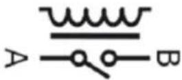 | |
| Relay Type | Form A (SPST-NO: Single Pole Single Throw, Normally Open)When power is removed from the ED-538/ED-038, the relay is open |
| Contact Rating | 5A @ 30VDC5A @ 250VAC |
| Contact Resistance 100mΩ max. (at 1A 24VDC) | |
| Relay Endurance | 100,000 operations at 3A, 30 operations/min, resistive AC load50,000 operations at 5A, 20 operations/min, resistive AC load |
Each relay requires 2 terminal pins:
Pin 1 is COMMON and Pin 2 is NORMALLY OPEN.
The configuration and status of the relays can be viewed in the devices webpage.
9D-538
| Terminal Block | Pin 1 Pin 2 Pin 3 | Pin 4 Pin 5 | |||
| Yellow RL 0 | COM RL 0 N/O RL 1 COM RL 1 N/O | - | |||
| Orange RL 2 | COM RL 2 N/O RL 3 COM RL 3 N/O | - |
9D-038
| Pin 1 | Pin 2 | Pin 3 | Pin 4 | Pin 5 | Pin6 |
| COM 3 | NO 3 | COM 2 | NO 2 | COM 1 | NO 1 |
| Relay 3 | Relay 2 | Relay 1 | |||
Firewall 9xceptions and Port Numbers
hen using the ED Devices with a firewall you may need to manually add the exception entries and port numbers to the firewall list.
Below are the default port numbers and the firewall exceptions.
| Program Name | Default Port Number |
| Device Web Server | 80 |
| TCP Port | 9500 |
| Firmware Upgrade | 67 (BOOTP Server)68 (BOOTP Client)69 (TFTP Port) |
Default >indows Firewall Exception entries:
Brainboxes Boost.IO Suite
Brainboxes Boost.IO Suite (Device Discovery)
(Except >indows X+32 & 64 bits)
U+n+ Framework (>indows X+32 & 64 bits)
Network Discovery (>indows 7 or later)
4 Getting Started
4.1 Connecting your ED device
-
Connect the ED device to your local network using an Ethernet cable and plug into the Ethernet port connection on the device. The ED Ethernet port will automatically detect the polarity of the Ethernet connection so either a straight through or crossover Ethernet cables can be used.
-
Connect a suitable power supply to the ED removable power terminal block.
The optional P>-600 power supply allows the device to be plugged into a standard power socket. Alternatively, the device can be plugged into any USB using the optional P>-650 power cable. ED devices require a power supply providing a minimum of 1.1 watts with an output voltage between +5ΩDC and +30ΩDC.
9D Industrial Range
| POWER TERMINAL PIN OUTS | |||||
| PIN | 1 | 2 | 3 | 4 | 5 |
| FUNCTION | GND | +V_A | +V_B | GND | EARTH |
The ED device is fully operational when only one power supply is attached. >hen only one power supply is being used connect the positive terminal of the power supply to either +ΩA or + ΩB pin and the negative terminal to one of the GND pins.
Two separate sets of power supply inputs terminals are available; one to +ΩA and GND and the other to +ΩB and GND providing redundancy when both are connected. The higher voltage of the two power supplies is selected by the device and in the event of a failure the other supply automatically takes over to keep the device running. The status of the two power supply inputs can be monitored visually via a browser from the ED devices home page and also programmatically.
9D - Light Industrial
| POWER TERMINAL PIN OUTS | |||
| PIN | 1 | 2 | 3 |
| FUNCTION | V + | V - | Earth/Chassis GND |

-
On connecting to the network, the device automatically checks if it is connected to a DHCP Server. If this is the case, the DHCP server will allocate an IP address automatically to the ED device.
-
If no DHCP Server is detected (e.g. you have the ED device plugged directly into the PC), the ED device will default to an IP address of 192.168.127.254 after 60 seconds. If connecting directly to a PC, make sure the PC is on the same 192.168.127.xxx subnet in order to find your device.
-
The LED's will flash when the power is first applied. >hen the status LED turns a steady green (after 5-60 seconds) the device is ready to use.
Make a note of device MAC address (on the side of the ED device, 00-0A-4F-XX-XX) as you will need it to identify the device on your network later.
4.2 Configuring your device settings
There are three methods to view and configure your \~thernet to @IO device. >hich method to use depends on personal preference and convenience.
■ Boost.IO Manager: This is the >indows application that is installed initially to find the device and install the \OM port drivers if required. \configuring from here is the recommended option for ease and convenience, as it centralises all \~thernet to @IO devices in one window. &however, not all of the settings of the \~@ device can be configured from the *oost.IO Manager. See Section 5 for information about *oost.IO Manager.
■ Web Page Interface: This allows the \~thernet to @IO device to be accessed from any +\$ within your network as it does not require *oost.IO Manager. Unlike *oost.IO Manager, every setting can be configured using the web configuration pages. See Section 6 for more information about the web page interface.
ASCII Protocol: The #S\II protocol is a query-response communication protocol which can be used to set all of the protocol settings of the device, send and read data, and get status information from the devices. To send the commands and receive responses a connection to the device needs to be set up. This can be done using either a T\+ connection or through the \$OM port.
5 Boost.IO Manager
5.1 Introduction
Boost.IO Manager is a graphical user interface application which will allow you to find your Brainboxes ED device on a network and then configure some of the settings in >indows. As part of the Boost.IO application a COM port can be installed which allows communication with the device using the ASCII protocol.
Boost.IO Manager is not required if you want to communicate with the device using just the I+ address or if you want to configure the device only using the web configuration pages.
Boost.IO Manager can be found on the CD that was packaged with your device.
5.2 Installing Boost.IO Manager
Insert the CD into your +C
Browse the contents of the CD and locate the "Setup" program on the CD and double click to launch. +receed to Step 3.
Click 'Install' to launch the Boost.IO setup program.
Follow the on screen instructions to install the Boost.IO application.

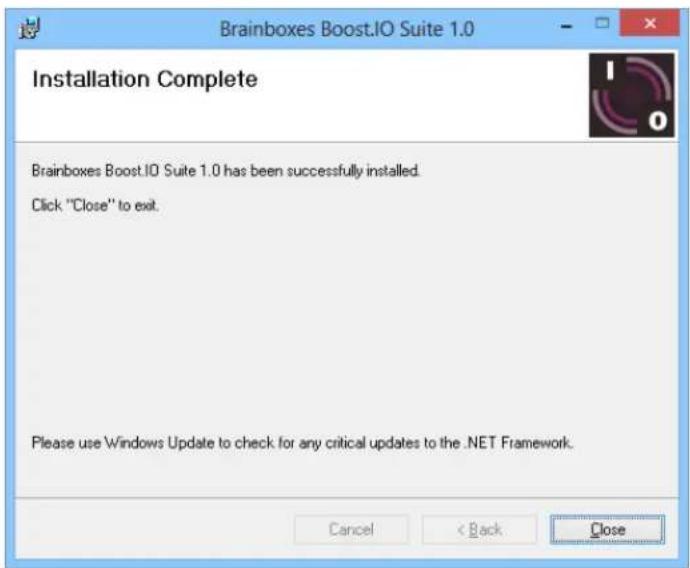
Once the installation process is complete you will see the setup wizard now says "Installation Complete" and there will be a Boost.IO Manager icon on your desktop.
5.3 Finding and Installing an ED device
When using the ED device with Boost.IO Manager a COM port can be installed which allows the user to send ASCII commands to the device using a COM port connection.
- Open Boost.IO Manager by double clicking the Boost.IO Manager icon on your desktop.
- Click 'File' > 'Find Devices' to search for devices on the network (or press F5). This will find any ED devices on the same subnet as your PC. If your device is on a different subnet, please see the section entitled "Adding a Device by IP Address".

-
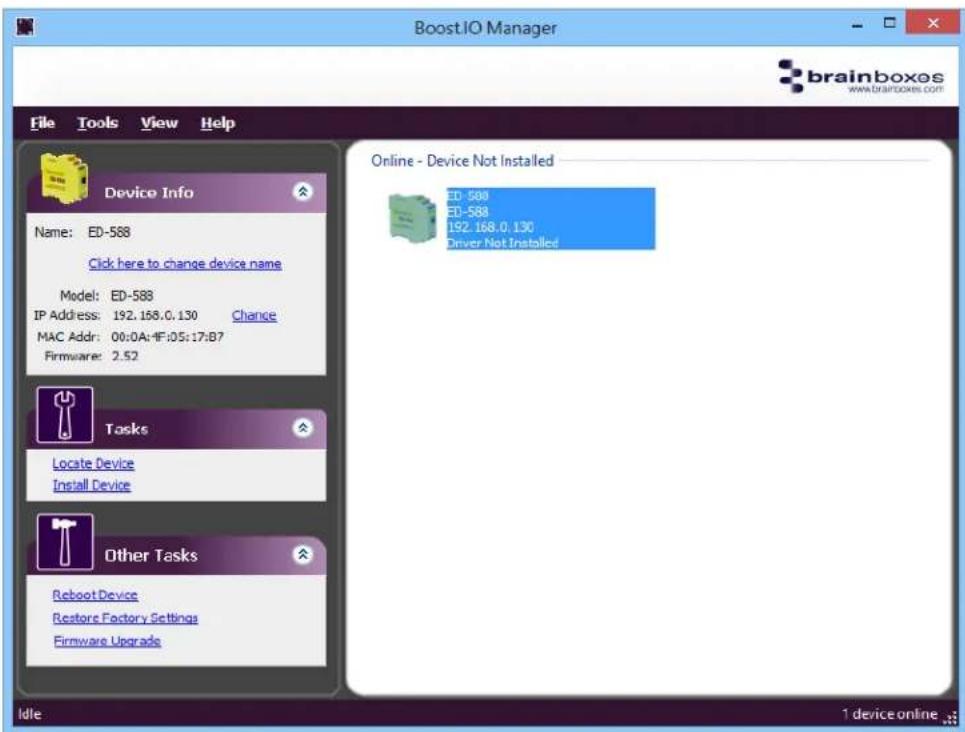
Once the search is complete, all the devices that have been found on the network will be displayed in the main window of Boost.IO Manager. When you select a device, the information and settings options for that device will appear in the left column.
-
=ou can identify your ED device by matching the MAC address in the left panel of Boost.IO Manager with the MAC address on the sticker of your ED device's case.
-
hen you have found your device in Boost.IO Manager, in the left panel under 'Tasks' click 'Install Device'.

- The driver for the device will be installed and, when complete, the icon in Boost.IO Manager will have a blue tick next to it and the status will be 'Ready'.

- There will now be a COM +orts section in the left panel which allows you to change the settings of the installed COM +ort such as baud rate and COM label. For details on how to do this please see the COM +ort Settings section.
5.4 COM Port Settings
To change the COM +ort settings of an installed ED device, follow the steps below.
- Open Boost.IO Manager, if it is not already open, by clicking the Boost.IO icon on your desktop.
- Select the installed device which you want to configure by clicking on it.
- In the left panel find the 'COM +orts' section and double click on the port which you want to configure.

- =ou will then see the port properties dialog box. Click on the '+ort Settings' tab, then click the 'Configure Settings.' button.
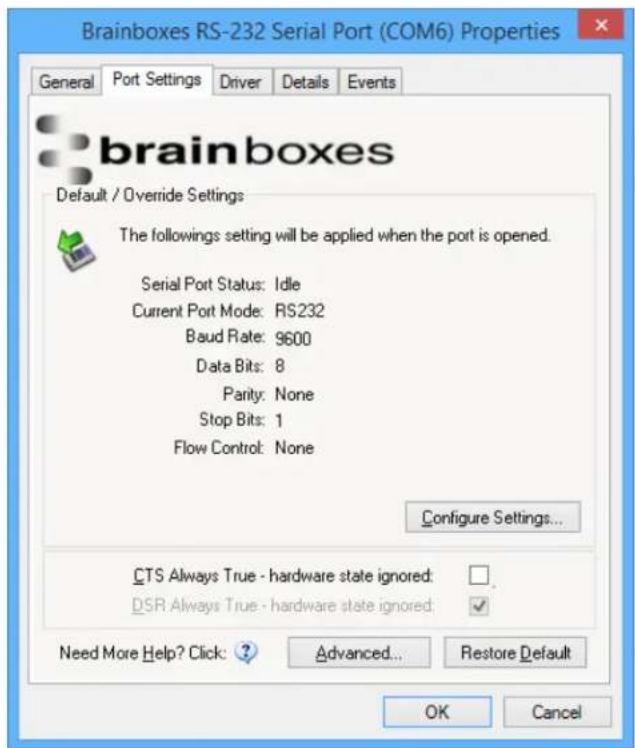
- A webpage will be opened which allows you to configure all of the devices settings. For more information on configuring the device using the web configuration pages please see section 7. >eb Configuration +ages
]TS \*Iways True
- CTS is an incoming hardware handshaking line. This means it receives a signal from the connected device which tells the ED device when it is and isn't OK to send data out the RS232 port.
Sometimes these signals may want to be ignored. By forcing CTS True, the ED device will ignore those signals and always send data.
These settings are especially helpful when CTS is not physically connected (such as in a 3 wire setup) and it is not acceptable for the data flow to stop and start due to arbitrary variances on the unconnected signal lines.
\*dvanced ]OM Port Settings
From the +ort Settings tab, you can get to the advanced settings for the COM port by clicking the 'Advanced...' button. This will open another dialog window allowing you to change the advanced settings for the COM port.

]OM Number
The COM +ort Number is changed using the drop down box on this page. Click the drop down box and select a COM +ort Number from the list. If the COM +ort number is labelled "in use", it is either currently used by a COM +ort present on the system, or is reserved for a device which is not currently present. It is possible to select this COM number and force the change if you are sure it is not required by any other device. Click the 'OK' button to apply the changes.
Port \*accessible When Device is Offline
ith ED devices being connected through a network, whenever a device is unplugged the device will go offline in Boost.IO Manager and any COM ports that are installed will become unavailable. By ticking this checkbox, it will keep the COM port available to use the port, even if the ED device is offline. This is useful if the device is being used in an application that requires a constant connection to a COM port.
T]P7IP Settings
Under the 'TC+/I+ Settings' tab is information about the ED device. There is also a connection attempt timeout field. This value is the time that the driver will attempt to connect to the device COM port before giving up. For example, if this value is set at 6 seconds, the driver will attempt to connect to the COM port for 6 seconds. If no connection could be made after 6 seconds, then the driver will stop attempting to connect.
If this value is set to 0, the driver will attempt to connect without ever giving up.

5.5 Alternate Access Methods
There are three methods to view and configure your Ethernet Device once it's installed on the target +C. >which method to use depends on personal preference and convenience.
N[: Only certain settings can be configured using the >eb +age Interface
■ [oost.IO Manager: This is the application that is installed initially to find the device and install the COM port drivers. Configuring from here is the recommended option for ease and convenience, as it centralises all ED devices.
Windows Device Manager: This is the standard >indows Control +anel that allows users to view and control all hardware attached to a computer. The ED devices ports can be configured from here also.
■ Web Page Interface: This allows the ED device to be accessed from any +C within your network as it does not require Boost.IO Manager. Configuration from here is recommended for socket based applications only.
5.6 Adding a Device by IP Address
=ou may already know the I+ address of the device that you are using. This might be because the device has had an I+ address reserved for it by a system administrator or you are remotely connecting to the device. Using the I+ address of the device, you can add it manually into Boost.IO Manager.
-
Open Boost.IO Manager by clicking the icon created on the desktop when the application was installed.
-
Select 'Tools' and then click 'Add Device Manually'.

- Enter the I+ address and port number of the device into the Device I+ Address box the click the 'Next' button.

- Enter the ASCII +rotocol +ort number into box. The default +ort Number is 9500.

- Click 'Add' and the device will be added to the Boost.IO Manager window.
5.7 Adding a Device by MAC Address
A device can be added into Boost.IO Manager by entering the MAC address. The MAC address of a device can be found on the sticker of the device. Follow the instructions below to add the device using the MAC address.
Open Boost.IO Manager by clicking the icon created on the desktop when the application was installed.
Select 'Tools' and then click 'Add Device Manually'.
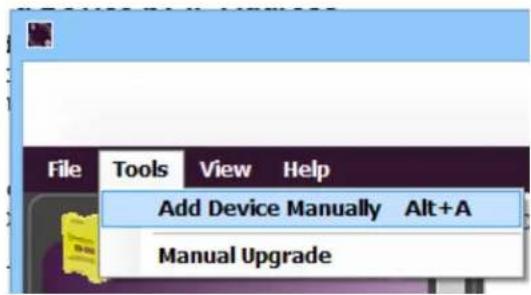
Select the 'Add device by MAC address' radio button then enter the MAC address of your device.
Add Device Manually - Step 1 of 2
×

There are two methods to add a device into Boost.IO Manager, either using the device's IP address or the device's MAC address.
Important Note:
If the device is on a different network or behind a firewall - like for example when accessing the device from the internet - port forwarding is required. Please contact your network administrator to setup port forwarding.

Add device by IP address
Device IP Address:

Device Port Number:


Add device by MAC address
Device MAC Address:
\~nter the "#\$ address of your device into the text box and click the 'Next' button.
Add Device Manually - Step 2 of 2
×

Important Note:
If the device is on a different network or behind a firewall port forwarding is required. Please enter the "forwarded port number" for each port of the device below, then press 'Add'.
If this is not required, just press 'Add' to accept the default values.
IP Address: 192.168.0.130
Open Device Web Page
Web Port Number: 80
ASCII Protocol Port:
9500
Add
Cancel
5.8 IP Addressing
The I+ address settings can be easily changed using Boost.IO Manager.
- Click on the device of which you want to change the settings.
- In the 'Device Info' section on the left hand side, click the 'Change' link next to the current I+ address.
- Click 'OK' to confirm that you do want to change the I+ address of your device

- Select the 'Assign Static I+ Address' radio button and enter an I+ Address, Subnet Mask and Gateway Address then click 'Apply'.

- The ED device will reboot itself and have the new I+ address once it has booted back up.
5.9 Rebooting Device
Note: Please ensure your device is not in operation before rebooting it to prevent data loss.
To reboot your device, firstly open Boost.IO Manager and select the device you wish to reboot.
On the left side of Boost.IO Manager under the 'Other Tasks' section, click 'Reboot Device'.
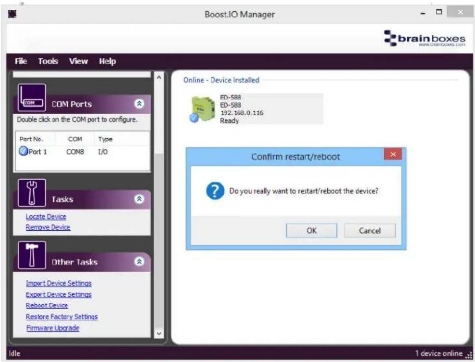
Confirm that you want to reboot your device.
The device will then reboot. Once the LED's on the device are green it is ready to use again.
5.10 Restoring Factory Settings
Note: Restoring the Factory Settings will erase any current settings that you have on your 9D device. Please ensure your device is not in operation before rebooting it to prevent data loss.
-
To restore the factory settings of your device, open Boost.IO Manager and select the device which you want to restore.
-
On the left side of Boost.IO Manager, under the 'Other Tasks' section, click the 'Restore Factory Settings' link.
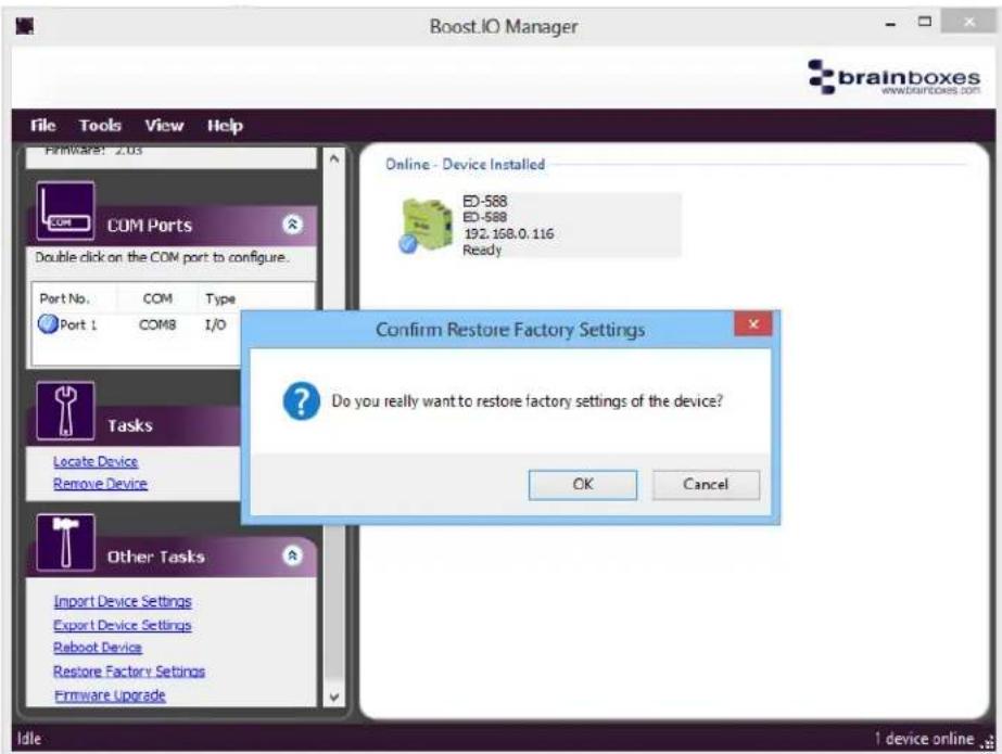
-
Confirm that you want to restore factory settings of the ED device.
-
The device will be rebooted and the factory settings will be restored.
5.11 Firmware Upgrade
Note: [efore upgrading your firmware5 please ensure your device is not in operation.
Open Boost.IO Manager and select your device in the window.
On the left side of Boost.IO Manager, under the 'Other Tasks' section, click the 'Firmware Upgrade' link.
hen the message box appears confirm that you have selected the correct device. If you wish to restore the device to default settings click the tick option and then click 'Upgrade'. Otherwise just click 'Upgrade'

Navigate to the location that saved the new firmware efw file and open it.

The \~@ device will be upgraded with the firmware file you selected and then will reboot.

\$lick ""K" when the upgrade success dialog box appears.
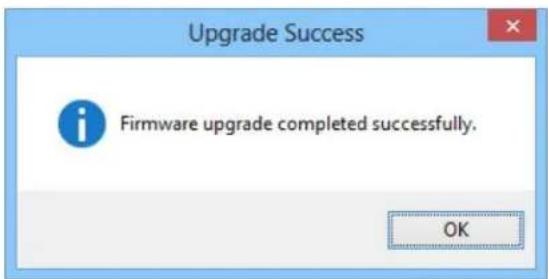
5.12 Proxy Server Settings
If you have a proxy server enabled on your +C this will restrict access to the web page interface. =ou may need to add the ED device to the +roxy Server's exceptions list. If you need help doing this contact your network administrator.
5.13 Device Swapping
In the unlikely event of a device failing, it can be easily replaced by swapping it with a device which has the same I+ address. This is particularly useful when using a large number of ED devices together which have already been installed and setup and are already communicating with peripherals. The faulty device can be replaced without having to set up and install a new device. To set the device to the same I+ address use the web page interface or Boost.IO to set the I+ address to the static address of the device you are replacing.
5.14 Adding a Remote Device Using Boost.IO
- To access the device through Boost.IO go to Tools and then click 'Add Device Manually'.
- Enter the public I+ address of your router into the Device I+ Address field, and the port forwarding number into the Device +ort Number field.
- Click the 'Next' button.


- Enter the port forwarding number for +ort 1 and then click the 'Add' button. The device will then appear in the Boost.IO manager window. It can then be installed and used as if it were on a local network.
5.15 Remote Access
The Remote access feature of the ED devices allows access to the device over the internet or from a different network. The device can be accessed either through the webpage interface, or through Boost.IO Manager. To access the ED device remotely, you will need the I+ address of the router and have port forwarding set up on your router for the device and the ports on your device. If you need assistance setting up port forwarding on your network, contact your network administrator.
Once you have the I+ address and port forwarding numbers of the device and the ports, you can either access the device through the webpage or add the device manually using Boost.IO Manager.
The ED devices store their settings in one place, inside the device. >hen accessing the device either from the web configuration pages or using Boost.IO Manager, it will get and set the settings inside the device itself. Therefore, if Boost.IO Manager is closed and a setting is updated using the web configuration pages, Boost.IO won't know that any settings have changed until it is opened. >hen the application opens, it will automatically get the settings of any installed devices.
6 Web Configuration Pages
6.1 Introduction
The web configuration pages for the ED device allow you to configure all the settings on the device and view the status of the device. To access the web configuration pages, type the I+ address of the device into a web browser. To find the I+ address of your device, see section 6.3 Finding and Installing an ED Device.
In the top right corner of every page there will be a box that displays information about your device. It will show you the model, firmware version, MAC address and how long the device has been powered on for.
Note: >e recommend that you use Internet Explorer Ωersion 7 and above
6.2 Home page
The Home page is the default page that loads when you enter the I+ address of the device into a web browser. This page mainly displays information about the device and a visual display of the states of the input and output/relay lines.

Device Information
Under the Device Information section is a text box which shows the current device name. This is the name that you can use to identify the device on your network. By default the device name is set to the product name but this can be changed by typing the name you would like into the text box and clicking 'Update'.
hen the Locate button is pressed, all the LED's on the front of the device will start flashing for 10 seconds. If you have a number of devices next to each other on a DIN rail, you may not be able to see the sticker on the side to identify the devices. Using the Locate button will allow you to clearly see which device you are configuring on the DIN rail.
Below this is the C+U temperature and voltages of the power supplies. The temperature will be displayed in green unless the C+U is getting hotter than it should in which case the temperature will be displayed in red.
Also, displayed is the state of both power inputs, in A and in B. The state will either be on or off, depending on whether they have power or not.
]urrent Protocol
The Current +rotocol section displays the state of the digital inputs and outputs. The digital input lines have three states that they can be in: on, off or overload. The digital output lines have 5 states, either high or low. These states are represented by the diagrams in the legends.
Current Protocol
![Brainboxes ED-004 - ]urrent Protocol - 1](/content/2026/05/964448/images/46499fb11daddaad986a0ef06f8d0c983cbcb436d1c4b35c55aa61b3ffc9a269.jpg)
flowchart
graph TD
    A["Digital Output (8): DOut 0"] --> B["ON (1)"]
    C["Digital Output (8): DOut 1"] --> D["OFF (0)"]
    E["Digital Output (8): DOut 2"] --> F["Overload"]
    G["Digital Output (8): DOut 3"] --> H["High (0)"]
    I["Digital Output (8): DOut 4"] --> J["Low (1)"]
    K["Digital Output (8): DOut 5"] --> L["High (0)"]
    M["Digital Output (8): DOut 6"] --> N["Overload"]
    O["Digital Output (8): DOut 7"] --> P["High (0)"]
    Q["Digital Input (8): Din 0"] --> R["High (0)"]
    S["Digital Input (8): Din 1"] --> T["High (0)"]
    U["Digital Input (8): Din 2"] --> V["High (0)"]
    W["Digital Input (8): Din 3"] --> X["High (0)"]
    Y["Digital Input (8): Din 4"] --> Z["High (0)"]
    AA["Digital Input (8): Din 5"] --> AB["High (0)"]
    AC["Digital Input (8): Din 6"] --> AC["High (0)"]
    AD["Digital Input (8): Din 7"] --> AE["High (0)"]
]onnections
The Connections tab displays information about any active connections to the device. The number of connections currently being made to the device will be displayed. The table will display more information about any devices connecting to the ED device.

Also, when a connection is made there will be a warning at the top of every page. >hen changing some of the settings, the device is required to be restarted for the settings to be applied and the ED device cannot be restarted while a connection is being made to it.
![Brainboxes ED-004 - ]onnections - 2](/content/2026/05/964448/images/1c760c50231b5e3395ca7f23d442da35bdf8ba17bece41ef03efb044cfcb3147.jpg)
There is an active connection to the device. Close all connections before changing any
Protocol Statistics
The +protocol Statistics tab will display information about the protocol commands that have been sent to the device since it was powered on, including a history of all the commands sent and the response of each command.
![Connections Protocol Statistics Device IP Settings Received: 1 Invalid Payload: 0 Success: 1 Invalid Length: 0 Responded: 1 Invalid Checksum: 0 Errors: 0 Invalid Address: 0 Route To Gateway: 0 Invalid Format: 0 Trace History: [00236AA0]CMD: $01M. [00236AA0]RES: I01ED-588. [00236AA0]Status: SUCCESS](/content/2026/05/964448/images/6d238f1266255ac9631b547526684cdbf8686dd66114bc57899c01614cb97007.jpg)
Device IP Settings
Under the Device I+ Settings tab there is information about the device's network settings. These settings can be changed on the Network page. See section 6.3 Network page.
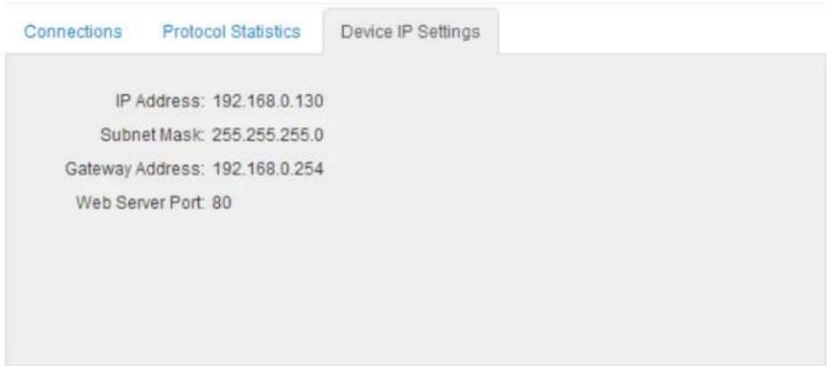
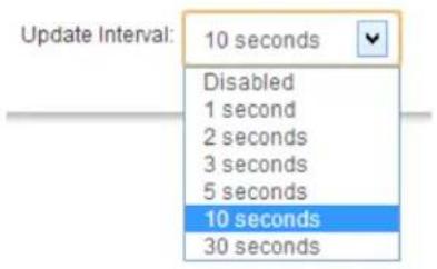
Update Interval
The Update Interval dropdown box controls how often the device information on the Home page will be refreshed. For example, if set to 5 seconds, the webpage will update all the temperature and voltage information, IO lines states, current connections, protocol statistics and device I+ settings automatically, every 5 seconds. If set to 'Disabled', the webpage will not update these settings and you will have to refresh the page manually.
6.3 Network page
The Network page allows you to configure all of the network settings of the ED device.
Network IP \*address
Please consult the Network Administrator before changing any settings.
Network IP Address
Web Server/UPnP
Obtain IP Address Automatically (Use DHCP)
○ Assign Static IP Address (Recommended)

Save
Cancel Changes
In the Network I+ Address tab you can select whether the device is using DHC+ or a static I+ address which you specify. By default the ED device is set to use DHC+ to obtain an I+ address automatically. If there is no DHC+ server present, after 60 seconds the device will switch to a static I+ address of 192.168.127.254.
Web Server7UPnP
Please consult the Network Administrator before changing any settings.

Under the >eb Server/U+n+ tab you can change the >eb Server +ort number and also turn U+n+ on or off. The default >eb Server +ort number is 80.
6.4 Serial Port page
The serial port page (available on some models) allows you to configure all the serial settings on the serial port on the device.
Serial Port 1
Port Status: Connected
Port Type: RS232
Default Serial Port Settings
√ Always use these settings (Ignore settings from application)

Parity: None
Flow Control: None


Protocol Settings
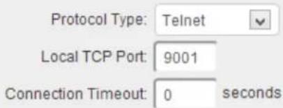
Note: Connection timeout will not be used if set to '0'.
Save
Cancel Changes
\*Iways Use These Settings
If the tick box "Always use these settings" is ticked then the serial port will communicate using the baud rate, data bits, parity, stop bits and flow control set in this section regardless of what settings the application is using. For example, this will allow you to force baud rates that your application does not allow you to select. This can be useful for interfacing to equipment which uses higher baud rates or unusual baud rates which your application does not support.
Protocol Type
If you are using the Brainboxes >indows driver to create a COM port then the driver will use Telnet regardless of the protocol setting set on the webpage.
RA> TC+: Data sent over the network is the same as the data sent over the serial link. Any configuration of the serial port settings will need to be set via the web page.
Telnet: This is based on the RFC2217 standard which lets the serial ports settings be configured dynamically. Data is then encapsulated over serial link
Local T]P Port
This configures which TC+ port the serial port of the ED device will use.
]onnection Timeout
The Connection Timeout is set to 0 by default. If it is set to anything other than 0, the connection to the port will be disconnected automatically after being idle (i.e. no data is being received or sent to and from the port) for the specified time. The LED for the port will go off at this point. If the Connection Timeout setting is 0, the port will need to be disconnected manually by the user.
6.5 Protocol page
The protocol page has all of the ASCII settings and serial gateway settings.

\*S]II Protocol Settings
Device \*address
The device address is a hexadecimal value which specifies the target device. If an ASCII command is being sent to a specific device, this address is used to specify which device the command is sent to. Also, any responses will contain a device address to indicate which device sent the response.
The number entered into the text box should be a decimal number between 1 and 255. Any decimal numbers entered will have their Hex value displayed to the right of the text box.
T]P Port
The TC+ port is the network port that is used to connect to the device at the I+ address that it's using. The default port number is 9500.
Idle Timeout
hen the idle timeout is set, if there is no communication to the device for the specified period of time, the connection will be closed. The default idle connection is 0, meaning the connection will never be dropped automatically.
]ounter Update Direction
The counter update direction can either be set to falling edge or rising edge using the drop down box. If the Update Direction is set to 'Falling Edge', the counter will be incremented every time the signal goes from high to low. If the Update Direction is set to 'Rising Edge' the counter will be incremented every time the signal goes from low to high. By default the Counter Update Direction is set to Falling Edge.

]ounter Mode
The Counter mode box allows you set the counter mode to either a 16-bit Counter or 32-bit Counter. A 16-bit counter will count from 0 to 65535 and a 32-bit counter will count from 0 to 4294967295.

]hecksum
The purpose of the checksum is to help the +C and devices detect the communication errors that have corrupted the command strings. >hen the checksum is enabled all commands from the +C to the devices and all responses from the devices must contain a valid checksum otherwise the data is discarded. >hen the checksum is enabled, commands sent without a valid checksum will be ignored by the devices and the device will not respond to the host +C. By default, the checksum is disabled.

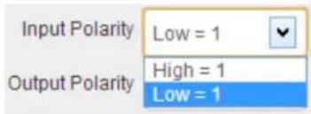
Input Polarity
The input polarity drop down box has 2 options. The first and default is 'High = 1'. >hen this option is selected, if a High voltage is applied to the input line then this will be displayed a 1. If there is no voltage applied to the input line, this will be Low and the input will be displayed as 0.
The second option is 'Low = 1'. If this is selected, when a High voltage is applied to the input line, then this will be displayed as 0. >hen no voltage is applied to the input line then 1 will be displayed.
Output Polarity
In the Output Polarity drop down box there are 2 options, '1 = ON' or '0 = ON'. >hen '1 = ON' is set, if there is a voltage on the output line, then the digital output will be 1. If there is no voltage being sent out then the digital output will be. >hen '0 = ON' is selected, when there is a voltage on the line the digital output will be 1. >hen there is no voltage on the output line then the digital output will be 0
For example, when the output polarity is set to '1 = ON' in the combo box...

...the Digital Output diagrams on the home page will display the 'OFF (0)' symbol when there is no voltage on the input lines.

Serial 'ateway
The Serial Gateway feature (available on ED-5XX models) turns the ED device into a serial gateway which allows it to send the commands out the gateway port to another ASCII protocol compatible device such as NuDAM, eDAM and ADAM modules. The gateway port uses half duplex RS485 with 8 data bits, no parity and 1 stop bit.
[aud Rate
The baud rate of the Serial Gateway can be changed using the drop down box. The default baud rate is 9600.

]ommand Timeout
The Command Timeout option determines how long the ED device will wait for a response from the Serial Gateway once a command has been sent. If, after the specified time no response has been received through the gateway port then the ED device will stop waiting for a response. If a response does come in after the timeout value, the response will be discarded. The default timeout is 500 milliseconds.
Command Timeout 200 ms
6.6 Console page
The Console +age contains the console window which allows ASCII commands to be sent straight to the device and be executed immediately. The response of the command is displayed in the console window in green. This is the simplest way to send ASCII commands to the ED device to either set or read settings.
Terminal Console
To communicate with the device, please enter any valid ASCII command. Please click here to view a list of ASCII Protocol commands.

Note: Please type 'clear' to clear the console screen.
Also on the Console page is a link to a web view of all the ASCII protocol commands that can be sent to the device and a description of what each command does.
ASCII Command Summary
| Command | Response | Description |
| MAMINTTCCFF | MA | Set Module Configuration |
| a** | No Response | Check this is R** command |
| RAN80DD RAMACDD | * | Check this is RAN80 and RAN8A commands set output value of lower 8 channels |
| RAM80D | * | Check this is RAM80 command, set output value of upper 8 channels |
| RA1cDD RAMACDD | * | Sets a single digital output channel of the lower eight channels |
| RAM80D | * | Sets a single digital output channel of the upper eight channels |
| RAN | MA(Data) | Reads the digital input counter of channel N |
| SAA2 | RAMINTTCCFF | Read the module configuration |
| SAA4 | R(Data) | Reads the synchronized data that was retrieved by the last R** commands |
| SAA5 | ISC(Data) | Reads the reset status of the module. |
| SAA6 | RAS | Reads the status of the digital input output channel |
| SAA9 | Reads the status of the digital output Service line value on all output channel | |
| SAAC | MA | Clears the status of matched digital input channels |
| SAACH | MA | Clears the digital input counter of channel N |
| SAAF | RA(Data) | Reads the firmware version of a module |
| SAALS | I(Data) | Reads the status of the matched digital input channels |

6.7 IO Lines page
The IO Lines page lists all the output lines on the device and allows you to set the +ower-On Ωalue, Safe Ωalue and Quick Stop Ωalue for each of the output lines.
Note) The Quick Stop feature has not been designed or qualified as an \~mergency Stop device and must not be used as part of a safety critical control system
Power8On Value
The +ower-On Ωalue drop down boxes determine what state the output lines will go to every time the device is powered on. *y default, all of the output lines will be set low when the device is powered on.
For example, if the drop down boxes are set like below...
| Line | Mode | Power-On Value | Safe Value | Quick Stop Value |
| DOut 0 | Digital Output | ON | OFF | OFF |
| DOut 1 | Digital Output | OFF | OFF | OFF |
| DOut 2 | Digital Output | ON | OFF | OFF |
| DOut 3 | Digital Output | OFF | OFF | OFF |
| DOut 4 | Digital Output | ON | OFF | OFF |
| DOut 5 | Digital Output | OFF | OFF | OFF |
| DOut 6 | Digital Output | ON | OFF | OFF |
| DOut 7 | Digital Output | OFF | OFF | OFF |
...when the device is powered on with these settings, the output lines of the device will be...

Safe Value
'he Safe Ωalue drop down boxes set the state that the output lines will go when the device goes into a >atchdog state. 'his ensures that even if there is a problem with the communication to the device, the output lines will always revert to a safe, known state.
hen the safe value is set like the pattern below...
| Line | Mode | Power-On Value | Safe Value | Quick Stop Value | |||
| DOut 0 | Digital Output | OFF | √ | OFF | √ | OFF | √ |
| DOut 1 | Digital Output | OFF | √ | OFF | √ | OFF | √ |
| DOut 2 | Digital Output | OFF | √ | OFF | √ | OFF | √ |
| DOut 3 | Digital Output | OFF | √ | OFF | √ | OFF | √ |
| DOut 4 | Digital Output | OFF | √ | ON | √ | OFF | √ |
| DOut 5 | Digital Output | OFF | √ | ON | √ | OFF | √ |
| DOut 6 | Digital Output | OFF | √ | ON | √ | OFF | √ |
| DOut 7 | Digital Output | OFF | √ | ON | √ | OFF | √ |
...and the device goes into a >atchdog state for whatever reason, there will be a message at the top of every configuration page warning about the state.

Iso, the output lines will be set to the state which has been set on the I" Lines page.

Quick Stop Value
hen the 'uick Stop Ωalue is enabled, all the output lines will go to a user specified known state when the user programmed input transitions to a preconfigured high or low state.
To set the Quick Stop Ωalue, the first thing that needs to be selected is the input line which is going to wait for the high or low signal.

Once the input line is selected, another drop down box will appear which allows you to select when the output line state is set. This could be on the falling edge, when the input line goes from high to low, or the rising edge, when the input line goes from low to high.

Once this has been selected, set the digital output line pattern needs to be set.
As an example, from the settings on the page below, when the signal of the first input line (Din 0) goes from high to low, the first four outputs, DOut 0, DOut 1, DOut, 5 and DOut 3 will be set high and the second four outputs will be set low.
| Line | Mode | Power-On Value | Safe Value | Quick Stop Value | |||
| DOut 0 | Digital Output | OFF | √ | OFF | √ | OFF | √ |
| DOut 1 | Digital Output | OFF | √ | OFF | √ | OFF | √ |
| DOut 2 | Digital Output | OFF | √ | OFF | √ | OFF | √ |
| DOut 3 | Digital Output | OFF | √ | OFF | √ | OFF | √ |
| DOut 4 | Digital Output | OFF | √ | ON | √ | ON | √ |
| DOut 5 | Digital Output | OFF | √ | ON | √ | ON | √ |
| DOut 6 | Digital Output | OFF | √ | ON | √ | ON | √ |
| DOut 7 | Digital Output | OFF | √ | ON | √ | ON | √ |
Please Select Quick Stop IO Line : DIn 0 when Falling Edge
6.8 Device Management page
The Device Management page has 2 options. The first is to restart your device and the second to restore the factory default settings of the device.
Device Management
Click to restart the device
Restart Device
Click to restore the factory settings
Clicking the 'Restart Device' button will power cycle the device. In order to restart the device, there must be no connections being made to it. If there is a connection being made to the device, a warning message will be displayed asking you to close the connection.
Clicking the 'Restore Factory Default' button will revert all the settings on the device back to their factory default. Just like restarting the device, in order to restore the factory settings, there must be no connection to the device active. For a list of the factory settings of the device please see section 7.8 Factory Default Settings.
6.9 Factory Default Settings
| Network Settings | |
| Network IP Address DHCP Mode | |
| >eb Server Port 9500 | |
| *S]II Protocol Settings | |
| Device Address 01 | |
| TCP Port 9500 | |
| Idle Timeout 0 | |
| Counter Update Direction | Falling Edge |
| Checksum Disabled | |
| Input Polarity High = 1 | |
| Output Polarity | 1 = ON |
| Serial 'ateway Settings | |
| Baud Rate 9600 | |
| Command Timeout | 200 ms |
7 Configuration Tables
7.1 Baud Rate Settings (BB)
| Code: 03 04 | 05 06 07 | 08 09 0A | ||||||
| Baud Rate: | 1200 | 2400 | 4800 | 9600 | 19200 | 38400 | 57600 | 115200 |
7.2 Data Format Settings (FF)
| 7 | 6 | 5 | 4 | 3 | 2 | 1 | 0 |
| CU | CS | CM | Reserved | ||||
CS: Checksum Setting
0: Disabled
1: Enabled
CU: Counter Update
0: Falling edge in the input signal
1: Rising edge in the input signal
CM: Counter Mode
0: 16 bit Counter
1: 32 bit Counter
Note: The counter value will be preserved until it is either cleared or restored to factory settings. The counter will be preserved when the device is rebooted or powered off and on.
7.3 Digital Input/Output Data Characters Format
Some of the ASCII commands require data to be sent to set the output lines. Other ASCII commands will return the status of the input and output lines. The status of the output and input lines in the commands and responses will be in a 2 digit hexadecimal format.
For example, the response from the @AA command for the ED-588 is: >(first 2 hex digits)(second 2 hex digits)
The table below details which input/output lines these hexadecimal digits correspond to for your device.
| Device | First 2 hexadecimal digits | Second 2 hexadecimal digits | ||
| ED-588 | DOut 7 - DOut 0 | 00-FF | DIn 7 – DIn 0 | 00-FF |
| ED-516 | DIn 15 – DIn 8 | 00-FF | DIn 7 – DIn 0 | 00-FF |
| ED-527 | DOut 15 – DOut 8 | 00-FF | DOut 7 – DIn 0 | 00-FF |
| ED-538 | RL 0 – RL 3 | 00-0F | DIn 7 – DIn 0 | 00-FF |
| ED-038 | RL 0 – RL 2 | 00-07 | Din 2 – Din 0 | 00-07 |
| ED-008 | DOut 7 - DOut 0 | 00-FF | DIn 7 – DIn 0 | 00-FF |
| ED-204 | DOut 3 – Dout 0 | 00-0F | DIn 3 – DIn 0 | 00-0F |
| ED-004 | DOut 3 – Dout 0 | 00-0F | DIn 3 – DIn 0 | 00-0F |
8 ASCII Protocol
8.1 Introduction
The ASCII protocol is a query-response or a question and answer communication protocol in which a host +C uses ASCII characters to send commands to a device and then receives responses back from that device. The ASCII command set is used to configure devices, send data to devices and to read data and status information back from devices
Command Format
The command string is made up of several different parts. For example, the command #AA00DD can be broken down into as many as 6 separate parts.
| # | AA | 00 | (Data) | [CS] | (CR) |
| Delimiter | Address | Command | Data* | Checksum** | Carriage Return |
* Only applicable for commands setting digital outputs.
** Optional parameter for the command.
Every ASCII command sequence is a series of ASCII characters starting with a prefix delimiter and terminating with a carriage return character. All of the ASCII characters used are easily entered from a +C keyboard and every ASCII command is terminated with a Carriage Return character; hex 0D, denoted by (CR) All commands being sent to the device must be in uppercase characters.
Prefix or Delimiter: Each ASCII command starts with a single character command prefix or delimiter. The prefix will be one of the following five characters:-
| # the hash or pound sign, ASCII value hex 0x23 | |
| % the percentage sign, ASCII value hex 0x25 | |
| $ the dollar sign, ASCII value hex 0x24 | |
| @ the at sign, ASCII value 0x40 | |
| ~ | the tilde or approx. sign, ASCII value hex 0x7E |
These prefix signs cannot be used interchangeably but are particular to the command string which follows.
Address: The ASCII protocol was first introduced in the 1980s by Analog Devices with its RS485 Half Duplex connected 6B Series modules and digital I/O boards and has been adopted and adapted by many other companies since. It is the de-facto communication protocol on the widely used RS485 Half Duplex connected ADAM/NuDam/eDAM modules. A very wide range of +C based data acquisition packages have support for this command protocol communicating over +C COM port. The Brainboxes ED-xxx range of devices are completely backwards compatible with these devices.
Since it was initially developed for an RS485 bus system containing many devices, each ASCII command must include the address of the particular device the command is directed to. The address is a two character field giving the hexadecimal address of the device (00-FF). The default address is 01. The address field is written as AA in the examples that follow.
A few commands do not have an address as these are broadcast commands that go to all the devices. Here the address field AA is replaced by the wildcard two star signs **. Two such examples are #** and \~**.
Command: The command field contains the command that you want to send to the device. The next section (Command List) gives a detailed description of how to use each command and what the commands do.
Data: The data being sent to the device which is required in the command. Depending on the command this data is in different formats.
Checksum: An optional two character checksum denoted [CS] can be included immediately before the terminating (CR). The purpose of the checksum is to help the PC and devices detect the communication errors that have corrupted the command strings. When the checksum is enabled all commands from the PC to the devices and all responses from the devices must contain a valid checksum otherwise the data is discarded. When the checksum is enabled, commands sent without a valid checksum will be ignored by the devices and the device will not respond to the host PC. By default the checksum is turned off. To turn checksum on, you must configure the device via its webpage using a browser.
In the following sections of this chapter, those parts of the command string in bold and underlined are parameters that the user must enter. Those parts of the command string in normal text are to be used literally in the command without replacement by the user.
Additionally, any parts of the command string that are in square brackets are optional. The checksum is an example of this as it is only required when the checksum is enabled in the firmware of the device.
9example Commands: Assuming that the checksum has not been turned on by the user, the simplest command is:
@AA(CR)
This command reads the status of the digital input port. Assuming the ED devices address is 01, that is AA=01, then the command the user would issue would be:
@01(CR)
A typical response from the device would be:
01FA(CR)
Response Format
The response received from the device will depend on the ASCII command that has been sent. The response for each command is detailed in the Command List Section.
| ! | AA | (Data) | [CS] | (CR) |
| Delimiter Address Data* Checksum** Carriage Return | ||||
* Only applicable for certain commands that return data.
** Optional parameter for the command.
Prefix or Delimiter: Each ASCII response starts with a single character prefix or delimiter. The prefix will be one of the following three characters:-
| > | Greater than sign, ASCII value hex 0x3E |
| ! | Exclamation sign, ASCII value hex 0x21 |
| ? | Question mark sign, ASCII 0x3F |
Address: The address is a two character field giving the hexadecimal address of the device (00-FF). The default address is 01. The address field is written as AA in the examples that follow.
Data: The data being sent from the device in response to the command sent.
Checksum: Optional 2 character checksum.
8.2 Command List
| ]ommand | Response | Description | Supported Devices |
| %AANNTTCCFF | !AA Set Device Configuration All Devices | ||
| #** | No Response Syncronized Sampling All Devices | ||
| #AA00DD | > Set Digital Output of Lower 8 Channels Devices with Outputs | ||
| #AA0ADD | > Set Digital Output of Lower 8 Channels Devices with Outputs | ||
| #AA0BDD | > Set Digital Output of Upper 8 Channels Devices with Outputs | ||
| #AA1cDD | > Set a Single Digital Output of Lower 8 Channels | Devices with Outputs | |
| #AAAcDD | > Set a Single Digital Output of Lower 8 channels | Devices with Outputs | |
| #AABcDD | > Set a Single Digital Output of Upper 8 Channels | Devices with more than 8 Outputs | |
| #AAN | !AA(Data) | Read Digital Input Counter | Devices with Inputs |
| AA2 | !AANNTTCCFF | Read Device Configuration | All Devices |
| AA4 | !S(Data) | Read Synchronized Data | All Devices |
| AA5 | !AAS | Read Reset Status | All Devices |
| AA6 | !(Data) | Read Digital I/O Status | All Devices |
| AAC | !AA Clear Latched Digital Input Devices with Inputs | ||
| AACN | !AA Clear Digital Input Counter Devices with Inputs | ||
| AAF | !AA(Data) | Read Firmware Qersion | All Devices |
| AALS | !(Data) | Read Latched Digital Input | Devices with Inputs |
| AAM | !AA(Data) | Read Device Name | All Devices |
| AAM0 | !AA(Data) | Read Device Model | All Devices |
| AAM1 | !AA(Data) | Read Device Location | All Devices |
| AAS1 | !AA Restore Factory Defaults All Devices | ||
| $AARS | No Response Reset the module to power-on state All Devices | ||
| @AA | >(Data) | Read Digital I/O Status | All Devices |
| @AA(Data) | > Set Digital Output Devices with Outputs | ||
| ~AAO(Name) | !AA Set Device Name All Devices | ||
| ~** | No Response Host OK All Devices | ||
| ~AA0 | !AASS | Read Watchdog Timeout Status | All Devices |
| ~AA1 | !AA Reset Watchdog Timeout Status All Devices | ||
| ~AA2 | !AAΩΩ | Read Watchdog Timeout Settings | All Devices |
| ~AA3EΩΩ | !AA Set Watchdog Timeout Ωalue All Devices | ||
| ~AA4Ω | !AA(Data) | Read Power On/Safe Ωalue | Devices with Outputs |
| ~AA5Ω | !AA Set Power On/Safe Ωalue Devices with Outputs | ||
| ~AAL | !AASS | Set Device Location | All Devices |
8.3 %AANNTTCCFF
Description:
Set the device configuration.
Command Syntax:
| %**NNTTCCFF [CS](CR) | |
| % | Delimiter character |
| ** | Address of the device to be configured in hexadecimal format ( 00 to FF) |
| NN | New device address in hexadecimal format (00 to FF) |
| TT | Type code, should be 40 for DIO module |
| CC | New Baud Rate code. (SeeBaud Rate Settings) |
| FF | Used to set the counter update direction and checksum(SeeData Format Settings) |
| [CS] | Checksum |
| (CR) | Carriage Return |
Response:
Ωalid Command: !**CS
Invalid Command: ?**CS
| ! | Delimiter for a valid command |
| ? | Delimiter for an invalid command |
| ** | Address of the device in hexadecimal format (00 to FF) |
| [CS] | Checksum |
| (CR) | Carriage Return |
Examples:
Change the device address from 01 to 02. The device returns a valid response.
Command: %0102400600(CR)
Response: !02(CR)
Change the Baud Rate of device 01 to 115200. Device returns a valid response.
Command: %0101400A00(CR)
Response: !01(CR)
Change the Baud Rate of device 01 to 115200. Device returns invalid command because the baud rate code is incorrect.
Command: %010140FF00(CR)
Response: ?01(CR)
Note: Any change to the address and counter update direction take effect once the command has been received. Changes to the Baud Rate and checksum settings take effect the next time the device is restarted.
8.4 #\*\*
Description:
Allows the device to read and store data for later retrieval.
Command Syntax:
| #**[CS](CR) | |
| # | Delimiter character |
| ** | Synchronized Sampling Command |
| [CS] | Checksum |
| (CR) | Carriage Return |
Response:
There is no response for this command. To access the data, use the command \$AA4.
Examples:
Send synchronized sampling command.
Command: #**(CR)
No Response
8.5 #AA00DD
Description:
Sets the digital output value of the lower eight channels.
Command Syntax:
| #** 0ODD[CS](CR) | |
| # | Delimiter character |
| ** | Address of the device to be configured in hexadecimal format (00 to FF) |
| 00 | Command to set the digital output value of the lower 8 channels |
| DD | Two digit hexadecimal value. Bit 0 corresponds to DOut 0, bit 1 corresponds to DOut 1, etc. If the bit is 1, the digital output channel will be on, if the bit is 0, the digital output channel will be off. |
| [CS] | Checksum |
| (CR) | Carriage Return |
Response:
Ωalid Command: >CS
Invalid Command: ?CS
Ignored Command:

| > | Delimiter for a valid command |
| ? | Delimiter for an invalid command |
| ! | Delimiter for an ignored command |
| [CS] | Checksum |
| (CR) | Carriage Return |
Examples:
Set DOut 0, DOut 1, DOut 2, DOut 3 to on, and DOut 4, DOut 5, DOut 6, DOut 7 to off and device returns a valid response.
Command: #01000F(CR)
Response: >(CR)
Note: This command is only applicable on devices with digital output channels.
8.6 #AA0ADD
Description:
Sets the digital output value of the lower eight channels.
Command Syntax:
| #** 0A DD[CS](CR) | |
| # | Delimiter character |
| ** | Address of the device to be configured in hexadecimal format (00 to FF) |
| OA | Command to set the digital output value of the lower 8 channels |
| DD | Two digit hexadecimal value. Bit 0 corresponds to DOut 0, bit 1 corresponds to DOut 1, etc. If the bit is 1, the digital output channel will be on, if the bit is 0, the digital output channel will be off. |
| [CS] | Checksum |
| (CR) | Carriage Return |
Response:
Ωalid Command: >CS
Invalid Command: ?CS
Ignored Command:
| > | Delimiter for a valid command |
| ? | Delimiter for an invalid command |
| ! | Delimiter for an ignored command |
| [CS] | Checksum |
| (CR) | Carriage Return |
Examples:
Set DOut 0, DOut 1, DOut 2, DOut 3 to on, and DOut 4, DOut 5, DOut 6, DOut 7 to off and device returns a valid response.
Command: #010A0F(CR)
Response: >(CR)
Note: This command is only applicable on devices with digital output channels.
8.7 #AA0BDD
Description:
Sets the digital output value of the upper eight channels.
Command Syntax:
| #**OBDD[CS](CR) | |
| # | Delimiter character |
| ** | Address of the device to be configured in hexadecimal format (00 to FF) |
| OB | Command to set the digital output value of the upper 8 channels |
| DD | Two digit hexadecimal value. Bit 0 corresponds to DOut 0, bit 1 corresponds to DOut 1, etc. If the bit is 1, the digital output channel will be on, if the bit is 0, the digital output channel will be off. |
| [CS] | Checksum |
| (CR) | Carriage Return |
Response:
Ωalid Command: >CS
Invalid Command: ?CS
Ignored Command:
| > | Delimiter for a valid command |
| ? | Delimiter for an invalid command |
| ! | Delimiter for an ignored command |
| [CS] | Checksum |
| (CR) | Carriage Return |
Examples:
Set DOut 8, DOut 9, DOut 10, DOut 11 to on, and DOut 12, DOut 13, DOut 14, DOut 15 to off and device returns a valid response.
Command: #010B0F(CR)
Response: >(CR)
Note: This command is only applicable on devices with digital output channels.
8.8 #AA1cDD
Description:
Sets the specified digital output channel of the lower eight channels.
Command Syntax:
| #**1cDD[CS](CR) | |
| # | Delimiter character |
| ** | Address of the device to be configured in hexadecimal format (00 to FF) |
| 1 | Command to set a single digital output of the lower 8 channels |
| Specifies the digital output channel to be set (0-7) | |
| 00: set the digital output channel to off01: set the digital output channel to on | |
| [CS] | Checksum |
| (CR) | Carriage Return |
Response:
Ωalid Command: >CS
Invalid Command: ?CS
Ignored Command:
| > | Delimiter for a valid command |
| ? | Delimiter for an invalid command |
| ! | Delimiter for an ignored command |
| [CS] | Checksum |
| (CR) | Carriage Return |
Examples:
Set DOut 1, to on and device returns a valid response.
Command: #011101(CR)
Response: >(CR)
Note: This command is only applicable for the devices with digital output channels.
8.9 #AAAcDD
Description:
Sets the specified digital output channel from the lower eight channels.
Command Syntax:
| #** AcDD[CS](CR) | |
| # | Delimiter character |
| ** | Address of the device to be configured in hexadecimal format (00 to FF) |
| A | Command to set a single digital output of the lower 8 channels |
| Specifies the digital output channel to be set (0-7) | |
| 00: set the digital output channel to off01: set the digital output channel to on | |
| [CS] | Checksum |
| (CR) | Carriage Return |
Response:
Ωalid Command: >CS
Invalid Command: ?CS
Ignored Command:
| > | Delimiter for a valid command |
| ? | Delimiter for an invalid command |
| ! | Delimiter for an ignored command |
| [CS] | Checksum |
| (CR) | Carriage Return |
Examples:
Set DOut 1, to on and device returns a valid response.
Command: #01A101(CR)
Response: >(CR)
Note: This command is only applicable for the devices with digital output channels.
8.10 #AABcDD
Description:
Sets the specified digital output channel from the upper eight channels.
Command Syntax:
| #** BcDD[CS](CR) | |
| # | Delimiter character |
| ** | Address of the device to be configured in hexadecimal format (00 to FF) |
| B | Command to set a single digital output of the upper 8 channels |
| c | Specifies the digital output channel to be set (0-7) where 0 stands for channel 8, 1 stands for channel 9 etc |
| DD | 00: set the digital output channel to off01: set the digital output channel to on |
| [CS] | Checksum |
| (CR) | Carriage Return |
Response:
Ωalid Command: >CS
Invalid Command: ?CS
Ignored Command:
| > | Delimiter for a valid command |
| ? | Delimiter for an invalid command |
| ! | Delimiter for an ignored command |
| [CS] | Checksum |
| (CR) | Carriage Return |
Examples:
Set DOut 11, to on and device returns a valid response.
Command: #01B301(CR)
Response: >(CR)
Note: This command is only applicable for the devices with 8 or more digital output channels.
8.11 #AAN
Description:
Reads the digital input counter value of specified channel.
Command Syntax:
| #**N[CS](CR) | |
| # | Delimiter character |
| ** | Address of the device to be configured in hexadecimal format (00 to FF) |
| Digital input channel to be read (0 to F) | |
| [CS] | Checksum |
| (CR) | Carriage Return |
Response:
Ωalid Command: !**DataCS
Invalid Command: ?**CS
| ! | Delimiter for a valid command |
| ? Delimiter for an invalid command | |
| ** | Address of the device in hexadecimal format (00 to FF) |
| Data | If the counter mode of the device is set to 16-bit, then the data will be a five digit decimal representing the digital input counter value. (00000 to 65535)If the counter mode is set to 32-bit, then the data will be a ten digit decimal representing the digital input counter value.(0000000000 to 4294967295) |
| [CS] Checksum | |
| (CR) Carriage Return | |
Examples:
Read counter value of digital input channel 3 and the returned value is 00274 as a five digit decimal value.
Command: #013(CR)
Response: !0100274(CR)
Read data from channel 9. An error is response is returned because channel 9 is an invalid channel.
Command: #019(CR)
Response: ?01(CR)
Note: This command is only applicable for the devices with digital input channels.
8.12 \$AA2
Description:
Reads device configuration.
Command Syntax:
| ** 2[CS](CR) | |
| Delimiter character | |
| ** | Address of the device to be configured in hexadecimal format (00 to FF) |
| 2 | Command to read the device configuration |
| [CS] | Checksum |
| (CR) | Carriage Return |
Response:
Ωalid Command: !**TTBBFFCS
Invalid Command: ?AACS
| ! | Delimiter for a valid command |
| ? | Delimiter for an invalid command |
| ** | Address of the device (00 to FF) |
| TT | Device Type (40 for DIO Devices) |
| BB | Baud Rate of the device (See Baud Rate Settings) |
| FF | Configuration value (See Data Format Settings) |
| [CS] | Checksum |
| (CR) | Carriage Return |
Examples:
Read the configuration of device 01.
Command: \$012(CR)
Response: !010400600(CR)
8.13 \$AA4
Description:
Reads the synchronized data retrieved from the last #** command.
Command Syntax:
| ** 4[CS](CR) | |
| Delimiter character | |
| ** | Address of the device to be configured in hexadecimal format (00 to FF) |
| 4 | Command to read the synchronized data from the device. |
| [CS] | Checksum |
| (CR) | Carriage Return |
Response:
Ωalid Command: !SDDDD00CS
Invalid Command: ?**CS
| ! | Delimiter for a valid command |
| ? | Delimiter for an invalid command |
| S | Status of synchronized data:1 = First read of data0 = Data has been at least once before |
| DDDD | Four digit hexadecimal value representing the status of the I/O lines. |
| 00 | Always 00 |
| [CS] | Checksum |
| (CR) | Carriage Return |
Examples:
Read synchronized data. Device returns the synchronized data and sets first byte to 1 to indicate this is the first time the synchronized data has been read. (Assumes the set synchronized data command has been sent)
Command: \$014(CR)
Response: !1000F00(CR)
Read synchronized data. Device returns synchronized data and sets status byte to 0 to indicate the data has been read before.
Command: \$014(CR)
Response: !0000F00(CR)
8.14 \$AA5
Description:
Read the reset status of the device.
Command Syntax:
| ** 5[CS](CR) | |
| Delimiter character | |
| ** | Address of the device to be configured in hexadecimal format (00 to FF) |
| 5 | Command to read the reset status of the device |
| [CS] | Checksum |
| (CR) | Carriage Return |
Response:
Ωalid Command: !**SCS
Invalid Command: ?**CS
| ! | Delimiter for a valid command |
| ? | Delimiter for an invalid command |
| ** | Address of the device (00 to FF) |
| S | Reset status of the device:1 = First time the command has been sent since device was powered on0 = Not the first time the command has been sent since the device was powered on |
| [CS] | Checksum |
| (CR) | Carriage Return |
Examples:
Read reset status of the device. Response shows it is the first time the device has received the \$AA5 command since it was powered on.
Command: \$015(CR)
Response: !011(CR)
Read reset status of the device. Response shows that the device has received the \$AA5 command while it's been powered on.
Command: \$015(CR)
Response: !010(CR)
8.15 \$AA6
Description:
Reads the digital input and digital output channel values.
Command Syntax:
| ** 6[CS](CR) | |
| Delimiter character | |
| ** | Address of the device to be configured in hexadecimal format (00 to FF) |
| 6 | Command to read the digital I/O channels |
| [CS] | Checksum |
| (CR) | Carriage Return |
Response:
Ωalid Command: !DDDD00CS
Invalid Command: ?**CS
| ! | Delimiter for a valid command |
| ? | Delimiter for an invalid command |
| DDDD | Four digit hexadecimal value representing the status of the I/O lines. |
| 00 | Always 00 |
| [CS] | Checksum |
| (CR) | Carriage Return |
Examples:
Reads the values of the digital input and digital output channels. Returns !FF0000 meaning that the all the output lines are high and all the input lines are low.
Command: \$016(CR)
Response: !FF0000(CR)
8.16 \$AAC
Description:
Clears the status of the latched digital input channels.
Command Syntax:
| ** C[CS](CR) | |
| $ | Delimiter character |
| ** | Address of the device to be configured in hexadecimal format (00 to FF) |
| C | Command to clear latched digital input |
| [CS] | Checksum |
| (CR) | Carriage Return |
Response:
Ωalid Command: !**CS
Invalid Command: ?**CS
| ! | Delimiter for a valid command |
| ? | Delimiter for an invalid command |
| ** | Address of the device which responded |
| [CS] | Checksum |
| (CR) | Carriage Return |
Examples:
Sends command to clear the status of the latched digital input channels. Returns a valid response.
Command: \$01C(CR)
Response: !01(CR)
Note: This command is only applicable on devices with digital input channels.
8.17 \$AACN
Description:
Clears the digital input counter of the specified channel.
Command Syntax:
| ** CN[CS](CR) | |
| Delimiter character | |
| ** | Address of the device to be configured in hexadecimal format (00 to FF) |
| C | Command to clear digital input counter |
| N | Channel to be cleared (0 to F) |
| [CS] | Checksum |
| (CR) | Carriage Return |
Response:
Ωalid Command: !**CS
Invalid Command: ?**CS
| ! | Delimiter for a valid command |
| ? | Delimiter for an invalid command |
| ** | Address of the device which responded |
| [CS] | Checksum |
| (CR) | Carriage Return |
Examples:
Sends command to clear the value of channel 3. Returns a valid response.
Command: \$01C3(CR)
Response: !01(CR)
Note: This command is only applicable on devices with digital input channels.
8.18 \$AAF
Description:
Reads the firmware version of the device.
Command Syntax:
| ** F[CS](CR) | |
| Delimiter character | |
| ** | Address of the device to be configured in hexadecimal format (00 to FF) |
| F | Command to read the firmware version |
| [CS] | Checksum |
| (CR) | Carriage Return |
Response:
Ωalid Command: !**(Data)CS
Invalid Command: ?**CS
| ! | Delimiter for a valid command |
| ? | Delimiter for an invalid command |
| ** | Address of the device which responded |
| (Data) | Firmware version of the responding device. |
| C©KSUM | Checksum |
| (CR) | Carriage Return |
Examples:
Reads the firmware version of the device and shows it as version 1.9.
Command: \$01F(CR)
Response: !011.9(CR)
8.19 \$AALS
Description:
Reads the status of the latched digital input channels.
Command Syntax:
| **LS[CS](CR) | |
| $ | Delimiter character |
| ** | Address of the device to be configured in hexadecimal format (00 to FF) |
| L | Command to read the latched status |
| S | Reads the latched status:0 = read low latched status1 = read high latched status |
| [CS] | Checksum |
| (CR) | Carriage Return |
Response:
Ωalid Command: !DDDD00CS
Invalid Command: ?**CS
| ! | Delimiter for a valid command |
| ? | Delimiter for an invalid command |
| ** | Module Address ID |
| DDDD | Status of latched digital input channels. |
| 00 | This value is always 00 |
| [CS] | Checksum |
| (CR) | Carriage Return |
Examples:
Reads the status of the low latched digital input. Command is valid and device returns 00FF
Command: \$01L0(CR)
Response: !00FF00(CR)
Note: This command is only available on devices with digital input channels.
8.20 \$AAM
Description:
Read the name of the device.
Command Syntax:
| ** M[CS](CR) | |
| Delimiter character | |
| ** | Address of the device to be configured in hexadecimal format (00 to FF) |
| M | Command to read the device's name |
| [CS] | Checksum |
| (CR) | Carriage Return |
Response:
Ωalid Command: !**(Data)CS
| ! | Delimiter for a valid command |
| ? | Delimiter for an invalid command |
| ** | Address of the responding device |
| (Data) | Name of the device |
| [CS] | Checksum |
| (CR) | Carriage Return |
Examples:
Reads the device name. Command sent to the ED-588 and a valid response is returned with the device's name, ED-588.
Command: \$01M(CR)
Response: !01ED-588(CR)
8.21 \$AAS1
Description:
Restores the device settings back to factory defaults
Any Digital Outputs on the device will be reset to O+EN (0)
Digital Input reset values are dependant on 2 properties:
-
hether the line is connected to an external device.
- If the input is not connected then it will float
- If the input is connected then it will be at the value set by the external device.
- N+N/+N+ jumper setting
- N+N jumper setting means the Inputs will float HIGH (1). This is the factory default.
○ +N+ jumper setting means the Inputs will float LO> (0)
Therefore a factory reset ED-588 which is disconnected from input lines, and with factory default jumper setting, will have its IO lines reset to: FF00 - inputs float HIGH (1), outputs open (0)
Note: After this device has responded, it will reboot and come back online in factory default state. The device can take a number of seconds to reboot. Close all connections to the device after sending the command. Connection can be re-established once the device has rebooted.
Command Syntax:
| ** S1[CS](CR) | |
| Delimiter character | |
| ** | Address of the device to be configured in hexadecimal format (00 to FF) |
| S1 | Command to restore the factory defaults |
| [CS] | Checksum |
| (CR) | Carriage Return |
Response:
Ωalid Command: !**CS
| ! | Delimiter for a valid command |
| ? | Delimiter for an invalid command |
| ** | Address of the responding device |
| [CS] | Checksum |
| (CR) | Carriage Return |
Examples:
Restores the device back to factory settings. Command sent to the ED-588 and a valid response returned.
Command: \$01S1(CR)
Response: !01(CR)
8.22 \$AARS
Description:
Resets the device to power on state. >ill reboot the device to reset.
Note: The device can take a number of seconds to reboot. Close all connections to the device after sending the command. Connection can be re-established once the device has rebooted.
Command Syntax:
| **RS[CS](CR) | |
| Delimiter character | |
| ** | Address of the device to be configured in hexadecimal format (00 to FF) |
| RS | Command to reset device |
| [CS] | Checksum |
| (CR) | Carriage Return |
Response:
No Response
The device can take a number of seconds to reboot. Close all connections to the device after sending the command. Connection can be re-established once the device has rebooted.
Examples:
Reset device to power on state. Command sent to the ED-588 and no response is expected.
Command: \$01RS(CR)
No response
8.23 @AA
Description:
Read the status of the digital I/O lines.
Command Syntax:
| @**[CS](CR) | |
| @ | Delimiter character |
| ** | Address of the device to be configured in hexadecimal format (00 to FF) |
| [CS] | Checksum |
| (CR) | Carriage Return |
Response:
Ωalid Command: >DDDDCS
Invalid Command: ?**CS
| > | Delimiter for a valid command |
| ? | Delimiter for an invalid command |
| DDDD | Four digit hexadecimal value representing the status of the I/O lines. |
| [CS] | Checksum |
| (CR) | Carriage Return |
Examples:
Reads the digital input/output port status of the device's lines and returns F000 representing lines DOut 0-DOut 3 being low, DOut 4-DOut 7 being high and DIn0-DIn7 as being low.
Command: @01(CR)
Response: >0203(CR)
8.24 @AA(Data)
Description:
Sets the digital output channel value at a specified address.
Command Syntax:
| @**(Data)[CS](CR) | |
| @ | Delimiter character |
| ** | Address of the device to be configured in hexadecimal format (00 to FF) |
| (Data) | Data to be set to the digital output channels in a hexadecimal format. |
| [CS] | Checksum |
| (CR) | Carriage Return |
Response:
Ωalid Command: >CS
Invalid Command: ?**CS
| > | Delimiter for a valid command |
| ? | Delimiter for an invalid command |
| ! | Ignore command |
| [CS] | Checksum |
| (CR) | Carriage Return |
Examples:
Set output of device to 55 and return a valid command. Command sets DOut 0, DOut 2, DOut 4, DOut 6 to high and DOut 1, DOut 3, DOut 5, DOut 7 to low.
Command: @0155(CR)
Response: >(CR)
Note: This command is only available on devices with digital output channels.
8.25 \~AAO(Name)
Description:
Sets a new device name.
Command Syntax:
| ~** O(Name)[CS](CR) | |
| ~ | Delimiter character |
| ** | Address of the device to be configured in hexadecimal format (00 to FF) |
| O | Command to set the name of the device |
| (Name) | New device name (10 characters max) |
| [CS] | Checksum |
| (CR) | Carriage Return |
Response:
Ωalid Command: !**CS
Invalid Command: ?**CS
| ! | Delimiter for a valid command |
| ? | Delimiter for an invalid command |
| ** | Address of the device |
| [CS] | Checksum |
| (CR) | Carriage Return |
Examples:
Set the device name to 588 and receives a valid command response.
Command: \~01O588(CR)
Response: !01(CR)
8.26\~\*\*
@escription:
\$ommand sent to all devices to say the host is OK.
\$ommand Syntax:
| ~**[CS](R) | |
| ~ | @elimiter character |
| ** | ommand to check the host is OK |
| [CS] | hecksum |
| (R) | $arriage Return |
Response:
No Response
Examples:
Send a " & ost OK" command to all the devices
\ommand: \~**(\R)
No Response
8.27 \~AA0
Description:
Command to read the watchdog status of the device.
Command Syntax:
| ~** 0[CS](CR) | |
| ~ | Delimiter character |
| ** | Address of the device to be configured in hexadecimal format (00 to FF) |
| 0 | Command to read the device watchdog status |
| [CS] | Checksum |
| (CR) | Carriage Return |
Response:
Ωalid Command: !**SSCS
Invalid Command: ?**CS
| ! | Delimiter for a valid command |
| ? | Delimiter for an invalid command |
| ** | Address of the device |
| SS | Two Hexadecimal digits indicating the host watchdog statusSS=00 – >atchdog timeout is clearedSS=04 – >atchdog timeout is set |
| [CS] | Checksum |
| (CR) | Carriage Return |
Examples:
Read the host watchdog status and response is 00 meaning the host watchdog is disabled
Command: \~010(CR)
Response: !0100(CR)
Read the host watchdog status and response is 04 meaning that a host watchdog timeout has occurred.
Command: \~010(CR)
Response: !0104(CR)
8.28 \~AA1
Description:
Command to reset the watchdog timeout status of the device.
Command Syntax:
| ~** 1[CS](CR) | |
| ~ | Delimiter character |
| ** | Address of the device to be configured in hexadecimal format (00 to FF) |
| 1 | Command to reset the watchdog timeout status |
| [CS] | Checksum |
| (CR) | Carriage Return |
Response:
Ωalid Command: !**CS
Invalid Command: ?**CS
| ! | Delimiter for a valid command |
| ? | Delimiter for an invalid command |
| ** | Address of the device |
| [CS] | Checksum |
| (CR) | Carriage Return |
Examples:
Send command to reset the watchdog status and return valid response.
Command: \~011(CR)
Response: !01(CR)
8.29 \~AA2
Description:
Command to read the watchdog timeout value of the device.
Command Syntax:
| ~** 2[CS](CR) | |
| ~ | Delimiter character |
| ** | Address of the device to be configured in hexadecimal format (00 to FF) |
| 2 | Command to read the watchdog timeout value |
| [CS] | Checksum |
| (CR) | Carriage Return |
Response:
Ωalid Command: !**9VVCS
Invalid Command: ?**CS
| ! | Delimiter for a valid command |
| ? | Delimiter for an invalid command |
| ** | Address of the device |
| 9 | >atchdog enabled statusE=1->atchdog enabledE=0->atchdog disabled |
| VV | Two hexadecimal digits representing watchdog timeout value in tenths of a second01 = 0.1 seconds, FF=25.5 seconds |
| [CS] | Checksum |
| (CR) | Carriage Return |
Examples:
Send command to read the watchdog timeout value return valid response with FF meaning the watchdog timeout value is 25.5 seconds.
Command: \~012(CR)
Response: !011FF(CR)
8.30 \~AA3EVV
Description:
Command to enable/disable the watchdog and set the watchdog timeout value.
Command Syntax:
| ~** 39VV[CS](CR) | |
| ~ | Delimiter character |
| ** | Address of the device to be configured in hexadecimal format (00 to FF) |
| 3 | Command to read the watchdog timeout value |
| 9 | >atchdog enabled statusE=1 ->atchdog enabledE=0 ->atchdog disabled |
| VV | Two hexadecimal digits representing watchdog timeout value in tenths of a second 01 = 0.1 seconds, FF=25.5 seconds |
| [CS] | Checksum |
| (CR) | Carriage Return |
Response:
Ωalid Command: !**CS
Invalid Command: ?**CS
| ! | Delimiter for a valid command |
| ? | Delimiter for an invalid command |
| ** | Address of the device |
| [CS] | Checksum |
| (CR) | Carriage Return |
Examples:
Send command to enable watchdog and set the timeout value to 25.5 seconds.
Command: \~0131FF(CR)
Response: !01(CR)
8.31 \~AA4V
Description:
Command to read the power on value and safe value of the device.
Command Syntax:
| ~** 4V[CS](CR) | |
| ~ | Delimiter character |
| ** | Address of the device to be configured in hexadecimal format (00 to FF) |
| 4 | Command to read the power on and safe value |
| Ω=P – Read power on valueΩ=S – Read safe value | |
| [CS] | Checksum |
| (CR) | Carriage Return |
Response:
Ωalid Command: !**(Data)CS
Invalid Command: ?**CS
| ! | Delimiter for a valid command |
| ? | Delimiter for an invalid command |
| ** | Address of the device |
| (Data) | For ED-588 - two digit hexadecimal value followed by 00.For ED-526 – four digit hexadecimal value. |
| [CS] | Checksum |
| (CR) | Carriage Return |
Examples:
Send command to read the power on value. Power on value is DOut 0, DOut 2, DOut 4, DOut 6 to high and DOut 1, DOut 3, DOut 5, DOut 7 to low.
Command: \~014P(CR)
Response: !01F000(CR)
Send command to read the safe value. No safe value set.
Command: \~014S(CR)
Response: !010000(CR)
Note: This command is only available on devices with digital output channels.
8.32 \~AA5V
Description:
Command to set the current output value as the power on value or safe value.
Command Syntax:
| ~** 5V[CS](CR) | |
| ~ | Delimiter character |
| ** | Address of the device to be configured in hexadecimal format (00 to FF) |
| 5 | Command to set the power on and safe value |
| Ω=P – Set current output as power on valueΩ=S – Set current output as safe value | |
| [CS] | Checksum |
| (CR) | Carriage Return |
Response:
Ωalid Command: !**CS
Invalid Command: ?**CS
| ! | Delimiter for a valid command |
| ? | Delimiter for an invalid command |
| ** | Address of the device |
| [CS] | Checksum |
| (CR) | Carriage Return |
Examples:
Send command to set device current output as safe on value
Command: \~015S(CR)
Response: !01(CR)
Send command to set device current output as power on value
Command: \~015P(CR)
Response: !01(CR)
Note: This command is only available on devices with digital output channels.
9 Worked Hardware Examples
9.1 Output to a Light Circuit.

flowchart
graph LR
    A["0"] --> B["SWITCH"]
    B --> C["D OUT3 (Pin5)"]
    B --> D["D OUT2 (Pin4)"]
    B --> E["D OUT1 (Pin3)"]
    B --> F["D OUT0 (Pin2)"]
    B --> G["GND (Pin 1)"]
    C --> H["LAMP= OFF Resistor current= 0 OUTPUT PIN=24V"]
    D --> H
    E --> H
    F --> H
    G --> H
    H --> I["1"]
    I --> J["External Circuit 24VOLTS"]
    J --> K["LAMP= ON Resistor current= 24mA OUTPUT PIN=0V"]
    J --> L["ALWAYS CONNECT EXTERNAL GROUND"]
9.2 Switch Input Circuit
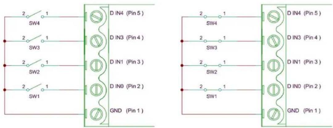
9.3 Digital Outputs: SINK
The \~@-XXX outputs are current sinking outputs, they can easily pull the output down to ground but they cannot pull the output up.
These Sink Outputs act like a switch shorting the @igital Output to the GN@ pin.
hen the Output is off the external, customer supplied, circuit pulls up to its supply Ωoltage, Ωss.

The ED-XXX outputs are current sinking outputs, they can easily pull the output down to ground but they cannot pull the output up.
The +ve supply, Ωss, to the load isn't related in any way to the ED power supply voltage,
Ensure that the external circuit Ground is connected to the ED Gnd connection.
The Maximum Current one ED port can sink is 1 Amp so large loads can be switched.
$$ \mathrm{Vss} = 3 0 \mathrm{VMax} $$

9.4 Digital Outputs: TTL Compatible
TTL outputs must drive below 0.35Ω for logic Low, and above 3.3Ω for logic High.
The ED outputs can drive down to below 0.35Ω while sinking over 1A, so the Low side of the output spec is not a problem.
ED Sink outputs do not drive high, to make the outputs TTL (or 5Ω CMOS) compatible, add a pull-up resistor, say 10kΩ, from the outputs to 5Ω.
Ensure the external circuit Ground is connected to ED GND connection.

9.5 Turning ON Indicator Light
The ED-XXX outputs are current sinking outputs, they can easily pull the output down to ground but they cannot pull the output up.
hen an LED and resistor is connected as shown the LED lights when the Output is turned ON.
12Ω supply, 20mA current, 500 Ohm R.

The ED-XXX outputs are current sinking outputs, they can easily pull the output down to ground but they cannot pull the output up.
hen RS part# 719-2522, 7 Segment Display, is connected
12Ω supply, Ωf=7.8Ω 20mA current, 210 Ohm R
8 x 20mA = 160mA still a small load even when all 7 segments plus decimal point are lit.

9.6 Turning ON Indicator Sounds
The ED-XXX outputs are current sinking outputs, they can easily pull the output down to ground but they cannot pull the output up.
hen a Buzzer RS Part# 754-2003, and resistor are connected as shown the Buzzer sounds when the Output is turned ON.
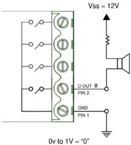
9.7 Digital Inputs: NPN/PNP Compatible
ED-XXX Has 8 Digital Inputs.
Each Input can be individually set to accept either NPN or PNP signals.
Demo: ED-XXX IP address is 192.168.127.253
My PC IP= 192.168.127.250
NPN PNP Jumpers

ED-XXX Has 8 Digital Inputs.
Each Input can be individually set to accept either N+N or +N+ signals.
Set to LEFT For +N+.
Set to RIGHT for N+N.

9.8 Digital Input/Output
A N+N Sensor
N+N +proximity Sensor Output is normally HIGH when nothing is near it
N+N +proximity Sensor Output goes LO> when metal object is near it
A+N+ Sensor
+N+ +proximity Sensor Output is normally LO> when nothing is near it
+N+ +proximity Sensor Output goes HIGH when metal object is near it


flowchart
graph TD
    A["PNP"] --> B["BROWN"]
    B --> C["BLACK"]
    B --> D["BLUE"]
    C --> E["+"]
    D --> F["-"]
Each sensor requires a Power Input of 12 Ωolts
A PNP Sensor is on DIO 5 = 020x
PNP Proximity Sensor Output is normally LO> when nothing is near it
PNP Proximity Sensor Output goes HIGH when metal object is near it
A NPN Sensor is on DIO 0 =01x
NPN Proximity Sensor Output is normally HIGH when nothing is near it
NPN Proximity Sensor Output goes LO> when metal object is near it

9.9 Dry Contacts
A "Dry" contact is so called because it doesn't have any voltage on it.
A switch is a typical dry contact.
Problem: If there is no voltage on it how do I tell whether its open or closed?
Switch is DI 02= Bit 4

natural_image
Close-up of a black toggle switch with a red indicator light (no visible text or symbols)
natural_image
Close-up of a black industrial electrical switch with a red indicator light and mounting base (no visible text or symbols)9.10 Detecting Dry Contacts
Set the User ]onfigurable PNP7NPN Jumper to NPN
Dry Contact / Ωolt Free:
Logic Level 0: Short to GND
Logic Level 1: Leave unconnected, inputs pull high
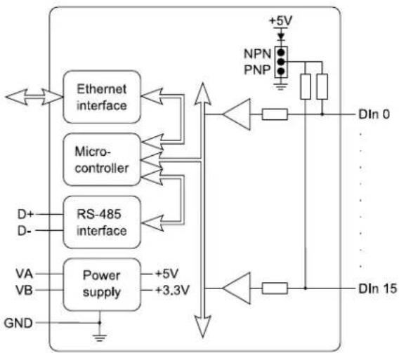
flowchart
graph TD
    A["Ethernet interface"] --> B["Microcontroller"]
    C["RS-485 interface"] --> B
    D["Power supply"] --> E["+5V"]
    D --> F["+3.3V"]
    B --> G["+5V"]
    G --> H["NPN PNP"]
    H --> I["DIn 0"]
    H --> J["DIn 15"]
    K["GND"] --> L["Ground"]
    M["D+"] --> N["RS-485 interface"]
    O["D-"] --> N
    P["VA"] --> N
    Q["VB"] --> N
    R["+5V"] --> S["Diode"]
    T["Diode"] --> U["Resistor"]
    V["Diode"] --> W["Resistor"]
9.11 Dry Contact: PIR Detector
Inputs: A relay is a dry contact.
PIR Alarm = DIO 1 = 02x

9.12 Sensors & Actuators
Sensors:
Sensors: Connect to Inputs
Sensor: a mechanical device sensitive to light, temperature, radiation level, or the like, that transmits a signal to a measuring or control instrument.
*ctuators:
Actuators: Connect to Outputs
hat can I Control?
Actuator: a servomechanism that supplies and transmits a measured amount of energy for the operation of another mechanism or system.
10 Lifetime Warranty and Support
To receive the lifetime Warranty, you need to register your product with us using our online form.
NB: this must be done within 28 days of Purchase.
Lifetime >arranty Sign up


* Terms and Conditions are available online. Standard warranty period is 3 years if a product is not registered.
Since 1983, Brainboxes have designed, tested and manufactured our products all under one Roof. One of our greatest strengths is in after sales service. Technical Support is provided by members of our Test Team, who know our products inside out and have direct access to the chip and board designers as well as the technicians who built and tested your product.
If you have any issues, questions or suggestions about our Products and Services,
then please contact us.
Technical Support is free*. As long as you have a Brainboxes Product we will be happy to help, even if it's discontinued or out of warranty. Excellent Customer Service, just as it should be.
For the quickest solution to your issue, if you email us, please include as much detail of your setup and the fault you are experiencing.
* Standard rate call charges for phone support apply.
Technical Support: support@Brainboxes.com
Sales Enquiries: sales@Brainboxes.com
Telephone
=ou can speak to Brainboxes Support or Sales teams direct,
Monday – Friday, 9am to 5pm (UK time)
Tel: +44 (0)151 220 2500
11 Regulatory Approvals 7 Compliance
For up to date details of global certifications, please check the product datasheet on the Brainboxes website: www.brainboxes.com
11.1 Company Accreditation
Brainboxes is accredited to internationally recognised standards for our Quality and Environmental Management Systems. Our ISO9001 Quality System was first accredited in 1994, followed by our ISO14001 Environmental System in 2008. These standards help ensure we can demonstrate effective management of all our quality systems and our environmental impacts, together with a process of continuous improvement.
All our Quality systems are subject to internal and external assessment on a regular basis. Copies of Certificates are available for download from our website: www.brainboxes.com
Linked with our Lean and Six Sigma techniques, we believe we have the most reliable products on the market, and to back this up we are offering a Lifetime >arranty* on all our Serial +products.
11.2 Europe – EU Declaration of Conformity
Brainboxes products are designed to conform to the protection requirements of European Council Directive 2004/108/EC and its subsequent revisions.
A Declaration of Conformity and supporting Technical Construction File is available by request from Brainboxes, and will identify any updated legislation that may have been introduced since the publication of this Manual.
Warning: This is a Class A +roduct. In a domestic environment this product may cause interference in which case the user may be required to take adequate measures to address this.
11.3 WEEE Directive (Waste Electrical and Electronic Equipment)
The >aste Electric and Electronic Equipment (>EEE) Regulations 2013 became law in the UK on the 1st of January 2014 and replaced the 2006 Regulations. Brainboxes is fully compliant with this legislation.
Customer Responsibilities
=ou are encouraged to dispose of >EEE in an environment friendly way.
This can be done through your local civic amenities site, an approved treatment facility or alternatively through a relevant compliance scheme.
Brainboxes' Responsibilities
Brainboxes has a legal responsibility, as producer, to provide a free of charge collection service to our customers for our obligated >EEE.
Brainboxes is defined as a producer under the >EEE regulations because we sell own brand Electrical & Electronic Equipment (EEE) in the UK. Our >EEE +roducer Registration Number is >EE/AH0004XR.
For details of our >EEE recovery service options, please see our >ebsite, or email us at:
weerecovery%Brainboxes.com
11.4 RoHS Compliance
All Brainboxes Serial and Bluetooth products are fully RoHS compliant.
Brainboxes identified at an early stage the importance of rapid compliance to RoHS guidelines and established a project team to actively manage the transition. The initial step in the process was to use our close relationships with suppliers to ensure early access to RoHS compliant components for all of our Bluetooth and Serial Products. In addition, the project team worked to ensure that our manufacturing processes meet all RoHS requirements well in advance of the deadline.

To verify supplier declarations on RoHS compliancy, we have also sent fully built products to an external test house for X-Ray system XDAL. This technique is capable of determining percentages of different elements and is accurate to 0.1% >t.
RoHS Compliant Brainboxes products have been available since January 2005.
hat is the RoHS Directive?
The Restriction of the Use of Certain Hazardous Substances (RoHS) in Electrical and Electronic Equipment (EEE) Directive (2011/65/EU) was transposed into UK law on 2 January 2013.
This legislation bans the placing on the EU market of new EEE containing more than the agreed levels of:
lead (Pb)
cadmium (Cd)
mercury (Hg)
hexavalent chromium (Cr6+)
polybrominated biphenyls (PBB)
polybrominated diphenyl ethers (PBDE)
Any future revisions to this legislation will be complied with, and identified in a Declaration of Conformity, available on request.
14 Copyright
Copyright © Brainboxes Ltd
All rights reserved. No part of this hardware, software, circuitry or manual may be duplicated, copied, transmitted or reproduced in any way without the prior consent of the Manufacturer.
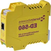


- [rainboxes 9thernet to Digital IO
- Contents
- Introduction
- Before you start
- Box Contents
- Requirements
- Supported Operating Systems
- System Requirements
- Network Requirements
- Hardware Features
- ED Range – Industrial
- ED Range – Light Industrial
- Usability Features
- Technical Specifications
- Network connection
- Power
- Storage and Operating Environment Guidelines
- L9D indicators
- Circuit Diagrams
- 9D8664
- 9D8264
- 9D8564
- Pinouts:
- Terminal [lock]onnector Pinout (Light Industrial)
- RS-232 Standard
- Device Dimensions
- Light Industrial Devices
- Reset Button
- Manual Reboot
- Manual ©ard Restore
- Input/Output Specification
- Relay Information (9D-538, 9D-038 Only)
- Firewall 9xceptions and Port Numbers
- Getting Started
- Connecting your ED device
- Configuring your device settings
- Boost.IO Manager
- Introduction
- Installing Boost.IO Manager
- Finding and Installing an ED device
- COM Port Settings
- ]TS \*Iways True
- \*dvanced ]OM Port Settings
- ]OM Number
- Port \*accessible When Device is Offline
- T]P7IP Settings
- Alternate Access Methods
- Adding a Device by IP Address
- Adding a Device by MAC Address
- Add Device Manually - Step 1 of 2
- Important Note:
- Add Device Manually - Step 2 of 2
- IP Addressing
- Rebooting Device
- Restoring Factory Settings
- Firmware Upgrade
- Proxy Server Settings
- Device Swapping
- Adding a Remote Device Using Boost.IO
- Remote Access
- Web Configuration Pages
- Introduction
- Home page
- Device Information
- ]urrent Protocol
- ]onnections
- Protocol Statistics
- Device IP Settings
- Update Interval
- Network page
- Network IP \*address
- Web Server7UPnP
- Serial Port page
- Serial Port 1
- Default Serial Port Settings
- Protocol Settings
- Save
- Cancel Changes
- \*Iways Use These Settings
- Protocol Type
- Local T]P Port
- ]onnection Timeout
- Protocol page
- \*S]II Protocol Settings
- Device \*address
- T]P Port
- Idle Timeout
- ]ounter Update Direction
- ]ounter Mode
- ]hecksum
- Input Polarity
- Output Polarity
- Serial 'ateway
- [aud Rate
- ]ommand Timeout
- Console page
- Terminal Console
- IO Lines page
- Power8On Value
- Safe Value
- Iso, the output lines will be set to the state which has been set on the I" Lines page.
- Quick Stop Value
- Device Management page
- Device Management
- Factory Default Settings
- Configuration Tables
- Baud Rate Settings (BB)
- Data Format Settings (FF)
- Digital Input/Output Data Characters Format
- ASCII Protocol
- Introduction
- Command Format
- Response Format
- %AANNTTCCFF
- #\*\*
- Response:
- Examples:
- #AA00DD
- #AA0ADD
- #AA0BDD
- #AA1cDD
- #AAAcDD
- #AABcDD
- #AAN
- \$AA2
- \$AA4
- \$AA5
- \$AA6
- \$AAC
- \$AACN
- \$AAF
- \$AALS
- \$AAM
- \$AAS1
- \$AARS
- @AA
- @AA(Data)
- \~AAO(Name)
- 8.26\~\*\*
- \~AA0
- \~AA1
- \~AA2
- \~AA3EVV
- \~AA4V
- \~AA5V
- Worked Hardware Examples
- Output to a Light Circuit.
- Switch Input Circuit
- Digital Outputs: SINK
- Digital Outputs: TTL Compatible
- Turning ON Indicator Light
- Turning ON Indicator Sounds
- Digital Inputs: NPN/PNP Compatible
- Digital Input/Output
- Dry Contacts
- Detecting Dry Contacts
- Dry Contact: PIR Detector
- Sensors & Actuators
- Lifetime Warranty and Support
- Regulatory Approvals 7 Compliance
- Company Accreditation
- Europe – EU Declaration of Conformity
- WEEE Directive (Waste Electrical and Electronic Equipment)
- Customer Responsibilities
- Brainboxes' Responsibilities
- RoHS Compliance
- Copyright
- Copyright © Brainboxes Ltd
Brand : Brainboxes
Model : ED-004
Category : Industrial network interface