
ARC-8026-16 - Boîtier d'extension informatique Areca - Free user manual and instructions
Find the device manual for free ARC-8026-16 Areca in PDF.


| Product Type | RAID Controller |
| Brand | Areca |
| Model | ARC-8026-16 |
| Interface | PCI Express 3.0 x8 |
| Internal Ports | 8 SATA/SAS (16 lanes) |
| Supported Drive Types | SATA HDD/SSD, SAS HDD/SSD |
| RAID Levels | 0, 1, 5, 6, 10, 50, 60, JBOD |
| Cache Memory | 1GB DDR3 (expandable to 4GB) |
| Dimensions (W x D x H) | 200mm x 120mm x 30mm |
| Weight | 200g (approx) |
| Power Consumption | 15W typical |
| Operating Temperature | 0°C to 60°C |
| Storage Temperature | -20°C to 80°C |
| Cooling | Passive heatsink |
| Operating System Support | Windows, Linux, macOS, VMware |
| Key Functions | RAID management, hot-swap, background rebuild, S.M.A.R.T. monitoring, online capacity expansion |
| Warranty | 3 years |
| Maintenance | Clean with dry cloth; avoid moisture and static discharge |
| Safety | Handle with ESD precautions; install in a well-ventilated chassis |
| Spare Parts & Repairability | Not user-serviceable; contact authorized support for repairs |
Frequently Asked Questions - ARC-8026-16 Areca
User questions about ARC-8026-16 Areca
0 question about this device. Answer the ones you know or ask your own.
Ask a new question about this device
Download the instructions for your Boîtier d'extension informatique in PDF format for free! Find your manual ARC-8026-16 - Areca and take your electronic device back in hand. On this page are published all the documents necessary for the use of your device. ARC-8026-16 by Areca.
USER MANUAL ARC-8026-16 Areca
Copyright and Trademarks
The information of the products in this manual is subject to change without prior notice and does not represent a commitment on the part of the vendor, who assumes no liability or responsibility for any errors that may appear in this manual. All brands and trademarks are the properties of their respective owners. This manual contains materials protected under International Copyright Conventions. All rights reserved. No part of this manual may be reproduced in any form or by any means, electronic or mechanical, including photocopying, without the written permission of the manufacturer and the author.
FCC Statement
This equipment has been tested and found to comply with the limits for a Class B digital device, pursuant to part 15 of the FCC Rules. These limits are designed to provide reasonable protection against interference in a residential installation. This equipment generates, uses, and can radiate radio frequency energy and, if not installed and used in accordance with the instructions, may cause harmful interference to radio communications. However, there is no guarantee that interference will not occur in a particular installation.
Manufacturer's Declaration for CE Certification
We confirm ARC-8026 SAS expander box has been tested and found comply with the requirements set up in the council directive on the approximation of the low of member state relating to the EMC Directive2004/108/EC. For the evaluation regarding to the electromag-netic compatibility, the following standards where applied:
EN 55022: 2006, Class B
EN 61000-3-2: 2006
EN 61000-3-3: 1995+A1: 2001+A2: 2005
EN 55024:1998+A1:2001=A2:2003
IEC61000-4-2: 2001
IEC61000-4-3: 2006
IEC61000-4-4: 2004
IEC61000-4-5: 2005
IEC61000-4-6: 2006
IEC61000-4-8: 2001
IEC61000-4-11: 2004
Contents
1. Introduction ...... 4
1.1 Overview ....4
1.2 Technical Specifications ....4
2. Hardware Installation 6
2.1 Before Your Begin Installation 6
2.2 Board Layout & Outline ......7
2.3 Installation 10
3. LCD Configuration Manager 19
3.1 Using Local Front Panel Touch-Control Keypad 19
3.2 Navigation Map of the LCD 21
4. CLI Manager 24
4.1 Expander RS-232C Port Pin Assignment 25
4.2 Start-up VT100 Screen 25
4.3 CLI Command 29
- HELP Command 29
- PASS Command 29
- LO Command 30
- LINK Command 30
- TH Command 32
- GROUP Command 34
- SYS Command 36
- BU Command 37
• FAN Command 38 - SPIN Command 39
- ST Command 40
- LSD Command 40
- SHOWLOGS Command 42
- Counters Reset Command 44
- Sasaddr Command 45
1. Introduction
1.1 Overview
The Areca SAS expander module ARC-8026 is based on the LSI 36-port LSISAS2x36 expander IC, SAS-2 chip which features 36 x 6Gb/s ports and 6G/3G multiplexing, SAS 2.0 zoning, self-configuration, table-to-table routing, and an integrated PPC processor for SES-2 and enclosure management support. The ARC-8026 expander board features three 6Gb/s SAS 4x SFF-8088 ports; one host and two for expansion to additional JBOD enclosures. It is designed to fit into a stand-alone box and can be installed in a 5.25"mounting shell. The Areca SAS expander box is ideal for enclosure customers that want to support up to 24 channels 6Gb/s and 3Gb/s SAS/SATA JBOD function units using low-cost SFF-8087 SAS cables. The expander box can be daisy-chained additional enclosures to provide more disk connection. It has been fully tested and qualified with 6Gb/s and 3Gb/s Areca external SAS/Fibre/iSCSI/PCIe to SAS RAID controller, SAS RAID adapters and HBAs.
The expander box contains an embedded expander manager that can access via in-band SES-2 over SMP protocol and out-of band RS-232 port. The Areca expander firmware and EPLD has implemented the SES-2 protocol and disk activity map to SGPIO based indicator LEDs. For backplane without SGPIO supporting, the expander box also provides two kinds of alternative LED cable header to support the individual fault/activity status indicator for those backplanes. In addition to meet different enclosure, ARC-8026 expander box has implemented autonomous enclosure management of two power supplies status connectors, four fan monitor/speed control connectors through the SES-2 protocol. Firmware and configuration data including vendor identification strings can be customized or tuned for each customer.
1.2 Technical Specifications
Enclosure Controller Modules
- Expander Board:
1 modules - Sensors:
1 sensor per expander board
Controller External Connectors
SAS Connectors
- 1 SAS "IN" connector for connection to the host
- 2 SAS "OUT" connector for expansion to next JBOD enclosure
Drives
SAS Hot-Plug Hard Drives
- Up to 12/16/24 6.0 Gb/s SAS hard drives at speed of 10K or 15K rpm
SATA Hot-Plug Hard Drives
- Up to 12/16/24 6.0 Gb/s SATA hard drives at speeds of 7.2K or 10K rpm
Internal Connectors
• 3/4/6 SFF-8087 min-SAS connectors
- 1 x 6-pin PCI-E power connector
- 4 x 3-pin fan connector
- 2 x 2-pin power status connector
- 1 x 6-pin LCD connector
Serial Connector (per Expander Board)
- 1 x 6-pin UART RJ-11 connector (for expander box manager only)
LED Indicators
Internal fault/activity header
• 12/16/24 2.54mm activity and fault header
External SAS Port LED Indicators
- Expander two one-color LED status indicators for each SAS port, one for SAS port link and one for the activity status
Physical
- 41(H) x 145(W) x 200(D) mm
Environmental
Temperature
- Operating 10° to 40° C
- Storage -40° to 70°C
Relative Humidity
- Operating 10% to 80% (non-condensing)
• Storage 5% to 95% (non-condensing)
2. Hardware Installation
This section describes the procedures for installing the cable solution external ARC-8026 expander box.
2.1 Before Your Begin Installation
Thanks for purchasing the cable solution external ARC-8026 SAS expander as your data storage subsystem. This user manual gives simple step-by-step instructions for installing and configuring the SAS expander box. To ensure personal safety and to protect your equipment and data, reading the following information package list carefully before you begin installing.
Package Contents
Open the package carefully, and make sure that none of the items listed below are missing.
The ARC-8026 expander box kit may have included the following items in the shipping package:
- ARC-8026 expander box with LCD module
- 1 x RJ11 to RS-232 DB9 cable
- 1 x User manual
- 8 x drive mounting screws (4 screws for each side)
- Adapter convert two 4 pin peripheral power cables into a PCI-E power cable
If any item is missing or damaged, please contact your local resellers for service.
2.2 Board Layout & Outline
The ARC-8026 expander box can support a family included 3/4/6 internal SFF-8087 ports with additional 3 external SFF-8088 ports. This section provides the board layout and connector/jumper for the SAS expander box.

Figure 2-1, ARC-8026 expander box
| Connector Description Type | |||
| 1. (SCN3) | 6Gb/s SAS Expander In/Out (CH2) SFF-8088 | ||
| 2. (SCN2) | 6Gb/s SAS Expander In (CH1) SFF-8088 | ||
| 3. (SCN1) | 6Gb/s SAS Expander Out (CH0) SFF-8088 | ||
| 4. (D3) | LED for Expander In/Out Link and Access | Bi-color DIP | |
| 5. (D2) | LED for Expander In Link and Access B | -color DIP | |
| 6. (D1) | LED for Expander Out Link and Access | Bi-color DIP | |
| 7. (J1) | RS232 for Expander Configuration RJ11 | Connector | |
| 8. (J3) | LCD Connector 6-Pin Controller Header | ||
| 9. (FAN1) | Fan1 with RPM Sense 3-Pin Connector | ||
| 10. (FAN2) | Fan2 with RPM Sense 3-Pin Connector | ||
| 11. (FAN3) | Fan3 with RPM Sense 3-Pin Connector | ||
| 12. (FAN4) | Fan4 with RPM Sense 3-Pin Connector | ||
| 13. (SW2) | Fan/Power Detective Control Function | Micro DIP-Switch ENABLE: Monitor function enable.DISABLE: Monitor func-tion disable. | |
| SW2(2) PW_FLT1 | STATUS | ||
| ON ENABLE | |||
| OFF DISABLE | |||
| SW2(3) PW_FLT2 | STATUS | ||
| ON ENABLE | |||
| OFF DISABLE | |||
| SW2(4) FAN CONTROL | |||
| ON ENABLE | |||
| OFF DISABLE | |||
| 14. (SW1) | Fan1-Fan4 Input Definition | Micro DIP-Switch | |
| SW1(1-4) FAN_NO. | |||
| OFF OFF OFF OFF 0 | |||
| ON OFF OFF OFF 1 | (Fan1) | ||
| ON ON OFF OFF 2 | (Fan1~Fan2) | ||
| ON ON ON OFF 3 | (Fan1~Fan3) | ||
| ON ON ON ON 4 | (Fan1~Fan4) | ||
| 15. (J5) | Power 1 Status Input 2-Pin Header | ||
| 16. (J6) | Power 2 Status Input 2-Pin Header | ||
| 17. (JP1) | Individual Activity LED Header for 6Gb/s SAS 1-8 Ports | 8-Pin Header | |
| 18. (JP2) | Individual Activity LED Header for 6Gb/s SAS 9-16 Ports | 8-Pin Header | |
| 19. (JP3) | Individual Activity LED Header for 6Gb/s SAS17-24 Ports | 8-Pin Header | |
| 20. (JP4) | Individual Fault LED Header for 6Gb/s SAS 1-8 Ports | 8-Pin Header | |
| 21. (JP5) | Individual Fault LED Header for 6Gb/s SAS 9-16 Ports | 8-Pin Header | |
| 22. (JP6) | Individual Fault LED Header for 6Gb/s SAS 17-24 Ports | 8-Pin Header | |
| 23. (SCN4) | 6Gb/s SAS 1-4 Ports (Internal) SFF-80B7 | ||
| 24. (SCN5) | 6Gb/s SAS 5-8 Ports (Internal) SFF-80B7 | ||
| 25. (SCN6) | 6Gb/s SAS 9-12 Ports (Internal) SFF-8087 |
| 26. (SCN7) | 6Gb/s SAS 13-16 Ports (Internal) SFF-8087 |
| 27. (SCN8) | 6Gb/s SAS 17-20 Ports (Internal) SFF-8087 |
| 28. (SCN9) | 6Gb/s SAS 21-24 Ports (Internal) SFF-8087 |
| 29. (J8) | PCIE Power Connector 6-Pin Connector |
Table 2-1, ARC-8026 expander box connectors
Note:
• Fan Headers (FAN1\~FAN4)
The box has four 4 3-pin fan headers which can control and detect the fan speed. Each header can only connect to one fan. You can directly connect the enclosure cooling fan to those 3-pin header. Controller hardware monitor can check the RPM status of the cooling fans and show those fan status on the controller's hardware information based on the SW1 micro switch definition (Fan1-Fan4). SW2 (3) micro dip-switch is used to control the fan monitor function. Current limitation of each fan header is 6A.
• Power Status Input Headers (J5 and J6)
Power status 2-pin input headers monitors enclosure two power supply status output pin based on the SW2 (1 and 2) micro dip-switch.
Pin definition for J5 and J6.
Pin 1: GND
Pin 2: Single Input; Low: power fail, High: power ok
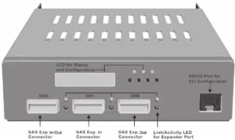
Figure 2-2, Front view of ARC-8026 expander box
The following describes the ARC-8026 expander box link/activity LED.
| SAS Host Port LED Status | |
| Link LED(Green light) | When host port link LED is illuminated for 1 second and turns off for 3 seconds that indicates the one link has connected.When host port Link LED is illuminated for 2 seconds and turns off for 2 seconds that indicates the two links have connected.When host port Link LED is illuminated for 4 seconds that indicates the four links have connected. |
| Activity LED(Blue light) | When activity LED is illuminated that indicates the SAS host accesses to the ARC-8026 expander box. |
2.3 Installation
The ARC-8026 expander box housed in a 5½-inch half-height canister with a removable LCD module, a host channel, two expander and a RS-232 CLI port controller. The expander controller is provided for customers who want to use the exiting SAS/SATA enclosure. It is designed to fit into one 5½-inch half-height drive bays located in a server chassis or storage case. Standard mounting holes are located on both sides of the controller canister. These mounting holes accept commonly available No. 6-32 coarse-thread screws. Use the following instructions below to install the ARC-8026 expander box.
Step 1. Power the Enclosure Off
Turn off the enclosure and remove the AC power cord. Remove the enclosure's cover. For the instructions, please see the enclosure documentation.
Step 2. Unpack ARC-8026 Expander Box
Unpack and remove the ARC-8026 expander box from the package. Inspect it carefully, if anything is missing or damaged, contact your local dealer.
Step 3. Mounting ARC-8026 Expander Box into the Enclosure
Remove the enclosure cover and find a 5.25 inch CD-ROM wide place to fasten the ARC-8026 expander box in the external enclosure. The expander box requires one 5.25" half-height drive bay.
Step 4. Connecting Expander Controller Power
The ARC-8026 series expander box supports 6 pin PCI-E power connector from PCB version 1.0. If your power supply doesn't have a 6 pin PCI-E power cable then you can use the adapter to convert two 4 pin peripheral power cables into a PCI-E power cable. If you use an adapter then be sure to plug the 4 pin peripheral power connectors into separate power cables coming from the power supply.
Step 5. Install the LED Cable (option)
Please check the method which controls fault LED on the backplane. If the backplane supports SGPIO feature, ignore the individual fault LED cable connection. The preferred I/O connector for server backplanes is the Min SAS 4i (SFF-8087) internal connector. This connector has eight signal pins to support four SAS/SATA drives and six pins for the SGPIO (Serial General Purpose Input/Output) side-band signals. The SGPIO bus is used for efficient fault/activity LED management and for sensing drive locate status. See SFF 8485 for the specification of the SGPIO bus. For backplane without SGPIO supporting, Please refer to section step 5-1. LED cables for fault/activity LED cable installation.
Step 5-1. Install and Re-check Fault LED Cable Connections (option)
Make sure that the proper failed drive channel information is displayed by the fault LEDs. An improper fault LED cable connection will tell the user to "Hot Swap" the wrong drive. This can result in removing the wrong disk (one that is functioning properly) from the controller. This can result in failure and loss of system data.
The following electronics schematic is the SAS expander logical of fault/activity header. The signal for each pin is cathode (-) side.
The following diagrams and descriptions describe each type of connector.

Note:
Cables for the individual drive LEDs may come with a drive cage, or you may need to purchase them.
Connect the cables for the drive activity LEDs and fault LEDs between the backplane of the cage and the respective connector on the ARC-8026 expander box header. The following table describes the activity/fault LED.
Figure 2-3, ARC-8026
12/16/24 expander box
activity/fault LED connector

| LED Normal Status Problem Indication | ||
| Activity LED | When the activity LED is illuminated, there is I/O activity on that disk drive. When the LED is dark, there is no activity on that disk drive. | N/A |
| Fault LED | When the fault LED is solid illuminated, there is no disk present and When the fault LED is off, that disk is present and status is normal.Some controllers support the "Identify Drive" function.When the "Identify Drive" is selected, the selected drive fault LED will blank. | When the fault LED is slow blinking (2 times/sec), that indicate disk drive has failed and should be hot-swapped immediately.When the activity LED is illuminated and fault LED is fast blinking (10 times/sec) that indicate there is rebuilding activity on the disk drive. |
Step 6. Connecting SFF-8087 Cable to Backplane
The ARC-8026 expander box supports 3/4/6 SFF-8087 connectors on the back side. User uses suitable cable (depends on the backplane) to connect the expander box connector to the enclosure backplane.
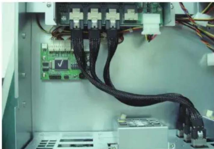
Figure 2-4, Connect ARC-8026 and backplane
Step 7. Install the Enclosure Top Cover
Check the installation thoroughly, reinstall the enclosure cover, and reconnect the power cord cables.
Step 8. Loading Drive to the Drive Tray
You can connect the SAS/SATA drives to the controller through direct cable and backplane solutions. In the direct connection, SAS/SATA drives are directly connected to SAS PHY port with SAS/SATA cables. The SAS expander module can support up to 12/16/24 PHY internal ports and 12 PHY external ports. Remove the front bezel from the computer chassis and install the cages or SAS/SATA drives in the computer chassis. Loading drives to the drive tray if cages are installed. Be sure that the power is connected to the individual drives or cage.
In the backplane solution, SAS/SATA drives are directly connected to SAS system backplane. The number of SAS/SATA drives is limited to the number of slots available on the backplane. Your ARC-8026 expander box supports up to 12/16/24 SAS or SATA 6.0-Gb/s drives, each one contained in its individual drive carrier. Each drive is hot-pluggable, allowing you to remove and insert drives without shutting down your ARC-8026 expander enclosure. Install the drives to 12-bays ARC-8026 expander enclosure as shown in figure 2-6.
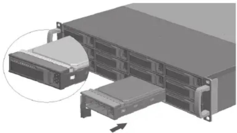
Figure 2-5, Install the drives to 12-bays ARC-8026 expander enclosure
Step 9. Connect to Host Interface
Once the ARC-8026 expander box has finished the configuration (option), then you can connect it to a host interface. The enclosure can be connected to a host interface which may a host adapter or RAID controller through the SFF-8088 SAS cable. By installing host adapter port and ARC-8026 expander box using the correct external cables which may be included in your enclosure kits. Then connect ARC-8026 expander box and host adapter port as shown below:
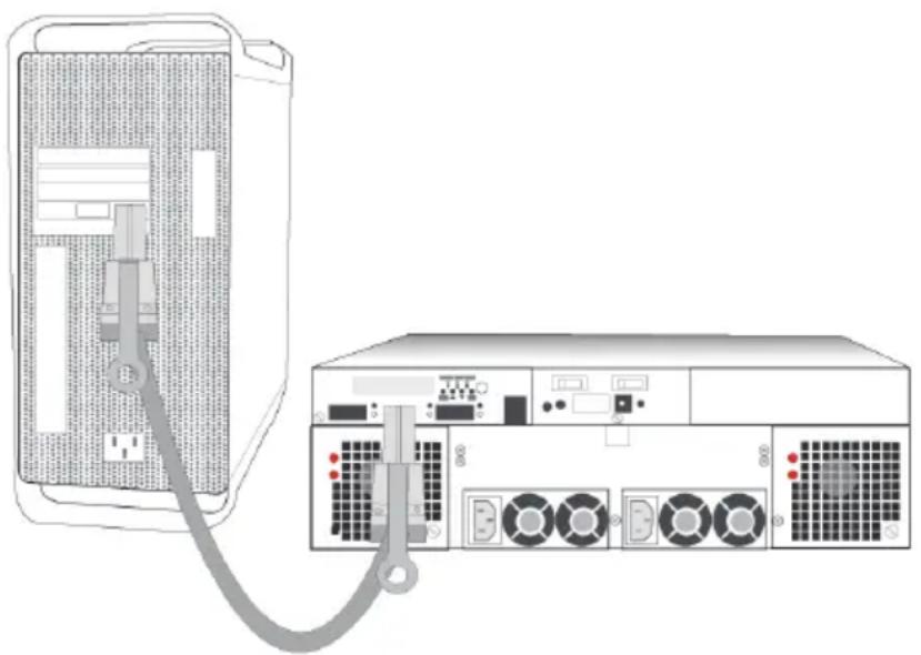
Figure 2-6, Connect ARC-8026 expander Box and host port adapter
Step 10. Connecting Expander Box's RS-232 Port (option)
The ARC-8026 expander box's system functions can be managed via a PC running a VT-100 terminal emulation program, or a VT-100 compatible terminal. The provided internal cable converts the RS-232C signals from the RJ11 into the one 9-pin D-Sub male connector.
Step 11. Add More Expander Boxes (option)
ARC-8026 expander box can run in one of two modes:
- Normal Mode
- Zone Mode
Installation Guide
You must select either mode using the CLI utility and restart the ARC-8026 expander enclosure again. The manufacture is default on the Normal Mode. Changing the mode while the ARC-8026 expander box is on. This will not affect expander operation until the ARC-8026 expander enclosure is rebooted.
In normal mode, a SAS host can communicate with up to 24 drives in the 24 bay enclosure via a single ARC-8026 expander box. ARC-8026 SAS expander box is a device that contain expander ports. Expander ports may support being attached to SAS initiator ports, SAS and/or SATA target ports, and to other expander ports. The SAS RAID controller or host adapter can support daisy-chain how many enclosures which depend on the RAID controller or the host adapter firmware. The following figure shows how to connect the external Min SAS cable from the SAS RAID controller that has external ports to the ARC-8026 expander box enclosures.
![graph TD A["ARC-8026 Expander Box\nDimension: 200(L) x 146(W) x 41(H) mm"] --> B["Link LED"] B --> C["Exp Out"] B --> D["Exp In"] B --> E["Exp Out"] B --> F["RS232"] C --> G["Areca SAS RAID Controller"] D --> G E --> G F --> G G --> H["JBOD"] H --> I["..."] H --> J["JBOD"] H --> K["JBOD"] I --> L[".…](/content/2026/05/964420/images/b2ed248e8e0da1e3d345ed66b71e3df6e93dc58899147a2658857a1f4e5fee32.jpg)
Figure 2-7, SAS expander connect to a drive box or drive enclosure
In zone mode, the SAS expander box can be split into up to 8 virtual groups. Each group drive channels and external cable connectors are assigned by CLI GROUP command. The following figure is shown the SAS expander box which has split into 2 virtual groups. Each group drive channels are controlled by individual host adapter using SAS CH1 and SAS CH2.
![graph LR A["Link LED"] --> B["Exp.In/Out"] B --> C["Exp.In"] C --> D["Exp.Out"] D --> E["RS232"] F["Activity LED"] --> G["Switch"] H["ARECA SAS RAID Adapter"] --> I["Switch"] I --> J["Switch"] style A fill:#f9f,stroke:#333 style F fill:#ccf,stroke:#333 style H fill:#cfc,stroke:#333 style I fill:#fcc…](/content/2026/05/964420/images/b4bee7fc5ec6debcc489b295bfc12246012f7b75c0d20e42823222d30c42565d.jpg)
Note:
- Please refer to chapter 4.3 CLI features of GROUP command which is used to associate the external port and the devices/phys slot.
- Turn on the expander enclosure first to make sure the SAS RAID controller or SAS host adapter recognizes the drives in the enclosure.
Step 12. Connect the Power
Connect the power cord to a grounded electronical outlet and to the expander enclosure power. Turn on the power switch at the rear of the enclosure.
Step 13. Configure ARC-8026 Expander Box
The ARC-8026 expander box is normally delivered with LCD pre-installed. Your ARC-8026 expander box can be managed by using the LCD with keypad or a serial device (terminal emulation).
• Method 1: LCD Panel with Keypad
You can use LCD front panel and keypad function to simply manage the ARC-8026 expander box. The LCD status panel also informs you of the expander's current system functions at a glance. The LCD provides a system of screens with areas for information, status indication, or menus. The LCD screen displays up to two lines at a time of menu items or other information.
Please refer to Chapter 3 LCD Configuration Manager.
The initial screen is shown as following:
![graph TD A["Command Line"] --> B["Hello! ARC-8026 > ALERTS MENU"] B --> C["Model Name"] C --> D["Status Display"] D --> E["POWER BUSY FAULT"] E --> F["ESC ENT"] E --> G["Keypad"]](/content/2026/05/964420/images/7f41b31c1cdbd975eb34d7335f603990b477a6f1ed03df2d08bd6f96c9e3c53b.jpg)
• Method 2: RS-232 Port
The ARC-8026 expander box's system functions can also be managed via a VT-100 compatible terminal or a PC running a VT-100 terminal emulation program. You can attach a serial (Character-Based) terminal or server com port to the ARC-8026 expander box for accessing the text-based setup menu. Please refer to Chapter 4 CLI Manager.
3. LCD Configuration Manager
The SAS expander box LCD configuration utility is a character-based utility that you can run after powering the unit. Use LCD configuration utility to see and configure:
- Alerts Menu,
- Voltage,
- Set Link,
- Set Alarm,
- Set Password,
- Save Config, and
- System Reset
The LCD display front panel function keys are the primary user interface for the SAS expander box. Except for the "Firmware update", all configurations can also be performed through this interface.
3.1 Using Local Front Panel Touch-Control Keypad
The front panel keypad and liquid crystal display (LCD) is the primary user interface for the SAS expander box. All configuration and management of the expander controller and its properly connected disk arrays can be performed from this interface. The front panel keypad and LCD is connected to the ARC-8026 SAS expander box to access the built-in configuration that resides in the SAS expander box's firmware.
The LCD provides a system of screens with areas for information, status indication, or menus. The LCD screen displays up to two lines at a time of menu items or other information.
The initial screen is shown as following:
![graph TD A["Command Line"] --> B["Hello! ARC-8026 > ALERTS MENU"] B --> C["Keypad"] D["Model Name"] --> E["Status Display"] E --> F["POWER BUSY FAULT"] F --> G["ESC ENT"] G --> H["Keypad"] style A fill:#f9f,stroke:#333 style D fill:#f9f,stroke:#333 style E fill:#ccf,stroke:#333](/content/2026/05/964420/images/f4a67a86c4f89392a12116b2597760592213e1189b0ab55e7b86f70b373e56d4.jpg)
Function Key Definitions:
The four function keys at the right of the front panel perform the following functions:
| Key Function | |
| Up Arrow Use to scroll the cursor Upward / Rightward | |
| Down Arrow Use to scroll the cursor Downward / Leftward | |
| ENT Key Submit selected icon function (Confirm a selected item) | |
| ESC Key Return to previous screen (Exit a selection configuration) | |
There are a variety of failure conditions that cause the ARC-8026 expander box monitoring LED to light. Below table provides a summary of the front panel LED.
| Panel LED Normal | Status Problem Indication | |
| Power LED Bright green | This LED does not light up after power switched on | |
| Busy LED (Host Access) | Blink green during host computer accessing the expander box | LED never flickers |
| Fault LED Unlit Solid | red |
3.2 Navigation Map of the LCD
The password option allows user to set or clear the SAS expander box's password protection feature. Once the password has been set, the user can only monitor and configure the SAS expander box by providing the correct password. The password is used to protect the SAS expander box from unauthorized entry. The SAS expander box will check the password only when entering the main menu from the initial screen. The SAS expander box will automatically go back to the initial screen when it does not receive any command in 5 minutes. The SAS expander box's password is default setting at 0000 by the manufacture.
The following flow is an expansion of LCM setup option items hierarchical menu.
LCM setup option items hierarchical menu:
![graph TD A["LCM Functions"] --> B["Alerts Menu"] A --> C["Voltage"] A --> D["Set Link"] A --> E["Set Alarm"] A --> F["Set Password"] A --> G["Save Config"] A --> H["System Reset"] B --> I["Power Supply Fan\nTemp. Sensor\nVoltage Sensor"] C --> J["-1.2 V-5 V-"] D --> K["Enter Password: [ * * * * "]]…](/content/2026/05/964420/images/e0b551eb5598133a7be4362bc5300ccfcd1f4c72bceedef5f690cb3fd9e2c752.jpg)
- Alerts Menu
Show which device that fail to work, its sub-items could be "Power Supply", "Fan", "Temp. Sensor" and "Voltage Sensor".
- Voltage
Show enclosure chip voltage in status data, represent in V.
The sub-items are shown as below:
1.2V-, the expander box voltage is 1.2V 5V-, the expander box voltage is 5V
For the setup item, the LCM key represent:
Up key to enter the 0 - 9 data.
Down key to enter "a" - "z" and "A" - "Z" data.
Enter key to confirm the input or ready to update a sub-item data.
Esc/Exit key to go back to the main selection.
- Set Link
Set HDD devices maximun/minimun link speed rate. the value could be 6.0G, 3.0G or 1.5G each of HDD devices link speed will have the sub-items are shown as below:
_Set Max. Rate 6.0G
_Set Min. Rate 1.5G
- Set Alarm
Set enclosure buzzer warning/critical error beep style or mute the current beep. The value could be "Sound 1", "Sound 2", "Sound 3", "Sound 4" and "Sound Disabled". Sound 1 to 4 means different frequency sound. Sound disabled means disable the sound beep. The sub-items are shown below:
_Set Alarm Beep Mute beep
Warning Alarm _Sound 2
_Critical Alarm Sound 3
- Set Password
Change the enclosure LCM/UART CLI password. The sub-item is "Set New PWD".
- Save Config
Save all the updated option value into non-volatile memory area.
- System Reset
Reboot the system.
4. CLI Manager
This Command Line Interface (CLI) is provided for you to manage the Areca ARC-8026 series 12/16/24 SAS expander system functions. The CLI is useful in environments where a graphical user interface (GUI) is not available.
- Locations of RS-232C Port
The ARC-8026 expander box uses the RJ11 port as the serial port interface. Please use the cable included on the shipping box to configure the expander controller.

- Establishing the Connection for the RS-232 Port
The CLI function can be done by using an ANSI/VT-100 compatible terminal emulation program. You must complete the appropriate installation procedure before proceeding with the CLI function. Whichever terminal emulation program is used must support the 1K XMODEM file transfer protocol.
The serial port on the ARC-8026 box's bracket can be used in VT100 mode. The provided interface cable converts the RS232 signal of the RJ11 connector on the SAS expander controller into a 9-pin D-Sub male connector. The firmware-based terminal SAS expander management interface can access the expander through this RS-232 port. You can attach a VT-100 compatible terminal or a PC running a VT-100 terminal emulation program to the serial port for accessing the text-based setup menu.
4.1 Expander RS-232C Port Pin Assignment
To ensure proper communications between the SAS expander box and the VT-100 Terminal Emulation, Please configure the VT100 terminal emulation settings to the values shown below:
| Terminal requirement | |
| Connection Null-modem cable | |
| Baud Rate 115,200 | |
| Data bits 8 | |
| Stop 1 | |
| Flow Control None | |
The controller RJ11 connector pin assignments are defined as below.
| Pin Assignment | 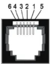 | |||
| Pin Definition Pin Definition | ||||
| 1 RTS (RS232) 4 GND | ||||
| 2 RXD (RS232) 5 GND | ||||
| 3 | TXD (RS232) 6 GND | |||
4.2 Start-up VT100 Screen
By connecting a VT100 compatible terminal, or a PC operating in an equivalent terminal emulation mode, all CLI administration functions can be exercised from the VT100 terminal.
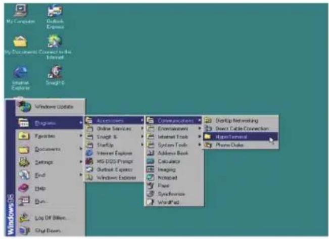
There are a wide variety of Terminal Emulation packages, but for the most part they should be very similar. The following setup procedure is an example Setup VT100 Terminal in Windows XP system using Hyper Terminal use Version 3.0 or higher.
Step 1. Open the "Taskbar Start"/"Programs"/"Accessories"/"Communications"/"Heyper Terminal". (Heyper Terminal requires version 3.0 or higher).
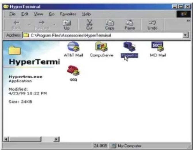
Step 2. Open "HYPERTRM.EXE".
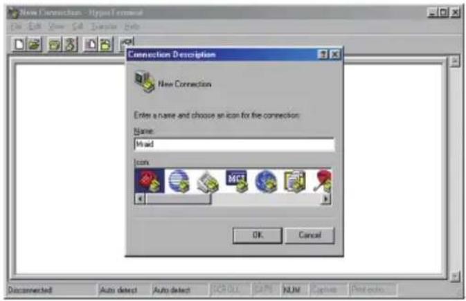
Step 3. Enter a name you prefer and then click "OK".
Step 4. Select an appropriate connecting port and then click "OK".

Step 5. Configure the port parameter settings and then click "OK".
Step 6. Open the file menu and select "Properties".
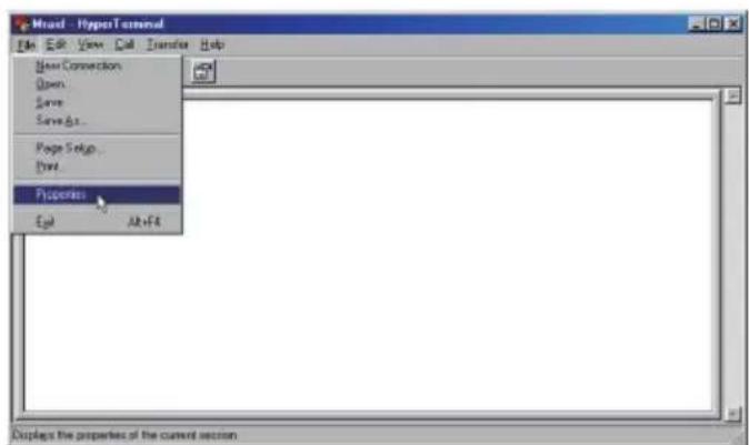
Step 7. Configure the "Connect To" setting.

Step 8. Configure the "Settings" items and then click "OK".
Function, arrow and ctrl keys act as: Terminal Keys
Backspace key sends: Crtl+H
Emulation: VT100
Telnet terminal: VT100
Back scroll buffer lines: 500

4.3 CLI Command
This section provides detail information about the SAS expander-box's CLI function. All the commands please type in lower case.
- HELP Command
This command provides an on-line table of contents, providing brief descriptions of the help sub-commands. You can use the
Syntax
CLI>help[Enter]
Example:
CLI>help
| pass | - Set Password |
| lo | - Logout CLI Shell |
| link | - Link Rate Control |
| th | - Temperature Control |
| group | - Set the PHY Group |
| sys | - System Information |
| bu | - Alarm Control |
| fan | - Fan Speed Control |
| spin | - Drive SpinUp Control |
| st | - Store System Setting |
| lsd | - List Devices Status |
| showlogs | - Show the Current Logs |
| fld | - File Download |
| counters reset(optional) | -Display/Reset all phy counters |
| sasaddr | -Display expander SAS address |
- PASS Command
The pass command allows user to set or clear the expander box password protection feature. Once the password has been set, the user can only monitor and access the expander box setting by providing the correct password. The password can accept max.
8 chars and min. 4 chars. The manufacture default password is "0000".
Syntax
CLI>pass [Enter]
Example:
CLI>pass
Old Password:****
New Password:****
Verify New Password:****
Password Changed But Not Save Permanently!
Note, use CLI command "st" to keep permanently.
- LO Command
To exit the selected expander box CLI shell, use the lo command.
Syntax
CLI> lo [Enter]
Example:
CLI>lo
Password:
- LINK Command
The link command allows you to set the operate device link rate that has been connected on expander controllers. Typical parameters include: Max and Min disk speed connected the SAS expander box.
Syntax
CLI>link [Index Max Min] [Enter]
Index: Slot Index
Max, Min: speed code, 8 means 1.5G, 9 means 3.0G and
10 means 6.0G
PS. Pls. Save Config. & Reboot To Take Effect
CLI>st
Example:
CLI>link
ArrayDevice Element (0x17):
| NAME | PHY | NLR | MAX | MIN | TYPE | ADDRESS |
| SLOT 01 | 0 | 3.0G | 10 | 8 | SAS | 5000C500-0D2002D1 |
| SLOT 02 | 1 | 10 | 8 | |||
| SLOT 03 | 2 | 10 | 8 | |||
| SLOT 04 | 3 | 1.5G | 10 | 8 | SATA | 5001B469-84965C03 |
| SLOT 05 | 4 | 10 | 8 | |||
| SLOT 06 | 5 | 10 | 8 | |||
| SLOT 07 | 6 | 6.0G | 10 | 8 | SAS | 5000C500-17C8FD25 |
| SLOT 08 | 7 | 10 | 8 | |||
| SLOT 09 | 8 | 10 | 8 | |||
| SLOT 10 | 9 | 10 | 8 | |||
| SLOT 11 | 10 | 10 | 8 | |||
| SLOT 12 | 11 | 10 | 8 |
//Set the slot 0x6 max. speed to 1.5G
CLI >link 6 9 8
CLI >link
ArrayDevice Element (0x17):
| NAME | PHY | NLR | MAX | MIN | TYPE | ADDRESS |
| SLOT 01 | 0 | 3.0G | 10 | 8 | SAS | 5000C500-0D2002D1 |
| SLOT 02 | 1 | 10 | 8 | |||
| SLOT 03 | 2 | 10 | 8 | |||
| SLOT 04 | 3 | 1.5G | 10 | 8 | SATA | 5001B469-84965C03 |
| SLOT 05 | 4 | 10 | 8 | |||
| SLOT 06 | 5 | 10 | 8 | |||
| SLOT 07 | 6 | 6.0G | 9 | 8 | SAS | 5000C500-17C8FD25 |
| SLOT 08 | 7 | 10 | 8 | |||
| SLOT 09 | 8 | 10 | 8 | |||
| SLOT 10 | 9 | 10 | 8 | |||
| SLOT 11 | 10 | 10 | 8 | |||
| SLOT 12 | 11 | 10 | 8 |
CLI>st
CLI>
Reboot to take effect.
CLI >link
ArrayDevice Element (0x17):
| NAME | PHY | NLR | MAX | MIN | TYPE | ADDRESS |
| SLOT 01 | 0 | 3.0G | 10 | 8 | SAS | 5000C500-0D2002D1 |
| SLOT 02 | 1 | 10 | 8 | |||
| SLOT 03 | 2 | 10 | 8 | |||
| SLOT 04 | 3 | 1.5G | 10 | 8 | SATA | 5001B469-84965C03 |
| SLOT 05 | 4 | 10 | 8 | |||
| SLOT 06 | 5 | 10 | 8 | |||
| SLOT 07 | 6 | 3.0G | 9 | 8 | SAS | 5000C500-17C8FD25 |
| SLOT 08 | 7 | 10 | 8 | |||
| SLOT 09 | 8 | 10 | 8 | |||
| SLOT 10 | 9 | 10 | 8 | |||
| SLOT 11 | 10 | 10 | 8 | |||
| SLOT 12 | 11 | 10 | 8 |
- TH Command
The th command allows you to set the operate device temperature warning limit. Typical parameters include: High-Warn and Low-Warn are warning temperature in Celsius.
Syntax
CLI> th Index High-Warn Low-Warn
Example:
CLI>th
Temperature Element (0x04):
| NAME | ID | CT(‘C) | HTW | LTW | OTWarn |
| ENC. Temp | 01 | 30 | 60 | 5 | No |
| Chip Temp | 02 | 64 | 85 | 5 | No |
| Slot01 Temp | 03 | 31 | 60 | 5 | No |
| Slot02 Temp | 04 | 32 | 60 | 5 | No |
| Slot03 Temp | 05 | 30 | 60 | 5 | No |
| Slot04 Temp | 06 | 31 | 60 | 5 | No |
| Slot05 Temp | 07 | 36 | 60 | 5 | No |
| Slot06 Temp | 08 | 32 | 60 | 5 | No |
| Slot07 Temp | 09 | 32 | 60 | 5 | No |
| Slot08 Temp | 10 | 35 | 60 | 5 | No |
| Slot09 Temp | 11 | 34 | 60 | 5 | No |
| Slot10 Temp | 12 | 32 | 60 | 5 | No |
| Slot11 Temp | 13 | 32 | 60 | 5 | No |
| Slot12 Temp | 14 | 33 | 60 | 5 | No |
CLI>th 2 79 0
Temperature Element (0x04):
| NAME | ID | CT(°C) | HTW | LTW | OTWarn |
| ENC. Temp | 01 | 30 | 60 | 5 | No |
| Chip Temp | 02 | 64 | 79 | 0 | No |
| Slot01 Temp | 03 | 31 | 60 | 5 | No |
| Slot02 Temp | 04 | 32 | 60 | 5 | No |
| Slot03 Temp | 05 | 30 | 60 | 5 | No |
| Slot04 Temp | 06 | 31 | 60 | 5 | No |
| Slot05 Temp | 07 | 36 | 60 | 5 | No |
| Slot06 Temp | 08 | 32 | 60 | 5 | No |
| Slot07 Temp | 09 | 32 | 60 | 5 | No |
| Slot08 Temp | 10 | 35 | 60 | 5 | No |
| Slot09 Temp | 11 | 34 | 60 | 5 | No |
| Slot10 Temp | 12 | 32 | 60 | 5 | No |
| Slot11 Temp | 13 | 32 | 60 | 5 | No |
| Slot12 Temp | 14 | 33 | 60 | 5 | No |
CLI>st
CLI>
Reboot to take effect.
CLI>th
Temperature Element (0x04):
| NAME | ID | CT(‘C) | HTW | LTW | OTWarn |
| ENC. Temp | 01 | 30 | 60 | 5 | No |
| Chip Temp | 02 | 64 | 79 | 0 | No |
| Slot01 Temp | 03 | 31 | 60 | 5 | No |
| Slot02 Temp | 04 | 32 | 60 | 5 | No |
| Slot03 Temp | 05 | 30 | 60 | 5 | No |
| Slot04 Temp | 06 | 31 | 60 | 5 | No |
| Slot05 Temp | 07 | 36 | 60 | 5 | No |
| Slot06 Temp | 08 | 32 | 60 | 5 | No |
| Slot07 Temp | 09 | 32 | 60 | 5 | No |
| Slot08 Temp | 10 | 35 | 60 | 5 | No |
| Slot09 Temp | 11 | 34 | 60 | 5 | No |
| Slot10 Temp | 12 | 32 | 60 | 5 | No |
| Slot11 Temp | 13 | 32 | 60 | 5 | No |
| Slot12 Temp | 14 | 33 | 60 | 5 | No |
- GROUP Command
The group command is used to associate the external port with the devices/phys as one zone group. The three external cable ports and all devices/phys slots will default associate with one zone group.
Syntax
gr {dev GroupNo[1..] {ci, cj, ck,...} Start-Index(D) End-Index(D) }
gr {off | [t10 off]}
dev : use drive slot index
GroupNo : groupno start from 1, max 8 groups ci, cj, ck,...: external cable connector. i, j, k,... is the index which range from 0 to 3. According to view from connector side, index start from right to left or top to bottom. The cable c0, c1, or c2 is view from right to left or start from top to bottom.
Start-Index : Start slot index of zone range, [1.. max drive]
End-Index : End slot index of zone range, [1.. max drive]
off : clear the zone group setting.
t10 off : turn T10 mode off.
Example:
CLI>gr
Current PHY Group Mode: T10
Group-1: C0, C1, C2, Slot: 1, 2, 3, 4, 5, 6, 7, 8, 9, 10, 11, 12, 13, 14, 15, 16
Value: 0x0000000FFFFFFF
//Set the cable0 and slot 1 to slot 6 as group 1
CLI>gr dev 1 c0 1 6
New PHY Group Mode: T10
Group-1: C0, Slot: 1, 2, 3, 4, 5, 6
Value: 0x00000000000FFC00
Current PHY Group Mode: T10
Group-1: C0, C1, C2 Slot: 1, 2, 3, 4, 5, 6, 7, 8, 9, 10, 11, 12, 13, 14, 15, 16
Value: 0x0000000FFFFFFF
//Set the cable1 and cable2 and slot 7 to slot 16 as group 2 CLI>gr dev 2 c1, c2 7 16
New PHY Group Mode: T10
Group-1: C0, Slot: 1, 2, 3, 4, 5, 6
Value: 0x00000000000FFC00
Group-2: C1, C2, Slot: 7, 8, 9, 10, 11, 12, 13, 14, 15, 16
Value: 0x000000000FF003FF
Current PHY Group Mode: T10
Group-1: C0, C1, C2 Slot: 1, 2, 3, 4, 5, 6, 7, 8, 9, 10, 11, 12, 13, 14, 15, 16
Value: 0x0000000FFFFFFF
CLI>st
Power Cycle to reboot
CLI>gr
Current PHY Group Mode: T10
Group-1: C0, Slot: 1, 2, 3, 4, 5, 6
Value: 0x00000000000FFC00
Group-2: C1, C2, Slot: 7, 8, 9, 10, 11, 12, 13, 14, 15, 16
Value: 0x000000000FF003FF
//Clear the Zone group Setting
CLI>gr off
New PHY Group Mode: T10
Group-1: C0, C1, C2 Slot: 1, 2, 3, 4, 5, 6, 7, 8, 9, 10, 11, 12, 13, 14, 15, 16
Value: 0x0000000FFFFFFF
Current PHY Group Mode: T10
Group-1: C0, Slot: 1, 2, 3, 4, 5, 6
Value: 0x00000000000FFC00
Group-2: C1, C2, Slot: 7, 8, 9, 10, 11, 12, 13, 14, 15, 16
Value: 0x000000000FF003FF
- SYS Command
The sys command is used to view the expander's information. Typical information includes: vendor, model name, serial/unit number, expander port number, product revision, chip name/chip revision, customer code, manufacture data revision and work time.
Syntax
CLI>sys [Enter]
Example:
CLI>sys
Hardware Revision Information:-
Vendor ID : Areca Technology Co Ltd. Taiwan, R.O.C
Model ID : ARC-8026
Serial No. : 000000000000000
Unit Serial No. :
Expander SAS Address : 0x5001B46984965C3F
Product Revision : 0
Exapnder Chip ID : 0x0221 (Ports : 28)
Exapnder Chip Revision : B3
Active Firmware: Active Image
Boot Image:
Revision: 6.01.00.68 06/30/10
Firmware Family: 1 Fast Boot: No Image Address: 0x14000000
Active Image:
Revision: 6.01.00.68 06/30/10
Firmware Family: 1 Fast Boot: No Image Address: 0x14080000
Backup Image:
Revision: 6.01.00.68 06/30/10
Firmware Family: 1 Fast Boot: No Image Address: 0x14100000
- BU Command
The BU command allows you to control the buzzer attributes that have been controlled by SAS expander H/W. There are four sound levels defined by the expander H/W.
The default warning is sound level 2 and critical: sound level 3.
Syntax
CLI>BU [Warning Critical] [MUTE] [Enter]
Example:
CLI>BU
Buzzer Attribute:
Warning Beep: Sound 2
Critical Beep: Sound 3
CLI>BU 0x1 0x3
CLI>BU
Buzzer Attribute:
Warning Beep: Sound 1
Critical Beep: Sound 3
CLI>
When expander alarm with buzzer, you can temporarily mute it with the following command. The buzzer still can be activated by the next different event.
CLI>BU MUTE
When expander alarm with buzzer, you can disable it completely by command "bu 0 0". If you would like to enable beeper, the
command for default settings will be "bu 2 3".
- FAN Command
The fan command allows you to set the operate fan speed. Typical parameters include: LowestSpeed and WarningSpeed are fan speed in speed code from level 1 to 7.
The LowestSpeed is the speed code that fan operate in normal state, and the WarningSpeed is the speed code that fan operate in warning state; like as detect a device in over-temperature.
Syntax
CLI> fan LowestSpeed WarningSpeed
Example:
CLI>fan
Cooling Element (0x03):
| SPEED | |||
| NAME | CODE | RPM | STATUS |
| Fan 01 | 2 | 3690 | OK |
| Fan 02 | 2 | 4090 | OK |
| Fan 03 | 2 | 3650 | OK |
| Fan 04 | 2 | 4050 | OK |
Current FAN Speed Attribute:
Lowest SpeedCode: 2
Warning SpeedCode: 5
CLI>fan 3 7
New FAN Speed Attribute:
Lowest SpeedCode: 3
Warning SpeedCode: 7
Current FAN Speed Attribute:
Lowest SpeedCode: 2
Warning SpeedCode: 5
CLI>st
CLI>
Reboot to take effect.
CLI>fan
Cooling Element (0x03):
SPEED
| NAME | CODE | RPM | STATUS |
| Fan 01 | 3 | 4140 | OK |
| Fan 02 | 3 | 4630 | OK |
| Fan 03 | 3 | 4140 | OK |
| Fan 04 | 3 | 4490 | OK |
Current FAN Speed Attribute:
Lowest SpeedCode: 3
Warning SpeedCode: 7
Fan internal command for different fan speed type:
fan -t [high | normal | low | vlow]
high : 6000 - 10000 rpm
normal : 1800 - 7000 rpm
low : 1000 - 2000 rpm
vlow : below 1000 rpm
the above is a rough value, user can set different to fit the fan speed type.
Default is normal.
- SPIN Command
The spin command defines the mode of staggering SATA drive spin-up function connected on the expander box. This command gives expander box the ability to spin up the disk drives sequentially or in groups, allowing the drives to come ready at the optimum time without straining the system power supply. Staggering drive spin-up in a multiple drive environment also avoids the extra cost of a power supply designed to meet short-term startup power demand as well as:
Syntax
CLI> spin [ Delay(D)[ms] Num(D) ]
Expander issues the spin up the drives by [Num] drives with [Delay] ms.
Example1:
CLI>spin
Current SpinUp Attribute:
Drive Number: 1
Delay: 1024 ms
CLI>spin 512 3
New SpinUp Attribute:
Drive Number: 3
Delay: 512 ms
Current SpinUp Attribute:
Drive Number: 1
Delay: 1024 ms
- ST Command
The st command stores system configurations in flash. Since all the revised parameter setting is temporarily stored in the working RAM, the ST command saves those parameters permanently in flash ROM.
Syntax
CLI> st
Example:
CLI> st
CLI>
- LSD Command
The lsd command is use for show the element devices status in the expander controller. With parameter, this command only shows the select device status.
Syntax
CLI> lsd [ hdd | temp | volt | pwr | con | ..]
Show SES elements information:
ArrayDevice Element (0x17):
| NAME | PHY | NLR | MAX | MIN | TYPE | ADDRESS |
| SLOT 01 | 0 | 3.0G | 10 | 8 | SAS | 5000C500-0D2002D1 |
| SLOT 02 | 1 | 10 | 8 | |||
| SLOT 03 | 2 | 10 | 8 | |||
| SLOT 04 | 3 | 1.5G | 10 | 8 | SATA | 5001B469-84965C03 |
| SLOT 05 | 4 | 10 | 8 | |||
| SLOT 06 | 5 | 10 | 8 | |||
| SLOT 07 | 6 | 6.0G | 10 | 8 | SAS | 5000C500-17C8FD25 |
| SLOT 08 | 7 | 10 | 8 | |||
| SLOT 09 | 8 | 10 | 8 | |||
| SLOT 10 | 9 | 10 | 8 | |||
| SLOT 11 | 10 | 10 | 8 | |||
| SLOT 12 | 11 | 10 | 8 |
Connector Element (0x19):
| NAME | PHY | NLR | TYPE | STATUS |
| Connector00 | 16 | 02 | ||
| Connector00 | 17 | 02 | ||
| Connector00 | 18 | 02 | ||
| Connector00 | 19 | 02 | ||
| Connector01 | 20 | 6.0G | 02 | Connected |
| Connector01 | 21 | 6.0G | 02 | Connected |
| Connector01 | 22 | 6.0G | 02 | Connected |
| Connector01 | 23 | 6.0G | 02 | Connected |
| Connector02 | 24 | 02 | ||
| Connector02 | 25 | 02 | ||
| Connector02 | 26 | 02 | ||
| Connector02 | 27 | 02 | ||
| Cooling Element (0x03): | ||||
| SPEED | |||
| NAME | CODE | RPM | STATUS |
| Fan 01 | 5 | 2100 | OK |
| Fan 02 | 5 | 2200 | OK |
Fan 03 Not-Installed
Fan 04 Not-Installed
Temperature Element (0x04):
| NAME | ID | CT(‘C) | HTW | LTW | OTWarn |
| ENC. Temp | 01 | 32 | 60 | 5 | No |
| Chip Temp | 02 | 42 | 85 | 5 | No |
Voltage Element (0x12):
| NAME | VOLT(V) | OVLMT | UVLMT | STATUS |
| 1V | 0.99 | 1.07 | 0.94 | None |
| 5V | 4.96 | 5.32 | 4.63 | None |
PowerSupply Element (0x02):
NAME STATUS
PowerSupply01 OK
PowerSupply02 OK
AudibleAlarm Element (0x06):
NAME STATUS ALMSTATE
Audible-Alarm Normal 0
CLI>
• SHOWLOGS Command
The showlogs command allows you to display system event notifications that have been generated event by the SAS expander box.
Syntax
CLI>showlogs [DisplayMode(hex, detail, default)]
Example:
CLI>showlogs
00000000-00000000:PLATFORM:Firmware initialization started
Day00000-00:00:00 ENCLOSURE-Fan 01 Failed
- FDL Command
The box has added the expander firmware update through the CLI on the external RS-232 port. Before you process the firmware update, There are two block regions that you can update expander microcode on SAS expander box.
(1)CODE region - for FW file : sas2xfwXXXX.fw
(2)MFGB region - for Data file : mfgdat6gYYYY.rom
To update the expander controller firmware, follow the procedure below:
Syntax: all the commands please type in lower case CLI>fdl { code | mfgb } offset[Enter]
Then use XModem/(Checksum) protocol transmit file to update ROM Region
The following procedures is used to update firmware through the RS-232:
A. Open any UART communication tools like HypeTerminal(115200,n,8,1).
B. Press any key on HyperTerminal window, the window will show "CLI>" prompt.
C. Type help will show help screen.
D. One command to update firmware. Step as follow,
E. Issue download & update command under "CLI>";
CLI>fdl code 0
Please Use XModem Protocol for File Transmission.
Use Q Or q to quit Download before starting XModem.
<----expander prompt for ready to receive file to update.
F. Then under HyperTerminal program, use the pull down menu item transfer "Send" -> send files when dialog box prompt, choose "Xmodem" and the file in the directory then press "send".
(1). If the expander receive the file under the timeout limit (60s), the process starts.
(2). If time out, please retry the step E again.
G. You can also cancel the program step by type 'q'.
H. If transfer OK, the transferred data is updated. Cold-start expander (Power cycle again) to take effect.
Example:
Update procedure, use Xmodem to transfer, refer to "fdl" command for detail operation.
CLI>fdl { code | mfgb } offset[Enter]
Use HyperTerminal or TeraTerm utility with Xmodem mode to transfer and update files.
If transfer OK, the transferred data is updated. Cold-start expander (Power cycle again) to take effect.
The following firmware and data are available in the following filename format.
(1) FW file (CODE) : sas2xfwXXXX.fw
(2)Data file (MFGB) : mfgdat6gYYYY.rom
Update SAS expander firmware:
CLI>fdl code 0
Use HyperTerminal or TeraTerm utility with Xmodem mode to transfer sas2xfwXXXX.fw.
If transfer OK, the transferred data is updated. Cold-start expander (Power cycle again) to take effect.
Update SAS expander data file:
CLI>fdl mfgb 0
Use HyperTerminal or TeraTerm utility with Xmodem mode to transfer mfgdat6gYYYY.rom.
If transfer OK, the transferred data is updated. Cold-start expander (Power cycle again) to take effect.
- Counters Reset Command
Display/Reset all phy counters counters reset(optional)
CLI>counters reset
Phy counters successfully reset.
CLI>counters
Phy Layer Error Counters=========
= = = = = InvWrdCnt = = DispErrCnt = = LossSyncCnt = = RstSeqFailCnt=
Phy 00 0x00000000 0x00000000 0x00000000 0x00000000
Phy 01 0x00000000 0x00000000 0x00000000 0x00000000
| Phy 02 | 0x00000000 | 0x00000000 | 0x00000000 | 0x00000000 |
| Phy 03 | 0x00000000 | 0x00000000 | 0x00000000 | 0x00000000 |
| Phy 04 | 0x00000000 | 0x00000000 | 0x00000000 | 0x00000000 |
| Phy 05 | 0x00000000 | 0x00000000 | 0x00000000 | 0x00000000 |
| Phy 06 | 0x00000000 | 0x00000000 | 0x00000000 | 0x00000000 |
| Phy 07 | 0x00000000 | 0x00000000 | 0x00000000 | 0x00000000 |
| Phy 08 | 0x00000000 | 0x00000000 | 0x00000000 | 0x00000000 |
| Phy 09 | 0x00000000 | 0x00000000 | 0x00000000 | 0x00000000 |
| Phy 10 | 0x00000000 | 0x00000000 | 0x00000000 | 0x00000000 |
| Phy 11 | 0x00000000 | 0x00000000 | 0x00000000 | 0x00000000 |
| Phy 12 | 0x00000000 | 0x00000000 | 0x00000000 | 0x00000000 |
| Phy 13 | 0x00000000 | 0x00000000 | 0x00000000 | 0x00000000 |
| Phy 14 | 0x00000000 | 0x00000000 | 0x00000000 | 0x00000000 |
| Phy 15 | 0x00000000 | 0x00000000 | 0x00000000 | 0x00000000 |
| Phy 16 | 0x00000000 | 0x00000000 | 0x00000000 | 0x00000000 |
| Phy 17 | 0x00000000 | 0x00000000 | 0x00000000 | 0x00000000 |
| Phy 18 | 0x00000000 | 0x00000000 | 0x00000000 | 0x00000000 |
| Phy 19 | 0x00000000 | 0x00000000 | 0x00000000 | 0x00000000 |
| Phy 20 | 0x00000000 | 0x00000000 | 0x00000000 | 0x00000000 |
| Phy 21 | 0x00000000 | 0x00000000 | 0x00000000 | 0x00000000 |
| Phy 22 | 0x00000000 | 0x00000000 | 0x00000000 | 0x00000000 |
| Phy 23 | 0x00000000 | 0x00000000 | 0x00000000 | 0x00000000 |
| Phy 24 | 0x00000000 | 0x00000000 | 0x00000000 | 0x00000000 |
| Phy 25 | 0x00000000 | 0x00000000 | 0x00000000 | 0x00000000 |
| Phy 26 | 0x00000000 | 0x00000000 | 0x00000000 | 0x00000000 |
| Phy 27 | 0x00000000 | 0x00000000 | 0x00000000 | 0x00000000 |
Link Layer Event Counters
Phy Event Counter Not Configured.
Generic Broadcast Counter
Broadcast Counter Not Configured.
Generic Broadcast Counter
Broadcast Counter Not Configured.
- Sasaddr Command
CLI>sasaddr
Expander New SAS Address: 0x5001B4690400083F
Expander Current SAS Address:
EXP Port SAS Address: 0x5001B4690400083F
SXP Port SAS Address: 0x5001B4690400083D
STP Port SAS Address: Disabled
Version History
| Revision Page Description | ||
| 1.1 p.9 Revised Fan Headers | (J11~J14)description | |
| 1.1 p.11 | Revised step 4 description | |
- COPYRIGHT AND TRADEMARKS
- FCC STATEMENT
- MANUFACTURER'S DECLARATION FOR CE CERTIFICATION
- CONTENTS
- INTRODUCTION ...... 4
- HARDWARE INSTALLATION 6
- LCD CONFIGURATION MANAGER 19
- CLI MANAGER 24
- INTRODUCTION
- 1.1 OVERVIEW
- 1.2 TECHNICAL SPECIFICATIONS
- ENCLOSURE CONTROLLER MODULES
- CONTROLLER EXTERNAL CONNECTORS
- SAS CONNECTORS
- DRIVES
- INTERNAL CONNECTORS
- SERIAL CONNECTOR (PER EXPANDER BOARD)
- LED INDICATORS
- EXTERNAL SAS PORT LED INDICATORS
- PHYSICAL
- ENVIRONMENTAL
- RELATIVE HUMIDITY
- HARDWARE INSTALLATION
- 2.1 BEFORE YOUR BEGIN INSTALLATION
- PACKAGE CONTENTS
- 2.2 BOARD LAYOUT & OUTLINE
- NOTE
- 2.3 INSTALLATION
- STEP 1. POWER THE ENCLOSURE OFF
- STEP 2. UNPACK ARC-8026 EXPANDER BOX
- STEP 3. MOUNTING ARC-8026 EXPANDER BOX INTO THE ENCLOSURE
- STEP 4. CONNECTING EXPANDER CONTROLLER POWER
- STEP 5. INSTALL THE LED CABLE (OPTION)
- STEP 5-1. INSTALL AND RE-CHECK FAULT LED CABLE CONNECTIONS (OPTION)
- STEP 6. CONNECTING SFF-8087 CABLE TO BACKPLANE
- STEP 7. INSTALL THE ENCLOSURE TOP COVER
- STEP 8. LOADING DRIVE TO THE DRIVE TRAY
- STEP 9. CONNECT TO HOST INTERFACE
- STEP 10. CONNECTING EXPANDER BOX'S RS-232 PORT (OPTION)
- STEP 11. ADD MORE EXPANDER BOXES (OPTION)
- INSTALLATION GUIDE
- STEP 12. CONNECT THE POWER
- STEP 13. CONFIGURE ARC-8026 EXPANDER BOX
- LCD CONFIGURATION MANAGER
- 3.1 USING LOCAL FRONT PANEL TOUCH-CONTROL KEYPAD
- FUNCTION KEY DEFINITIONS
- 3.2 NAVIGATION MAP OF THE LCD
- ALERTS MENU
- VOLTAGE
- SET LINK
- SET ALARM
- SET PASSWORD
- SAVE CONFIG
- SYSTEM RESET
- CLI MANAGER
- LOCATIONS OF RS-232C PORT
- ESTABLISHING THE CONNECTION FOR THE RS-232 PORT
- 4.1 EXPANDER RS-232C PORT PIN ASSIGNMENT
- 4.2 START-UP VT100 SCREEN
- 4.3 CLI COMMAND
- HELP COMMAND
- SYNTAX
- PASS COMMAND
- LO COMMAND
- LINK COMMAND
- TH COMMAND
- GROUP COMMAND
- SYS COMMAND
- BU COMMAND
- FAN COMMAND
- SPIN COMMAND
- ST COMMAND
- LSD COMMAND
- SHOWLOGS COMMAND
- FDL COMMAND
- EXAMPLE
- COUNTERS RESET COMMAND
- SASADDR COMMAND
Brand : Areca
Model : ARC-8026-16
Category : Boîtier d'extension informatique