
MPO/L 3M - Cables for Computers and Peripherals Panduit - Free user manual and instructions
Find the device manual for free MPO/L 3M Panduit in PDF.


| Product Type | Fiber Optic Cable |
| Model | MPO/L 3M |
| Brand | Panduit |
| Length | 3 meters (9.8 ft) |
| Connector Type | MPO (Multi-fiber Push-On) on both ends |
| Fiber Count | 12 fibers |
| Fiber Type | OM3 or OM4 multimode (typical) |
| Jacket Material | LSZH (Low Smoke Zero Halogen) or PVC |
| Insertion Loss | < 0.75 dB per connection |
| Return Loss | > 20 dB |
| Operating Temperature | -20°C to +70°C |
| Application | Data center, local area network, high-speed connectivity |
| Standards Compliance | TIA/EIA-604-5, IEC 61754-7 |
| Maintenance | Clean connectors with lint-free wipes and isopropyl alcohol; inspect with microscope |
| Safety | Never look directly into fiber ends; avoid bending beyond minimum bend radius (30 mm) |
| Reparability | Not field-repairable; replace entire cable if damaged |
| Weight | Approximately 0.2 kg (0.44 lbs) |
| Polarity | Type A (straight) or Type B (crossed) depending on configuration |
Frequently Asked Questions - MPO/L 3M Panduit
User questions about MPO/L 3M Panduit
0 question about this device. Answer the ones you know or ask your own.
Ask a new question about this device
Download the instructions for your Cables for Computers and Peripherals in PDF format for free! Find your manual MPO/L 3M - Panduit and take your electronic device back in hand. On this page are published all the documents necessary for the use of your device. MPO/L 3M by Panduit.
USER MANUAL MPO/L 3M Panduit
QuickNet™ Fiber Cabling in the Data Center
Your network supports the critical data, voice, video, and security applications required to drive your business. QuickNet™ Fiber Cabling System simplifies the delivery of network services by providing reliable infrastructure components assembled and tested in a factory-controlled environment. An end-to-end cabling system is an ideal solution for data centers especially when time for traditional cable installation and termination is limited. QuickNet™ Fiber Cabling System components are terminated, tested and configured to fit the application, offering quick, plug-in deployment for trouble free network performance.
With the benefits of quick network deployment, assured performance, quality, and easy redeployment, the Panduit® QuickNet™ Fiber Cabling System is the perfect infrastructure solution for today's data centers.
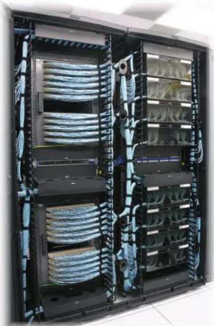
natural_image
Interior view of a server rack with multiple connected data racks and cable spools (no visible text or labels)Quick Reference
QuickNet™ Fiber Cabling Systems. 2
How to Use QuickNet ^™ Fiber Cabling Systems 3
QuickNet™ Fiber Cable Assembly Configurations 7
10G to 4G Migration. 8
How to Configure QuickNet ^TM Fiber Cable Assemblies....9
Reach Table 11
Guide for Measuring QuickNet ^TM Fiber Cable Assembly Lengths ..... 12
QuickNet™ Part Numbers 14
Selecting Fiber Optic Cassettes to support your QuickNet ^™ Fiber Cabling System 20
QuickNet ^™ Fiber Accessory Part Numbers 22
PANDUIT®
infrastructure for a connected world
APPLICATION GUIDE
QuickNet™ Fiber Cabling Systems
QuickNet™ Fiber Cabling Systems are available in a range of configurations and met the unique needs of data center projects of any scale.
This guide covers common considerations for using QuickNet™ Fiber Cabling Systems:
- Applications in the data center
- QuickNet™ Fiber Termination options and common configurations
- Specifying options, measuring for lengths and selecting QuickNet ^™ Fiber part numbers
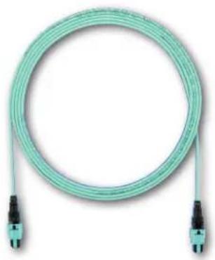
natural_image
Coiled light green fiber with two black connectors at ends (no text or symbols visible)QuickNet™ Fiber Applications in the Data Center
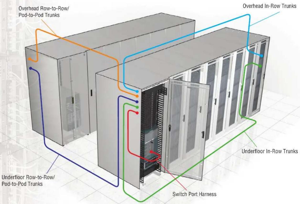
QuickNet™ products can be used for a wide variety of permanent link needs that are common in data center architectures such as Middle of Row (MoR) or End of Row (EoR) configurations, shown in Figure 1.
Figure 1 – Data Center Applications
How to Use QuickNet™ Fiber Cable Assemblies
The following sections illustrate and describe in greater detail how QuickNet ^™ Fiber Trunks, Interconnects, Harnesses, and Patch Cords, Cassettes and Patch Panels, are used in common data center cabling configurations.
Two-Connector Interconnect
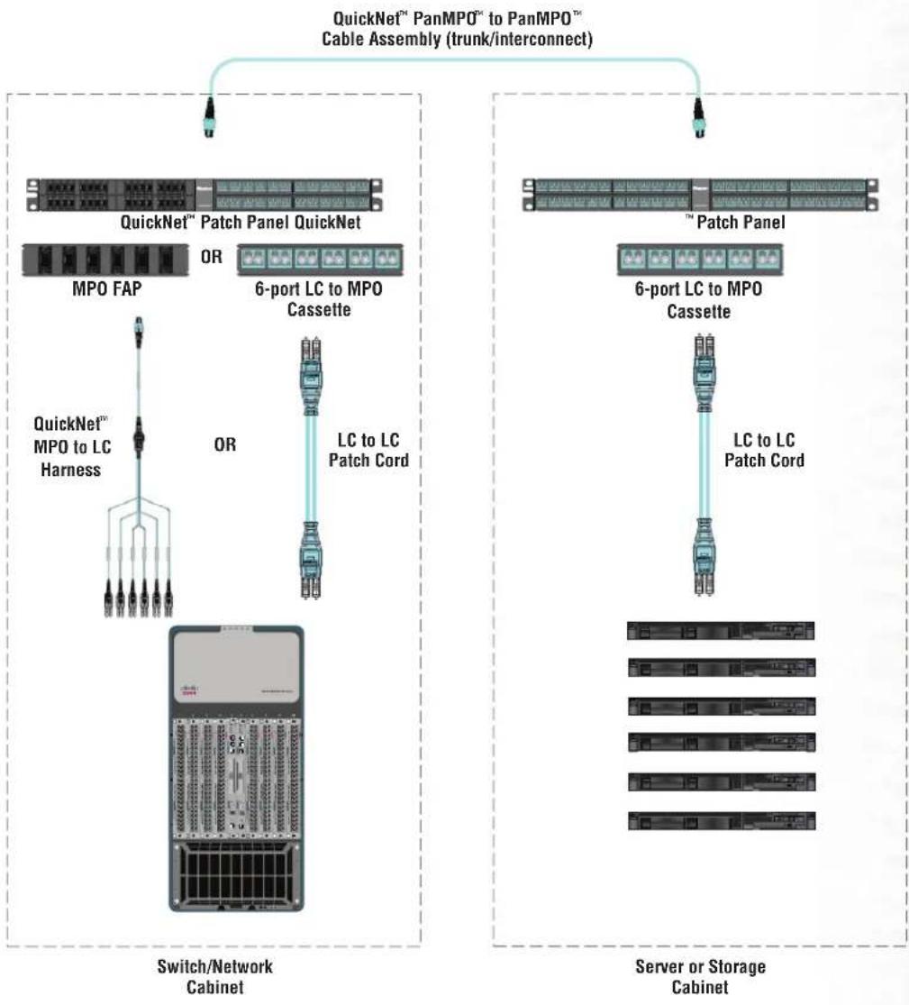
In this configuration, a permanent link is installed between QuickNet™ Patch Panels in the switch/network cabinet and the server or storage cabinets. The most common, flexible and upgradeable QuickNet™ Fiber solution is shown in Figure 2, below.
Figure 2 – Two-Connector Channel
flowchart
graph TD
    A["QuickNet™ PanMPO™ to PanMPO™ Cable Assembly (trunk/interconnect)"] --> B["QuickNet™ Patch Panel QuickNet"]
    B --> C["MPO FAP"]
    C --> D["QuickNet™ MPO to LC Harness"]
    D --> E["Switch/Network Cabinet"]
    A --> F["6-port LC to MPO Cassette"]
    F --> G["OR"]
    G --> H["LC to LC Patch Cord"]
    H --> I["Server or Storage Cabinet"]
    A --> J["6-port LC to MPO Cassette"]
    J --> K["OR"]
    K --> L["LC to LC Patch Cord"]
Four-Connector Cross Connect
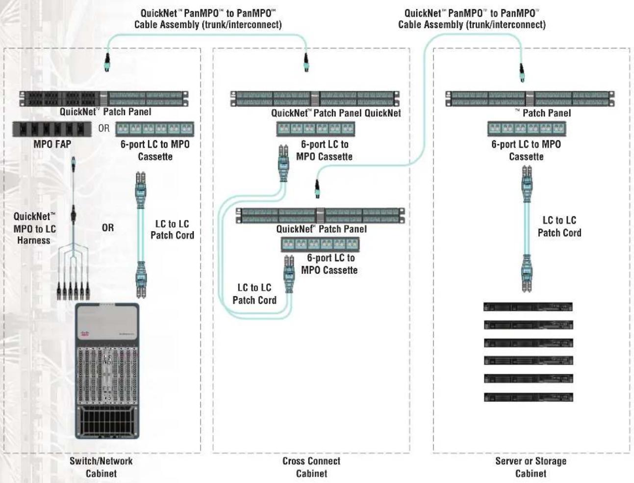
In this configuration, permanent links are installed between QuickNet™ Patch Panels in the switch/network cabinet and server or storage cabinets and a common cross connect cabinet or rack. In this scenario, any fiber from any switch port or server uplink can be routed to anywhere within the datacenter. This option allows for easy moves, adds, or changes. The most common, flexible, and upgradeable QuickNet™ Fiber solution is shown in Figure 3, below.
Figure 3 – Four-Connector Channel with Cross Connect
flowchart
graph TD
    A["Switch/Network Cabinet"] -->|QuickNet™ Patch Panel OR 6-port LC to MPO Cassette| B["Cross Connect Cabinet"]
    B -->|QuickNet™ Patch Panel QuickNet 6-port LC to MPO Cassette| C["Server or Storage Cabinet"]
    C -->|QuickNet™ Patch Panel 6-port LC to MPO Cassette| B
    B -->|LC to LC Patch Cord| D["Switch/Network Cabinet"]
    style A fill:#f9f,stroke:#333
    style B fill:#f9f,stroke:#333
    style C fill:#f9f,stroke:#333
Switch Port Equipment Harnesses
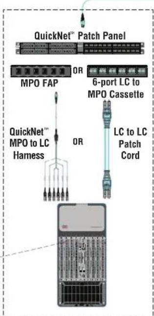
Switch port equipment harnesses are utilized in the switching area of the data center and to consolidate cabling. The LC to MPO harnesses connect six (6) or four (4) (depending on the switch blade layout), LC transceivers in the switch to a single MPO connector in an adapter panel installed in the switch cabinet to within 15m of the switch cabinet. This allows for consolidation of the switch ports into a single MPO connector. Panduit switch port equipment harnesses come in three different breakout arrangements shown below in Figure 4. Figure 5 illustrates the application.
Figure 4 – Harness Configurations

flowchart
graph LR
    A["Input Node"] --> B["Branch 1"]
    B --> C["Output Node 1"]
    B --> D["Branch 2"]
    D --> E["Output Node 2"]
    B --> F["Branch 3"]
    F --> G["Output Node 3"]
    B --> H["Branch 4"]
    H --> I["Output Node 4"]
    B --> J["Branch 5"]
    J --> K["Output Node 5"]
    B --> L["Branch 6"]
    L --> M["Output Node 6"]
    B --> N["Branch 7"]
    N --> O["Output Node 7"]
    B --> P["Branch 8"]
    P --> Q["Output Node 8"]
12 Fiber Harness with Equal Breakouts 12 Fiber Harness with Staggered Breakouts

natural_image
Pure electrical circuit lines without any symbols12 Fiber Harness with Staggered Breakouts with Two Equal Legs
Figure 5 – Switch Port Equipment Harnesses

Switch/Network Cabinet
HDQ Series High Density Cassettes
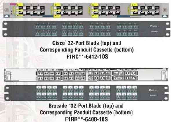
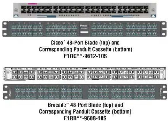
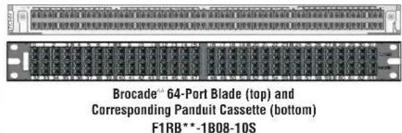
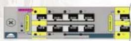
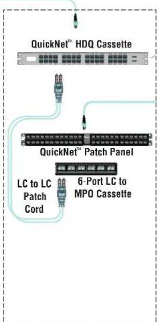
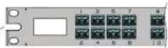
The QuickNet ^™ HDQ Series High Density Fiber Optic Cassettes can be used in high density network applications for cross connects to assist with switch port replication. These cassettes mirror 32-port and 48-port Cisco' blades and 32-port, 48-port and 64-port Brocade ^® blades as shown in Figure 6. These give the end user (at a cross connect area) the ability to visualize the blade port location when conducting moves, adds, or changes. Panduit also offers generic 48-port and 72-port HDQ cassettes.
Figure 6 – HDQ Example
**= Performance and fiber type
QuickNet™ PanMPO™ to PanMPO™ Cable Assembly (Trunk/Interconnect)
HDQ Series High Density Cassettes
flowchart
graph TD
    A["QuickNet™ HDQ Cassette"] --> B["QuickNet™ Patch Panel"]
    B --> C["6-Port LC to MPO Cassette"]
    B --> D["LC to LC Patch Cord"]
QuickNet™ PanMPO™ to PanMPO™ Cable Assembly to Server/Storage Cabinet
Switch/Network Cabinet Cross Connect Cabinet
*Cisco and Cisco Systems are registered trademarks of Cisco Technology, Inc.
**Brocade is a registered trademark of Brocade Communications Systems, Inc.
QuickNet™ Fiber Cable Assembly Options
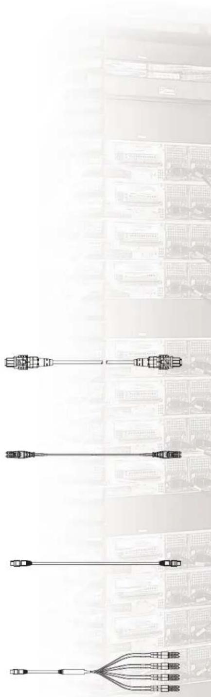
PanMPO Cable Assemblies
- Easily convert between male and female gender and between key-up and key-down polarity for 10G to 40G Ethernet installation
- Connector changes are made in the field as needed
• Available on trunks, harnesses and interconnects
Duplex LC to Duplex LC Patch Cord
- Patch cord with duplex LC connectors on both ends
• Typically used in cross-connect and as equipment patch cords in data centers - Connect to pre-terminated cassettes in main, horizontal, and equipment distribution
MPO to MPO Trunks/Interconnect
- Trunk or interconnect fiber cable with 12-fiber MPO connector(s) or LC connectors on each end
- Trunks offer greater mechanical protection (3x crush) than interconnects and are built with pulling eye. Preferred for lengths >30m/100 ft.
• Typically used in cabinet-to-cabinet permanent backbone links - Installs into QuickNet "Fiber Adapter Panels (FAP) or cassettes
MPO to LC Harness
- Harness cable with 12-fiber or 8-fiber LC connector(s) on one end and one MPO connector on the other end
• Typically used for connectivity between the switch in horizontal cabling - Installs into QuickNet™ MPO Patch Panels on one end and switch ports on the other end
flowchart
graph TD
    A["Switch"] --> B["Connector"]
    B --> C["Grid Server Rack"]
    C --> D["Server Rack"]
    style A fill:#f9f,stroke:#333
    style B fill:#ccf,stroke:#333
    style C fill:#cfc,stroke:#333
    style D fill:#fcc,stroke:#333
QuickNet™ Fiber Cable Assembly Configurations (continued)
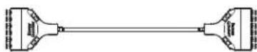
Cassette to Cassette Trunk
• Cassette of either 12 LC or 4, 6, 8 MPO connectors on each end
• Typically used for intra-row connectivity
• Factory tested as permanent link (does not require re-test in the field)
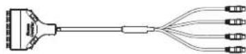
Cassette to MPO Trunk
- Cassette of either 12 LC or 4, 6, 8 MPO connectors on one end to discrete connectors on the other end.
• Typically used for inter-row connectivity
Cassette to LC Trunk
- Cassette of either 12 LC or 4, 6, 8 MPO connectors on one end to discrete connectors on the other end.
• Typically used for inter-row connectivity
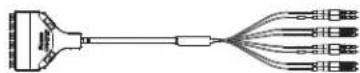
10G to 40G migration
PanMPO™ Connector makes 10G to 40G migration easy. Discover how easy here: www.panduit.com/panmpo
10G Method A with PanMPO

flowchart
graph LR
    A["A-B Patch Cord"] --> B["Method A Female to Female PanMPO Trunk"]
    B --> C["Pins Retracted"]
    C --> D["A-A Patch Cord"]
    D --> E["Port 1"]
    D --> F["Port 2"]
    D --> G["Port 3"]
    D --> H["Port 4"]
40G Method B with PanMPO

flowchart
graph LR
    A["40GBASE-SR4 QSFP+"] --> B["Method B Female to Female MPO Patch Cord"]
    B --> C["Method B Male to Male PanMPO Trunk"]
    C --> D["Method B Female to Female MPO Patch Cord"]
    D --> E["40GBASE-SR4 QSFP+"]
    note1["40GBASE-SR4 QSFP+"] --> A
    note2["Pins Extended and polarity flip on one end"] --> C
Panduit recommends the use of Method B polarity for 40G multimode parallel fiber solutions. Method B (Key Up to Key Up array connectivity) is widely used throughout the industry and is discussed in TIA-568-C.1. Method B array connectivity allows for the same equipment patch cords to be used whether the channel is comprised of the LC based 10GBASE-SR technology using array solutions in the horizontal cabling infrastructure or the MPO based 40GBASE-SR4 technology using array solutions throughout the infrastructure.
To assist with array polarity and gender, Panduit is offering the PanMPO which is a gender/polarity changeable MPO connector. PanMPO will allow for either male/female gender or key up/key down or key up/key up MPO trunk configurations.
How to Configure QuickNet™ Fiber Cable Assemblies
The QuickNet™ Fiber product family has a wide range of available configuration options from standard MPO to MPO cable assemblies to fully custom assemblies that are user-defined. In this section, each of the main configuration options for QuickNet™ Fiber are explained and typical considerations for data center applications are covered.
Fiber Type
The fiber type selected in the assembly indicates the maximum data rate that will be supported.
Cable choices:
- OS1/OS2 (Singlemode)
• OM3
- OM4
Laser optimized multimode fibers OM3, OM4 exceed domestic and international standards for optical fiber and support a diverse set of legacy and contemporary applications including Ethernet and Fibre Channel among many others. For 10GbE applications, the following link lengths are supported:
- OS1/OS2: 10km
• OM3: 300m
- OM4: 400m
Cable color defines fiber media type:
- OS1/OS2: Yellow
• OM3: Aqua
- OM4: Aqua
Note: Additional guidance on the supported link reaches for data center applications with various channel insertion losses is available at www.panduit.com.
Fiber Count
Fiber count choices:
Interconnects
• 12-fiber
- 24-fiber
Harnesses
• 8-fiber
- 8-fiber QSFP to SFP+
• 12-fiber
Trunks
• 12-fiber
- 24-fiber
• 48-fiber
- 72-fiber
Cable Flame Rating
Cable flame rating choices are:
- Low Smoke Zero Halogen (LSZH), tested to IEC 60332, 60754, and 610345
• Optical Fiber Non-Conductive Plenum (OFNP), tested to NFPA 262
• Optical Fiber Non-Conductive Riser (OFNR), tested to UL-1666
Low Smoke Zero Halogen (LSZH) rated cable is jacketed with compounds that emit limited smoke and no halogen when exposed to high heat sources. It is the preferred jacket in EMEA.
Plenum (OFNP) is jacketed with a fire-retardant plastic.
Riser (OFNR) cables contain no electrically conductive materials. These are used in a contained area, usually a vertical shaft.
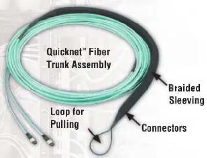
Figure 8 – Pulling Eye Option
Trunk Type and Terminations
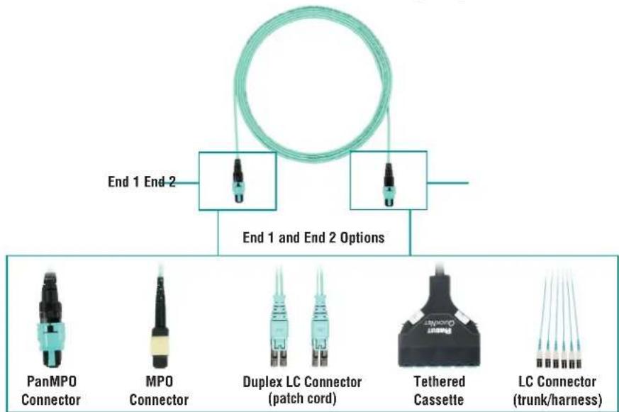
Both ends of a QuickNet ^™ Fiber cable assembly include one of a range of factory termination options – each end can be different and are selected based upon the desired application of the trunk or harness within the data center.
Termination choices are:
- Duplex LC to Duplex LC
- PanMPO to PanMPO
- PanMPO to LC
- MPO to MPO
- MPO to LC
- Cassette to Cassette
• Cassette to MPO/Duplex LC
Insertion Loss is the amount of power lost at each mated pair of connectors. Standard maximum insertion loss per connector pair:
- Multimode PanMPO to PanMPO: 0.50dB
• Multimode MPO to MPO: 0.50dB - Multimode
• Singlemode MPO to MPO: 0.75dB - Singlemode LC to LC: 0.35dB
LC to LC: 0.25dB
Optimized insertion loss per connector pair:
• Multimode PanMPO to PanMPO: 0.35dB
• Multimode MPO to MPO: 0.35dB
• Multimode LC to LC: 0.15dB
Assembly Options
Options include:
- No Pulling Eye
- Pulling eye on one end (as shown in Figure 8)
- Pulling eye on both ends
A pulling eye is a loop of braided sleeve material that is applied to one or both ends of the QuickNet™ Trunk Assembly, and is used to pull the cable in the pathways at deployment.
Labeling
All QuickNet ^™ Fiber Cable Assemblies have an assembly label on each end which includes the part number, length, and a serialized quality control number. Label example shown in Figure 9.
Reach Table
Panduit ^® laser optimized OM3, OM4 multimode fibers meet domestic and international standards. Signature Core ^™ exceeds domestic and international standards for optical fiber. This includes TIA-492AAAB, TIA-492AAAC, TIA-492AAAD and IEC 60793-2-10 and support a diverse set of legacy and contemporary applications including Ethernet, Fibre Channel, Infiniband ^™ and FICON (Fiber Connection) among others.
| Application | Connectivity Budget (dB) | ||
| 1.5 | |||
| Fiber Category | |||
| OM3 OM4 | SigCore | ||
| Maximum Channel Length (m) | |||
| 10 Gb/s Ethernet (10GBASE-SR) 300 400 550 | |||
| 40 and 100 Gb/s Ethernet (40/100GBASE-SR4/10) 100 125 | 165 | ||
| 4G Fibre Channel 380 400 500 | |||
| 8G Fibre Channel 150 190 250 | |||
| 16G Fibre Channel 100 125 200 | |||
| Cisco 40G BiDi 100 135 200 | |||
| 100 Gb/s Ethernet (4x25) (100GBASE-SR4) 70 100 125 | |||
Note: Maximum channel lengths will increase or decrease based on higher or lower loss budgets.
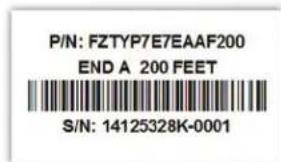
Figure 9 – Labels
Guide for Measuring QuickNet™ Fiber Cable Assembly Lengths
Proper measuring for QuickNet ^™ Fiber Cable Assembly lengths is straightforward but does require some detailed information about the data center layout. For the most accurate length measurements, it is best to work from layout drawings and know the specific equipment to be used, the cabinet dimensions, and the desired positions in the cabinets of patch panels and equipment.
The illustration below shows a typical data center link and the sections that must be considered to properly measure for QuickNet ^™ Fiber Cable Assembly lengths. This example shows an overhead in-row installation. For other configurations, adjust accordingly. (For example, with underfloor configurations, measure down from the panels to the pathway).
Recommended Steps for Measuring QuickNet™ Fiber Cable Assembly Lengths:
- Calculate or measure the length of each section of the link.
a. Harness length: A1 + A2
b. Horizontal cable length: B + C + D
- Round the total upward to the nearest foot to get the minimum QuickNet ^™ Fiber Cable Assembly length.
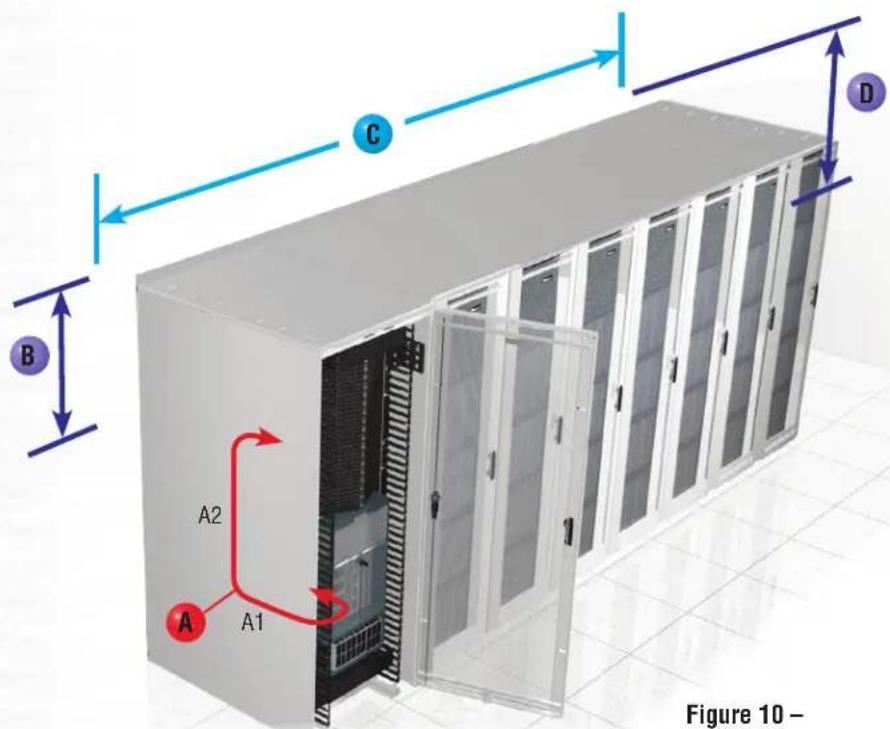
Figure 10 – End of Row Link
Link Sections and Guide for Measuring:
A In-cabinet length: The total length of the cable inside the cabinet (A1 + A2).
A1 – Horizontal distance from switch face to vertical manager – Panduit recommends 1m breakout or stagger to
allow for cable routing and management.
A2 - Distance from vertical manager to patch panel in cabinet - this can vary depending upon where the patch
panel is located within the cabinet.
B Patch panel-to-pathway length: The distance from the patch panel in cabinet to the cable pathway.
C Length along pathway: The total distance along the pathway between the cabinet entry/exit points.
D Pathway-to-patch panel length: Similar to B.
Length Measurement Example
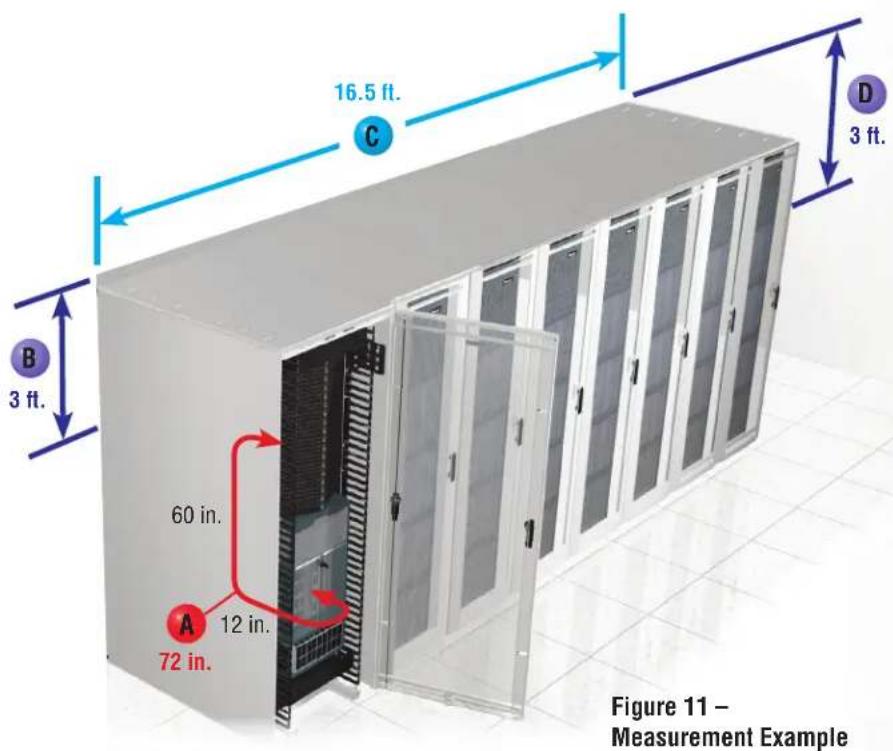
Example: In-cabinet length: 72 in. (12 in. + 60 in.)
A1 – Distance from switch plate to vertical manager = 12 in. A2 – Distance from vertical manager to patch panel = 60 in.
B Patch panel-to-pathway length: 3 ft.
C Length along pathway: 16.5 ft. (assuming seven 24 in. wide server cabinets and cable exit on far side of 30 in. wide network cabinet = (7 × 2 ft.) + 30 in.)
D Pathway-to-patch panel length: 3 ft.
Total harness length = (12 in. + 60 in.) = 72 in. = 6 ft.
Total horizontal cable length = (3 ft. + 16.5 ft. + 3 ft.) = 22.5 ft. = 23 ft.
Tips for Measuring Lengths:
- The specified length of a QuickNet™ Fiber Cable Assembly is the distance as measured from the front of the connector on one end to the front of the connector on the other end. Other than a nominal manufacturing tolerance there is no additional length built into a QuickNet™ Fiber Cable Assembly.
- Remember to account for any turns or obstructions in the pathway that may lead to additional length needed (for example, ducting, support posts, etc.).
- Cable assembly bend radius limits must be taken into consideration, especially for multiple turns within cabinets or as the cable assembly transitions to or from the pathways, and may require additional length of the assembly.
QuickNet™ Part Numbers
QuickNet™ Fiber Cable Assemblies – Part Numbers
Opti-Core® Fiber Optic Patch Cords and Pigtails
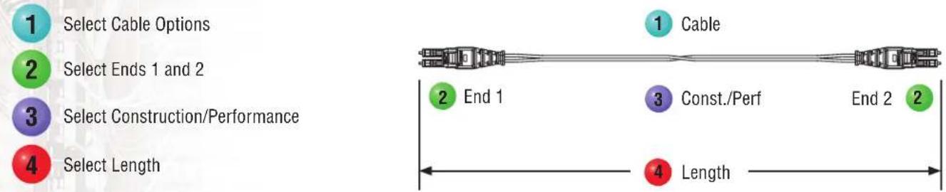
Steps to Select:
flowchart
graph LR
    A["Select Cable Options"] --> B["Select Ends 1 and 2"]
    B --> C["Select Construction/Performance"]
    C --> D["Select Length"]

    E["Cable"] --> F["End 1"]
    F --> G["Const./Perf"]
    G --> H["End 2"]
    H --> I["Length"]
flowchart
graph TD
    A["Fiber"] --> B["Fiber Type"]
    A --> C["Fiber Count"]
    A --> D["Cable Type"]
    A --> E["Jacket Type"]
    B --> F["9 = OS1/OS2 9/125μm\nX = OM3 50/125μm\nZ = OM4 50/125μm"]
    C --> G["1 = 1-fibers\n2 = 2-fibers"]
    D --> H["B = 900um buffer\n(pigtail only)\ne = 1.6mm\n(standard for LC)\n3 = 3.0mm\n(standard for SC)"]
    E --> I["L = Low Smoke Zero\nHalogen (LSZH)\nR = Optical Fiber\nNonconductive\nRiser (OFNR)\nP = Optical Fiber\nNonconductive\nPlenum (OFNP)"]

    J["Cable"] --> K["Q = Push-Pull LC duplex\nS = SC duplex"]
    K --> L["Connector Type End 1"]
    L --> M["1 = LC Simplex\n3 = SC Simplex\nA = SC-APC\nL = LC duplex\nQ = Push-Pull LC duplex\nS = SC duplex"]
    M --> N["Connector Variant"]
    N --> O["1 = Push-Pull\n(LC duplex only)\nN = No Variant"]
    O --> P["Connector Type End 2"]
    P --> Q["1 = LC Simplex\n3 = SC Simplex\nA = SC-APC\nL = LC duplex\nN = None (pigtail)\nQ = Push-Pull LC duplex\nS = SC duplex"]

    R["End 1"] --> S["Q"]
    S --> T["S"]
    T --> U["Performance/Polarity\nS = Standard IL/Standard Polarity\nO = Optimized IL/Standard Polarity"]
    U --> V["Connector Variant"]
    V --> W["1 = Push-Pull\n(LC duplex only)\nN = No Variant"]

    X["End 2"] --> Y["Q"]
    Y --> Z["S"]
    Z --> AA["Const./Perf"]
    AA --> AB["Other"]
    AB --> AC["Unit"]
    AC --> AD["M"]
    AD --> AE["0"]
    AD --> AF["0"]
    AD --> AG["5"]

    AH["Length"] --> AI["1m to 50m (001-050)\n1m increments"]
    AI --> AJ["Unit of Length\nM = Meters"]
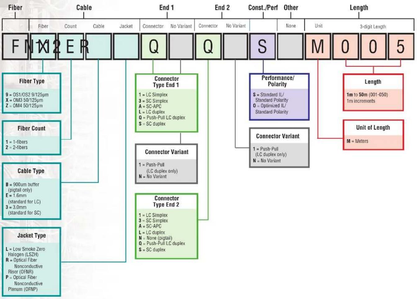
Above part number FX2ERQ1Q1SNM005: Fiber, OM3 50/125μm 2-fiber 1.6mm riser, LC push-pull connector to LC push-pull connector, standard IL, 5m.
QuickNet™ Fiber Cable Assemblies – Part Numbers
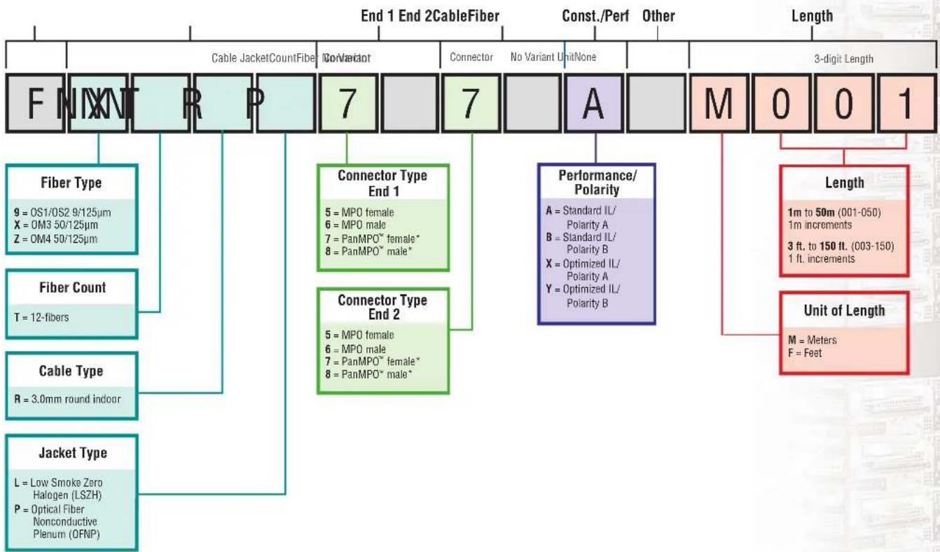
QuickNet™ Round Interconnect Cable Assemblies
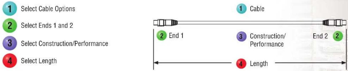
Steps to Select:
flowchart
graph LR
    A["1 Select Cable Options"] --> B["2 Select Ends 1 and 2"]
    B --> C["3 Select Construction/Performance"]
    C --> D["4 Select Length"]

    E["1 Cable"] --> F["2 End 1"]
    F --> G["3 Construction/Performance"]
    G --> H["End 2"]
    H --> I["4 Length"]
flowchart
graph TD
    A["F N X N T R P"] --> B["Fiber Type"]
    A --> C["Fiber Count"]
    A --> D["Cable Type"]
    A --> E["Jacket Type"]
    B --> F["9 = OS1/OS2 9/125μm\nX = OM3 50/125μm\nZ = OM4 50/125μm"]
    C --> G["T = 12-fibers"]
    D --> H["R = 3.0mm round indoor"]
    E --> I["L = Low Smoke Zero\nHalogen (LSZH)\nP = Optical Fiber\nNonconductive\nPlenum (OFNP)"]
    J["7"] --> K["Connector Type End 1"]
    J --> L["Connector Type End 2"]
    K --> M["5 = MPO female\n6 = MPO male\n7 = PanMPO™ female*\n8 = PanMPO™ male*"]
    L --> N["5 = MPO female\n6 = MPO male\n7 = PanMPO™ female*\n8 = PanMPO™ male*"]
    O["7"] --> P["Connector Type"]
    O --> Q["Connector"]
    P --> R["A"]
    Q --> S["A"]
    R --> T["M"]
    S --> U["M"]
    T --> V["0"]
    U --> W["0"]
    V --> X["1"]
    W --> Y["0"]
    X --> Z["3-digit Length"]
    Y --> AA["Length"]
    Z --> AB["Unit of Length"]
    AA --> AC["1m to 50m (001-050)\n1m increments\n3 ft. to 150 ft. (003-150)\n1 ft. increments"]
    AB --> AD["M = Meters\nF = Feet"]
    style A fill:#f9f,stroke:#333
    style B fill:#ccf,stroke:#333
    style C fill:#ccf,stroke:#333
    style D fill:#ccf,stroke:#333
    style E fill:#ccf,stroke:#333
    style F fill:#cfc,stroke:#333
    style G fill:#cfc,stroke:#333
    style H fill:#cfc,stroke:#333
    style I fill:#cfc,stroke:#333
    style J fill:#cfc,stroke:#333
    style K fill:#cfc,stroke:#333
    style L fill:#cfc,stroke:#333
    style M fill:#cfc,stroke:#333
    style N fill:#cfc,stroke:#333
    style O fill:#cfc,stroke:#333
    style P fill:#cfc,stroke:#333
    style Q fill:#cfc,stroke:#333
    style R fill:#cfc,stroke:#333
    style S fill:#cfc,stroke:#333
    style T fill:#cfc,stroke:#333
    style U fill:#cfc,stroke:#333
    style V fill:#cfc,stroke:#333
    style W fill:#cfc,stroke:#333
    style X fill:#cfc,stroke:#333
Above part number FXTRP7N7NANM001: Fiber, OM3 50/125μm 12-fiber 3.0mm round indoor OFNP cable with PanMPO™ female connectors with no variants on both ends, Polarity A – standard IL, 1m in length.
*PanMPO™ option is only available with multimode (OM3/OM4) assemblies.
QuickNet™ Fiber Cable Assemblies – Part Numbers (cont.)
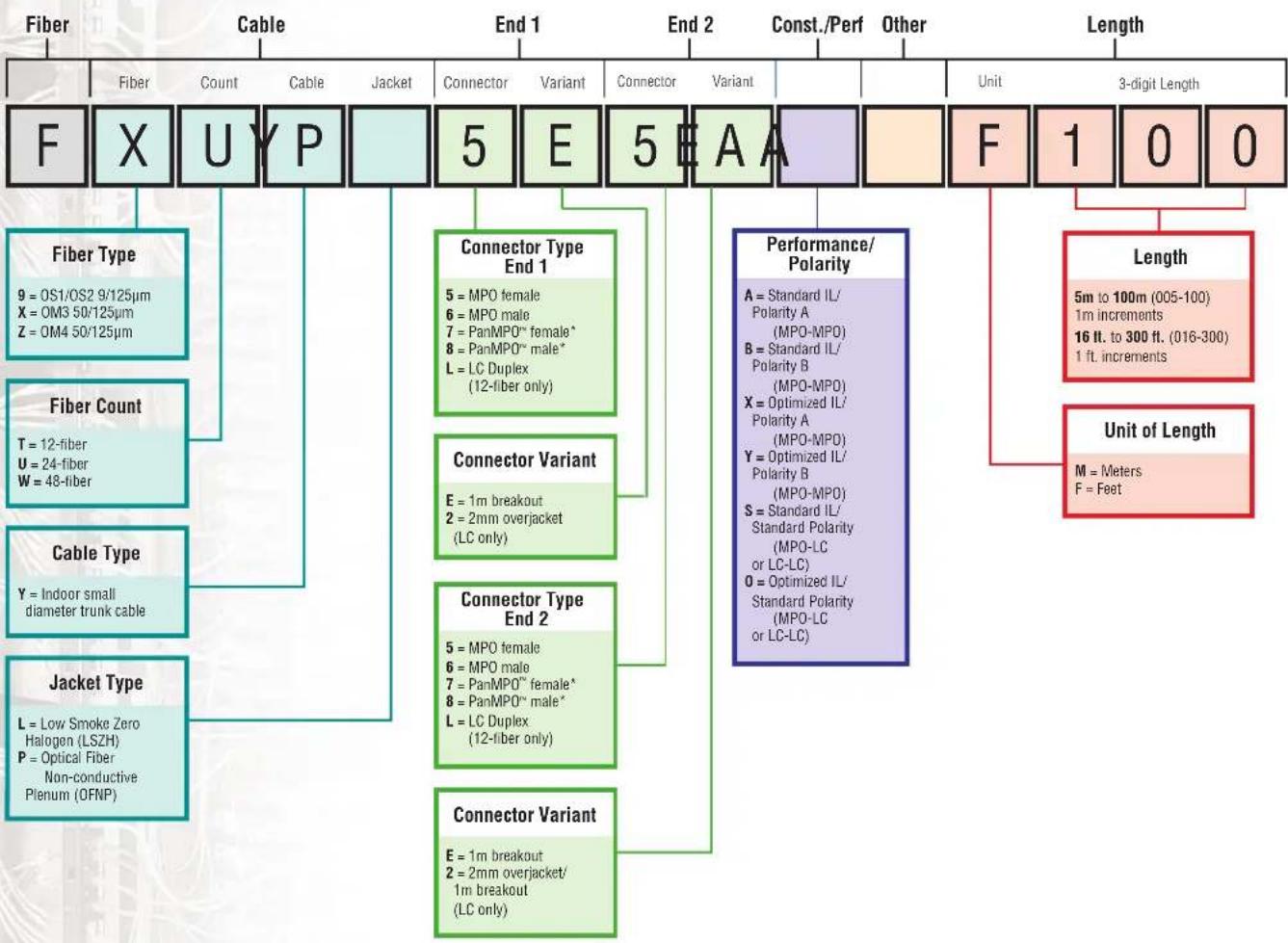
QuickNet™ Small Diameter Trunk Cable Assemblies
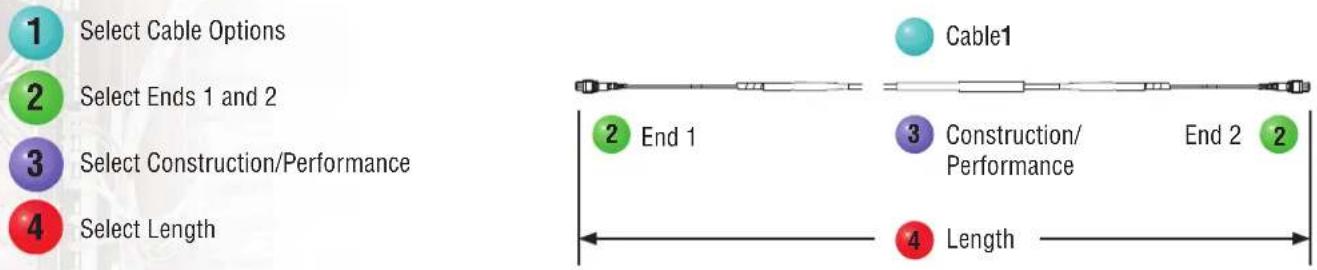
Steps to Select:
flowchart
graph LR
    A["Select Cable Options"] --> B["Select Ends 1 and 2"]
    B --> C["Select Construction/Performance"]
    C --> D["Select Length"]

    E["Cable1"] --> F["End 1"]
    F --> G["Construction/Performance"]
    G --> H["End 2"]
    H --> I["Length"]
flowchart
graph TD
    A["Fiber Type"] --> B["9 = OS1/OS2 9/125μm"]
    A --> C["X = OM3 50/125μm"]
    A --> D["Z = OM4 50/125μm"]
    E["Fiber Count"] --> F["T = 12-fiber"]
    E --> G["U = 24-fiber"]
    E --> H["W = 48-fiber"]
    I["Cable Type"] --> J["Y = Indoor small diameter trunk cable"]
    K["Jacket Type"] --> L["L = Low Smoke Zero Halogen (LSZH)"]
    K --> M["P = Optical Fiber Non-conductive Plenum (OFNP)"]

    N["Fiber"] --> O["X"]
    N --> P["UY"]
    N --> Q["YP"]

    R["Fiber"] --> S["End 1"]
    R --> T["End 2"]
    R --> U["End 3"]

    V["Fiber"] --> W["E"]
    V --> X["E"]
    V --> Y["A"]

    Z["Fiber"] --> AA["End 1"]
    Z --> AB["End 2"]
    Z --> AC["End 3"]

    AD["Fiber"] --> AE["Performance/Polarity"]
    AD --> AF["Length"]
    AD --> AG["Unit of Length"]

    AH["Connector Type"] --> AI["End 1"]
    AH --> AJ["End 2"]

    AK["Connector Variant"] --> AL["End 1"]
    AK --> AM["End 2"]

    AN["Connector Variant"] --> AO["End 2"]

    AP["Connector Variant"] --> AQ["End 2"]

    AR["Performance/Polarity"] --> AS["A = Standard IL/Polarity A (MPO-MPO)"]
    AR --> AT["B = Standard IL/Polarity B (MPO-MPO)"]
    AR --> AU["X = Optimized IL/Polarity A (MPO-MPO)"]
    AR --> AV["Y = Optimized IL/Polarity B (MPO-MPO)"]
    AR --> AW["S = Standard IL/Standard Polarity (MPO-LC or LC-LC)"]
    AR --> AX["O = Optimized IL/Standard Polarity (MPO-LC or LC-LC)"]
Above part number FXUYP5E5EAAF100: Fiber, OM3 50/125μm 24-fiber indoor small diameter trunk plenum cable with MPO female connectors on both ends with 1m breakout variant, Polarity A-standard IL, Pulling eye on End 1, 100 ft. in length.
Longer lengths are available.
*PanMPO™ option is only available with multimode (OM3/OM4) assemblies.
QuickNet™ Fiber Cable Assemblies – Part Numbers
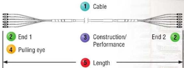
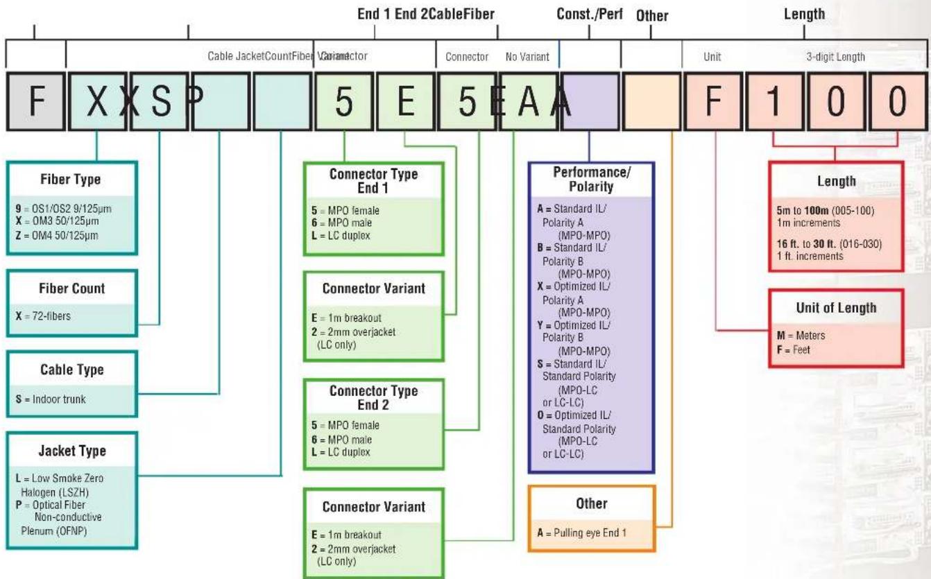
QuickNet™ Trunk Cable Assemblies
Steps to Select:

Select Cable Options

Select Ends 1 and 2

Select Construction/Performance

Select Pulling Eye Option

Select Length
flowchart
graph LR
    A["1 Cable"] --> B["2 End 1"]
    B --> C["4 Pulling eye"]
    C --> D["3 Construction/Performance"]
    D --> E["End 2"]
    E --> F["5 Length"]
flowchart
graph TD
    A["End 1 End 2 CableFiber"] --> B["F"]
    A --> C["X"]
    A --> D["S"]
    A --> E["P"]
    A --> F["5"]
    A --> G["E"]
    A --> H["5"]
    A --> I["A"]
    A --> J["E"]
    K["Const./Perf"] --> L["Connector Type End 1"]
    K --> M["Connector Variant"]
    K --> N["Connector Type End 2"]
    K --> O["Connector Variant"]
    K --> P["Performance/Polarity"]
    K --> Q["Length"]
    K --> R["Unit of Length"]
    K --> S["Other"]

    B --> T["Fiber Type"]
    B --> U["X = 72-fibers"]
    B --> V["Cable Type"]
    B --> W["Jacket Type"]

    C --> X["Fiber Count"]
    C --> Y["S = Indoor trunk"]

    D --> Z["Fiber Count"]
    D --> AA["Cable Type"]
    D --> AB["Jacket Type"]

    E --> AC["Fiber Count"]
    E --> AD["X = 72-fibers"]

    F --> AE["Fiber Count"]
    F --> AF["Cable Type"]
    F --> AG["Jacket Type"]

    G --> AH["Fiber Count"]
    G --> AI["X = 72-fibers"]

    H --> AJ["Fiber Count"]
    H --> AK["Cable Type"]
    H --> AL["Jacket Type"]

    I --> AM["Fiber Count"]
    I --> AN["X = 72-fibers"]

    J --> AO["Fiber Count"]
    J --> AP["Cable Type"]
    J --> AQ["Jacket Type"]

    K --> AR["Fiber Count"]
    K --> AS["X = 72-fibers"]

    L --> AT["Fiber Count"]
    L --> AU["X = 72-fibers"]

    M --> AV["Fiber Count"]
    M --> AW["X = 72-fibers"]

    N --> AX["Fiber Count"]
    N --> AY["X = 72-fibers"]

    O --> AZ["Fiber Count"]
    O --> BA["X = 72-fibers"]

    P --> BB["Fiber Count"]
    P --> BC["X = 72-fibers"]

    Q --> BD["Fiber Count"]
    Q --> BE["X = 72-fibers"]

    AR --> BF["Fiber Count"]
    AR --> BG["X = 72-fibers"]

    AS --> BH["Fiber Count"]
    AS --> BI["X = 72-fibers"]

    AT --> BJ["Fiber Count"]
    AT --> BK["X = 72-fibers"]

    AU --> BL["Fiber Count"]
    AU --> BM["X = 72-fibers"]

    AV --> BN["Fiber Count"]
    AV --> BO["X = 72-fibers"]

    AW --> BP["Fiber Count"]
    AW --> BQ["X = 72-fibers"]

    AX --> BR["Fiber Count"]
    AX --> BS["X = 72-fibers"]

    AU --> BT["Fiber Count"]
    AU --> BU["X = 72-fibers"]

    AV --> BV["Fiber Count"]
    AV --> BW["X = 72-fibers"]

    BW --> BX["Fiber Count"]
    BW --> BY["X = 72-fibers"]

    AX --> BZ["Fiber Count"]
    AX --> CA["X = 72-fibers"]

    BZ --> CB["Fiber Count"]
    BZ --> CC["X = 72-fibers"]

    AD --> CD["Fiber Count"]
    AD --> CE["X = 72-fibers"]

    BE --> CF["Fiber Count"]
    BE --> CG["X = 72-fibers"]

    BE --> CH["Fiber Count"]
    BE --> CI["X = 72-fibers"]

    BE --> CJ["Fiber Count"]

    CA --> CK["Fiber Count"]
    CA --> CL["X = 72-fibers"]

    BE --> CD
    BE --> DB
    BE --> DC

    BC --> DE["Fiber Count"]
    BC --> DF["X = 72-fibers"]

    BE --> DG
    BE --> DE
Above part number FXXSP5E5EAAF100: Fiber, OM3 50/125μm 72-fiber indoor trunk plenum cable with MPO female to MPO female connectors with 1m breakout, Polarity A-standard IL, pulling eye on End 1, 100 ft. in length.
QuickNet™ Fiber Cable Assemblies – Part Numbers (cont.)
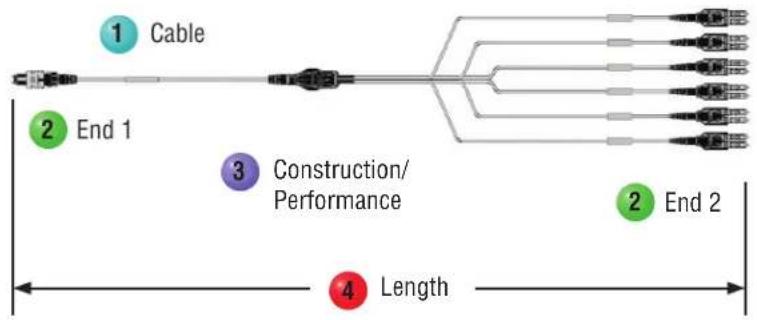
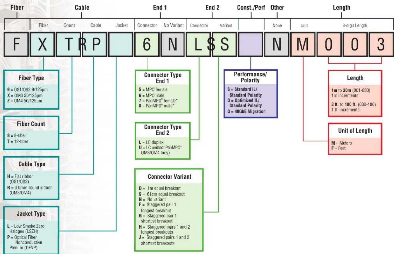
QuickNet™ Harness and Staggered Harness Cable Assemblies
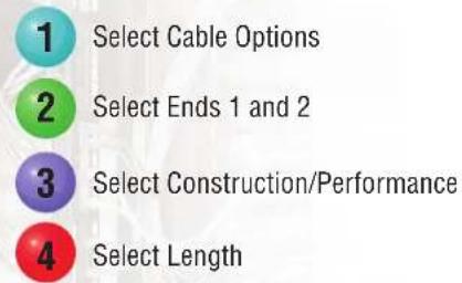
Steps to Select:
flowchart
graph LR
    A["Cable"] --> B["End 1"]
    B --> C["Construction/Performance"]
    C --> D["Length"]
    style A fill:#f9f,stroke:#333
    style B fill:#ccf,stroke:#333
    style C fill:#cfc,stroke:#333
    style D fill:#fcc,stroke:#333
flowchart
graph TD
    A["Fiber"] --> B["X"]
    B --> C["TRP"]
    C --> D["6"]
    D --> E["N"]
    E --> F["L$S"]
    F --> G["N"]
    G --> H["M"]
    H --> I["0"]
    I --> J["0"]
    J --> K["3"]

    L["Fiber Type"] --> M["9 = OS1/OS2 9/125µm\nX = OM3 50/125µm\nZ = OM4 50/125µm"]
    N["Fiber Count"] --> O["8 = 8-fiber\nT = 12-fiber"]
    P["Cable Type"] --> Q["H = Flat ribbon\n(OS1/OS2)\nR = 3.0mm round indoor\n(OM3/OM4)"]
    R["Jacket Type"] --> S["L = Low Smoke Zero\nHalogen (LSZH)\nP = Optical Fiber\nNonconductive\nPlenum (OFNP)"]

    T["Connector Type End 1"] --> U["5 = MPO female\n6 = MPO male\n7 = PanMPO™ female*\n8 = PanMPO™ male*"]
    V["Connector Type End 2"] --> W["L = LC duplex\nU = LC uniboot PanMPO™\nOM3/OM4 only"]
    X["Connector Variant"] --> Y["D = 1m equal breakout\nS = 61cm equal breakout\nN = No variant\nF = Staggered pair 1\nlongest breakout\nG = Staggered pair 1\nshortest breakout\nH = Staggered pairs 1 and 2\nlongest breakouts\nJ = Staggered pairs 1 and 2\nshortest breakouts"]

    Z["Performance/Polarity"] --> AA["S = Standard IL/\nStandard Polarity\nO = Optimized IL/\nStandard Polarity\nQ = 40GbE Migration"]

    AB["Unit of Length"] --> AC["Length: 1m to 30m (001-030)\n1m increments\n3 ft. to 100 ft. (030-100)\n1 ft increments"]

    AD["Length: M = Meters\nF = Feet"] --> AE["Unit of Length"]

    AF["Const./Perf"] --> AG["None"]
    AH["Other"] --> AI["Unit"]

    AJ["3-digit Length"] --> AK["Length: 1m to 30m (001-030)\n1m increments\n3 ft. to 100 ft. (030-100)\n1 ft increments"]
Above part number FXTRP6NLSSNM003: Fiber, OM3 50/125μm 12-fiber 3.0mm round OFNP with MPO male connectors with no variant on End 1 and LC Duplex connectors with 61cm equal breakout on End 2, Standard IL-straight thru (MPO Discrete), 3m in length.
*PanMPO™ option is only available with multimode (OM3/OM4) assemblies.
Note: Harness and Staggered Harness Cable Assemblies are not intended to be used for breakout or data rate migration solutions.
QuickNet™ Fiber Cable Assemblies – Part Numbers
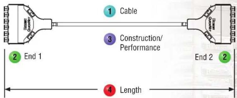
QuickNet™ SFQ Trunk Cable Assemblies
Steps to Select:
1 Select Cable Options
2 Select Ends 1 and 2
3 Select Construction/Performance
4 Select Length
flowchart
graph TD
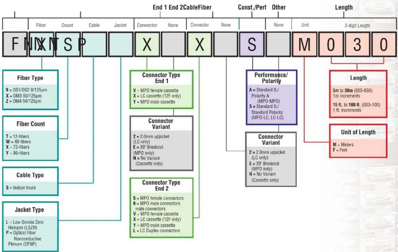
    A["F N X N S P"] --> B["Fiber Type"]
    A --> C["Fiber Count"]
    A --> D["Cable Type"]
    A --> E["Jacket Type"]
    B --> F["9 = OS1/OS2 9/125μm\nX = OM3 50/125μm\nZ = OM4 50/125μm"]
    C --> G["T = 12-fibers\nW = 48-fibers\nX = 72-fibers\nY = 96-fibers"]
    D --> H["S = Indoor trunk"]
    E --> I["L = Low Smoke Zero\nHalogen (LSZH)\nP = Optical Fiber\nNonconductive\nPlenum (OFNP)"]
    F --> J["Connector Type End 1"]
    G --> K["Connector Variant"]
    H --> L["Connector Type End 2"]
    I --> M["Performance/Polarity"]
    J --> N["Connector Variant"]
    K --> O["Length"]
    L --> P["Unit of Length"]
    M --> Q["Const./Perf"]
    N --> R["Other"]
    O --> S["3-digit Length"]
    P --> T["M = Meters\nF = Feet"]
Above part number FXTSPXNXNSNM030: Fiber, OM3 50/125μm 12-fiber indoor trunk OFNP cable with LC Cassettes on each end with no variant, Polarity A standard IL, 30m in length.
*PanMPO™ option is only available with multimode (OM3/OM4) assemblies.
Selecting Fiber Optic Cassettes to support your QuickNet™ Fiber Cabling System
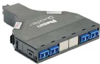
SFQ, Opticom ^3 , and HDQ cassettes are available in OS1/OS2, OM3, OM4, and Signature Core
Modular Cassettes SFQ
- Streamlined and flexible connectivity solution for use in main, horizontal and equipment distribution areas
- Snap-in rear mount allows for easy installation into an open rack
- Pre-terminated LC, SC and MTP* adapters for quick deployment
- Offered in a wide range of performance and polarity configurations (including 4-to-1 break-out)
- SFQ cassette part numbers begin with FQ and FQ3 (4-to-1 break-out)
- SFQ cassettes snap-in QuickNet ^* angled (QAPP24BL) and flat (QPP24BL) patch panels
OptiCom®
- Flexible connectivity solution for use in main, horizontal and equipment distribution areas
- Snap-in front mount allows for easy installation into adapter patch panels or cassette enclosures
- Pre-terminated LC, SC and MTP* adapters for quick deployment
- Offered in a wide range of performance and polarity configurations (including 4-to-1 break-out)
- OptiCom ^ cassette part numbers begin with FC2 and FC3 (4-to-1 break-out)
- OptiCom ^® cassettes snap-in OptiCom ^® fiber adapter patch panels (CFAPPBL1) and QuickNet ^® Fiber Cassette Enclosures (FCE1U, FRME1U, FMT1)
High Density HDQ
- Fixed port connectivity solution for use in main, horizontal and equipment distribution areas
- Robust fixed port design enables high reliability
• High density, up to 144 fibers per RU - Configured to replicate ports on popular SAN blades from Cisco‡ and Brocade‡‡
- Mounts directly to standard 19" rack rails
- Pre-terminated LC adapters on the front and MTP* adapters on the back enable quick deployments
- Offered in a wide range of performance and polarity configurations
• HDQ cassette part numbers begin with F1R (flat) and F1A (angled)
†Cisco and Cisco Systems are registered trademarks of Cisco Technology, Inc. ‡ Brocade is a registered trademark of Brocade Communications Systems, Inc. * MTP is a registered trademark of US Conec Ltd.
natural_image
Exterior view of a black wireless device labeled 'QUICKENET' with blue connectors (no additional text or symbols visible)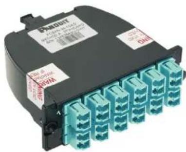
natural_image
Exterior view of a network device with multiple Ethernet ports (no text or symbols visible)QuickNet™ SFQ Series MTP\* Fiber Optic Cassettes
Character
Example
1
F
23456
QXO-1


1 - Fiber Product
F = Fiber
2 - Product Type
Q = QuickNet
3 - Fiber Type
9 = OS1/OS2 9/125μm (available with standard loss only
X = OM3 10Gig 50/125μm
Z = OM4 10Gig 50/125μm
4 - Fiber Performance
N = Standard Loss (0.75dB Max. IL)
O = Optimized Cassette (0.5dB Max. IL)
5 - Dash
6, 7 - Fiber Count
06 = 6-fiber total
08 = 8-fiber total
12 = 12-fiber total
8 - Dash
9, 10 - Adapter Type
03 = Duplex SC Adapter (6-fiber only)
10 = Duplex LC Adapter (8 or 12-fiber only)
11, 12 - Polarity
AS = Method A, standard
AF = Modified Method A, lipped
B1 = Method B, B1 (1-1 array) B2 = Method B, B2 (1-12 array)
*B1 needs to be paired with B2
*B2 needs to be paired with B1
QuickNet™ Opticom® Fiber Optic Cassettes
Character
Example
1
F
2
C
3
2
4
z
5
0
6
-
7
2
8
4
9
-
10
1
11
0
12
A
13
s
1 - Fiber Product
F = Fiber
2 - Product
C = Cassette
3 - Generation
2 = Second generation
4 - Fiber Type
9 = OS1/OS2 9/125μm (available with standard loss only)
X = OM3 10Gig 50/125μm
Z = OM4 10Gig 50/125μm
5 - Fiber Performance
N = Standard Loss (0.75dB Max. IL)
O = Optimized Cassette (0.5dB Max. IL)
6 - Dash
7 - Numbers of Fibers
06 = 06-fiber total
12 = 12-fiber total
24 = 24-fiber total
9 - Dash
10 and 11 - Adapter Type
03 = Duplex SC Adapter
(6 or 12-fiber only)
10 = Duplex LC Adapter
(12 or 24-fiber only)
3S = Simplex SC Adapter
(6 or 12-fiber only)
12 and 13 – Polarity
AS = Method A, standard
AF = Modified Method A, pair flipped
B1 = Method B, B1 (1-1 array)
B2 = Method B, B2 (1-12 array)
*B1 needs to be paired with B2
^* B2 needs to be paired with B1
QuickNet™ Fiber Accessory Part Numbers
Common QuickNet™ Accessories
QuickNet™ Patch Panels:
- Designed to enable rapid installation
• Available in angled or flat versions, standard or all metal - Standard density (24 ports in 1 RU) or high density (48 ports in 1 RU)
- QuickNet™ Patch Panels include horizontal numbering; for Cassette-terminated switch port harnesses, QuickNet™ High Density Patch Panels with vertical numbering are available with odd numbers across the top row of ports and even numbers across the bottom (to emulate switch port numbering)
QuickNet™ Patch Panel Blank:
- QuickNet™ Panel Blanks are available to block out temporarily unused openings in QuickNet™ Patch Panels to ensure proper airflow.
Other variations may be possible, contact Panduit Customer Service for more information.
| Part Number Part Description | No. of Rack Spaces | Std. Pkg. Qty. | Std. Ctn. Qty. | |
| QuickNet™ Angled Patch Panels (for SFQ Cassettes) | ||||
| QAPP24BL 24-port, angled patch panel which accepts QuickNet™ Pre-Terminated Cassettes and Patch Panel Adapters. | 1 1 10 | |||
| QAPP48HDBL 48-port, angled patch panel which accepts QuickNet™ Pre-Terminated Cassettes and Patch Panel Adapters. | ||||
| QAPP48HDVNSBL 48-port, angled patch panel which accepts QuickNet™ Pre-Terminated Cassettes and Patch Panel Adapters. Numbering sequence is top to bottom across patch panel. | ||||
| QuickNet™ Flat Patch Panels (for SFQ Cassettes) | ||||
| QPP24BL 24-port, patch panel which accepts QuickNet™ Pre-Terminated Cassettes and Patch Panel Adapters. | 1 1 10 | |||
| QPP48HDBL 48-port, patch panel which accepts QuickNet™ Pre-Terminated Cassettes and Patch Panel Adapters. | ||||
| QPP48HDVNSBL 48-port, patch panel which accepts QuickNet™ Pre-Terminated Cassettes and Patch Panel Adapters. Numbering sequence is top to bottom across patch panel. | ||||
| QuickNet™ Cassette Rear Cable Manager (for SFQ Cassettes) | ||||
| FQCRCM Manages up to one meter of slack for each of 16 MTP* Interconnect Cables in support of QuickNet™ SFQ Cassettes, QuickNet™ HDQ Cassettes, or QuickNet™ MTP Cassettes. | 1 1 10 | |||
| OptiCom® Fiber Adapter Patch Panels (for Opticom® cassettes) | ||||
| CFAPPBL1 Flat fiber patch panel. Holds up to four FAP or FMP adapter panels. Also available in angled (CFAPPBL1A) and (CFAPPBL2 and CFAPPBL2A). | 1 1 10 | |||
| Opticom® QuickNet™ Fiber Cassette Enclosures (for Opticom® cassettes) | ||||
| FCE1U Holds up to four QuickNet™ Cassettes, FAP adapter panels. Also available in FCE2U. | 1 1 10 | |||
| Patch Panel Blank | ||||
| QPPBBL QuickNet™ Patch Panel Blank reserves space for future use and promotes proper airflow and cooling. Use QPPLC24 for label/label cover. | 1 1 10 | |||
| Patch Panel Label Kit | ||||
| QPPLC24 Label/label cover kit for 24-port QuickNet™ Patch Panels. Each kit contains four labels and four clear label covers per bag. | 1 1 10 | |||
Complete Solutions from Panduit
Panduit cabinet and rack systems offer a portfolio of innovative products with modular designs for greater thermal management, with energy efficiency, and effective space utilization while managing, showcasing, and protecting equipment.
Panduit Difference
Panduit is committed to delivering a consistently high level of quality and service the world over. With a presence in more than 100 countries, local Panduit sales representatives and technical specialists offer guidance and support that bring value to your business. Our global supply chain, which includes manufacturing, customer service, logistics, and distribution partners, provides prompt response to your inquiries and streamlines delivery to any worldwide destination.
DISCLAIMER: The information contained herein is intended as a guide for use by persons having technical skill at their own discretion and risk. Before using, buyer shall determine the suitability of the Panduit product for his intended use and buyer assumes all risk and liability whatsoever in connection therewith.
WORLDWIDE SUBSIDIARIES AND SALES OFFICES
Panduit US/Canada Phone: 800.777.3300
Panduit Europe Ltd. London, UK cs-emea@panduit.com Phone: 44.208.601.7200
Panduit Singapore Pte. Ltd. Republic of Singapore cs-ap@panduit.com Phone: 65.6305.7575
Panduit Japan Tokyo, Japan es-japan@panduit.com Phone: 81.3.3767.7011
Panduit Latin America Guadalajara, Mexico cs-la@panduit.com
Phone: 52.33.3777.6000 Panduit Australia Pty. Ltd. Victoria, Australia cs-aus@panduit.com Phone: 61.3.9794.9020
For a copy of Panduit product warranties, log on to www.panduit.com/warranty
For more information Visit us at www.panduit.com
Contact Customer Service by email: cs@panduit.com or by phone: 800-777-3300
©2017 Panduit Corp. ALL RIGHTS RESERVED. Printed in the U.S.A. FBAG01--WW-ENG 8/2017
- QuickNet™ Fiber Cabling in the Data Center
- Quick Reference
- PANDUIT®
- APPLICATION GUIDE
- QuickNet™ Fiber Cabling Systems
- QuickNet™ Fiber Applications in the Data Center
- How to Use QuickNet™ Fiber Cable Assemblies
- Two-Connector Interconnect
- Four-Connector Cross Connect
- Switch Port Equipment Harnesses
- HDQ Series High Density Cassettes
- PanMPO Cable Assemblies
- Duplex LC to Duplex LC Patch Cord
- MPO to MPO Trunks/Interconnect
- MPO to LC Harness
- QuickNet™ Fiber Cable Assembly Configurations (continued)
- Cassette to Cassette Trunk
- Cassette to MPO Trunk
- Cassette to LC Trunk
- 10G to 40G migration
- How to Configure QuickNet™ Fiber Cable Assemblies
- Fiber Type
- Fiber Count
- Cable Flame Rating
- Trunk Type and Terminations
- Assembly Options
- Labeling
- Reach Table
- Guide for Measuring QuickNet™ Fiber Cable Assembly Lengths
- Link Sections and Guide for Measuring:
- Length Measurement Example
- Tips for Measuring Lengths:
- QuickNet™ Part Numbers
- QuickNet™ Fiber Cable Assemblies – Part Numbers
- Opti-Core® Fiber Optic Patch Cords and Pigtails
- QuickNet™ Round Interconnect Cable Assemblies
- Steps to Select:
- QuickNet™ Fiber Cable Assemblies – Part Numbers (cont.)
- QuickNet™ Small Diameter Trunk Cable Assemblies
- QuickNet™ Trunk Cable Assemblies
- QuickNet™ Harness and Staggered Harness Cable Assemblies
- QuickNet™ SFQ Trunk Cable Assemblies
- Selecting Fiber Optic Cassettes to support your QuickNet™ Fiber Cabling System
- Modular Cassettes SFQ
- OptiCom®
- High Density HDQ
- QuickNet™ SFQ Series MTP\* Fiber Optic Cassettes
- QuickNet™ Opticom® Fiber Optic Cassettes
- QuickNet™ Fiber Accessory Part Numbers
- Common QuickNet™ Accessories
- Complete Solutions from Panduit
- Panduit Difference
Brand : Panduit
Model : MPO/L 3M
Category : Cables for Computers and Peripherals