
SRX 70 - Exercise bike Toorx - Free user manual and instructions
Find the device manual for free SRX 70 Toorx in PDF.


| Product Type | Exercise Bike |
| Model | SRX 70 |
| Brand | Toorx |
| Dimensions (L x W x H) | Approx. 100 x 50 x 130 cm |
| Product Weight | Approx. 30 kg |
| Max User Weight | 120 kg |
| Resistance Type | Magnetic |
| Resistance Levels | 8 levels |
| Display | LCD screen |
| Display Functions | Time, distance, speed, calories, pulse |
| Power Supply | 2 AA batteries (not included) |
| Pedals | Adjustable with straps |
| Seat Adjustment | Vertical and horizontal |
| Handlebar | Multi-position with pulse sensors |
| Transport Wheels | Yes |
| Stabilizers | Adjustable leveling feet |
| Maintenance | Clean with damp cloth; lubricate moving parts annually |
| Safety | Keep hands and feet clear; use on level surface; children under 12 should not use without supervision |
| Spare Parts Availability | Contact Toorx customer service |
| Warranty | 2 years |
Frequently Asked Questions - SRX 70 Toorx
User questions about SRX 70 Toorx
0 question about this device. Answer the ones you know or ask your own.
Ask a new question about this device
Download the instructions for your Exercise bike in PDF format for free! Find your manual SRX 70 - Toorx and take your electronic device back in hand. On this page are published all the documents necessary for the use of your device. SRX 70 by Toorx.
USER MANUAL SRX 70 Toorx
natural_image
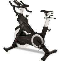
Exterior view of a modern Tocrix exercise bike (no signage or text visible)SRX70
EXPLODED-VIEW & PARTS LIST :
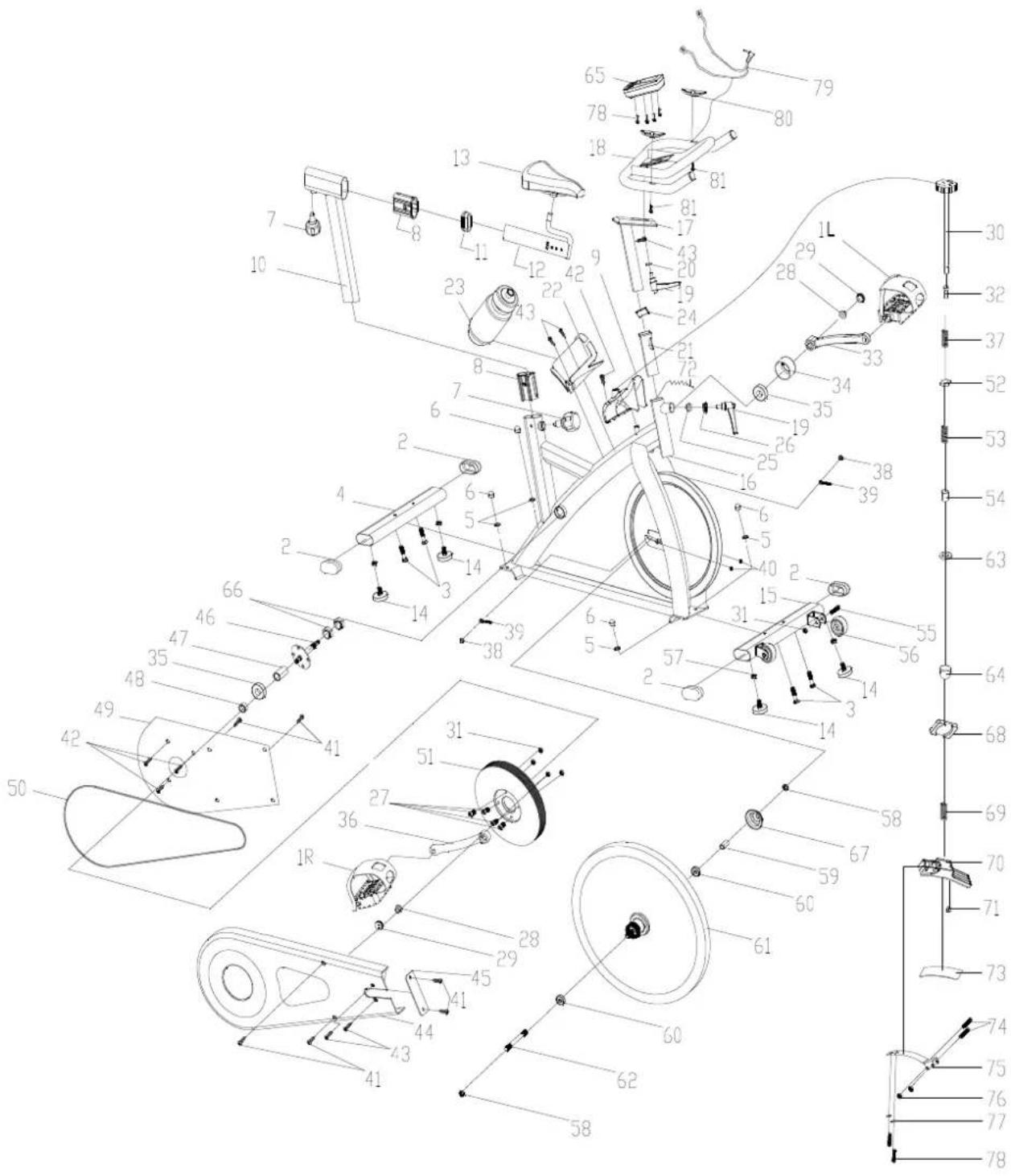
| NO NAME | QUANTITY SPEC | ||
| 1 PEDAL 1 | JD-301 (9/16") | ||
| 2 END CAP1 4 80*40*1.5 | |||
| 3 CARRIAGE BOLT 4 GB/T 12-1988 M8*52 | |||
| 4 | REAR STABILIZER | 1 WELDING | |
| 5 FLAT WASHER 8 GB/T 95-2002 8 | |||
| 6 DOMED NUT 4 | GB/T 802-1988 M8(H=16mm) | ||
| 7 | SPRING ADJUSTMENT KNOB | 2 | 50^82 (M16*1.5) |
| 8 | PLASTIC SLEEVE 1 | 2 70*30*1.5 | |
| 9 | KNOB COVER | 1 | 177X142X187 |
| 10 | VERTICAL SEAT POST | 1 WELDING | |
| 11 | END CAP 2 | 1 70*30*1.5 | |
| 12 | SEAT POST | 1 WELDING | |
| 13 | SEAT | 1 | DD-2681 |
| 14 | STOPPER | 4 | 32^37/(M8X25) |
| 15 | FRONT STABILIZER | 1 WELDING | |
| 16 | MAIN FRAME | 1 WELDING | |
| 17 | HANDLEBAR POST | 1 WELDING | |
| 18 | HANDLE BAR | 1 WELDING | |
| 19 | L SHAPE KNOB 2 | M10*25 | |
| 20 | FLAT WASHER 1 | 1 | 45^ 10.5^5 |
| 21 | PLASTIC SLEEVE 2 | 1 38*38*1.5 | |
| 22 | BOTTLE HOLDER 1 117*85*90 | ||
| 23 BOTTLE 1 XS-003(1#) 500ML | |||
| 24 | END CAP 3 | 1 38*38*1.5 | |
| 25 | FIXING SHAFT | 1 | 22^23 (V) |
| 26 | FIXING NUT | 1 | Q235/32*12 |
| 27 | BOLT | 4 | GB/T 70.2-2000 M8*15 |
| 28 FIXING NUT 1 2 | GB/T 6177.2-2000 M10*1.25 | ||
| 29 | CRANK END CAP | 2 | 23^7.5 |
| 30 | KNOB | 1 | 40^180 ( 10 ) |
| 31 | LOCK NUT | 6 | GB/T 889.1-2000 M8 |
| 32 | BUSHING | 1 | 18^ 10^10 |
| 33 | LEFT CRANK | 1 | 170*27 |
| 34 | CRANK COVER 1 | 56^28 | |
| 35 | BEARING | 2 | 6004ZZ |
| 36 | RIGHT CRANK | 1 | 170*27 |
| 37 | SPRING 1 | 1 | 1.8X40 |
| 38 FIXING NUT 2 2 | GB/T 802-1988 M12X1.25(H=16mm) | ||
| 39 | FIXING BOLT | 2 | M6*57 |
| 40 | NUT | 2 | GB/T 889.1-2000 M6 |
| 41 SCREW 1 8 GB/T 845-1985 ST4.2*19 | |||
| 42 SCREW 2 6 GB/T 15856.1-2002 ST4.2X19 | |||
| 43 SCREW 3 2 GB/845-85 ST4.8X13 | |||
| 44 OUTER CHAIN COVER 1 654*263*49 (507g) | |||
| 45 LITTLE CHAIN COVER 1 108*37*3 (7g) | |||
| 46 AXIS 1 φ20*162 | |||
| 47 | LONG FIXING TUBE | 1 | φ25*φ20.5*41 |
| 48 | SHORT FIXING TUBE | 1 | φ25*φ20.5*9 |
| 49 | INNER CHAIN COVER 1 | 451*260*2 (250g) | |
| 50 | BELT | 1 | 5PK53 |
| 51 | BELT WHEEL | 1 φ200*24 | |
| 52 FIXING NUT 2 | 1 | 16X16X5 (M10) | |
| 53 | SPRING 2 1 φ1.0X55 | ||
| 54 | SHORT FIXING TUBE | 1 | φ14*φ10.2*25.5 |
| 55 | BOLT 2 | GB/T 5780-2000 M8*40 | |
| 56 WHEEL | 2 | φ50*23 | |
| 57 | NUT | 4 | GB/T 41-2000 M8 |
| 58 FIXING NUT 2 | 2 | M12X1.25 H=6 | |
| 59 | FIXING TUBE | 1 | φ16*φ12.1*35 |
| 60 | BEARING 2 | 6001ZZ | |
| 61 | FLYWHEEL | 1 HT250/φ453*72 | |
| 62 | FLYWHEEL SHAFT 1 φ12*160 | ||
| 63 | FLAT WASHER 1 | 1 | GB/T 95-2002 6 |
| 64 | DOMED NUT 1 1 | GB/T 802-1988 M6 | |
| 65 | COMPUTER | 1 | ST-6527(ST-7607) |
| 66 | FIXING NUT | 2 | 27*M20*1 (5mm) |
| 67 | FLYWHEEL COVER | 1 | φ59*35 |
| 68 | SPRING COVER | 1 | 32*23*2 |
| 69 | SPRING 3 | 1 | φ2.2 |
| 70 | PLASTIC FRAME | 1 | 200*47*30 |
| 71 | LITTLE PLASTIC | 1 | 14*9*14 |
| 72 | SENSOR | 1 SR-202 | |
| 73 | WOOLLY BLOCK | 1 | 113*25*6 |
| 74 BOLT 1 | 2 GB/T 5780-2000 M5*30 | ||
| 75 | SPRING BRAKE | 1 | δ1.0 |
| 76 | LOCK NUT 2 | GB/T 889.1-2000 M5 | |
| 77 | SPRING WASHER 1 | 2 | GB/T 859-1987 5 |
| 78 BOLT 2 | 2 GB/T 5780-2000 M5*10 | ||
| 79 | PULSE WIRE | 1 | L=800 |
| 80 | PULSE | 2 | |
| 81 SCREW 5 2 GB/845-85 ST4.2X25 | |||
ASSEMBLY INSTRUCTION:
1.PREPARATION:
A. Before assembling make sure that you will have enough space around the item.
B. Use the present tooling for assembling.
C. Before assembling please check whether all needed parts are available (at the above of this instruction sheet you will find an explosion drawing with all single parts (marked with numbers) which this item consists of.
2.ASEMBLY INSTRUCTION:
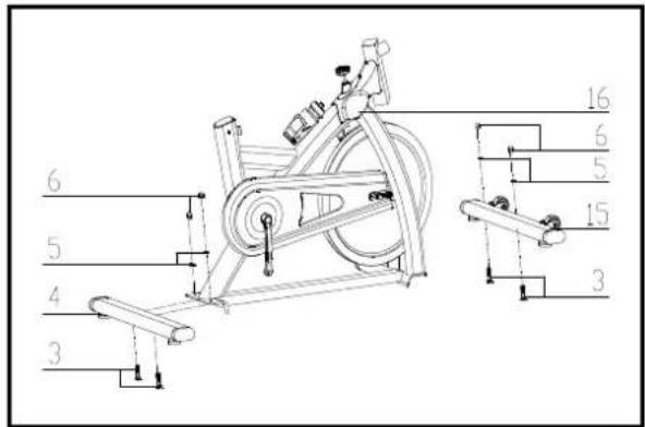
FIG.1

FIG.2
FIG.1:
Attach the Front Stabilizer (pt.15) to the Main Frame (pt.16) using two sets of ∅8 Flat Washers (pt.5), M8 Domed Nut (pt.6) and M8*52 Carriage bolt (3).
Attach the Rear Stabilizer (pt.4) to the Main Frame (pt.16) using two sets of ∅8 Flat Washers (pt.5), M8 Domed Nut (pt.6) and M8*52 Carriage bolt (3).
FIG.2:
Slide the seat post (12) into the vertical Seat post (10) and, at the desired position, align holes and fix in place with the Spring Adjustment Knob (pt.7). Now fix the Seat (13) to the seat post (12) as shown. Insert the vertical Seat Post (10) into the main frame (16) and line up the holes. Secure the saddle in position with the Adjustment Knob (7). The correct height for the seat can be adjusted after the bike is fully assembled.

FIG.3

FIG.4
FIG.3:
Slide the Handlebar Post (pt.17) into the handlebar post housing on the main frame(pt.16). You will have to slacken the knurled section of the L Shape Knob (pt.19) and pull the knob back and then select the desired height. Release the knob and retighten the knurled portion. Then fix the Handlebar (pt.18) with a flat washer 1 (20) and L Shape knob (19)
ATTENTION: YOU SHOULD FIX THE HANDLEBAR TIGHTLY
Fix the Computer (pt.65) onto the Computer Holder of handlebar (pt.18) with bolt(pt.78)
Insert the sensor cable (a) into the bushing located on the backside of the computer (65).
FIG.4:
The Pedals (pt.1 L & pt.1 R) are marked "L" and "R" - Left and Right. Connect them to their appropriate crank arms. The right crank arm is on the right- hand side of the cycle as you sit on it.
Note that the Right pedal should be threaded on clockwise and the Left pedal anticlockwise.
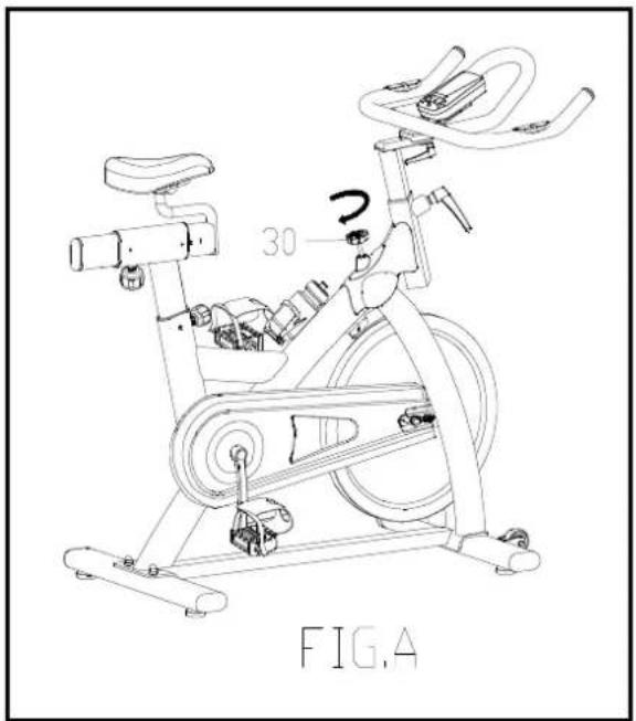
A.) Adjusting the Tension: Increasing or decreasing the tension allows you to add variety to your workout sessions by adjusting the resistance level of the bike.
To increase tension and increase resistance (requiring more strength to pedal), turn the Emergency Brake & Tension Control Knob (#30) to the right.
To decrease tension and increase resistance (requiring less strength to pedla), turn the Emergency Brake & Tension Control Knob (#30) to the left.B.) Using the Emergency Brake Function:
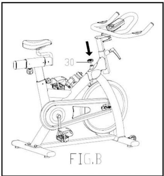
The same knob that allows you to adjust the tension of the bike also doubles as the Emergency Brake. Use this safety feature in any situation where you would need to get off the bike and/or stop the bike's flywheel.
To use the Emergency Brake function in any situation you would need it in, firmly press down on the Emergency Brake & Brake Control Knob (#30).

Garlando
GARLANDO SPA
Via Regione Piemonte, 32 - Zona Industriale D1
15068 - Pozzolo Formigaro (AL) - Italy
www.toorx.it - info@toorx.it


Brand : Toorx
Model : SRX 70
Category : Exercise bike