
BRX-35 - Exercise bike Toorx - Free user manual and instructions
Find the device manual for free BRX-35 Toorx in PDF.


| Product Type | Exercise Bike (Stationary) |
| Brand | Toorx |
| Model | BRX-35 |
| Dimensions (est.) | 100 x 50 x 120 cm |
| Weight (est.) | 30 kg |
| Battery Type | 2 x AAA 1.5V (UM-3) |
| Display Functions | Scan, Time, Speed, Distance, Odometer, Calories, Pulse |
| Heart Rate Monitoring | Hand pulse contact pads |
| Resistance System | Magnetic (tension controller) |
| Max. User Weight (est.) | 120 kg |
| Adjustable Components | Seat (vertical) and handlebar post (horizontal) |
| Auto Shut-Off | After 4 minutes of inactivity |
| Maintenance | Clean with damp cloth; periodically check and tighten bolts |
| Assembly Required | Yes (manual provides step-by-step) |
| Country of Origin | Italy (Garlando SPA) |
| Contact Info | info@toorx.it |
Frequently Asked Questions - BRX-35 Toorx
User questions about BRX-35 Toorx
0 question about this device. Answer the ones you know or ask your own.
Ask a new question about this device
Download the instructions for your Exercise bike in PDF format for free! Find your manual BRX-35 - Toorx and take your electronic device back in hand. On this page are published all the documents necessary for the use of your device. BRX-35 by Toorx.
USER MANUAL BRX-35 Toorx
natural_image
Exterior view of a black exercise bike with adjustable arms and seat (no text or symbols visible)BRX35
i

ASSEMBLY INSTRUCTIONS

Step 1
Assembly the rear and front stabilizer (F&E) with 4 bolts (I-6), 4 nuts (I-8) and 4 washers (I-7).
Step 2
Assemble the left hand pedal (H-L) and the right hand pedal (H-R) to the hand crank.

Step 3
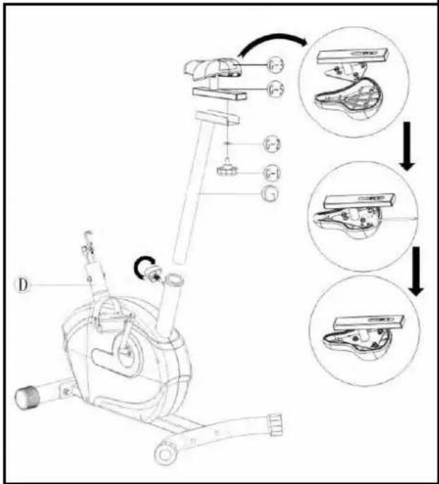
Connect the saddle (G-3) and the slider (G-5) with three bolts and washers.
Attach the slider onto the top of the seat post (G), fix it with one seat knob (G-1) and one flat washer (G-2).
ASSEMBLY INSTRUCTIONS

Step 4
Loosen the four screws (D-4) and four flat washer (D-3) on the support tube of handle bar post.
Insert the handle bar post onto the support tube, connect the tension control cable upper & lower (C-2) & (D-2), connect the sensor cable upper & lower (C-1) & (D-1), fix the handle bar post with four screws and washers.
Step 5
Attach the handlebar (B) to the handlebar post between the steel covers, insert the hand pulse through the hole on hanle bar post, assemble the plastic cover (I-2) over the steel cover, secure the steel cover assembly using one flat washer (I-5), one spring washer (I-4), one bushing (I-3) and one T-knob (I-1).

ASSEMBLY INSTRUCTIONS

Step 6
Connect the sensor cable (C-1) between the computer (A) and the handle bar post, connect the hand pulse cable between the handle bar and computer. Fix the computer with two screws (A-1).
PARTS LIST
| NO. | DESCRIPTION | Q'TY |
| A | Computer | 1PC |
| A-1 | Screw | 2PCS |
| B | Handlebar set | 1SET |
| B-1 | Handlebar foam | 2PCS |
| B-2 | Handle bar end cap | 2PCS |
| B-3 | Hand grip | 2PCS |
| C | Handlebar post | 1SET |
| C-1 | Sensor cable(Upper) | 1PC |
| C-2 | Tension controller(Upper) | 1PCS |
| D | Main frame | 1PC |
| D-1 | Sensor cable(Lower) | 1PC |
| D-2 | Tension controller(Lower) | 1PC |
| D-3 | Semicircular washer | 4PCS |
| D-4 | Hex. Screw | 4PCS |
| D-5 | Seat post knob | 1PC |
| D-6 | Triangle screw | 1PC |
| D-7 | Hex. nut | 1PC |
| D-8 | Have tooth washer | 1PC |
| D-9 | Left thread | 1PC |
| D-10 | Ball retainer | 2PCS |
| D-11 | Bottom bracket | 2PCS |
| D-12 | Grooved belt | 1PC |
| D-13 | Chain cover(R&L) | 2PCS |
| D-14 | Screw | 4PCS |
| D-15 | Screw | 3PCS |
| D-16 | Sleeve | 1PC |
| E | Front stabilizer | 1SET |
| E-1 | Front stabilizer end cap | 2PCS |
| F | Rear stabilizer | 1SET |
| F-1 | Rear stabilizer end cap | 2PCS |
| G | Seat post | 1PC |
| G-1 | Seat knob | 1PC |
| G-2 | Flat washer | 1PC |
| G-3 | Saddle | 1PC |
| G-4 | Cap | 2PCS |
| G-5 | Slider | 1PC |
| G-6 | Fixed screw for slider | 1PC |
| G-7 | Flat washer | 3PCS |
| G-8 | Screw | 3PCS |
| H-R/L | Pedal | 2PCS |
| I-1 | T knob | 1PC |
| I-2 | Plastic cover | 1PC |
| I-3 | Bushing | 1PC |
| I-4 | Spring washer | 1PC |
| I-5 | Flat washer | 1PC |
| I-6 | Carriage screw | 4PCS |
| I-7 | Wave washer | 4PCS |
| I-8 | Nut | 4PCS |
| J-1 | Plastic belt pully | 1PC |
| J-2 | Right thread | 1PC |
| J-3 | Crank | 1PC |
| K | Idler clamping | 1SET |
| K-1 | Idler wheel | 1PC |
| K-2 | Sleeve | 1PC |
| K-3 | Idler spring | 1PC |
| K-4 | Nylon nut | 2PCS |
| K-5 | Hex. screw | 1PC |
| K-6 | Flat washer | 1PC |
| L | Magnetic set | 1SET |
| L-1 | Hex. screw | 2PCS |
| L-2 | Spring washer | 2PCS |
| L-3 | Flat washer | 2PCS |
| L-4 | C-circle | 2PCS |
| L-5 | Wave washer | 1PC |
| L-6 | Mandril | 1PC |
| M | Flywheel | 1PC |
| M-1 | Deep groove ball bearing 6900 | 1PC |
| M-2 | Deep groove ball bearing 6000 | 1PC |
| M-3 | Sleeve | 1PC |
| M-4 | Mandril | 1PC |
| M-5 | Nut | 5PCS |
| M-6 | Star washer | 2PCS |
COMPLETE BIKE ASSEMBLY

EXERCISE COMPUTER
Monitor Display
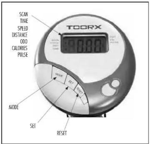
KEY FUNCTION:
MODE: This key lets you to select and lock on to a particular function you want.
FUNCTIONS
| SCAN | Automatically scan through each mode in sequence every 6 seconds. The display loop i SCAN-TIME-DISTANCE-CALORIE-SCAN on the main screen. |
| TIME | Accumulates total working time from 00:00 up to 99:59. |
| SPEED | Displays current training SPEED, the maximum is 99.9km/ml,it always displays. |
| DISTANCE | Accumulates training distance from 0.00 to the maximum 99.99km/ml with each incremer 0.01km/ml. |
| ODO | Press the MODE key until the pointer advance to ODOMETER. The total accumulated distance will be shown. |
| CALORIE | Accumulates calories consumption during training from 0 to the maximum 9999 cal with each increment 1 cal. |
| PULSE | Press the MODE key until the pointer advance to PULSE. User's current heart rate will displayed in beats per minutes. Place the palms of your hands on both of the contact pads (or put ear-clip to ear),and wait for 30 seconds for the most accurate reading. |
NOTE
-
Without any signal been transmitted into the monitor for 4 minutes, the LCD display will shut off automatically, and all function values will be kept. You may press mode or start pedaling to have the monitor power on again.
-
If improper display on monitor, please re-install batteries to have a good result.
-
Battery spec: 1.5v um-3 or AAA (2 pcs).

Garlando
GARLANDO SPA
Via Regione Piemonte, 32 - Zona Industriale D1
15068 - Pozzolo Formigaro (AL) - Italy
www.toorx.it - info@toorx.it


Brand : Toorx
Model : BRX-35
Category : Exercise bike