
SR340 - Security Camera Yale - Free user manual and instructions
Find the device manual for free SR340 Yale in PDF.


| Product Type | Security Camera |
| Brand | Yale |
| Model | SR340 |
| Resolution | 1080p Full HD |
| Field of View | 130° |
| Night Vision | Up to 30 ft (infrared) |
| Connectivity | Wi-Fi 2.4 GHz |
| Dimensions | 6.3 x 3.5 x 3.5 inches |
| Weight | 0.5 lbs |
| Power Source | DC 12V adapter (included) |
| Audio | Two-way audio with built-in microphone and speaker |
| Motion Detection | Yes, with customizable alerts |
| Storage | microSD card (up to 128GB) / Cloud subscription optional |
| App Compatibility | Yale Smart Home app (iOS & Android) |
| Smart Integration | Works with Amazon Alexa, Google Assistant |
| Weather Resistance | Indoor use only |
| Mounting | Wall or ceiling mount (bracket included) |
| Color | White |
| LED Indicator | Status LED (blue/red) |
| Privacy Mode | Yes, physically disable camera via app |
| Certifications | FCC, CE, RoHS |
| Operating Temperature | 32°F to 104°F (0°C to 40°C) |
| Cleaning Instructions | Wipe lens with soft, dry cloth; do not use harsh chemicals |
| Safety Precautions | Use only provided power adapter; keep away from water |
| Spare Parts | Mounting kit and power adapter available from Yale support |
| Repairability | Not user-serviceable; contact support for repairs |
Frequently Asked Questions - SR340 Yale
User questions about SR340 Yale
0 question about this device. Answer the ones you know or ask your own.
Ask a new question about this device
Download the instructions for your Security Camera in PDF format for free! Find your manual SR340 - Yale and take your electronic device back in hand. On this page are published all the documents necessary for the use of your device. SR340 by Yale.
USER MANUAL SR340 Yale
Installation · Programming · Operating
Keep this manual safe for reference and future maintenance
Contents
Thank you for choosing the Yale Smart Home Alarm System. This simple to install system has been designed with the user in mind.
All the components are self contained and no wired connections are needed between the units. There is no need to damage the home decor, lift carpets or run cables.
You can install up to 20 devices (Max. 6 PIR Image / Video Cameras) in this system. As well as extra Door/Window Contacts, PIR Motion Detectors and Smoke Detectors, you can add Key Fob remote controls for added control convenience.
Regular testing and battery changes (when notified by the system) will ensure reliability and peace of mind.
There is no need to wire into the mains supply or seek the services of a qualified electrician. The Smart Hub is powered by an adaptor and all other components are powered by battery (all batteries included).
All accessories are ‘tamper’ protected. Any unauthorised tampering with these items when the system is armed will result in the alarm being triggered.
For more information on this product and Yale Smart Living Range visit www.yale.co.uk/smart-living Consumer Support: info@yale.co.uk
- Location planning 2
- Un-pack all the parts 4
- Initial set-up 5
- Additional accessories 6
- Mounting devices 8
- Using the system 10
- About your Alarm System 12
- Using accessories 13
- Changing the batteries 15
- Troubleshooting 17
- Specifications 19
Recommended Installation Sequence
We recommend you follow the simple install sequence, headings numbered 1-5.

The 2 year guarantee for this Yale Smart Home Alarm Kit is active from the date of purchase (A copy of this guarantee is available on our website).
Please register online within
12 months of purchase at
www.yale.co.uk/registryyourproduct
Information and illustrations are subject to change within this document. Yale reserves the right to alter the specification and product design at anytime without notice. Yale® is a registered trademark. © 2016 ASSA ABLOY. All rights reserved.
Issue No: 1A
1 Location Planning
Work out the best places to locate the devices for maximum protection. Having chosen the locations do not mount at this stage.
Home and Away Mode Planning
The Home Arming mode allows the premises to be part armed so that no one can get inside without warning the occupier, yet the person already inside the house can move freely without triggering the alarm. For example the downstairs of a house can be armed while upstairs can be disarmed allowing the user to go to bed without causing an alarm.
If this feature is to be used, then it should be planned now, before installation.
Decide what areas can be occupied when in Home Arming mode, the sensors for these areas should have its attribute set to "Home Omit" (see page 10 and 12); and the sensors activated on the path to access the Key Pad should be to be set to "Home Access".
Operating Range
All devices must be within 30 metres of the Smart Hub and must not be mounted on or near large metal objects. Avoid obvious sources of electrical interference such as fridges and microwave ovens.
Tamper Switches
When mounting devices ensure that any tamper switches close fully. On uneven surfaces it may be necessary to place packing behind the switch for reliable operation.
Extend the System
Extend the system in the future to increase your security or as your needs change.
For example, add extra PIR Motion Detectors and extra Door/Window Contacts.
You can add up to 20 devices, of which a maximum of 6 of these could be PIR Image or PIR Video Cameras.
Choosing Location
To minimise interference, avoid locating devices close to metal framework, glass, electrical appliances (especially wireless devices) and electric cables.
Please note that the presence of high density material (metal, glass etc) in the transmission path will significantly reduce the wireless transmission range.
Key Pad
When used as a secondary Key Pad, it is ideal for use in bedrooms or at the top of a stairwell so the ground floor can be armed when going to bed for the night, or, at a side or back door for alternative entry point.
- Mount at chest height for ease of use
- Designed for indoor use only
• Key Pad should be accessible from a protected entry/exit point - Ensure that the Key Pad is not visible from the outside of the premises.

natural_image
Diagram of a room interior with door, window, and wall-mounted sensors (no text or symbols)Panic Button
The Panic Button provides extra protection for you and your family. When help is needed the Panic Button can activate your alarm immediately - even when the system is disarmed.
- Mount at chest height for ease of use
- Mount on flat wall surface
- Designed for indoor use only
• Out of reach of children - Hidden from view while easily accessible.
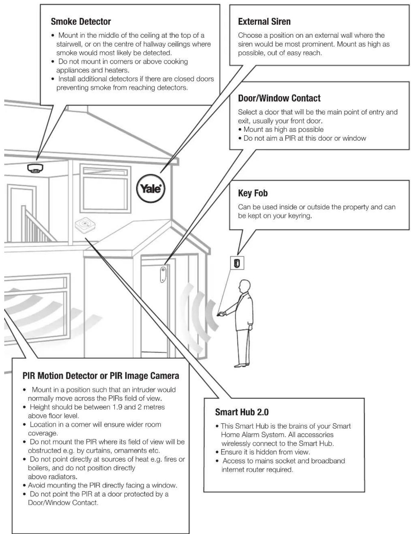
flowchart
graph TD
    A["Smoke Detector"] --> B["Mount in the middle of the ceiling at the top of a stairwell, or on the centre of hallway ceilings where smoke would most likely be detected.<br>Do not mount in corners or above cooking appliances and heaters.<br>Install additional detectors if there are closed doors preventing smoke from reaching detectors."]
    C["External Siren"] --> D["Choose a position on an external wall where the siren would be most prominent. Mount as high as possible, out of easy reach."]
    E["Door/Window Contact"] --> F["Select a door that will be the main point of entry and exit, usually your front door.<br>Mount as high as possible<br>Do not aim a PIR at this door or window"]
    G["Key Fob"] --> H["Can be used inside or outside the property and can be kept on your keyring."]
    I["PIR Motion Detector or PIR Image Camera"] --> J["Mount in a position such that an intruder would normally move across the PIRs field of view.<br>Height should be between 1.9 and 2 metres above floor level.<br>Location in a corner will ensure wider room coverage.<br>Do not mount the PIR where its field of view will be obstructed e.g. by curtains, ornaments etc.<br>Do not point directly at sources of heat e.g. fires or boilers, and do not position directly above radiators.<br>Avoid mounting the PIR directly facing a window.<br>Do not point the PIR at a door protected by a Door/Window Contact."]
    K["Smart Hub 2.0"] --> L["This Smart Hub is the brains of your Smart Home Alarm System. All accessories wirelessly connect to the Smart Hub.<br>Ensure it is hidden from view.<br>Access to mains socket and broadband internet router required."]
2 Unpack all the parts
Smart Hub 2.0
- Unpack the kit content on a table. Remove the mounting plate (if fitted) from the Smart Hub by sliding plate downwards. A power adaptor is supplied that plugs into the main wall socket and Smart Hub. Plug in the power adaptor and connect the Smart Hub to your internet router using the cable provided.

- In addition to the adapter, there is a rechargeable battery inside the Smart Hub that serves as a backup in case of a power failure. A fully charged battery can provide backup standby power for a period of approximately 5 hours. It takes approximately 72 hours to fully charge the battery. The battery must always be turned on.
- Remove the rubber battery switch cover and locate the battery switch. Switch ON the internal battery and replace the rubber cover.
Smart Hub LED's
Top LED Green = Linked to the Server/Internet
Top LED not lit = No link to the Server/Internet

natural_image
Simple line drawing of a square electronic component with concentric circles and a central hole (no text or symbols)Middle LED Yellow = System Fault Further details can be found in the App
Middle LED not lit = System OK
Bottom LED solid red = System Armed Bottom LED flashing red = System part Armed Bottom LED not lit up = System Disarmed
Key Pad EF-KP
- Pull out the plastic battery saver tab at the back of the Key Pad. This will activate the batteries.

- All accessories in the kit box are already pre-learned to the system.
PIR Motion Detector EF-PIR
- Pull out the plastic pull tab on the back of the PIR. This will activate the batteries.
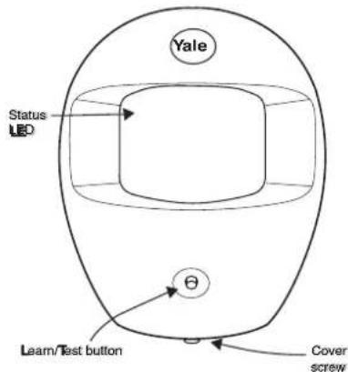
- All accessories in the kit box are already pre-learned to the system.
Not Included in the Starter Kit Door/Window Contact EF-DC (SR-320, 330 & 340 Kits)
- Pull out the battery saver tab on the side to activate the battery. LED

- All accessories in the kit box are already pre-learned to the system.
3
Additional Accessories
External Siren EF-BX (SR-320, 330 & 340 kits)

WARNING
The Siren is very loud, be prepared! Take care not to activate the Siren tamper switch unnecessarily.
- Remove the cover by unscrewing the single screw located on the lid. Power switch to ON position.

Smart Home Alarm Accessories:
- Insert AA/AAA batteries (supplied). Power Switch does not require any battery.
PIR Image Camera SR-PC (SR-330 & 340 Kits & Sold Separately) PIR Video Camera SR-PVC (Sold Separately) 1. Open back of PIR Video
- Pull out the plastic tab on the back of the PIR Image Camera activate batteries.

-
Learn: Hold for 10 seconds Test: Hold for 1 second
-
Open back of PIR Video Camera to insert batteries.

- Learn: Hold for 10 seconds Test: Hold for 1 second
Power Switch SR-PS (SR-340 Kits & Sold Separately)
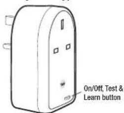
- Learn: Hold for 10 seconds Power On/Off: Press & release Test: Press & release
Keyfob EF-KF (Sold Separately)
- Open the battery compartment using a coin by turning cover in the direction of the big arrow so the small arrow is next to round dot.
- Insert CR2032 battery (supplied) and replace cover.

Smoke Detector EF-SD (Sold Separately)
- Remove the cover and insert three AA batteries (supplied)
- The Smoke Detector will now enter into self-calibration mode for 10 minutes. It will resume normal operation after this period.


natural_image
Diagram of a mechanical component with a rotating arrow indicating rotation (no text or symbols)Panic Button EF-PB (Sold Separately)
Remove the cover by loosening the fixing screw and insert the CR2032 battery (supplied) as shown (1). Please ensure you observe battery polarity and insert the battery under the two tabs and click into place (see image on page 16)

PET PIR Detector EF-PETPIR (Sold Separately)

flowchart
graph TD
    A[" nucleus "] --> B[" mitochondria"]
    B --> C[" Golgi "]
    C --> D[" Sensor "]
    style A fill:#f9f,stroke:#333
    style B fill:#ccf,stroke:#333
    style C fill:#cfc,stroke:#333
    style D fill:#fcc,stroke:#333
This pet friendly accessory will activate the alarm when large motion is detected. Ideal for homes with one small pet (less than 25kg). Please note when used with large pets there is an increased possibility of false alarms. In these scenarios use a Door/Window Contact to protect the area instead.
Initial set-up
Please ensure all devices are powered and operational at this point.
Download Yale App (Smartphone)
Search term in App Store: Yale Home System Compatibility: iOS 9, Android 4.2+ Internet Connection: Required on Smartphone

Available on the App Store

ANDROID APP ON Google play

First time registration
Start The Yale Home System App on your phone. *Due to continuous improvement, please note that the graphic may differ from shown.
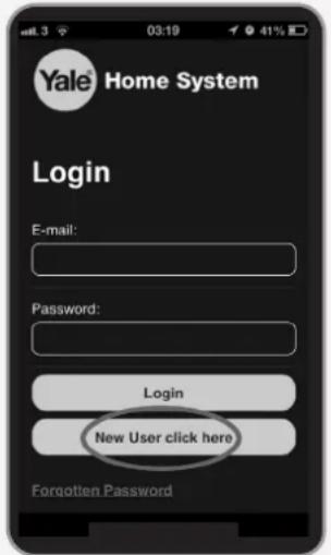
Select
New user click here
Further down on this start page you can set Language.


Enter your details
Panel Serial Number can be found on the Smart Hub sticker.

If you encounter errors, it is due to the Smart Hub not communicating with our server. Please see troubleshooting "Warning LED" (see page 18). You will be asked to set-up a password when registration is successful. Please use your email and this new password to login via the front page.
Recording your set-up information
| E-mail used to set up system: | |
| Smart Security Hub 2.0 serial number | |
| Phone number used for notifications: | |
| Keypad PIN Code for Disarm/Arm (default 1234): | |
| Keypad code for keypad setting (default 0000): |
Make sure you keep this manual in a safe and convenient place for future reference.
Adding Accessories (if you purchased extra accessories)
All accessories in the kit are linked to the Smart Hub. If you purchased extra accessories (or for some reason the accessories are deleted), please do the following:
1

-
Press and hold the learn button on your Smart Hub. you will hear a beep, after 6 seconds you will hear a slightly longer beep.
-
Your Smart Hub is now in learn mode.
2
One by one, press the learn button on the accessory according to below. The Smart Hub will beep (single or multiple dependent on device) when a new device is registered, and after a couple of seconds you will see it in your Device List on your App.

For the following accessories, please hold the Learn button for 10 seconds before releasing to enter Learn mode.
Learn/Test button Hold for 10 seconds
If the accessory doesn't learn. Remove the batteries for 5 seconds then replace and try relearning within 3 minutes.

SR-PCSR-PVCSR-PS

natural_image
Line drawing of a door with handle and control knob (no text or symbols)Learn/Test button Hold for 10 seconds
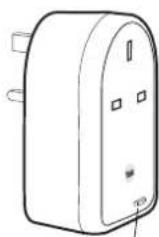
Learn/Test button
Hold for 10 seconds
3
Exit Learn Mode:
- Press and hold the Smart Hub 2.0. Learn button for at least 6 seconds.
After the 6 seconds you will hear a slightly longer beep. - Your Smart Hub is now out of Learn mode.
4 Mounting Devices
Smart Hub 2.0 Mounting
The Smart Hub can be free standing, either vertically or horizontally on a flat surface with access to mains socket and broadband internet router.
It is also suitable for wall mounting. Using the two holes on the mounting back plate, mark the position of the holes. Drill two holes and fix with the screws and plugs provided. Hook the Smart Hub onto the plate.
Check Accessories Range
Find a location where the device is to be mounted, see section "Location Planning" for suggestions.
Before proceeding to mount the devices physically, check that the Smart Hub will receive the system radio transmissions by doing a simple radio range test.
Login to your Yale Home System App. Select "Controller", "Device List" then select "Walk Test".

Hold the devices in the desired location and press the Test/Learn button (see below) on the accessories.
- KEY PAD: Press button 8 + 9 together for 1 second.
- ALL OTHER DEVICES (Except for the SR-PC SR-PVC & SR-PS): Hold the device in the desired location and press the test button for 1 second, the Smart Hub should respond with a chime.
For the SR-PC, SR-PVC & SR-PS hold the test button for 3 seconds.
If the sensor signal reached the Smart Hub, it will show up on the last screen (see above).
The radio signal strength is shown by a number under the device name. This number ranges from 1 to 9 (strongest). Where possible please ensure devices show 3 or above for optimal performance.
When you are happy that all your devices can communicate with the Smart Hub, please proceed to mounting the accessories
Mounting the PIR & PIR Image/Video Camera
-
Open the PIR by loosening the bottom screw. Knock out the relevant holes on the base where the plastic is thinner. The center 2 knockout holes are for flat wall mounting while the 4 side holes are for corner mounting.
-
Drill holes into the wall using the knockout holes on the base as a template.
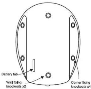
-
Fit wall plugs and secure the PIR base with the screws provided.
-
Fit the PIR back together and tighten bottom screw, the PIR installation is complete.
Mounting the Key Pad

-
Knock out the fixing holes. Drill holes into the wall using the fixing holes as a template.
-
Fit wall plugs into the wall and fix back cover with the screws provided. Fix front of the Key Pad onto the back plate.
Mounting the Door/Window Contact
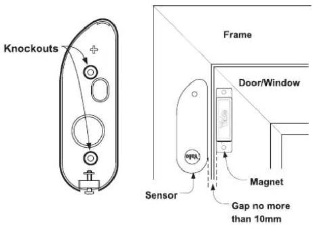
Note: The Door/Window Contact and magnet can be changed round as long as there is no more than a 10mm gap.
- Find a location on the door/window where you would like the device to be mounted. The sensor should be on the frame while the magnet should be on the door/window. Once mounted make sure the tamper switch spring is fully depressed.
The gap between the magnet and sensor should be no more than 10mm when closed (maybe shorter depending upon the actual environment). Simply test to see whether the magnet is in range of the sensor: hold the magnet and sensor in place and then pull them apart. If the sensor LED lights up it implies the two items are within range.
Mounting using adhesive pads
Clean the mounting surface with a suitable degreaser agent. Please note that some surfaces may be unsuitable for this mounting method. Please use screw mounting in these cases.
Mounting using screws & wall plugs
Loosen the bottom screw and open the door/window contact. Knock out the holes on the base as shown. Drill holes into the mounting surface using the holes in the knockouts on the base as a template. Fit wall plugs (if required) and secure with the screws provided.
Mounting the External Siren
Ensure the tamper spring is fully compressed when the siren is mounted. If there is a gap, pack with a suitable spacing material.
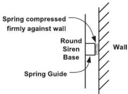
- Using the large screws and wall plugs provided, screw the Siren onto the wall through the 4 mounting holes on the Siren base.
- Fix the Siren cover with the securing screw.
Mounting the Panic Button
- Break through the knockouts (where the plastic is thinner).
- Using the holes as a template, drill holes in the surface and insert wall plugs if fixing into plaster or brick. Screw the rear case to the wall. Replace the cover and tighten the screw.
Mounting the Smoke Detector
- The base has two mounting slots. Using the slots as a template, drill holes and insert the wall plugs if fixing to plaster. Screw the rear case to the ceiling using the screws provided.
- Replace the main unit onto the bracket.
Display extreme caution when using ladders or steps, please follow manufacturer's instructions.
Be careful when using hand and power tools and follow the manufacturer's guidelines when using them. Take care that the correct tools are used. Wear goggles or protective clothing where required. The Siren is extremely loud, please ensure to retreat to a safe distance before testing.
5 Using the System

Note! The PIR Motion Detector and PIR Image Camera have a built in battery save mode. After detecting motion, they will wait for one minute without motion before sending any signals to the Smart Hub. This saves battery power.
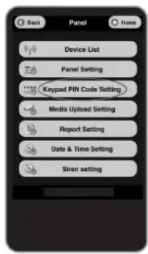
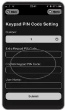
Changing your Key Pad PIN
The default Key Pad PIN is 1234. You can set up to 6 sets of 4 digit PIN numbers by:

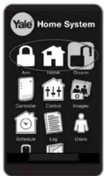
Arming and Disarming your Alarm
Using the Yale Home System App
Setting up Home Arm Mode
The Home Arm Mode allows the home to be partially armed so that no one can get inside without first disarming the system. However, the person inside the house can move freely around without triggering the alarm. Home mode is usually used to protect the ground floor when you are upstairs in bed.
To enable Home Arm, you need to choose the sensors to be ignored whilst in this mode. It would typically be the bedroom PIR etc if you want to arm your system during the night. These sensors should be set to Home Omit in order to be ignored during Home Arm Mode. If you wish to trigger an alarm count down with a sensor during Home Arm Mode, allowing you time to disarm the alarm when coming home, please select the mode: Home Access.
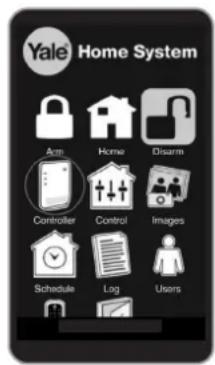


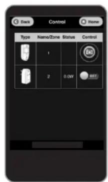
Manually requesting PIR Images
During an alarm, the PIR Image/Video Camera will send images/video to your phone. You can also manually request these images/video. Still images take an average of 15 seconds before showing on your phone, and video takes approximately 1 minute. Click on "image" to view images/videos.
Note: Up to 50 images/videos can be kept in the Yale Server (the oldest images/videos are automatically deleted to make space). Users are advised to delete unwanted images/videos.

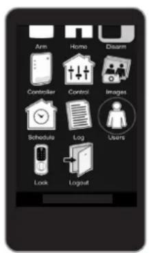
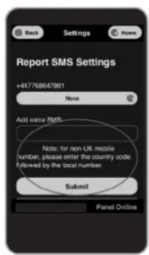
Adding alert email/SMS
You can add/delete email and SMS phone numbers for alert during alarm condition. Only burglar events will be reported via SMS, while you can choose to have ALL events (or Burglar only) reported via email.
Hint: our report email will use the email address of: report@yalehomesystem.co.uk Save this email address as your VIP (Apple iOS) or Priority (Android) email and assign a special ringtone to it.
Using the Key Fob (EF-KF) or Key Pad (EF-KP)
Away Arm & Home Arm
Press the Away Arm/Home Arm key on the Key Fob or Key Pad.
Disarm
Press the disarm key on the keyfob or press the disarm key followed by a PIN on the Key Pad.
6
About your Alarm System (Default Settings)
All accessories (except SR-PC and SR-PVC) are pre-set to "entry" mode.
When the system is first armed, users will have 30 seconds to exit the building. If the system is already armed, triggering any sensors will cause an entry countdown to begin.
SR-PC/SR-PVC's default setting is "Burglar only", i.e. immediate triggering during full arm and sleep during Home Arm. This is done to conserve battery life.
To change the behavior mode on accessories, please see APP - "Controller" -> "Device List" -> choose each device to change.
- Burglar - Instant Alarm upon activation in both Away and Home Mode
- Home Omit - No activation under Home Mode, but will in Away Mode.
- Home Access - Give 30 sec. delay when activated under Home Mode, Instant Alarm upon activation in Away Mode
- Entry Zone - Upon activation gives a 30 sec. delay in both Away and Home Mode.
To change the exit and entry timer, please enable via App -> "Controller" -> "Panel Setting"
When the alarm is triggered, the system will send an email, push notification and SMS to alert the owner.
The network traffic condition will determine how quickly the user is alerted. There may be a noticeable delay should the third party email/SMS gateway become congested.
It is not possible to arm the system with “open” Door/Window Contact (i.e. windows open).
You will be prompted on the App when trying to arm with your door/window open.
Jamming and interference detection disabled as default.
If jamming and interference is of concern, please enable via "Controller" -> "Panel Setting"
Supervision is set to disabled as default (recommended).
Enable or disable supervision detection on the Smart Hub. PIR, Door/Window Contact, or Siren can be monitored for outage and malfunctions using this feature. With the exception of the PIR Image Camera, PIR Video Camera and Smoke Detector (which are always on), the other three accessories need to have supervision enabled on board to facilitate this feature.
Note: Do not enable this unless advised by a professional installer.
Supervision can be enabled via "Controller" -> "Panel Setting".
External Siren Comfort LED is set to disabled as default (recommended).
The Comfort LED function starts a flashing light on your external Siren when enabled. This function will significantly reduce the battery life of your Siren.
You can enable the Comfort LED via "Devices" -> "Siren Properties" (arrow on the right).
7 Using Accessories
To provide additional flexibility and protection you can add extra Key Fobs, Key Pads, Panic Buttons and Smoke Detectors. These are available separately from your local stockist.
Adding Accessories to your System (See page 7)
Using your Key Fob
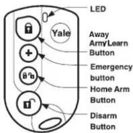
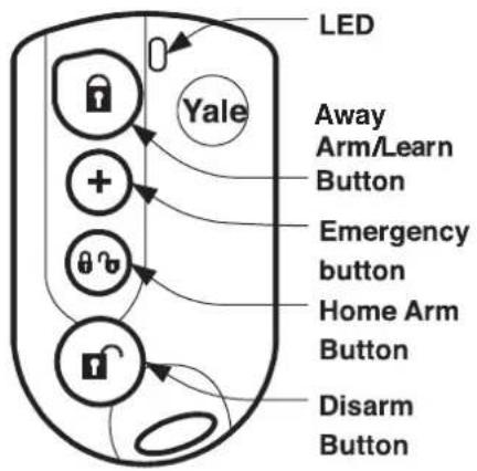
- The Key Fob can be used to Away Arm, Home Arm, and Disarm the system using the buttons as shown.
- An emergency alarm can be activated by pressing the emergency button for 3 seconds until LED stops flashing.
- An emergency alarm can only be stopped by using the Key Pad.
Key Pad
Key Pad Initialisation
If you purchase a Key Pad as an extra Key Pad, you will need to initialise it prior to use with the Smart Hub.
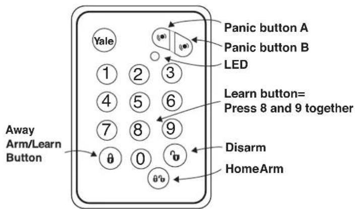
1 Press 'Panic button A' followed by factory default Key Pad code '0000'.
2 The LED will now flash slowly indicating it is in test (programming) mode.
3 Press 'Panic button A' followed by the '7' key to set the Key Pad into Smart Hub system mode (also known as slave mode).
4 Quit test mode by pressing the disarm key twice. The Key Pad code and Mode setting has been completed.
7
Using Accessories (cont.)
Reset Key Pad code
If the Key Pad code is accidentally forgotten, the Key Pad can be reset to factory default (0000) using the following steps:
- Unscrew the two Key Pad case screws and remove Key Pad back cover (please disable tamper first). Locate and remove the battery. See battery change section (16-17)
- Press the number '4' key at the same time as reinserting the battery.
- Screw the Key Pad case together and re-learn the Key Pad into the system using the steps described above in this section.
Using your Key Pad
- The Key Pad can be used to Away Arm and Home Arm the system using the buttons as shown.
- The system is disarmed by pressing the disarm button followed by your PIN code.
- An emergency alarm can be activated by pressing the panic A and B buttons simultaneously. Deactivate panic event by pressing the disarm button followed by your PIN code.
- If there is a system fault, you will need to press the Arm/Home Arm button for a second time to "force arm" the system.
Using your Smoke Detector
Smoke Detection
When smoke is detected the device will activate for a minimum of 10 seconds with a two tone alarm and flashing LED. The Detector will send a radio signal to the Smart Hub. You will then be notified via a push notification, SMS and email.
- Pressing the test button when in an alarm condition will silence the alarm for 10 minutes. It will automatically resume smoke detection again after this period.
Testing
- Smoke Detector testing should be done on a regular monthly basis. Pressing the test button will make the LED flash, the audible sounder chime and will send a radio test signal to the Smart Hub when the button is released. If nothing happens after pressing the test button, it indicates the batteries will need changing.
Recalibration
- The Smoke Detector might need recalibrating after time to ensure it is working at its optimum. This is done by pressing and holding the test button until the LED flashes and beeps after 10 seconds. The Detector will then start its self calibration routine.
Using your Panic Button
Activate an Alarm
- Press and hold the red button for at least 3 seconds. The LED will light momentarily and the alarm will be activated.
Silence an Alarm
- Press and hold down the red button for 10 seconds. The LED will light momentarily for a second time and the alarm will be silenced.
- Please note that silencing the alarm with the Panic Button does not reset the system. If the alarm is armed prior to activation, the system will re-arm after being silenced with the Panic Button.
- The system will require a reset at the Smart Hub after being silenced with the Panic Button.
8
Changing the Batteries
Always use correct type of batteries as replacements because any other battery can cause problems with the operation of the system. Ensure the correct steps are taken when changing batteries in tamper protected devices.
Low Battery Indication
The App will display the low battery message under the actual device.

When a device first shows the low battery signal it has enough battery capacity to operate for a further month before complete exhaustion.
Door/Window Contact Battery Change
When the battery is low the LED will light up when the door/window is opened. The battery is changed as follows:
- Ensure the system is disarmed.
- Loosen the case screw and remove the Door/Window Contact from the base to reveal battery.
- Using a screwdriver gently lever out the old battery.
- Insert new CR2032 coin cell battery with the + side uppermost. See picture on page 16.
-
Press battery into holder firmly with finger and thumb until a click is heard.
-
Refit sensor on base and tighten bottom case screw. Switch tamper protection back on.
- Door/Window Contact case tamper conditions are also indicated by a lit LED, check the tamper before changing the battery.
PIR Motion Detector & Image / Video Camera Battery Change
When the battery is low the LED will flash when any motion is detected. The batteries are changed as follows:
- Ensure the system is disarmed.
- Loosen the case screw and remove PIR from base to reveal the batteries.
-
Insert new batteries observing correct polarity. (Note: PIR Motion Detector takes 3x AAA alkaline batteries, PIR Image Camera takes 2x AA alkaline batteries and PIR Video Camera takes 3 x AA Lithium batteries. The PIR LED will flash for 30 seconds while initialising.
-
Refit PIR on base and tighten bottom case screw.
- Ensure tamper spring is fully depressed when re-fitting the PIR to the back case. If this has not been done correctly this will be indicated by a flashing LED on the PIR.
External Siren Battery Change
When the batteries start getting low the Siren will produce a series of audible pips and flashes during arming and disarming.
- Ensure the system is disarmed. Select "Controller", Device List", click Siren's Properties (icon on the right) and set Siren Bypass to the OFF position.
- Remove the Siren lid and switch the Siren power switch to OFF.
- Unscrew the four screws on the battery compartment lid and remove the cover.
- Remove the four batteries, wait for 30 seconds, and replace them with four fresh alkaline "D" batteries.
- Switch on Siren power and check that the Siren beeps and flashes.
Warning: After the batteries have been inserted, the tamper will become active after three hours. Please replace the cover back onto the Siren quickly.
- Siren case tamper conditions are also signalled by a series of beeps when the system is armed but not when the system is disarmed (low battery warning produces a series of audible pips when armed and disarmed), take care not to confuse the two different conditions.
8
Changing the Batteries (cont.)
Key Fob Battery Change
When the battery is low the LED will glow dimly when any key is pressed. The battery is changed as follows:
- Using a coin turn the battery cover anticlockwise to the unlocked position and remove cover and battery.
- Insert new CR2032 coin cell battery with the + side uppermost.
- Replace battery cover.
Press any key and check that the LED lights. If the LED lights the new battery installation is successful.
Key Pad Battery Change
When the battery is low the LED will flash when any key is pressed. The battery is changed as follows:
- Ensure the system is disarmed.
- Unscrew the two Key Pad case screws and remove Key Pad back to reveal battery.
- Using a screwdriver gently lever out the old battery.
- Insert new CR2032 coin cell battery with the + side uppermost. (See picture below).
- Press battery into holder firmly with finger and thumb until a click is heard (see picture below).
- Press a number key and check that the LED lights. If the LED lights the new battery installation is successful, screw the Key Pad case back on and the battery change is complete.
Panic Button Battery Change
When the battery is low the LED will glow dimly when the button is pressed. The battery is changed as follows:
- Loosen the bottom case screw and take button cover off base.
- Insert the new CR2032 coin cell battery with the + side uppermost (see picture below)
- Replace button cover.
Press the button and check that the LED lights. If the LED lights the new battery installation is successful.
Smoke Detector Battery Change
When the battery is low the LED will flash accompanied by a low volume beep once every 30 seconds.
- Rotate Smoke Detector anti-clockwise to detach from base bayonet fixing.
- Insert new AA alkaline batteries, taking care to observe polarity and wait 15-20 minutes for the Smoke Detector to recalibrate itself, indicted by a rapidly flashing LED.
- Replace Smoke Detector on base and rotate clockwise to lock.
- Press the test button and check that the LED lights and the sounder chimes to confirm the new battery installation is successful.
Battery Removal and Insertion. Door/Window Contact Key Pad and Panic Button

IMPORTANT
Insert the battery under the two tabs and click into place.

External Siren
Siren produces a 3 second alarm when disarmed
- There has been a previous alarm and there might be an intruder still in the premises.
Siren produces a series of audible pips when armed or disarmed
- If the Siren produces a series of pips when arming and disarming this indicates low batteries.
- If the Siren produces a series of pips only when arming this indicates a tamper fault. Check that the Siren cover is firmly secured and the tamper spring on the back of the Siren is fully depressed when in contact with the wall. If not use suitable packing material to fill the gap (refer to page 9 for diagram).
Siren produces an interrupted tone when sounding an alarm
- The Siren has low batteries. Change batteries with new alkaline replacements (see page 15).
External Siren
Siren does not respond to Arming or Disarming
- Siren batteries are completely exhausted. See instructions for changing batteries on page 15.
- Siren not learnt-in. If Siren produces a tamper alarm when the cover is removed and Siren is OK, learn-in the Siren (see page 7).
- Siren is not in range of the Smart Hub.
If you experience a problem with adding the External Siren to you Alarm system
- Ensure the dip switch positions are as shown in the diagram. If the switches are in the wrong position, please change accordingly
- After changing the dip switch, turn off the power for 30 seconds, then turn the power on again for the changes to take effect.

natural_image
Isometric diagram of a 3D block structure with numbered faces (1-4), no text or symbols present.NORMAL
Door/Window Contact
Door/Window Contact LED lights up
- Batteries are low or the tamper switch has been disturbed. Check that the tamper switch spring is making contact with the mounting surface. If the tamper switch is OK, please change the battery (see page 15).
Door/Window Contact does not respond to opening when jumper is in the test position
- Batteries are completely exhausted. Change battery (see page 15).
- The magnet is too far away from the Door/Window Contact. Check that the gap between the Door/Window Contact and magnet is not greater than 10mm.
PIR Motion Detector
PIR does not respond to motion
- Previous motion has triggered the PIR sleep timer and is preventing subsequent motion detection. Arm the system and vacate protected area for at least 90 seconds before testing. By pressing the learn/test button the PIR LED will light up and detect motion for the first minute.
PIR Motion Detector is slow to respond
- This is normal, the PIR Motion Detector has sophisticated false alarm filtering that will filter out random fluctuations and responds to genuine motion across field of view, it is less sensitive walking directly towards it.
PIR Motion Detector gives false alarms
- Check pets have no access to the protected area.
- Check that the PIR Motion Detector is not pointed at sources of heat or moving objects, e.g. fluttering curtains.
- Check that the PIR Motion Detector is not mounted above convector heaters or pointing directly at windows.
PIR Motion Detector LED flashes
- Batteries are low or the tamper switch is disturbed. Check that the tamper switch spring is making contact with base. If the tamper switch is OK, change batteries with new AA alkaline replacements (see page 15).
PIR Motion Detector does not respond to movement
- Batteries are completely exhausted. Change the batteries with new AA alkaline replacements (see page 15)
PIR Image/Video Camera
PIR Image/Video Camera LED flashes every 20 minutes
- PIR Image/Video Camera is not in range of the Smart Hub.
* If a PIR Image/ Video Camera is not learnt into the system or within range of the Smart Hub, battery life will be greatly affected while it searches for a connection.
Smart Hub LED 2 (Warning LED)
Top LED Green = Linked to the Server/Internet
Top LED not lit up = No link to the Server/Internet
Middle LED Yellow = System has Fault. Further detail will be found in the Yale App
Middle LED not lit = 0K
Bottom LED solid red = System Armed
Bottom LED flashing red = System Part Armed
Bottom LED not lit up = System Disarmed
Consumer Support Helpline
Should you have any questions or experience a problem with your Smart Home Alarm Kit, please contact our Consumer Support Helpline.
Tel: 01902 364606
Monday - Friday 8.30am - 5.30pm
Email: info@yale.co.uk
10
Specifications
All devices
Environmental Conditions
-10°C to 40°C, relative humidity 70% non-condensing for all units except the external Siren. Siren: -20°C to 50°C, relative humidity 95% non-condensing
Radio operational range
30m in a typical domestic installation, range can vary depending on building construction, device positions and RF environment
Housings ABS/polycarbonate
Smart Hub 2.0
Siren Output 100dBA sound pressure @ 1m minimum
Zones 20 radio devices
Radio system 868MHz FM, 2.4GHz
Power supply Plug top adaptor type, input 230VAC 50Hz, output 9VDC, 1A, tested to EN 60 950
Rechargeable battery Ni-MH, 4.8V 600mAh, charge time 72hrs, standby time 10hrs
External Siren
Siren Output 104dBA sound pressure @ 1m minimum
Radio 868MHz FM
Power supply 6V, 4 x D alkaline batteries.
PIR Motion Detector
Alarm processing Microprocessor controlled dual edge sequential pulse count with pulse length discrimination
Radio 868MHz FM
Power supply 4.5V, 3 x AAA alkaline batteries.
Motion Detector range 12 metres 110°
Door/Window Contact
Radio 868MHz FM
Power supply 3V, CR2032 lithium coin cell battery
PIR Image Camera
Alarm processing Microprocessor controlled dual edge sequential pulse count with pulse length discrimination
Radio 2.4GHz
Power supply 2 x AA 1.5V alkaline batteries
Movement detection range 110°
PIR Video Camera
Alarm processing Microprocessor controlled dual edge sequential pulse count with pulse length discrimination
Radio 2.4GHz
Power supply 3 x AA Lithium batteries.
Motion Detector range 12 metres 110°
Smoke Detector
Radio 868MHz FM
Power supply 4.5V, 3 x AA alkaline batteties
Tested to EN54
Key Fob
Radio 868MHz FM
Power supply 3V, CR2032 lithium coin cell battery.
Key Pad
Radio 868MHz FM
Power supply 3V, CR2032 lithium coin cell battery.
Panic Button
Radio 868MHz FM
Power supply 3V, CR2032 lithium coin cell battery.
Special notes on compatibility:
This alarm system is NOT compatible with HSA6000 series and HSA3000 series accessories. Please note the prefix "EF" or "SR" on the front of the part number to indicate compatibility.
The phone feature and remote notifications require our central server. Yale does not guarantee limitless and future availability of our free server. We would contact individual users via e-mail should this situation change.
In the unlikely event of server disconnection, the alarm system will continue to function (arm/disarm) using the supplied Key Pad accessory.
ASSA ABLOY Ltd.
School Street, Willenhall
West Midlands
England, WV13 3PW
EC Declaration of Conformity
We: ASSA ABLOY Ltd
School Street, Willenhall
West Midlands
England, WV13 3PW
Declare under our sole responsibility that the following product(s):
Yale Model:
| SR-PIR | EF-PIR |
| SR-PETPIR | EF-PETPIR |
| SR-DC | EF-DC |
| SR-KF | EF-KF |
| SR-KP | FE-KP |
| SR-PB | EF-PB |
| SR-SD | EF-SD |
| SR-BX | EF-BX |
| SR-PC | EF-BXINT |
| SR-PVC | EF-PANEL |
| SR-PS | EF-IPBOX |
| SR-RS | EF-INTBOX |
| SR-SR | EF-Easy Fit Alarm Kits |
SR-EIR
SR-SR
SR-WS
SR-CO
SR-HUB
SR-HUL
SR-HSL
SR-MZ8
SR-Smart Home Alarm kits
SR-Standard Alarm kits
SR-Smartphone Alarm kits
Is (are) in conformity with the following relevant harmonized standards:
EN 300-220-1 / v 2.4.1 (2012)
EN 300-220-2 / v 2.4.1 (2012)
EN 301-489-1 / v 1.9.2 (2012)
EN 301-489-3 / v 1.6.1 (2012)
EN 60950-1 / 2006 + A11: 2009 + A1: 2010 + A12: 2011 + A2: 2013
Following the provisions of Council Directive 1999/5/EC on radio equipment and telecommunications terminal equipment and the mutual recognition of their conformity.
Name: Nigel Fisher
Position: Director
Signature:

On behalf of ASSA ABLOY Ltd.
NoPb
C€

Issue No: 1A
WEEE
Note: Waste electrical products and batteries should not be disposed of with household waste. Please recycle where facilities exist. Check with your local authority or retailer for recycling advice.
THE YALE BRAND, with its unparalleled global reach and range of products, reassures more people in more countries than any other consumer locking solution.
THE ASSA ABLOY GROUP is the world's leading manufacturer and supplier of locking solutions, dedicated to satisfying end-user needs for security, safety and convenience.


- Installation · Programming · Operating
- Contents
- Recommended Installation Sequence
- Location Planning
- Home and Away Mode Planning
- If this feature is to be used, then it should be planned now, before installation.
- Operating Range
- Tamper Switches
- Extend the System
- Choosing Location
- Key Pad
- Panic Button
- Unpack all the parts
- Smart Hub 2.0
- Smart Hub LED's
- Key Pad EF-KP
- PIR Motion Detector EF-PIR
- Not Included in the Starter Kit Door/Window Contact EF-DC (SR-320, 330 & 340 Kits)
- 3
- Additional Accessories
- External Siren EF-BX (SR-320, 330 & 340 kits)
- WARNING
- Smart Home Alarm Accessories:
- PIR Image Camera SR-PC (SR-330 & 340 Kits & Sold Separately) PIR Video Camera SR-PVC (Sold Separately) 1. Open back of PIR Video
- Power Switch SR-PS (SR-340 Kits & Sold Separately)
- Keyfob EF-KF (Sold Separately)
- Smoke Detector EF-SD (Sold Separately)
- Panic Button EF-PB (Sold Separately)
- PET PIR Detector EF-PETPIR (Sold Separately)
- Initial set-up
- Download Yale App (Smartphone)
- First time registration
- Adding Accessories (if you purchased extra accessories)
- Exit Learn Mode:
- Mounting Devices
- Smart Hub 2.0 Mounting
- Check Accessories Range
- Mounting the PIR & PIR Image/Video Camera
- Mounting the Key Pad
- Mounting the Door/Window Contact
- Mounting using adhesive pads
- Mounting using screws & wall plugs
- Mounting the External Siren
- Mounting the Panic Button
- Mounting the Smoke Detector
- Using the System
- Changing your Key Pad PIN
- Setting up Home Arm Mode
- Manually requesting PIR Images
- Adding alert email/SMS
- Using the Key Fob (EF-KF) or Key Pad (EF-KP)
- Away Arm & Home Arm
- Disarm
- 6
- About your Alarm System (Default Settings)
- All accessories (except SR-PC and SR-PVC) are pre-set to "entry" mode.
- To change the behavior mode on accessories, please see APP - "Controller" -> "Device List" -> choose each device to change.
- When the alarm is triggered, the system will send an email, push notification and SMS to alert the owner.
- It is not possible to arm the system with “open” Door/Window Contact (i.e. windows open).
- Jamming and interference detection disabled as default.
- Supervision is set to disabled as default (recommended).
- External Siren Comfort LED is set to disabled as default (recommended).
- Using Accessories
- Adding Accessories to your System (See page 7)
- Using your Key Fob
- Key Pad Initialisation
- 7
- Using Accessories (cont.)
- Reset Key Pad code
- Using your Key Pad
- Using your Smoke Detector
- Smoke Detection
- Testing
- Recalibration
- Using your Panic Button
- Activate an Alarm
- Silence an Alarm
- 8
- Changing the Batteries
- Low Battery Indication
- Door/Window Contact Battery Change
- PIR Motion Detector & Image / Video Camera Battery Change
- External Siren Battery Change
- Changing the Batteries (cont.)
- Key Fob Battery Change
- Key Pad Battery Change
- Panic Button Battery Change
- Smoke Detector Battery Change
- Battery Removal and Insertion. Door/Window Contact Key Pad and Panic Button
- External Siren
- Siren produces a 3 second alarm when disarmed
- Siren produces a series of audible pips when armed or disarmed
- Siren produces an interrupted tone when sounding an alarm
- Siren does not respond to Arming or Disarming
- If you experience a problem with adding the External Siren to you Alarm system
- Door/Window Contact
- Door/Window Contact LED lights up
- Door/Window Contact does not respond to opening when jumper is in the test position
- PIR Motion Detector
- PIR does not respond to motion
- PIR Motion Detector is slow to respond
- PIR Motion Detector gives false alarms
- PIR Motion Detector LED flashes
- PIR Motion Detector does not respond to movement
- PIR Image/Video Camera
- PIR Image/Video Camera LED flashes every 20 minutes
- Smart Hub LED 2 (Warning LED)
- Consumer Support Helpline
- 10
- Specifications
- All devices
- Environmental Conditions
- Radio operational range
- PIR Image Camera
- PIR Video Camera
- Smoke Detector
- Key Fob
- ASSA ABLOY Ltd.
- EC Declaration of Conformity
- We: ASSA ABLOY Ltd
- SR-EIR
- WEEE
Brand : Yale
Model : SR340
Category : Security Camera