
PSPVC4 - Network switch Pyle - Free user manual and instructions
Find the device manual for free PSPVC4 Pyle in PDF.


| Product Type | Network Switch |
| Brand | Pyle |
| Model | PSPVC4 |
| Number of Ports | 4 |
| Port Speed | 10/100 Mbps |
| Auto MDI/MDIX | Yes |
| Dimensions (L x W x H) | 4.5 x 3.0 x 1.0 inches |
| Weight | 0.35 lbs |
| Power Supply | DC 5V, 0.6A (included) |
| Power Consumption | 3W maximum |
| LED Indicators | Power, Link/Activity per port |
| Mounting | Desktop |
| Cooling | Fanless, silent operation |
| Compliance | IEEE 802.3, 802.3u, 802.3x |
| Operating Temperature | 0°C to 40°C (32°F to 104°F) |
| Storage Temperature | -10°C to 70°C (14°F to 158°F) |
| Humidity | 10% to 90% non-condensing |
| Maintenance | Clean with a dry, soft cloth. Do not use liquids. |
| Safety | Keep away from water and heat sources. Use only supplied power adapter. |
| Spare Parts Available | Power adapter (model: PYLE-PS-5V0.6A) |
| Repairability | No user-serviceable parts inside. Contact support for repairs. |
Frequently Asked Questions - PSPVC4 Pyle
User questions about PSPVC4 Pyle
0 question about this device. Answer the ones you know or ask your own.
Ask a new question about this device
Download the instructions for your Network switch in PDF format for free! Find your manual PSPVC4 - Pyle and take your electronic device back in hand. On this page are published all the documents necessary for the use of your device. PSPVC4 by Pyle.
USER MANUAL PSPVC4 Pyle
Thank yor for purchasing PYLE PRO Multi-Speaker Selectors. It lets you connect up to four (PSPVC4) or six (PSPVC6) separate pairs of speakers to your stereo receiver/amplifier. The control center is especially convenient if you have speaker sets in different rooms and want to turn them on and off independently. You can enjoy the convenience and flexibility of listening to multiple speaker pairs simultaneously.
The control center lets you use one to four (PSPVC4) or six (PSPVC6) sets of speakers at a time, and is designed to operate with a stereo receiver/amplifier that has a maximum of 100 watts per channel, and with speaker systems that have a minimum impedance of 8 ohms (see "Impedance Chart" on page 6)
PREPARATIONS
●Use the PYLE PRO Speaker Selectors only with amplifiers rated at 100 watts per channel or less.
- Your PYLE PRO Speaker Selector is designed to accept any size cable up to 14 gauge non-terminated speaker wire. If you're using non-terminated speaker wire, do not use any speaker wire that is larger than 14 gauge. The lower the gauge number, the larger the cable (e.g., 12 gauge is larger in actual physical size than 14 gauge).
●Do not hook the outputs of one selector into the inputs of another speaker selector together.
●Before you connect the AC power source, make sure you set ALL speakers ON/OFF to OFF
●Left and right "commons" are isolated to work with all types of amplifiers
●Auto transformer impedance protection.
PSPVC4


PSPVC6

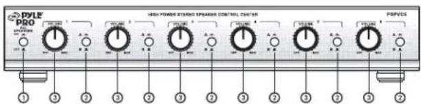
OPERATION
-
Speakers on/off Button Press button in to turn on all speaker pairs. Press again button out to turn off.
-
Amplifier A/B Selector Button Press button to select amplifier A and B.
-
Volume Controls Turn the control knob clockwise to increase the volume and counter-clockwise to decrease or off.
-
Speader Connections The control center divides the power from your receiver/amplifier differently to its speaker terminals. (This is especially noticeable when you connect only one pair of speakers. If you connect more than one pair of speakers, see "Impedance Chart" on page 4 to selector the best terminals to connect.) For the best performance, make the connections based on how frequently you use each set of speakers.
Cautions : To avoid damaging your speakers or receiver/amplifier:
-
Be sure your receiver/amplifier's power is turned off before you make the connections.
●Never let the speaker wire's bare ends touch each other or the adjacent terminals on the control center.
●Do not connect more than one pair of sepakers to each set of terminals. -
Amplifier Connections
Connect the speaker output of your receiver or amplifier (100watts max.). If you are using a second amplifier, connect it to the B amp terminal.
Maximum Amplifier input
100W RMS
150W AVG
Maximum Output per Speaker
18W RMS
50W AVG
100W PEAK
4 or 16 OHMS LOAD.
Insert the speakers' positive (+) wires in the positive terminals, and negative (-) wires into the negative terminals, according to the respective L (left) and R (right) terminals.
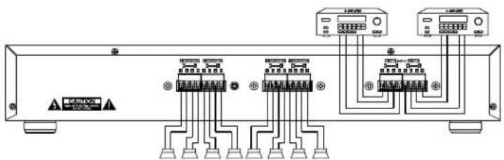

Insert your receiver/amplifier's positive (+) wires into the positive terminals, and negative (-) wires in the negative terminals.
Notes :
- If your receiver/amplifier has more than one set of speaker terminal (A and B), connect only one or the other to the control center.
- For the best results, we recommend 14-gauge, two conductor speaker wire (not supplied) for most connections. If you plan to locate the speakers further than 80 feet from the control center, use a heavier gauge of wire.
IMPEDANCE CHART
Impedance is a measurement of the load placed on your receiver/amplifier by the speakers. The load placed on your receiver/amplifier from the control center will vary depending on how many pairs of speakers you turn on at one time, and on which speakers you turn on. The chart below shows the impedance for all possible combinations of 8-ohm speakers.
PSPVC4
| Speaker Sets On | Impedance (Ω) |
| A,B,C or D | 8 |
| A+B,A+C,A+DB+C,B+D,C+D | 4 |
| A+B+C,A+B+D,A+C+D,B+C+D | 3.1 |
| A+B+C+D | 2.4 |
PSPVC6
| Speaker Sets On | Impedance (Ω) |
| A, B, C, D, E or F | 8 |
| A+B, A+C, A+D,A+E, A+F, B+C,B+D, B+E, B+F,C+D, C+E, C+F, E+F | 4 |
| A+B+C, A+B+D, A+B+EA+B+F, A+C+D, A+C+EA+C+F, A+D+E, A+D+FA+E+F, B+C+D, B+C+EB+C+F, B+D+E, B+D+FC+D+E, C+D+F, D+E+F | 3.1 |
| A+B+C+D, A+B+C+EA+B+C+F, A+C+D+EA+C+D+F, A+D+E+FB+C+D+E, B+C+D+FC+D+E+F | 2.4 |
| A+B+C+D+E+F | 1.7 |
SPECIFICATIONS
| Audio Power Handling | 50W (R.M.S.)/CH, 100W (Max)/CH |
| Frequency Response | 20 Hz to 20KHz |
| Channel Separation | 80 dB |
| Crosstalk between channels | 50 dB |
| Speaker terminal wire size requirements | 14-22 gauge |
| Dimensions (WxHxD) | 430x77x160 mm (PSPVC4/PSPVC6) |
| Weight | 4.0kgs (8.82lbs) (PSPVC4) |
| 5.0kgs (11.02lbs) (PSPVC6) |

Brand : Pyle
Model : PSPVC4
Category : Network switch